EP4191028A1 - Leaf spring and sealing assembly including same - Google Patents
Leaf spring and sealing assembly including same Download PDFInfo
- Publication number
- EP4191028A1 EP4191028A1 EP22210553.8A EP22210553A EP4191028A1 EP 4191028 A1 EP4191028 A1 EP 4191028A1 EP 22210553 A EP22210553 A EP 22210553A EP 4191028 A1 EP4191028 A1 EP 4191028A1
- Authority
- EP
- European Patent Office
- Prior art keywords
- sealing member
- body section
- leaf spring
- locking
- protrusion
- Prior art date
- Legal status (The legal status is an assumption and is not a legal conclusion. Google has not performed a legal analysis and makes no representation as to the accuracy of the status listed.)
- Pending
Links
- 238000007789 sealing Methods 0.000 title claims abstract description 149
- 230000013011 mating Effects 0.000 claims abstract description 49
- 238000003780 insertion Methods 0.000 claims description 19
- 230000037431 insertion Effects 0.000 claims description 19
- 239000007789 gas Substances 0.000 abstract description 36
- 239000000567 combustion gas Substances 0.000 description 7
- 239000000446 fuel Substances 0.000 description 5
- 238000009434 installation Methods 0.000 description 4
- 230000004048 modification Effects 0.000 description 3
- 238000012986 modification Methods 0.000 description 3
- 238000006243 chemical reaction Methods 0.000 description 2
- 238000002485 combustion reaction Methods 0.000 description 2
- 230000006835 compression Effects 0.000 description 2
- 238000007906 compression Methods 0.000 description 2
- 230000007246 mechanism Effects 0.000 description 2
- 239000000203 mixture Substances 0.000 description 2
- 238000006467 substitution reaction Methods 0.000 description 2
- 230000008859 change Effects 0.000 description 1
- 239000012530 fluid Substances 0.000 description 1
- 239000000314 lubricant Substances 0.000 description 1
- 230000009467 reduction Effects 0.000 description 1
Images


Classifications
-
- F—MECHANICAL ENGINEERING; LIGHTING; HEATING; WEAPONS; BLASTING
- F02—COMBUSTION ENGINES; HOT-GAS OR COMBUSTION-PRODUCT ENGINE PLANTS
- F02C—GAS-TURBINE PLANTS; AIR INTAKES FOR JET-PROPULSION PLANTS; CONTROLLING FUEL SUPPLY IN AIR-BREATHING JET-PROPULSION PLANTS
- F02C7/00—Features, components parts, details or accessories, not provided for in, or of interest apart form groups F02C1/00 - F02C6/00; Air intakes for jet-propulsion plants
- F02C7/28—Arrangement of seals
-
- F—MECHANICAL ENGINEERING; LIGHTING; HEATING; WEAPONS; BLASTING
- F01—MACHINES OR ENGINES IN GENERAL; ENGINE PLANTS IN GENERAL; STEAM ENGINES
- F01D—NON-POSITIVE DISPLACEMENT MACHINES OR ENGINES, e.g. STEAM TURBINES
- F01D11/00—Preventing or minimising internal leakage of working-fluid, e.g. between stages
- F01D11/005—Sealing means between non relatively rotating elements
- F01D11/006—Sealing the gap between rotor blades or blades and rotor
-
- F—MECHANICAL ENGINEERING; LIGHTING; HEATING; WEAPONS; BLASTING
- F01—MACHINES OR ENGINES IN GENERAL; ENGINE PLANTS IN GENERAL; STEAM ENGINES
- F01D—NON-POSITIVE DISPLACEMENT MACHINES OR ENGINES, e.g. STEAM TURBINES
- F01D11/00—Preventing or minimising internal leakage of working-fluid, e.g. between stages
- F01D11/001—Preventing or minimising internal leakage of working-fluid, e.g. between stages for sealing space between stator blade and rotor
-
- F—MECHANICAL ENGINEERING; LIGHTING; HEATING; WEAPONS; BLASTING
- F16—ENGINEERING ELEMENTS AND UNITS; GENERAL MEASURES FOR PRODUCING AND MAINTAINING EFFECTIVE FUNCTIONING OF MACHINES OR INSTALLATIONS; THERMAL INSULATION IN GENERAL
- F16J—PISTONS; CYLINDERS; SEALINGS
- F16J15/00—Sealings
- F16J15/16—Sealings between relatively-moving surfaces
- F16J15/34—Sealings between relatively-moving surfaces with slip-ring pressed against a more or less radial face on one member
- F16J15/3436—Pressing means
- F16J15/344—Pressing means the pressing force being applied by means of an elastic ring supporting the slip-ring
-
- F—MECHANICAL ENGINEERING; LIGHTING; HEATING; WEAPONS; BLASTING
- F05—INDEXING SCHEMES RELATING TO ENGINES OR PUMPS IN VARIOUS SUBCLASSES OF CLASSES F01-F04
- F05D—INDEXING SCHEME FOR ASPECTS RELATING TO NON-POSITIVE-DISPLACEMENT MACHINES OR ENGINES, GAS-TURBINES OR JET-PROPULSION PLANTS
- F05D2220/00—Application
- F05D2220/30—Application in turbines
- F05D2220/32—Application in turbines in gas turbines
-
- F—MECHANICAL ENGINEERING; LIGHTING; HEATING; WEAPONS; BLASTING
- F05—INDEXING SCHEMES RELATING TO ENGINES OR PUMPS IN VARIOUS SUBCLASSES OF CLASSES F01-F04
- F05D—INDEXING SCHEME FOR ASPECTS RELATING TO NON-POSITIVE-DISPLACEMENT MACHINES OR ENGINES, GAS-TURBINES OR JET-PROPULSION PLANTS
- F05D2240/00—Components
- F05D2240/55—Seals
- F05D2240/57—Leaf seals
-
- F—MECHANICAL ENGINEERING; LIGHTING; HEATING; WEAPONS; BLASTING
- F05—INDEXING SCHEMES RELATING TO ENGINES OR PUMPS IN VARIOUS SUBCLASSES OF CLASSES F01-F04
- F05D—INDEXING SCHEME FOR ASPECTS RELATING TO NON-POSITIVE-DISPLACEMENT MACHINES OR ENGINES, GAS-TURBINES OR JET-PROPULSION PLANTS
- F05D2260/00—Function
- F05D2260/30—Retaining components in desired mutual position
- F05D2260/36—Retaining components in desired mutual position by a form fit connection, e.g. by interlocking
-
- F—MECHANICAL ENGINEERING; LIGHTING; HEATING; WEAPONS; BLASTING
- F05—INDEXING SCHEMES RELATING TO ENGINES OR PUMPS IN VARIOUS SUBCLASSES OF CLASSES F01-F04
- F05D—INDEXING SCHEME FOR ASPECTS RELATING TO NON-POSITIVE-DISPLACEMENT MACHINES OR ENGINES, GAS-TURBINES OR JET-PROPULSION PLANTS
- F05D2260/00—Function
- F05D2260/30—Retaining components in desired mutual position
- F05D2260/38—Retaining components in desired mutual position by a spring, i.e. spring loaded or biased towards a certain position
-
- F—MECHANICAL ENGINEERING; LIGHTING; HEATING; WEAPONS; BLASTING
- F05—INDEXING SCHEMES RELATING TO ENGINES OR PUMPS IN VARIOUS SUBCLASSES OF CLASSES F01-F04
- F05D—INDEXING SCHEME FOR ASPECTS RELATING TO NON-POSITIVE-DISPLACEMENT MACHINES OR ENGINES, GAS-TURBINES OR JET-PROPULSION PLANTS
- F05D2260/00—Function
- F05D2260/50—Kinematic linkage, i.e. transmission of position
- F05D2260/52—Kinematic linkage, i.e. transmission of position involving springs
Definitions
- the present disclosure relates to a leaf spring inserted between a sealing member, more particularly, a leaf spring inserted between a sealing member installed between various components of a gas turbine, and a sealing assembly including the same.
- turbines such as steam turbines, gas turbines, and the like, are machines that obtain rotating force with impulsive force using a flow of a compressed fluid such as gas.
- the gas turbine generally includes a compressor, a combustor, and a turbine.
- the compressor has a compressor casing in which compressor vanes and compressor blades are alternately arranged, along with an air inlet to provide compressed air.
- the combustor serves to supply fuel to the compressed air provided from the compressor and ignite the air-fuel mixture with a burner to produce high temperature and high pressure combustion gas.
- the turbine has a turbine casing in which turbine vanes and turbine blades are alternately arranged.
- a rotor is centrally disposed through the compressor, the combustor, the turbine, and an exhaust chamber.
- the rotor is rotatably supported by bearings at opposite ends thereof.
- a plurality of disks is fixed to the rotor so that respective blades are attached thereto, and a driving shaft of a driving unit, such as a generator or the like, is coupled to an end side of the rotor on the exhaust chamber side.
- air compressed by the compressor is mixed with fuel and combusted in the combustor to provide hot combustion gas, which is then injected towards the turbine.
- a rotating force is generated and the rotor rotates by the generated rotating force.
- an objective of the present disclosure is to provide a leaf spring inserted between a sealing member installed between various components of a gas turbine to prevent an inflow and outflow of gases a mating sealing member, and a sealing assembly including the same.
- a leaf spring arranged between a sealing member having a locking groove and a mating sealing member having an insertion space into which the sealing member and the leaf spring are inserted, the leaf spring including: a curved body section; a locking protrusion protruding in one direction at an end of the body section to be inserted into the locking groove of the sealing member; and a detachment-prevention protrusion protruding in a direction opposite to the locking protrusion and configured to into contact with one surface of the mating sealing member and prevent the locking protrusion from being detached from the locking groove when the body section is compressed by the sealing member and the mating sealing member.
- the body section may be curved such that a height thereof gradually increases to a predetermined height from both ends to an intermediate portion thereof.
- the locking protrusion may be formed in one or more numbers to protrude downward from the end of the body section.
- the detachment-prevention protrusion may be formed in one or more numbers to protrude upward from the end of the body section.
- two locking protrusions may be formed to protrude downward from the end of the body section, and one detachment-prevention protrusion may be formed to protrude upward between the two locking protrusions.
- a sealing assembly including: a sealing member having a locking groove; a mating sealing member having an insertion space into which the sealing member is inserted; and a leaf spring inserted into the insertion space and disposed between the sealing member and the mating sealing member, the leaf spring including: a curved body section; a locking protrusion protruding in one direction at an end of the body section to be inserted into the locking groove of the sealing member; and a detachment-prevention protrusion protruding in a direction opposite to the locking protrusion and configured to into contact with one surface of the mating sealing member and prevent the locking protrusion from being detached from the locking groove when the body section is compressed by the sealing member and the mating sealing member.
- the body section may be curved such that a height thereof gradually increases to a predetermined height from both ends to an intermediate portion thereof.
- the locking protrusion may be formed in one or more numbers to protrude downward from the end of the body section.
- the detachment-prevention protrusion may be formed to protrude in one or more numbers and protrude upward from the end of the body section.
- two locking protrusions may be formed to protrude downward from the end of the body section, and one detachment-prevention protrusion may be formed to protrude upward between the two locking protrusions.
- a gas turbine including: a sealing assembly mounted between components of the gas turbine to prevent an inflow or outflow of gas, the sealing assembly including: a sealing member mounted in a gap region through which the gas flows inwards or outwards and having a locking groove; a mating sealing member having an insertion space into which the sealing member is inserted; and a leaf spring inserted into the insertion space and disposed between the sealing member and the mating sealing member, the leaf spring including: a curved body section; a locking protrusion protruding in one direction at an end of the body section to be inserted into the locking groove of the sealing member; and a detachment-prevention protrusion protruding in a direction opposite to the locking protrusion and configured to come into contact with one surface of the mating sealing member and prevent the locking protrusion from being detached from the locking groove when the body section is compressed by the sealing member and the mating sealing member.
- the body section may be curved such that a height thereof gradually increases to a predetermined height from both ends to an intermediate portion thereof.
- the locking protrusion may be formed in one or more numbers to protrude downward from the end of the body section.
- the detachment-prevention protrusion may be formed to protrude in one or more numbers and protrude upward from the end of the body section.
- two locking protrusions may be formed to protrude downward from the end of the body section, and one detachment-prevention protrusion may be formed to protrude upward between the two locking protrusions.
- the sealing performance between the various components of a gas turbine is increased to improve the efficiency of a gas turbine as a whole.
- FIG. 1 is a perspective view illustrating the interior of a gas turbine according to an exemplary embodiment the present disclosure
- FIG. 2 is a view conceptually illustrating a section of the gas turbine.
- the gas turbine 1 includes a compressor 10, a combustor 20, and a turbine 30.
- the compressor 10 serves to compress an inflow or outflow of air at a high pressure, and delivers the compressed air to the combustor side.
- the compressor 10 has a plurality of compressor blades installed circumferentially, which rotate by receiving a portion of the power generated from the rotation of the turbine 30, so that the air is fed toward the combustor 20 while being compressed by the rotation of the blade combustor.
- the size and installation angle of the blade in the compressor 10 may vary depending on the installation location.
- the compressed air from the compressor 10 is fed to the combustor 20 so that the compressed air is mixed with fuel provided by fuel-nozzle modules arranged in an annular shape.
- the air-fuel mixture is combusted in a combustion chamber.
- the high-temperature combustion gas generated due to combustion is discharged to the turbine 30 to rotate the same.
- the turbine 30 includes turbine rotor disks 300 that are arranged in a multi-stage around a center tie rod 400 that axially couples the turbine rotor disks 300.
- the turbine rotor disks 300 include a plurality of turbine blades 100 arranged circumferentially.
- the turbine blade 100 may be coupled to the turbine rotor disk 300 in a dovetail-fit or the like.
- a turbine vane 200 is provided between the turbine blades 100 while being fixed to a housing to guide the flow direction of the combustion gas passing through the turbine blades 100.
- the turbine 30 may include n turbine vanes 200 and n turbine blades 100 alternately arranged along the axial direction of the gas turbine 1.
- turbine vanes 200 and turbine blades 100 are arranged in n multiple stages.
- the hot combustion gas passes through the turbine vanes 200 and the turbine blades 100 along the axial direction to rotate the turbine blades 100.
- sealing members for preventing the inflow and outflow of compressed air and/or combustion gas are installed between various components of a gas turbine.
- the sealing members are installed by being inserted into a mating sealing member.
- the sealing between a turbine blade 100 and a turbine vane 200 will be described as an example, but the present disclosure is not limited thereto.
- the sealing described below may be applied to a compressor blade and a compressor vane or to any other portion in the gas turbine where a sealing is required.
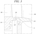
- FIG. 3 is an enlarged cross-sectional view illustrating a portion, i.e., a part of section A of FIG. 2 , of a turbine to which a leaf spring may be applied according to an embodiment of the present disclosure.
- a blade root member 110 is formed at a lower portion of a turbine blade 100, and a sealing wing 120 extending in an axial direction is formed on a lateral side surface of the blade root member 110.
- a turbine vane inner shroud 210 is formed at a lower portion of a turbine vane 200, and a sealing plate 220 extending in the axial direction is formed on a lateral side surface of the turbine vane inner shroud 210.
- the sealing plate 220 is spaced apart from the sealing wing 120 by a predetermined distance to form a gap G. Since gas flows inward or outward through the gap G, a sealing member may be installed in the gap G according to an embodiment, to prevent such inward/outward gas flow.
- FIG. 4 is a view illustrating a state in which the leaf spring is inserted between a sealing member and a mating sealing member according to an embodiment of the present disclosure.
- the sealing plate 220 may be provided with an insertion space 221 into which the sealing member 230 is inserted according to an embodiment.
- the insertion space 221 may be formed at the lower surface of the sealing plate 220 from the lower surface toward a radially outward direction.
- the sealing member 230 may have a predetermined shape to block an inflow or outflow of gas through the gap G.
- the insertion space 221 and the sealing member 230 are formed to extend in a circumferential direction to have an annular ring shape in general. In this case, the sealing plate 220 becomes a mating sealing member with which the sealing member 230 is assembled. In other words, the sealing member 230 may be inserted into the sealing plate 220.
- a part of the sealing member 230 may be disposed to protrude out of the insertion space 221 and to block an inflow/outflow of gas in the gap G while another part of the sealing member 230 is disposed inside the insertion space 221. It is understood that, among various components of a gas turbine, any other components into which the sealing member is inserted may be considered the mating sealing members, according to an embodiment.
- a leaf spring 1000 may be disposed between the sealing member and the mating sealing member for convenience of assembly.
- the leaf spring, to successively function, is preferred to satisfy the following conditions.
- FIG. 5 is an enlarged view of section B of FIG. 4
- FIG. 6 is a perspective view illustrating a leaf spring according to an embodiment of the present disclosure.
- the leaf spring 1000 according to an embodiment of the present disclosure includes a body section 1100, a locking protrusion 1200, and a detachment-prevention protrusion 1300.
- the leaf spring 1000 is disposed in the insertion space 221 between the sealing member 230 and the mating sealing member (e.g., the sealing plate 220).
- the mating sealing member e.g., the sealing plate 220
- reference numeral 220 will also refer to a mating sealing member.
- the body section 1100 is formed in a curved bar shape in general.
- the body section 1100 is curvedly formed such that a height thereof gradually increases to a predetermined height from both ends to a center portion thereof.
- a virtual plane passing the both ends of the of the body section 110 is the ground for measuring the predetermined height and the direction from the virtual plane toward the center portion having the predetermined height may be referred to as a height direction.
- the "predetermined height" may be set differently for each component of a gas turbine where a sealing is required, for example, in this case, for the sealing member 230 and the mating sealing member 220 (i.e., the sealing plate 220, for an embodiment described herein).
- the body section 1100 may be configured to apply an elastic force pushing the sealing member 230 away from the mating sealing member 220.
- the body section 1100 may be in a form with a curved shape at a portion toward an end to smoothly meet the sealing member and another curved shape at a portion toward the center portion to smoothly meet the mating sealing member.
- the body section 1100 may be provided with a locking protrusion 1200 protruding in a first direction at one end of the body section 1100.
- the locking protrusion 1200 may be formed to protrude downward from the end of the body section 1100 according to an embodiment. The downward direction may be the opposite direction to the height direction.
- One or more locking protrusions 1200 may be formed at the end of the body section 1100. As an example, two locking protrusions 1200 are illustrated in the drawings. According to an embodiment the locking protrusion 1200 is fitted and inserted into a locking groove 231 formed in the sealing member 230.
- a detachment-prevention protrusion 1300 may be formed to protrude in a second direction at the end of the body section 1100.
- the detachment-prevention protrusion 1300 may be formed to protrude upward from the end of the body section 1100 according to an embodiment.
- the upward direction may be the same direction to the height direction.
- One or more detachment-prevention protrusions 1300 may be formed at the end of the body section 1100.
- it is illustrated that one detachment-prevention protrusion 1300 is formed to protrude upward between two locking protrusions 1200 formed to protrude downward.
- FIG. 7 is a perspective view illustrating a leaf spring R without the detachment-prevention protrusion 1300
- FIG. 8 is a view to illustrate a potential disadvantage with the leaf spring R of FIG. 7 .
- a leaf spring R includes a body section 1100 and a locking protrusion 1200, without the detachment-prevention protrusion 1300.
- the leaf spring R may remain locked to and is not detached from the sealing member 230.
- the locking protrusion 1200 may moves upwards as a reaction to the compression force.
- the upward movement of the locking protrusion 1200 may be caused due to the curved shape at a portion toward the end in the body section.
- the locking protrusion 1200 may escape from the locking groove 231, so the leaf spring R may slide on an upper surface of the sealing member 230.
- the locking protrusion 1200 may be detached from the locking groove 231 due to vibration generated during operation of a gas turbine. That is, with the leaf spring according to FIG. 7 , the First Condition among the above described conditions for the successful leaf spring may be satisfied, but the Second Condition may not be satisfied. This can cause failure between various components of a gas turbine may occur, thereby reducing the overall operation efficiency of a gas turbine.
- FIG. 9 is a view illustrating an installation state of a leaf spring with detachment-prevention protrusion 1300 according to an embodiment of the present disclosure.
- the leaf spring 1000 maintains a fixed and locked state when assembled with the sealing member 230.
- the assembly of the sealing member 230 and the leaf spring 1000 is disposed in the insertion space between the sealing member 230 and the mating sealing member 220 and is pressed or compressed by the mating sealing member 220, even though the locking protrusion 1200 is subjected to an upward movement force due to a reaction to the compression force, the detachment-prevention protrusion 1300 comes into contact with an inner wall of the insertion space of the mating sealing member 220 so that the movement of the locking protrusion 1200 is restricted.
- the detachment-prevention protrusion 1300 may be in a length such that the gap between the tip of the detachment-prevention 1300 and the mating sealing member 220 is shorter than the length of the locking protraction 1200 inserted into the locking groove 231.
- the locking protrusion 1200 it is possible to prevent the locking protrusion 1200 from being detached during the normal state. This can improve the sealing performance between the various components of a gas turbine, thereby improving the operation efficiency of the gas turbine as a whole.
- the leaf spring 1000 has been described as a single unit. However, according to an embodiment, when designing a gas turbine, the sealing member 230 and the mating sealing member 220, and the leaf spring 1000 may be designed together.
- the sealing member 230 having a suitable shape and a leaf spring 100 having a suitable shape and size to be disposed between the sealing member 230 and the mating sealing member 220 may be designed accordingly. Therefore, the sealing member 230 and the mating sealing member 230, and the leaf spring 1000 may constitute a sealing assembly.
Landscapes
- Engineering & Computer Science (AREA)
- General Engineering & Computer Science (AREA)
- Mechanical Engineering (AREA)
- Chemical & Material Sciences (AREA)
- Combustion & Propulsion (AREA)
- Gasket Seals (AREA)
- Turbine Rotor Nozzle Sealing (AREA)
Abstract
A leaf spring inserted between a sealing member installed between various components of a gas turbine to prevent an inflow and outflow of gases and a mating sealing member, and a sealing assembly including the same are proposed. The leaf spring includes a curved body section, a locking protrusion protruding in one direction at an end of the body section so as to be fitted into the locking groove of the sealing member, and a detachment-prevention protrusion protruding in a direction opposite to the locking protrusion and configured to comes into contact with one surface of the mating sealing member and prevent the locking protrusion from being detached from the locking groove when the body section is compressed by the sealing member and the mating sealing member.
Description
- The present disclosure relates to a leaf spring inserted between a sealing member, more particularly, a leaf spring inserted between a sealing member installed between various components of a gas turbine, and a sealing assembly including the same.
- Generally, turbines, such as steam turbines, gas turbines, and the like, are machines that obtain rotating force with impulsive force using a flow of a compressed fluid such as gas.
- The gas turbine generally includes a compressor, a combustor, and a turbine. The compressor has a compressor casing in which compressor vanes and compressor blades are alternately arranged, along with an air inlet to provide compressed air.
- The combustor serves to supply fuel to the compressed air provided from the compressor and ignite the air-fuel mixture with a burner to produce high temperature and high pressure combustion gas.
- The turbine has a turbine casing in which turbine vanes and turbine blades are alternately arranged. A rotor is centrally disposed through the compressor, the combustor, the turbine, and an exhaust chamber.
- The rotor is rotatably supported by bearings at opposite ends thereof. A plurality of disks is fixed to the rotor so that respective blades are attached thereto, and a driving shaft of a driving unit, such as a generator or the like, is coupled to an end side of the rotor on the exhaust chamber side.
- Since such a gas turbine is devoid of a reciprocating mechanism such as a piston of a 4-stroke engine, there are no friction-causing features such as piston-cylinder contact parts, and thus the turbine has advantages of a significant reduction in lubricant consumption and amplitude of vibration, which are typical characteristics of a reciprocating mechanism, whereby high speed movement is enabled.
- Briefly explaining the operation of the gas turbine, air compressed by the compressor is mixed with fuel and combusted in the combustor to provide hot combustion gas, which is then injected towards the turbine. As the injected combustion gas passes through the turbine vanes and the turbine blades, a rotating force is generated and the rotor rotates by the generated rotating force.
- The foregoing is intended merely to aid in the understanding of the background of the present disclosure, and is not intended to mean that the present disclosure falls within the purview of the related art that is already known to those skilled in the art.
- Accordingly, the present disclosure has been made keeping in mind the above problems occurring in the related art, and an objective of the present disclosure is to provide a leaf spring inserted between a sealing member installed between various components of a gas turbine to prevent an inflow and outflow of gases a mating sealing member, and a sealing assembly including the same.
- In an aspect of the present disclosure, there is provided a leaf spring arranged between a sealing member having a locking groove and a mating sealing member having an insertion space into which the sealing member and the leaf spring are inserted, the leaf spring including: a curved body section; a locking protrusion protruding in one direction at an end of the body section to be inserted into the locking groove of the sealing member; and a detachment-prevention protrusion protruding in a direction opposite to the locking protrusion and configured to into contact with one surface of the mating sealing member and prevent the locking protrusion from being detached from the locking groove when the body section is compressed by the sealing member and the mating sealing member.
- In an embodiment, the body section may be curved such that a height thereof gradually increases to a predetermined height from both ends to an intermediate portion thereof.
- In an embodiment, the locking protrusion may be formed in one or more numbers to protrude downward from the end of the body section.
- In an embodiment, the detachment-prevention protrusion may be formed in one or more numbers to protrude upward from the end of the body section.
- In an embodiment, two locking protrusions may be formed to protrude downward from the end of the body section, and one detachment-prevention protrusion may be formed to protrude upward between the two locking protrusions.
- In another aspect of the present disclosure, there is provided a sealing assembly including: a sealing member having a locking groove; a mating sealing member having an insertion space into which the sealing member is inserted; and a leaf spring inserted into the insertion space and disposed between the sealing member and the mating sealing member, the leaf spring including: a curved body section; a locking protrusion protruding in one direction at an end of the body section to be inserted into the locking groove of the sealing member; and a detachment-prevention protrusion protruding in a direction opposite to the locking protrusion and configured to into contact with one surface of the mating sealing member and prevent the locking protrusion from being detached from the locking groove when the body section is compressed by the sealing member and the mating sealing member.
- In an embodiment, the body section may be curved such that a height thereof gradually increases to a predetermined height from both ends to an intermediate portion thereof.
- In an embodiment, the locking protrusion may be formed in one or more numbers to protrude downward from the end of the body section.
- In an embodiment, the detachment-prevention protrusion may be formed to protrude in one or more numbers and protrude upward from the end of the body section.
- In an embodiment, two locking protrusions may be formed to protrude downward from the end of the body section, and one detachment-prevention protrusion may be formed to protrude upward between the two locking protrusions.
- In a further aspect of the present disclosure, there is provided a gas turbine including: a sealing assembly mounted between components of the gas turbine to prevent an inflow or outflow of gas, the sealing assembly including: a sealing member mounted in a gap region through which the gas flows inwards or outwards and having a locking groove; a mating sealing member having an insertion space into which the sealing member is inserted; and a leaf spring inserted into the insertion space and disposed between the sealing member and the mating sealing member, the leaf spring including: a curved body section; a locking protrusion protruding in one direction at an end of the body section to be inserted into the locking groove of the sealing member; and a detachment-prevention protrusion protruding in a direction opposite to the locking protrusion and configured to come into contact with one surface of the mating sealing member and prevent the locking protrusion from being detached from the locking groove when the body section is compressed by the sealing member and the mating sealing member.
- In an embodiment, the body section may be curved such that a height thereof gradually increases to a predetermined height from both ends to an intermediate portion thereof.
- In an embodiment, the locking protrusion may be formed in one or more numbers to protrude downward from the end of the body section.
- In an embodiment, the detachment-prevention protrusion may be formed to protrude in one or more numbers and protrude upward from the end of the body section.
- In an embodiment, two locking protrusions may be formed to protrude downward from the end of the body section, and one detachment-prevention protrusion may be formed to protrude upward between the two locking protrusions.
- Other details of implementations according to various aspects of the present disclosure are included in the detailed description below.
- According to embodiments of the present disclosure, the sealing performance between the various components of a gas turbine is increased to improve the efficiency of a gas turbine as a whole.
-
-
FIG. 1 is a view illustrating the interior of a gas turbine according to an embodiment of the present disclosure; -
FIG. 2 is a view conceptually illustrating a section of the gas turbine according to the embodiment of the present disclosure; -
FIG. 3 is an enlarged cross-sectional view illustrating a portion of a turbine to which a leaf spring is applied; -
FIG. 4 is a view illustrating a state in which the leaf spring is inserted between a sealing member and a mating sealing member according to an embodiment of the present disclosure; -
FIG. 5 is an enlarged view of section B ofFIG. 4 ; -
FIG. 6 is a perspective view illustrating a leaf spring according to an embodiment of the present disclosure; -
FIG. 7 is a perspective view illustrating a leaf spring without a detachment-prevention protrusion; -
FIG. 8 is a view illustrating a potential disadvantage with the leaf spring ofFIG. 7 ; and -
FIG. 9 is a view illustrating an installation state of a leaf spring according to an embodiment of the present disclosure. - Hereinafter, exemplary embodiments of the present disclosure will be described in detail with reference to the accompanying drawings. However, it should be noted that the present disclosure is not limited thereto, but may include all of modifications, equivalents or substitutions within the spirit and scope of the present disclosure.
- Terms used herein are used to merely describe specific embodiments, and are not intended to limit the present disclosure. As used herein, an element expressed as a singular form includes a plurality of elements, unless the context clearly indicates otherwise. Further, it will be understood that the terms "comprising" or "including" specifies the presence of stated features, numbers, steps, operations, elements, parts, or combinations thereof, but does not preclude the presence or addition of one or more other features, numbers, steps, operations, elements, parts, or combinations thereof. Hereinafter, preferred embodiments of the present disclosure will be described in detail with reference to the accompanying drawings.
- Hereinafter, preferred embodiments of the present disclosure will be described in detail with reference to the accompanying drawings. It is noted that like elements are denoted in the drawings by like reference symbols as whenever possible. Further, the detailed description of known functions and configurations that may obscure the gist of the present disclosure will be omitted. For the same reason, some of the elements in the drawings are exaggerated, omitted, or schematically illustrated.
-
FIG. 1 is a perspective view illustrating the interior of a gas turbine according to an exemplary embodiment the present disclosure, andFIG. 2 is a view conceptually illustrating a section of the gas turbine. - As illustrated in
FIGS. 1 and 2 , thegas turbine 1 includes acompressor 10, acombustor 20, and aturbine 30. Thecompressor 10 serves to compress an inflow or outflow of air at a high pressure, and delivers the compressed air to the combustor side. Thecompressor 10 has a plurality of compressor blades installed circumferentially, which rotate by receiving a portion of the power generated from the rotation of theturbine 30, so that the air is fed toward thecombustor 20 while being compressed by the rotation of the blade combustor. The size and installation angle of the blade in thecompressor 10 may vary depending on the installation location. - The compressed air from the
compressor 10 is fed to thecombustor 20 so that the compressed air is mixed with fuel provided by fuel-nozzle modules arranged in an annular shape. The air-fuel mixture is combusted in a combustion chamber. The high-temperature combustion gas generated due to combustion is discharged to theturbine 30 to rotate the same. - The
turbine 30 includesturbine rotor disks 300 that are arranged in a multi-stage around acenter tie rod 400 that axially couples theturbine rotor disks 300. Theturbine rotor disks 300 include a plurality ofturbine blades 100 arranged circumferentially. Theturbine blade 100 may be coupled to theturbine rotor disk 300 in a dovetail-fit or the like. In addition, aturbine vane 200 is provided between theturbine blades 100 while being fixed to a housing to guide the flow direction of the combustion gas passing through theturbine blades 100. - As illustrated in
FIG. 2 , theturbine 30 may includen turbine vanes 200 andn turbine blades 100 alternately arranged along the axial direction of thegas turbine 1. In other words,turbine vanes 200 andturbine blades 100 are arranged in n multiple stages. The hot combustion gas passes through theturbine vanes 200 and theturbine blades 100 along the axial direction to rotate theturbine blades 100. - Various sealing members for preventing the inflow and outflow of compressed air and/or combustion gas are installed between various components of a gas turbine. The sealing members are installed by being inserted into a mating sealing member. In the following description, the sealing between a
turbine blade 100 and aturbine vane 200 will be described as an example, but the present disclosure is not limited thereto. For example, the sealing described below may be applied to a compressor blade and a compressor vane or to any other portion in the gas turbine where a sealing is required. -
FIG. 3 is an enlarged cross-sectional view illustrating a portion, i.e., a part of section A ofFIG. 2 , of a turbine to which a leaf spring may be applied according to an embodiment of the present disclosure. - Referring to
FIG. 3 , ablade root member 110 is formed at a lower portion of aturbine blade 100, and a sealingwing 120 extending in an axial direction is formed on a lateral side surface of theblade root member 110. In addition, a turbine vaneinner shroud 210 is formed at a lower portion of aturbine vane 200, and asealing plate 220 extending in the axial direction is formed on a lateral side surface of the turbine vaneinner shroud 210. The sealingplate 220 is spaced apart from the sealingwing 120 by a predetermined distance to form a gap G. Since gas flows inward or outward through the gap G, a sealing member may be installed in the gap G according to an embodiment, to prevent such inward/outward gas flow. -
FIG. 4 is a view illustrating a state in which the leaf spring is inserted between a sealing member and a mating sealing member according to an embodiment of the present disclosure. - Referring to
FIG. 4 , the sealingplate 220 may be provided with aninsertion space 221 into which the sealingmember 230 is inserted according to an embodiment. Theinsertion space 221 may be formed at the lower surface of the sealingplate 220 from the lower surface toward a radially outward direction. The sealingmember 230 may have a predetermined shape to block an inflow or outflow of gas through the gap G. Theinsertion space 221 and the sealingmember 230 are formed to extend in a circumferential direction to have an annular ring shape in general. In this case, the sealingplate 220 becomes a mating sealing member with which the sealingmember 230 is assembled. In other words, the sealingmember 230 may be inserted into the sealingplate 220. According to an embodiment, a part of the sealingmember 230 may be disposed to protrude out of theinsertion space 221 and to block an inflow/outflow of gas in the gap G while another part of the sealingmember 230 is disposed inside theinsertion space 221. It is understood that, among various components of a gas turbine, any other components into which the sealing member is inserted may be considered the mating sealing members, according to an embodiment. - Meanwhile, according to an embodiment, a
leaf spring 1000 may be disposed between the sealing member and the mating sealing member for convenience of assembly. The leaf spring, to successively function, is preferred to satisfy the following conditions. - ① Upon being assembled with the sealing member, the leaf spring should not be separated from the sealing member. (the "First Condition")
- ② Even after the assembly of the sealing member and the leaf spring is placed on the mating sealing member and a pressing or compressing force is applied from the mating sealing member toward the leaf spring, the leaf spring should not be separated from the sealing member. (the "Second Condition")
- This will be described with reference to
FIGS. 5 and 6. FIG. 5 is an enlarged view of section B ofFIG. 4 , andFIG. 6 is a perspective view illustrating a leaf spring according to an embodiment of the present disclosure. - Referring to
FIGS. 5 and 6 , theleaf spring 1000 according to an embodiment of the present disclosure includes abody section 1100, alocking protrusion 1200, and a detachment-prevention protrusion 1300. Theleaf spring 1000 is disposed in theinsertion space 221 between the sealingmember 230 and the mating sealing member (e.g., the sealing plate 220). Hereinafter,reference numeral 220 will also refer to a mating sealing member. - The
body section 1100 is formed in a curved bar shape in general. Thebody section 1100 is curvedly formed such that a height thereof gradually increases to a predetermined height from both ends to a center portion thereof. A virtual plane passing the both ends of the of thebody section 110 is the ground for measuring the predetermined height and the direction from the virtual plane toward the center portion having the predetermined height may be referred to as a height direction. Here, the "predetermined height" may be set differently for each component of a gas turbine where a sealing is required, for example, in this case, for the sealingmember 230 and the mating sealing member 220 (i.e., the sealingplate 220, for an embodiment described herein). Thebody section 1100 may be configured to apply an elastic force pushing the sealingmember 230 away from themating sealing member 220. Thebody section 1100 may be in a form with a curved shape at a portion toward an end to smoothly meet the sealing member and another curved shape at a portion toward the center portion to smoothly meet the mating sealing member. - According to an embodiment, the
body section 1100 may be provided with alocking protrusion 1200 protruding in a first direction at one end of thebody section 1100. For example, the lockingprotrusion 1200 may be formed to protrude downward from the end of thebody section 1100 according to an embodiment. The downward direction may be the opposite direction to the height direction. One ormore locking protrusions 1200 may be formed at the end of thebody section 1100. As an example, two lockingprotrusions 1200 are illustrated in the drawings. According to an embodiment thelocking protrusion 1200 is fitted and inserted into a lockinggroove 231 formed in the sealingmember 230. - According to an embodiment, a detachment-
prevention protrusion 1300 may be formed to protrude in a second direction at the end of thebody section 1100. For example, the detachment-prevention protrusion 1300 may be formed to protrude upward from the end of thebody section 1100 according to an embodiment. The upward direction may be the same direction to the height direction. One or more detachment-prevention protrusions 1300 may be formed at the end of thebody section 1100. As an example, in the drawings, it is illustrated that one detachment-prevention protrusion 1300 is formed to protrude upward between two lockingprotrusions 1200 formed to protrude downward. -
FIG. 7 is a perspective view illustrating a leaf spring R without the detachment-prevention protrusion 1300, andFIG. 8 is a view to illustrate a potential disadvantage with the leaf spring R ofFIG. 7 . - Referring to
FIG. 7 , a leaf spring R includes abody section 1100 and alocking protrusion 1200, without the detachment-prevention protrusion 1300. - Referring to
FIG. 8 , upon assembly with the sealingmember 230, the leaf spring R may remain locked to and is not detached from the sealingmember 230. - However, when the assembly of the sealing
member 230 and the leaf spring R is disposed in the insertion space between the sealingmember 230 and themating sealing member 220 and the pressing or compressing force is applied from themating sealing member 220 to the leaf spring R, the lockingprotrusion 1200 may moves upwards as a reaction to the compression force. The upward movement of thelocking protrusion 1200 may be caused due to the curved shape at a portion toward the end in the body section. When thelocking protrusion 1200 moves upward, the lockingprotrusion 1200 may escape from the lockinggroove 231, so the leaf spring R may slide on an upper surface of the sealingmember 230. Alternatively, even if thelocking protrusion 1200 is not detached during a normal state, the locking protrusion may be detached from the lockinggroove 231 due to vibration generated during operation of a gas turbine. That is, with the leaf spring according toFIG. 7 , the First Condition among the above described conditions for the successful leaf spring may be satisfied, but the Second Condition may not be satisfied. This can cause failure between various components of a gas turbine may occur, thereby reducing the overall operation efficiency of a gas turbine. -
FIG. 9 is a view illustrating an installation state of a leaf spring with detachment-prevention protrusion 1300 according to an embodiment of the present disclosure. - Referring to
FIG. 9 , theleaf spring 1000 maintains a fixed and locked state when assembled with the sealingmember 230. In addition, when the assembly of the sealingmember 230 and theleaf spring 1000 is disposed in the insertion space between the sealingmember 230 and themating sealing member 220 and is pressed or compressed by themating sealing member 220, even though thelocking protrusion 1200 is subjected to an upward movement force due to a reaction to the compression force, the detachment-prevention protrusion 1300 comes into contact with an inner wall of the insertion space of themating sealing member 220 so that the movement of thelocking protrusion 1200 is restricted. According to embodiment, the detachment-prevention protrusion 1300 may be in a length such that the gap between the tip of the detachment-prevention 1300 and themating sealing member 220 is shorter than the length of the lockingprotraction 1200 inserted into the lockinggroove 231. As a result, it is possible to prevent thelocking protrusion 1200 from being detached during the normal state. This can improve the sealing performance between the various components of a gas turbine, thereby improving the operation efficiency of the gas turbine as a whole. - Meanwhile, in the above description, the
leaf spring 1000 has been described as a single unit. However, according to an embodiment, when designing a gas turbine, the sealingmember 230 and themating sealing member 220, and theleaf spring 1000 may be designed together. - That is, when the
mating sealing member 220 is determined, the sealingmember 230 having a suitable shape and aleaf spring 100 having a suitable shape and size to be disposed between the sealingmember 230 and themating sealing member 220 may be designed accordingly. Therefore, the sealingmember 230 and themating sealing member 230, and theleaf spring 1000 may constitute a sealing assembly. - While the embodiments of the present disclosure have been described, it will be apparent to those skilled in the art that various modifications and variations can be made in the present disclosure through addition, change, omission, or substitution of components without departing from the spirit of the invention as set forth in the appended claims, and such modifications and changes may also be included within the scope of the present disclosure. Also, it is noted that any one feature of an embodiment of the present disclosure described in the specification may be applied to another embodiment of the present disclosure.
Claims (15)
- A leaf spring, wherein the leaf spring is arranged between a sealing member (230) having a locking groove (231) and a mating sealing member having an insertion space (221) into which the sealing member (230) and the leaf spring are inserted, the leaf spring comprising:a curved body section (1100);a locking protrusion (1200) protruding in one direction at an end of the body section (1100) to be inserted into the locking groove (231) of the sealing member (230); anda detachment-prevention protrusion (1300) protruding in a direction opposite to the locking protrusion (1200) and configured to come into contact with one surface of the mating sealing member and prevent the locking protrusion (1200) from being detached from the locking groove (231) when the body section (1100) is compressed by the sealing member (230) and the mating sealing member.
- The leaf spring of claim 1, wherein the body section (1100) is curved such that a height thereof gradually increases to a predetermined height from both ends to an intermediate portion thereof.
- The leaf spring of claims 1 or 2, wherein the locking protrusion (1200) is formed in one or more numbers to protrude downward from the end of the body section (1100).
- The leaf spring according to any one of claims 1 to 3, wherein the detachment-prevention protrusion (1300) is formed in one or more numbers to protrude upward from the end of the body section (1100).
- The leaf spring according to any one of claims 1 to 4, wherein two locking protrusions (1200) are formed to protrude downward from the end of the body section (1100), and one detachment-prevention protrusion (1300) is formed to protrude upward between the two locking protrusions (1200).
- A sealing assembly comprising:a sealing member (230) having a locking groove (231);a mating sealing member having an insertion space (221) into which the sealing member (230) is inserted; anda leaf spring inserted into the insertion space (221) and disposed between the sealing member (230) and the mating sealing member, the leaf spring comprising:a curved body section (1100);a locking protrusion (1200) protruding in one direction at an end of the body section (1100) to be inserted into the locking groove (231) of the sealing member (230); anda detachment-prevention protrusion (1300) protruding in a direction opposite to the locking protrusion (1200) and configured to come into contact with one surface of the mating sealing member and prevent the locking protrusion (1200) from being detached from the locking groove (231) when the body section (1100) is compressed by the sealing member (230) and the mating sealing member.
- The sealing assembly of claim 6, wherein the body section (1100) is curved such that a height thereof gradually increases to a predetermined height from both ends to an intermediate portion thereof.
- The sealing assembly of claims 6 or 7, wherein the locking protrusion (1200) is formed in one or more numbers to protrude downward from the end of the body section (1100).
- The sealing assembly according to any one of claims 6 to 8, wherein the detachment-prevention protrusion (1300) is formed in one or more numbers to protrude upward from the end of the body section (1100).
- The sealing assembly according to any one of claims 6 to 9, wherein two locking protrusions (1200) are formed to protrude downward from the end of the body section (1100), and one detachment-prevention protrusion (1300) is formed to protrude upward between the two locking protrusions (1200).
- A gas turbine comprising:
a sealing assembly mounted between components of the gas turbine to prevent an inflow or outflow of gas, the sealing assembly comprising:a sealing member (230) having a locking groove (231);a mating sealing member having an insertion space (221) into which the sealing member (230) is inserted; anda leaf spring inserted into the insertion space (221) and disposed between the sealing member (230) and the mating sealing member, the leaf spring comprising:a curved body section (1100);a locking protrusion (1200) protruding in one direction at an end of the body section (1100) to be inserted into the locking groove (231) of the sealing member (230); anda detachment-prevention protrusion (1300) protruding in a direction opposite to the locking protrusion (1200) and configured to come into contact with one surface of the mating sealing member and prevent the locking protrusion (1200) from being detached from the locking groove (231) when the body section (1100) is compressed by the sealing member (230) and the mating sealing member. - The gas turbine of claim 11, wherein the body section (1100) is curved such that a height thereof gradually increases to a predetermined height from both ends to an intermediate portion thereof.
- The gas turbine of claims 11 or 12, wherein the locking protrusion (1200) is formed in one or more numbers to protrude downward from the end of the body section (1100).
- The gas turbine according to any one of claims 11 to 13, wherein the detachment-prevention protrusion is formed in one or more numbers to protrude upward from the end of the body section.
- The gas turbine according to any one of claims 11 to 14, wherein two locking protrusions (1200) are formed to protrude downward from the end of the body section (1100), and one detachment-prevention protrusion (1300) is formed to protrude upward between the two locking protrusions (1200).
Applications Claiming Priority (1)
| Application Number | Priority Date | Filing Date | Title |
|---|---|---|---|
| KR1020210170002A KR20230082253A (en) | 2021-12-01 | 2021-12-01 | Leaf spring and sealing assembly comprising it |
Publications (1)
| Publication Number | Publication Date |
|---|---|
| EP4191028A1 true EP4191028A1 (en) | 2023-06-07 |
Family
ID=84367379
Family Applications (1)
| Application Number | Title | Priority Date | Filing Date |
|---|---|---|---|
| EP22210553.8A Pending EP4191028A1 (en) | 2021-12-01 | 2022-11-30 | Leaf spring and sealing assembly including same |
Country Status (3)
| Country | Link |
|---|---|
| US (1) | US11913384B1 (en) |
| EP (1) | EP4191028A1 (en) |
| KR (1) | KR20230082253A (en) |
Citations (3)
| Publication number | Priority date | Publication date | Assignee | Title |
|---|---|---|---|---|
| KR100569648B1 (en) * | 1999-02-11 | 2006-04-11 | 제너럴 일렉트릭 캄파니 | Variable clearance packing ring with clips for preventing circumferential displacement |
| US20080019836A1 (en) * | 2004-02-11 | 2008-01-24 | Mtu Aero Engines Gmbh | Damping Arrangement for Guide Vanes |
| US20090010762A1 (en) * | 2007-04-27 | 2009-01-08 | Snecma | Damper for turbomachine vanes |
Family Cites Families (20)
| Publication number | Priority date | Publication date | Assignee | Title |
|---|---|---|---|---|
| US2786648A (en) * | 1950-04-04 | 1957-03-26 | United Aircraft Corp | Blade locking device |
| GB691380A (en) | 1950-07-01 | 1953-05-13 | Power Jets Res & Dev Ltd | Improvements relating to bladed rotors for compressors, turbines or like apparatus |
| US5374068A (en) * | 1991-05-07 | 1994-12-20 | General Electric Co. | Method for providing uniform radial clearance of labyrinth seals between rotating and stationary components |
| US5181308A (en) | 1991-07-22 | 1993-01-26 | Westinghouse Electric Corp. | Method for installing annular seals |
| US6022027A (en) * | 1997-12-18 | 2000-02-08 | General Electric Co. | Variable clearance packing ring with clips for preventing circumferential displacement |
| US6331006B1 (en) * | 2000-01-25 | 2001-12-18 | General Electric Company | Brush seal mounting in supporting groove using flat spring with bifurcated end |
| US6786488B2 (en) | 2002-07-18 | 2004-09-07 | Mitsubishi Heavy Industries, Ltd. | Seal structure, turbine having the same, and leak-preventing seal system for rotating shaft |
| US6935634B2 (en) * | 2003-05-08 | 2005-08-30 | General Electric Company | Steam turbine packing spring |
| JP2009108918A (en) | 2007-10-30 | 2009-05-21 | Toshiba Corp | Seal device for rotary machine, and rotary machine |
| JP5123802B2 (en) | 2008-09-16 | 2013-01-23 | 矢崎総業株式会社 | connector |
| EP2562356A1 (en) | 2011-08-24 | 2013-02-27 | Siemens Aktiengesellschaft | Blade assembly |
| KR102031255B1 (en) | 2012-02-20 | 2019-10-11 | 보르그워너 인코퍼레이티드 | Bearing housing of an exhaust-gas turbocharger |
| KR101327861B1 (en) | 2013-06-28 | 2013-11-11 | 조정봉 | Oil deflector |
| JP2016156421A (en) | 2015-02-24 | 2016-09-01 | 株式会社東芝 | Labyrinth seal device and turbo machinery |
| US9822668B2 (en) * | 2015-04-27 | 2017-11-21 | United Technologies Corporation | Blade outer air seal spring clips |
| KR101572907B1 (en) * | 2015-05-27 | 2015-12-11 | 조정봉 | Flexible packing ring for turbine |
| KR101920693B1 (en) | 2016-12-21 | 2019-02-13 | 두산중공업 주식회사 | Turbine including a sealing member for preventing gas ingestion. |
| KR200487211Y1 (en) | 2017-07-31 | 2018-08-22 | 한전케이피에스 주식회사 | Gas turbine enclosure panel joint seal |
| KR102038112B1 (en) | 2017-10-13 | 2019-10-29 | 두산중공업 주식회사 | Combustor and gas turbine including the same |
| KR20210106658A (en) | 2020-02-21 | 2021-08-31 | 두산중공업 주식회사 | Sealing assembly and gas turbine comprising the same |
-
2021
- 2021-12-01 KR KR1020210170002A patent/KR20230082253A/en not_active Application Discontinuation
-
2022
- 2022-11-28 US US18/058,900 patent/US11913384B1/en active Active
- 2022-11-30 EP EP22210553.8A patent/EP4191028A1/en active Pending
Patent Citations (3)
| Publication number | Priority date | Publication date | Assignee | Title |
|---|---|---|---|---|
| KR100569648B1 (en) * | 1999-02-11 | 2006-04-11 | 제너럴 일렉트릭 캄파니 | Variable clearance packing ring with clips for preventing circumferential displacement |
| US20080019836A1 (en) * | 2004-02-11 | 2008-01-24 | Mtu Aero Engines Gmbh | Damping Arrangement for Guide Vanes |
| US20090010762A1 (en) * | 2007-04-27 | 2009-01-08 | Snecma | Damper for turbomachine vanes |
Also Published As
| Publication number | Publication date |
|---|---|
| KR20230082253A (en) | 2023-06-08 |
| US11913384B1 (en) | 2024-02-27 |
Similar Documents
| Publication | Publication Date | Title |
|---|---|---|
| EP3470625B1 (en) | Rotor disk assembly for gas turbine | |
| KR20200045817A (en) | Ring segment and gas turbine having the same | |
| KR101974736B1 (en) | Structure for sealing of blade, rotor and gas turbine having the same | |
| KR20100020323A (en) | Turbocharger with variable nozzle device | |
| US11162378B2 (en) | Turbine apparatus | |
| EP3382144B1 (en) | Bucket vibration damping structure and bucket and turbomachine having the same | |
| CN114075998A (en) | Seal assembly structure for turbine rotor blade, gas turbine including the same, and seal assembly method for turbine rotor blade | |
| EP4191028A1 (en) | Leaf spring and sealing assembly including same | |
| US10753212B2 (en) | Turbine blade, turbine, and gas turbine having the same | |
| CN100549366C (en) | The turbine stator protective gear | |
| US11293291B2 (en) | Blade coupling structure and turbine system having the same | |
| KR102152414B1 (en) | Turbine vane support structure, and turbine vane and gas turbine comprising it | |
| US11111803B2 (en) | Sealing structure between turbine rotor disk and interstage disk | |
| KR102084162B1 (en) | Turbine stator, turbine and gas turbine including the same | |
| KR101958110B1 (en) | Turbine stator, turbine and gas turbine comprising the same | |
| KR102031935B1 (en) | Seal plate of turbine, turbine and gas turbine comprising it | |
| EP3456926B1 (en) | Gas turbine with a support structure for a bearing | |
| CN108952822B (en) | Guide vane assembly and gas turbine comprising same | |
| EP3830396B1 (en) | Non-contact seal with anti-rotation features | |
| EP4223988A1 (en) | Compressor with reduced vane tip clearance | |
| CN208763697U (en) | A kind of ring packing of Gas Turbine first order nozzle and mounting structure | |
| US20240167390A1 (en) | Turbine vane platform sealing assembly, and turbine vane and gas turbine including same | |
| US20210396146A1 (en) | Apparatus for controlling turbine blade tip clearance and gas turbine including the same | |
| KR20230119492A (en) | Compressor to minimize vane tip clearance and gas turbine including the same | |
| KR20230109881A (en) | Blade fixing assembly, gas turbine comprising it and gas turbine manufacturing method |
Legal Events
| Date | Code | Title | Description |
|---|---|---|---|
| PUAI | Public reference made under article 153(3) epc to a published international application that has entered the european phase |
Free format text: ORIGINAL CODE: 0009012 |
|
| STAA | Information on the status of an ep patent application or granted ep patent |
Free format text: STATUS: REQUEST FOR EXAMINATION WAS MADE |
|
| 17P | Request for examination filed |
Effective date: 20221130 |
|
| AK | Designated contracting states |
Kind code of ref document: A1 Designated state(s): AL AT BE BG CH CY CZ DE DK EE ES FI FR GB GR HR HU IE IS IT LI LT LU LV MC ME MK MT NL NO PL PT RO RS SE SI SK SM TR |
|
| RBV | Designated contracting states (corrected) |
Designated state(s): AL AT BE BG CH CY CZ DE DK EE ES FI FR GB GR HR HU IE IS IT LI LT LU LV MC ME MK MT NL NO PL PT RO RS SE SI SK SM TR |