EP4190386A1 - Method for forming a flexible medical article - Google Patents
Method for forming a flexible medical article Download PDFInfo
- Publication number
- EP4190386A1 EP4190386A1 EP22215796.8A EP22215796A EP4190386A1 EP 4190386 A1 EP4190386 A1 EP 4190386A1 EP 22215796 A EP22215796 A EP 22215796A EP 4190386 A1 EP4190386 A1 EP 4190386A1
- Authority
- EP
- European Patent Office
- Prior art keywords
- sheath
- medical article
- hub
- tube
- annealing
- Prior art date
- Legal status (The legal status is an assumption and is not a legal conclusion. Google has not performed a legal analysis and makes no representation as to the accuracy of the status listed.)
- Pending
Links
- 238000000034 method Methods 0.000 title claims abstract description 50
- 238000000137 annealing Methods 0.000 claims abstract description 35
- 229920001692 polycarbonate urethane Polymers 0.000 claims abstract description 9
- 238000000465 moulding Methods 0.000 claims abstract description 5
- 238000005452 bending Methods 0.000 claims description 7
- 229920000642 polymer Polymers 0.000 abstract description 24
- 238000005520 cutting process Methods 0.000 abstract description 7
- 230000002792 vascular Effects 0.000 abstract description 5
- 238000004519 manufacturing process Methods 0.000 abstract description 3
- 239000000463 material Substances 0.000 description 30
- 239000012530 fluid Substances 0.000 description 14
- JOYRKODLDBILNP-UHFFFAOYSA-N Ethyl urethane Chemical compound CCOC(N)=O JOYRKODLDBILNP-UHFFFAOYSA-N 0.000 description 11
- 238000003780 insertion Methods 0.000 description 11
- 230000037431 insertion Effects 0.000 description 11
- 230000008569 process Effects 0.000 description 8
- 210000004204 blood vessel Anatomy 0.000 description 5
- 229920000515 polycarbonate Polymers 0.000 description 5
- 239000004417 polycarbonate Substances 0.000 description 5
- 238000004513 sizing Methods 0.000 description 5
- 210000003462 vein Anatomy 0.000 description 5
- 210000001367 artery Anatomy 0.000 description 4
- 238000010438 heat treatment Methods 0.000 description 4
- 238000002844 melting Methods 0.000 description 4
- 230000008018 melting Effects 0.000 description 4
- 241001631457 Cannula Species 0.000 description 2
- 230000008901 benefit Effects 0.000 description 2
- 238000001816 cooling Methods 0.000 description 2
- 238000001125 extrusion Methods 0.000 description 2
- 208000014674 injury Diseases 0.000 description 2
- 230000002093 peripheral effect Effects 0.000 description 2
- 239000004033 plastic Substances 0.000 description 2
- 239000000243 solution Substances 0.000 description 2
- 230000007704 transition Effects 0.000 description 2
- 208000027418 Wounds and injury Diseases 0.000 description 1
- 206010000269 abscess Diseases 0.000 description 1
- 239000011324 bead Substances 0.000 description 1
- 239000000560 biocompatible material Substances 0.000 description 1
- 239000012620 biological material Substances 0.000 description 1
- 230000015572 biosynthetic process Effects 0.000 description 1
- 239000008280 blood Substances 0.000 description 1
- 210000004369 blood Anatomy 0.000 description 1
- 230000008859 change Effects 0.000 description 1
- 210000000038 chest Anatomy 0.000 description 1
- 239000002131 composite material Substances 0.000 description 1
- 238000000748 compression moulding Methods 0.000 description 1
- 230000006378 damage Effects 0.000 description 1
- 238000013461 design Methods 0.000 description 1
- 239000003814 drug Substances 0.000 description 1
- 230000009977 dual effect Effects 0.000 description 1
- 238000005530 etching Methods 0.000 description 1
- 230000005484 gravity Effects 0.000 description 1
- 238000000227 grinding Methods 0.000 description 1
- 238000001631 haemodialysis Methods 0.000 description 1
- 230000000322 hemodialysis Effects 0.000 description 1
- 238000003384 imaging method Methods 0.000 description 1
- 238000002347 injection Methods 0.000 description 1
- 239000007924 injection Substances 0.000 description 1
- 238000001746 injection moulding Methods 0.000 description 1
- 238000003754 machining Methods 0.000 description 1
- 238000010128 melt processing Methods 0.000 description 1
- 239000000203 mixture Substances 0.000 description 1
- 238000012986 modification Methods 0.000 description 1
- 230000004048 modification Effects 0.000 description 1
- 238000012545 processing Methods 0.000 description 1
- 239000002994 raw material Substances 0.000 description 1
- 230000004044 response Effects 0.000 description 1
- 238000007920 subcutaneous administration Methods 0.000 description 1
- 238000007460 surgical drainage Methods 0.000 description 1
- 230000000451 tissue damage Effects 0.000 description 1
- 231100000827 tissue damage Toxicity 0.000 description 1
- 230000008733 trauma Effects 0.000 description 1
- 238000011144 upstream manufacturing Methods 0.000 description 1
Images


Classifications
-
- A—HUMAN NECESSITIES
- A61—MEDICAL OR VETERINARY SCIENCE; HYGIENE
- A61M—DEVICES FOR INTRODUCING MEDIA INTO, OR ONTO, THE BODY; DEVICES FOR TRANSDUCING BODY MEDIA OR FOR TAKING MEDIA FROM THE BODY; DEVICES FOR PRODUCING OR ENDING SLEEP OR STUPOR
- A61M25/00—Catheters; Hollow probes
- A61M25/01—Introducing, guiding, advancing, emplacing or holding catheters
- A61M25/06—Body-piercing guide needles or the like
- A61M25/0606—"Over-the-needle" catheter assemblies, e.g. I.V. catheters
-
- A—HUMAN NECESSITIES
- A61—MEDICAL OR VETERINARY SCIENCE; HYGIENE
- A61M—DEVICES FOR INTRODUCING MEDIA INTO, OR ONTO, THE BODY; DEVICES FOR TRANSDUCING BODY MEDIA OR FOR TAKING MEDIA FROM THE BODY; DEVICES FOR PRODUCING OR ENDING SLEEP OR STUPOR
- A61M25/00—Catheters; Hollow probes
- A61M25/0009—Making of catheters or other medical or surgical tubes
-
- A—HUMAN NECESSITIES
- A61—MEDICAL OR VETERINARY SCIENCE; HYGIENE
- A61M—DEVICES FOR INTRODUCING MEDIA INTO, OR ONTO, THE BODY; DEVICES FOR TRANSDUCING BODY MEDIA OR FOR TAKING MEDIA FROM THE BODY; DEVICES FOR PRODUCING OR ENDING SLEEP OR STUPOR
- A61M25/00—Catheters; Hollow probes
- A61M25/0043—Catheters; Hollow probes characterised by structural features
-
- B—PERFORMING OPERATIONS; TRANSPORTING
- B29—WORKING OF PLASTICS; WORKING OF SUBSTANCES IN A PLASTIC STATE IN GENERAL
- B29C—SHAPING OR JOINING OF PLASTICS; SHAPING OF MATERIAL IN A PLASTIC STATE, NOT OTHERWISE PROVIDED FOR; AFTER-TREATMENT OF THE SHAPED PRODUCTS, e.g. REPAIRING
- B29C48/00—Extrusion moulding, i.e. expressing the moulding material through a die or nozzle which imparts the desired form; Apparatus therefor
- B29C48/001—Combinations of extrusion moulding with other shaping operations
- B29C48/0011—Combinations of extrusion moulding with other shaping operations combined with compression moulding
-
- B—PERFORMING OPERATIONS; TRANSPORTING
- B29—WORKING OF PLASTICS; WORKING OF SUBSTANCES IN A PLASTIC STATE IN GENERAL
- B29C—SHAPING OR JOINING OF PLASTICS; SHAPING OF MATERIAL IN A PLASTIC STATE, NOT OTHERWISE PROVIDED FOR; AFTER-TREATMENT OF THE SHAPED PRODUCTS, e.g. REPAIRING
- B29C48/00—Extrusion moulding, i.e. expressing the moulding material through a die or nozzle which imparts the desired form; Apparatus therefor
- B29C48/001—Combinations of extrusion moulding with other shaping operations
- B29C48/0022—Combinations of extrusion moulding with other shaping operations combined with cutting
-
- B—PERFORMING OPERATIONS; TRANSPORTING
- B29—WORKING OF PLASTICS; WORKING OF SUBSTANCES IN A PLASTIC STATE IN GENERAL
- B29C—SHAPING OR JOINING OF PLASTICS; SHAPING OF MATERIAL IN A PLASTIC STATE, NOT OTHERWISE PROVIDED FOR; AFTER-TREATMENT OF THE SHAPED PRODUCTS, e.g. REPAIRING
- B29C48/00—Extrusion moulding, i.e. expressing the moulding material through a die or nozzle which imparts the desired form; Apparatus therefor
- B29C48/022—Extrusion moulding, i.e. expressing the moulding material through a die or nozzle which imparts the desired form; Apparatus therefor characterised by the choice of material
-
- B—PERFORMING OPERATIONS; TRANSPORTING
- B29—WORKING OF PLASTICS; WORKING OF SUBSTANCES IN A PLASTIC STATE IN GENERAL
- B29C—SHAPING OR JOINING OF PLASTICS; SHAPING OF MATERIAL IN A PLASTIC STATE, NOT OTHERWISE PROVIDED FOR; AFTER-TREATMENT OF THE SHAPED PRODUCTS, e.g. REPAIRING
- B29C48/00—Extrusion moulding, i.e. expressing the moulding material through a die or nozzle which imparts the desired form; Apparatus therefor
- B29C48/03—Extrusion moulding, i.e. expressing the moulding material through a die or nozzle which imparts the desired form; Apparatus therefor characterised by the shape of the extruded material at extrusion
- B29C48/09—Articles with cross-sections having partially or fully enclosed cavities, e.g. pipes or channels
- B29C48/10—Articles with cross-sections having partially or fully enclosed cavities, e.g. pipes or channels flexible, e.g. blown foils
-
- B—PERFORMING OPERATIONS; TRANSPORTING
- B29—WORKING OF PLASTICS; WORKING OF SUBSTANCES IN A PLASTIC STATE IN GENERAL
- B29C—SHAPING OR JOINING OF PLASTICS; SHAPING OF MATERIAL IN A PLASTIC STATE, NOT OTHERWISE PROVIDED FOR; AFTER-TREATMENT OF THE SHAPED PRODUCTS, e.g. REPAIRING
- B29C48/00—Extrusion moulding, i.e. expressing the moulding material through a die or nozzle which imparts the desired form; Apparatus therefor
- B29C48/03—Extrusion moulding, i.e. expressing the moulding material through a die or nozzle which imparts the desired form; Apparatus therefor characterised by the shape of the extruded material at extrusion
- B29C48/13—Articles with a cross-section varying in the longitudinal direction, e.g. corrugated pipes
-
- B—PERFORMING OPERATIONS; TRANSPORTING
- B29—WORKING OF PLASTICS; WORKING OF SUBSTANCES IN A PLASTIC STATE IN GENERAL
- B29C—SHAPING OR JOINING OF PLASTICS; SHAPING OF MATERIAL IN A PLASTIC STATE, NOT OTHERWISE PROVIDED FOR; AFTER-TREATMENT OF THE SHAPED PRODUCTS, e.g. REPAIRING
- B29C48/00—Extrusion moulding, i.e. expressing the moulding material through a die or nozzle which imparts the desired form; Apparatus therefor
- B29C48/25—Component parts, details or accessories; Auxiliary operations
- B29C48/88—Thermal treatment of the stream of extruded material, e.g. cooling
- B29C48/91—Heating, e.g. for cross linking
- B29C48/9105—Heating, e.g. for cross linking of hollow articles
-
- B—PERFORMING OPERATIONS; TRANSPORTING
- B29—WORKING OF PLASTICS; WORKING OF SUBSTANCES IN A PLASTIC STATE IN GENERAL
- B29C—SHAPING OR JOINING OF PLASTICS; SHAPING OF MATERIAL IN A PLASTIC STATE, NOT OTHERWISE PROVIDED FOR; AFTER-TREATMENT OF THE SHAPED PRODUCTS, e.g. REPAIRING
- B29C71/00—After-treatment of articles without altering their shape; Apparatus therefor
- B29C71/02—Thermal after-treatment
-
- A—HUMAN NECESSITIES
- A61—MEDICAL OR VETERINARY SCIENCE; HYGIENE
- A61M—DEVICES FOR INTRODUCING MEDIA INTO, OR ONTO, THE BODY; DEVICES FOR TRANSDUCING BODY MEDIA OR FOR TAKING MEDIA FROM THE BODY; DEVICES FOR PRODUCING OR ENDING SLEEP OR STUPOR
- A61M25/00—Catheters; Hollow probes
- A61M25/0043—Catheters; Hollow probes characterised by structural features
- A61M2025/0059—Catheters; Hollow probes characterised by structural features having means for preventing the catheter, sheath or lumens from collapsing due to outer forces, e.g. compressing forces, or caused by twisting or kinking
-
- A—HUMAN NECESSITIES
- A61—MEDICAL OR VETERINARY SCIENCE; HYGIENE
- A61M—DEVICES FOR INTRODUCING MEDIA INTO, OR ONTO, THE BODY; DEVICES FOR TRANSDUCING BODY MEDIA OR FOR TAKING MEDIA FROM THE BODY; DEVICES FOR PRODUCING OR ENDING SLEEP OR STUPOR
- A61M25/00—Catheters; Hollow probes
- A61M25/0043—Catheters; Hollow probes characterised by structural features
- A61M2025/0063—Catheters; Hollow probes characterised by structural features having means, e.g. stylets, mandrils, rods or wires to reinforce or adjust temporarily the stiffness, column strength or pushability of catheters which are already inserted into the human body
- A61M2025/0064—Catheters; Hollow probes characterised by structural features having means, e.g. stylets, mandrils, rods or wires to reinforce or adjust temporarily the stiffness, column strength or pushability of catheters which are already inserted into the human body which become stiffer or softer when heated
-
- A—HUMAN NECESSITIES
- A61—MEDICAL OR VETERINARY SCIENCE; HYGIENE
- A61M—DEVICES FOR INTRODUCING MEDIA INTO, OR ONTO, THE BODY; DEVICES FOR TRANSDUCING BODY MEDIA OR FOR TAKING MEDIA FROM THE BODY; DEVICES FOR PRODUCING OR ENDING SLEEP OR STUPOR
- A61M25/00—Catheters; Hollow probes
- A61M25/0009—Making of catheters or other medical or surgical tubes
- A61M25/001—Forming the tip of a catheter, e.g. bevelling process, join or taper
-
- A—HUMAN NECESSITIES
- A61—MEDICAL OR VETERINARY SCIENCE; HYGIENE
- A61M—DEVICES FOR INTRODUCING MEDIA INTO, OR ONTO, THE BODY; DEVICES FOR TRANSDUCING BODY MEDIA OR FOR TAKING MEDIA FROM THE BODY; DEVICES FOR PRODUCING OR ENDING SLEEP OR STUPOR
- A61M29/00—Dilators with or without means for introducing media, e.g. remedies
-
- B—PERFORMING OPERATIONS; TRANSPORTING
- B29—WORKING OF PLASTICS; WORKING OF SUBSTANCES IN A PLASTIC STATE IN GENERAL
- B29C—SHAPING OR JOINING OF PLASTICS; SHAPING OF MATERIAL IN A PLASTIC STATE, NOT OTHERWISE PROVIDED FOR; AFTER-TREATMENT OF THE SHAPED PRODUCTS, e.g. REPAIRING
- B29C71/00—After-treatment of articles without altering their shape; Apparatus therefor
- B29C71/02—Thermal after-treatment
- B29C2071/022—Annealing
-
- B—PERFORMING OPERATIONS; TRANSPORTING
- B29—WORKING OF PLASTICS; WORKING OF SUBSTANCES IN A PLASTIC STATE IN GENERAL
- B29C—SHAPING OR JOINING OF PLASTICS; SHAPING OF MATERIAL IN A PLASTIC STATE, NOT OTHERWISE PROVIDED FOR; AFTER-TREATMENT OF THE SHAPED PRODUCTS, e.g. REPAIRING
- B29C2791/00—Shaping characteristics in general
- B29C2791/002—Making articles of definite length, i.e. discrete articles
-
- B—PERFORMING OPERATIONS; TRANSPORTING
- B29—WORKING OF PLASTICS; WORKING OF SUBSTANCES IN A PLASTIC STATE IN GENERAL
- B29C—SHAPING OR JOINING OF PLASTICS; SHAPING OF MATERIAL IN A PLASTIC STATE, NOT OTHERWISE PROVIDED FOR; AFTER-TREATMENT OF THE SHAPED PRODUCTS, e.g. REPAIRING
- B29C48/00—Extrusion moulding, i.e. expressing the moulding material through a die or nozzle which imparts the desired form; Apparatus therefor
- B29C48/03—Extrusion moulding, i.e. expressing the moulding material through a die or nozzle which imparts the desired form; Apparatus therefor characterised by the shape of the extruded material at extrusion
- B29C48/09—Articles with cross-sections having partially or fully enclosed cavities, e.g. pipes or channels
- B29C48/11—Articles with cross-sections having partially or fully enclosed cavities, e.g. pipes or channels comprising two or more partially or fully enclosed cavities, e.g. honeycomb-shaped
-
- B—PERFORMING OPERATIONS; TRANSPORTING
- B29—WORKING OF PLASTICS; WORKING OF SUBSTANCES IN A PLASTIC STATE IN GENERAL
- B29C—SHAPING OR JOINING OF PLASTICS; SHAPING OF MATERIAL IN A PLASTIC STATE, NOT OTHERWISE PROVIDED FOR; AFTER-TREATMENT OF THE SHAPED PRODUCTS, e.g. REPAIRING
- B29C48/00—Extrusion moulding, i.e. expressing the moulding material through a die or nozzle which imparts the desired form; Apparatus therefor
- B29C48/25—Component parts, details or accessories; Auxiliary operations
- B29C48/88—Thermal treatment of the stream of extruded material, e.g. cooling
- B29C48/911—Cooling
- B29C48/9115—Cooling of hollow articles
- B29C48/912—Cooling of hollow articles of tubular films
- B29C48/913—Cooling of hollow articles of tubular films externally
-
- B—PERFORMING OPERATIONS; TRANSPORTING
- B29—WORKING OF PLASTICS; WORKING OF SUBSTANCES IN A PLASTIC STATE IN GENERAL
- B29C—SHAPING OR JOINING OF PLASTICS; SHAPING OF MATERIAL IN A PLASTIC STATE, NOT OTHERWISE PROVIDED FOR; AFTER-TREATMENT OF THE SHAPED PRODUCTS, e.g. REPAIRING
- B29C48/00—Extrusion moulding, i.e. expressing the moulding material through a die or nozzle which imparts the desired form; Apparatus therefor
- B29C48/25—Component parts, details or accessories; Auxiliary operations
- B29C48/92—Measuring, controlling or regulating
-
- B—PERFORMING OPERATIONS; TRANSPORTING
- B29—WORKING OF PLASTICS; WORKING OF SUBSTANCES IN A PLASTIC STATE IN GENERAL
- B29C—SHAPING OR JOINING OF PLASTICS; SHAPING OF MATERIAL IN A PLASTIC STATE, NOT OTHERWISE PROVIDED FOR; AFTER-TREATMENT OF THE SHAPED PRODUCTS, e.g. REPAIRING
- B29C57/00—Shaping of tube ends, e.g. flanging, belling or closing; Apparatus therefor, e.g. collapsible mandrels
- B29C57/02—Belling or enlarging, e.g. combined with forming a groove
-
- B—PERFORMING OPERATIONS; TRANSPORTING
- B29—WORKING OF PLASTICS; WORKING OF SUBSTANCES IN A PLASTIC STATE IN GENERAL
- B29D—PRODUCING PARTICULAR ARTICLES FROM PLASTICS OR FROM SUBSTANCES IN A PLASTIC STATE
- B29D23/00—Producing tubular articles
- B29D23/001—Pipes; Pipe joints
-
- B—PERFORMING OPERATIONS; TRANSPORTING
- B29—WORKING OF PLASTICS; WORKING OF SUBSTANCES IN A PLASTIC STATE IN GENERAL
- B29K—INDEXING SCHEME ASSOCIATED WITH SUBCLASSES B29B, B29C OR B29D, RELATING TO MOULDING MATERIALS OR TO MATERIALS FOR MOULDS, REINFORCEMENTS, FILLERS OR PREFORMED PARTS, e.g. INSERTS
- B29K2069/00—Use of PC, i.e. polycarbonates or derivatives thereof, as moulding material
-
- B—PERFORMING OPERATIONS; TRANSPORTING
- B29—WORKING OF PLASTICS; WORKING OF SUBSTANCES IN A PLASTIC STATE IN GENERAL
- B29K—INDEXING SCHEME ASSOCIATED WITH SUBCLASSES B29B, B29C OR B29D, RELATING TO MOULDING MATERIALS OR TO MATERIALS FOR MOULDS, REINFORCEMENTS, FILLERS OR PREFORMED PARTS, e.g. INSERTS
- B29K2075/00—Use of PU, i.e. polyureas or polyurethanes or derivatives thereof, as moulding material
-
- B—PERFORMING OPERATIONS; TRANSPORTING
- B29—WORKING OF PLASTICS; WORKING OF SUBSTANCES IN A PLASTIC STATE IN GENERAL
- B29L—INDEXING SCHEME ASSOCIATED WITH SUBCLASS B29C, RELATING TO PARTICULAR ARTICLES
- B29L2023/00—Tubular articles
-
- B—PERFORMING OPERATIONS; TRANSPORTING
- B29—WORKING OF PLASTICS; WORKING OF SUBSTANCES IN A PLASTIC STATE IN GENERAL
- B29L—INDEXING SCHEME ASSOCIATED WITH SUBCLASS B29C, RELATING TO PARTICULAR ARTICLES
- B29L2023/00—Tubular articles
- B29L2023/005—Hoses, i.e. flexible
- B29L2023/007—Medical tubes other than catheters
-
- B—PERFORMING OPERATIONS; TRANSPORTING
- B29—WORKING OF PLASTICS; WORKING OF SUBSTANCES IN A PLASTIC STATE IN GENERAL
- B29L—INDEXING SCHEME ASSOCIATED WITH SUBCLASS B29C, RELATING TO PARTICULAR ARTICLES
- B29L2023/00—Tubular articles
- B29L2023/20—Flexible squeeze tubes, e.g. for cosmetics
-
- B—PERFORMING OPERATIONS; TRANSPORTING
- B29—WORKING OF PLASTICS; WORKING OF SUBSTANCES IN A PLASTIC STATE IN GENERAL
- B29L—INDEXING SCHEME ASSOCIATED WITH SUBCLASS B29C, RELATING TO PARTICULAR ARTICLES
- B29L2031/00—Other particular articles
- B29L2031/753—Medical equipment; Accessories therefor
- B29L2031/7542—Catheters
Definitions
- the present disclosure is generally directed to methods for making a medical article (for example, catheters, cannulas, and sheaths) for the introduction and/or delivery into a body space, such as, for example, an artery, vein, vessel, body cavity, or drainage site.
- a medical article for example, catheters, cannulas, and sheaths
- the disclosure is also directed to such medical articles and to access devices that place such medical articles into an artery, vein, vessel, body cavity, or drainage site.
- a catheter or vascular sheath can be introduced into a patient's blood vessel using the Seldinger or a modified Seldinger technique.
- Seldinger or a modified Seldinger technique involve inserting an access needle into the patient's blood vessel and then inserting a guidewire through the needle and into the vessel. The needle is removed, and a dilator and sheath, either separately, or in combination, are inserted over the guidewire, through tissue, and into the vessel. The dilator and guidewire are then removed and discarded.
- the sheath can be left in the vessel, for example, to deliver medical fluids to the patient, or a catheter or other medical article can be inserted through the sheath into the vessel to a desired location.
- a catheter or other medical article can be inserted through the sheath into the vessel to a desired location.
- US 2001/0001113A1 discloses an intravascular catheter system for implanting a stent in a body lumen using a balloon manufactured by a series of steps comprising annealing and cutting of a shaft.
- Another example of an access device is shown in US 2008/026431A1 .
- a medical provider may need to bend and manipulate the sheath and/or catheter during insertion and/or after insertion during use.
- existing sheaths and catheters have some flexibility to allow for such manipulation, existing devices may kink when bent to a certain radius of curvature, for example, a 90 degree bend.
- medical articles When medical articles kink, they can disrupt the flow of fluids within the device and hinder performance of the device.
- some sheaths and catheters are more prone to re-kink or re-crease after initially kinking and may subsequently kink at an earlier point, for example, at a smaller angle of bending.
- a method for forming a flexible medical article includes extruding a polymer, for example, a polycarbonate-urethane copolymer or another form of urethane.
- the method can further include heat treating the flexible medical article by annealing under conditions of, for example, 248°F for one hour.
- the polymer is selected have the property of reduced rigidity (i.e., increased flexibility) when exposed to heat.
- the method can further include cutting the medical article into desired lengths before and/or after annealing.
- the method can also include flaring one end of the medical article to be coupled to a hub and over-molding the flared end onto the hub and/or forming one end of the medical article into a tip.
- a method for forming a flexible medical article includes extruding a polymer, for example, a polycarbonate-urethane copolymer or another form of urethane, to form a tubular shaft with at least one lumen.
- the method can further include heat treating the tubular shaft by annealing under conditions of, for example, 120 °C for one hour.
- the polymer is selected have the property of reduced rigidity (i.e., increased flexibility) when exposed to heat.
- the method can further include cutting the tubular shaft into desired lengths before and/or after annealing.
- the method can also include flaring one end of the tubular shaft to be coupled to a hub and over-molding the flared end onto the hub and/or forming one end of the tube into a tip.
- the tubular shaft is annealed sufficiently so as to be capable of bending up to about 120° without kinking.
- the polymer is capable of withstanding pressures up to 2068 kPa and flow rates of up to 130ml/min.
- a flexible medical article or tube which can be used as, for example, a sheath or catheter to be introduced into a body lumen of a patient is formed by extruding a polymer to form a tube and annealing the tube.
- the flexible medical article additionally comprises a needle having a needle shaft and a needle hub, a dilator having a dilator shaft and a dilator hub, and a guidewire, wherein the dilator shaft is coaxially disposed on the needle shaft with the needle hub and dilator hub juxtaposed, the guidewire is at least partially disposed in the needle, and the shaft is coaxially disposed on the dilator shaft with the hub juxtaposed the dilator hub.
- a method of using a medical article having a flexible shaft comprising annealed urethane polycarbonate comprises inserting the shaft into a vessel over a guidewire, withdrawing the guidewire, and bending the shaft to lie substantially parallel to the skin, and retaining the shaft in the bent position without kinking the shaft.
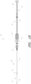
- FIG. 1A illustrates an access device 20 that is configured to be inserted into a blood vessel (e.g., a vein or an artery) in accordance with a preferred embodiment of the access device 20.
- a blood vessel e.g., a vein or an artery
- the access device 20 is described below in this context (i.e., for vascular access), the access device 20 also can be used to access and place the medical article into other locations within a patient's body (e.g., a drainage site) and for other purposes (e.g., for draining an abscess).
- a medical provider may wish to introduce a catheter and/or sheath into a space within a patient's body, for example, a blood vessel or drainage site, to introduce fluids to the space or remove fluids from the space.
- Various access devices are known in the art. Examples of an improved access device are described in PCT Application No. PCT/US2012/039740, entitled “ACCESS DEVICE,” filed May 25, 2012 .
- the present embodiment of the access device is disclosed in the context of placing an exemplary single-piece, medical article into a body space within a patient. Once placed, the medical article can then be used to receive other medical articles (e.g., guidewires) to provide access into the body space and/or be used to provide a passage way for introducing fluids into the body space or removing (e.g., draining) fluids from the body space.
- the medical article is a sheath 26 or catheter that is configured primarily to provide a fluid passage into a vein.
- the principles of the present invention are not limited to the placement of single piece sheaths or catheters, or to the subsequent insertion of a medical article via the sheath or catheter.
- the access device disclosed herein also can be successfully utilized in connection with placing one or more other types of medical articles, including other types of sheaths, fluid drainage and delivery tubes, and single or multi-lumen catheters directly in the patient or indirectly via another medical article.
- the access device disclosed herein can also be configured to directly or indirectly place central venous catheters, peripherally inserted central catheters, hemodialysis catheters, surgical drainage tubes, tear-away sheaths, multi-piece sheaths, PICC lines, IV lines, scopes, as well as electrical conduit for wires or cables connected to external or implanted electronic devices or sensors.
- the medical articles listed above may be directly placed in the patient via the dilator, needle, and guidewire of the access device or subsequently placed within the patient via a medical article that was placed within the patient via the dilator, needle, and guidewire of the access device.
- the embodiments disclosed herein are not limited to co-axial insertion of a single medical article.
- two catheters may be inserted in the patient via an inserted sheath or a second catheter may be inserted in the patient via an inserted first catheter.
- the medical article inserted via the dilator, needle, and guidewire can form a lumen that is in addition to the lumen(s) of the subsequently inserted medical article.
- the illustration and description of the access device in connection with a sheath is merely exemplary of one possible application of the access device.
- FIGS. 1A and 1B illustrate a preferred embodiment of an access device 20.
- the access device 20 includes a needle 22, a dilator 24, and a sheath 26.
- the access device also includes a guidewire section 28 and a track 30.
- the dilator 24 can be coaxially mounted on the needle 22, and the sheath 26 can be coaxially mounted on the dilator 24.
- the telescoping nature of the access device's components can also be accomplished by arranging the components with their axes arranged substantially parallel rather than coaxially (e.g., a monorail-type design).
- the dilator 24 and/or sheath 26 can slide distally over the needle 32 for insertion into a cavity and the needle hub 34 can slide relatively along the track 30.
- each of these components can include a luminal fitting at a terminal end or transition (e.g., a hub) and elongated structure that extends from the fitting.
- the needle 22 includes a needle body 32 that extends distally from the needle hub 34
- the dilator 24 includes a dilator shaft 36 that extends distally from a dilator hub 38
- the sheath 26 includes a sheath body 40 that extends distally from a sheath hub 42.
- the guidewire section 28 can include a guidewire 44 and preferably a guidewire hub or cap 46.
- the guidewire hub 46 is disposed on the proximal end of the guidewire 44; however, in other applications, the hub 46 can be disposed at a location between the ends of the guidewire 44.
- the needle body 32 can have a sufficiently long length to access a targeted subcutaneous body space and can have a sufficient gauge size to withstand the insertion forces when accessing the body space without causing undue trauma.
- the needle body can have a length between 3- 20 cm, and more preferably between 3-10 cm.
- the needle body 32 preferably has a length of 7 cm or greater, and more preferably has a length of 9 cm or greater, and most preferably has a length of 9 to 10 cm.
- the size of the needle preferably is 18 gauge or smaller, and more preferably between 18-28 gauge, and most preferably between 18-26 gauge for micro-puncture applications (e.g., peripheral IVs).
- the length and gauge of the needle body 32 should be significantly shorter and smaller, for example preferably between 3-4 cm and between 26-28 gauge.
- the guidewire 44 can be introduced through a hollow and preferably tapered portion of the needle hub 34, through the needle body 32, and into a punctured vessel.
- the tapered portion can guide the guidewire 44 toward the bore of the needle 22. Further, in some embodiments this tapered portion can provide a female luer connection.
- the guidewire 44 allows the healthcare provider to guide the dilator 24 and sheath 26 into the vessel.
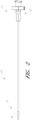
- FIG. 2 is a plan view of the dilator 24 of the embodiment depicted in FIG. 1A .
- the illustrated dilator 24 can include a dilator shaft 36, a dilator hub 38, a distal region 70, and a proximal region 72.
- the dilator hub 38 can be a fitting at a terminal end supporting the dilator shaft 36.
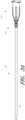
- FIG. 3A is a plan view of the sheath 26 of the embodiment depicted in FIG. 1A .
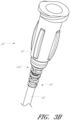
- FIG. 3B is an enlarged perspective view of the sheath hub 42 of the sheath 26 of FIG. 3A .
- the sheath 26 can include a sheath body 40 and a sheath hub 42.
- the sheath body 40 may be made partially or completely from clear, translucent, transparent, or semi-opaque material.
- the sheath hub 42 can be a fitting at a terminal end supporting the sheath body 40.
- the sheath 26 can have relief elements 140, best illustrated in FIG. 3B , extending from the sheath hub 42 (e.g., a distal portion of the sheath hub 42).
- the relief elements 140 can be disposed about a proximal portion 92 of the sheath body 40, to provide support to the proximal portion 92 of the sheath body 40 when the proximal portion 92 flexes with respect to the sheath hub 42.
- the relief element 140 can include a variety of shapes and structures to provide additional support to sheath body 40 while still providing some flexibility thereto.
- the relief element 140 can include a substantially hollow elongated member, an approximately rectangular or cylindrical tubular shape, and can be configured with a wall thickness and material that provide some support and flexibility.
- the relief element 140 can be configured with a substantially continuous or unbroken surface, or can include gaps, apertures, recessions, or other structure extending partially or completely through its surface to provide additional flexibility against kinking.
- the relief element 140 can include various support structures such as circumferential or longitudinal (axial) ribs, struts, and the like.
- the relief element is absent.
- Improved patency of the bent medical article e.g., the sheath
- a short outer sleeve can extend from the sheath hub to the sheath shaft to form a relatively smooth transition region.
- the sheath body 40 can be a single piece sheath through which fluid (e.g., an IV solution or imaging solution) is introduced into the vessel or withdrawn from the vessel.
- the sheath body 40 is an extended dwell (e.g., up to 29 days) peripheral catheter of 4 or 5 French having a single lumen with a length of about 80mm.
- the sheath body 40 alternatively can be a single or multi-piece body through which other medical devices are introduced into the vessel.
- a catheter or other medical article e.g., a guidewire
- the sheath body 40 forms a conduit for insertion of the catheter or other medical article (e.g., a guidewire).
- the sheath body 40 can be split along its length to ease removal of the sheath once the catheter or other medical article (e.g., PICC) has been placed in the patient.
- the sheath or a portion of the sheath can, in addition to providing a conduit, form a lumen that is in addition to the lumen(s) of the catheter.
- an equivalent to a triple lumen catheter can be formed by inserting a dual lumen catheter through the sheath body 40 with the sheath body 40 itself forming a third lumen.
- prior forms of the sheath body 40 could over-flex, kink, and/or permanently deform, which would reduce or inhibit its functionality.
- Prior sheath body 40 would thus be susceptible to such kinking or permanent deformation, for example, at the interface between sheath body 40 and the sheath hub 42, or at portions upstream or downstream of the interface between sheath body 40 and the sheath hub 42.
- a kink or permanent deformation would inhibit the flow of fluid, such as blood or medicine, through sheath body 40.
- sheath 26 can include various materials and an optional relief element 140, as described above, that can provide support to sheath 26.
- the sheath can be made of a material with sufficient flexibility to facilitate the insertion of the sheath into a patient and fluid transfers through the sheath.
- the sheath can be made of a material that varies in flexibility depending on the environment to which it is exposed.
- the sheath can be made of a material that varies in flexibility and/or rigidity based upon the temperature to which the sheath is exposed.
- the sheath can be made of a material that has a reduced rigidity and/or increased flexibility upon exposure to heat, e.g., a temperature increase.
- the sheath can be made of a urethane polycarbonate, or another form of urethane, or another plastic or non-plastic material that provides similar properties (such as a similar modulus of elasticity, modulus of rigidity (shear modulus), and/or bulk modulus).
- the sheath can absorb heat from the body of a patient or from other heat sources, and in response, reduce its rigidity. Such reduced rigidity can increase comfort to the patient, and/or reduce the likelihood of injury or tissue damage to the patient during the insertion and use of the sheath.
- the sheath body 40 can be made of a material capable of withstanding the relative high pressures (e.g., 2068 kPa) and flow rates (e.g., 130 ml/min.) associated with power injection.
- bio-compatible materials that can be used for the sheath body 40, and that can include one or more of the properties described herein, such as flexibility, power injectable, and/or increased flexibility upon exposure to heat, are manufactured by AdvanSource Biomaterials Corp. (e.g., ChronoFlex C ® ) and Lubrizol (e.g., Carbothane TPU ® ).
- AdvanSource Biomaterials Corp. e.g., ChronoFlex C ®
- Lubrizol e.g., Carbothane TPU ®
- the sheath material can still kink when bent to a certain extent, for example, about 90 degrees.
- the method described herein can advantageously produce sheaths having improved flexibility, memory, kink-resistance and/or resilience.
- a sheath can be formed by extruding a selected material, for example, a polycarbonate-urethane copolymer as described herein, to form a medical article or tube and then annealing the extruded tube.
- a selected material for example, a polycarbonate-urethane copolymer as described herein
- Some polymers can be formed to include a mixture of crystalline regions and amorphous regions. Annealing can generally increase the crystallinity of a material and can involve heating the material to a temperature below its melting point, maintaining that temperature for a time period, and then cooling the material. The heat can provide energy to break existing bonds in the material so that atoms in the material can diffuse, redistribute, and form new bonds to create a more crystalline or organized structure.
- an extruded tube can be annealed by heating the tube to a temperature of about 120°C and maintaining the temperature for about one hour. Other durations and temperatures below the selected material's melting point are also possible.
- Annealing can be used to change a material's structural or mechanical properties, such as strength and hardness. Annealing typically results in a more rigid material due to the increased crystallinity.
- a polycarbonate-urethane copolymer extruded tube as described herein was annealed under certain conditions, the tube was found to have improved kink-resistance.
- a tube extruded and annealed according to embodiments of the present disclosure was able to bend up to about 120 degrees before kinking.
- the process described herein can therefore be used to increase the flexibility of the tube. Alternatively or additionally, the process may provide the tube with greater kink or crease-resistance properties.
- a method of using a medical article having a flexible shaft made of annealed urethane polycarbonate includes inserting the shaft into a vessel over a guidewire, withdrawing the guidewire, and bending the shaft to lie substantially parallel to the skin, and retaining the shaft in the bent position without kinking the shaft.
- the shaft may be bent to lie across the skin so that it can be secured to the skin (e.g. with tape or another securement device) during use without kinking.
- the extruded tube can be cut into desired lengths before or after annealing.
- the annealing process may alter the tube dimensions to some extent, for example, the tube may shrink slightly. Therefore, in some embodiments, if the extruded tube is cut before annealing, possible changes in dimension due to subsequent annealing are taken into account when cutting the tube. Additionally or alternatively, the tube can be rough cut before annealing and then trimmed to its desired length (e.g., 80 mm) afterward.
- Methods for forming a more flexible or more kink-resistant tube as described herein can be used to form tubes for numerous applications.
- the method can be used to form a sheath for a vascular access device as described herein.
- the method can include additional steps to shape the tube for use.
- the method can include flaring an end of the tube. This end is configured to be outside of the patient in use. The flare can then be over-molded onto a hub that will be part of the access device.
- the method can also or alternatively include forming an end of the tube into a tip. This end is configured to be inserted into the patient in use.
- FIG. 4 illustrates an example method 200 of forming a flexible medical article as described herein.
- the method 200 includes forming a section of material out of a selected polymer.
- the section can be made by an extrusion process as illustrated in operation block 202.
- the flexible material article can be made by injection molding, compression molding, or similar techniques.
- a method for forming the flexible medical article includes extruding a polymer, for example, a polycarbonate-urethane copolymer or another form of urethane, to form a tubular shaft with at least one lumen.
- the flexible medical article can be made without a lumen.
- raw polymeric material can be melt processed into a barrel of an extruder.
- the polymeric material can be made a polycarbonate-urethane copolymer or another form of urethane. It should be appreciated that one or more polymers or a composite polymer can be used in conjunction with formation method 200.
- Melt processing can occur by taking raw material in the form of nurdles or small beads and gravity feeding them from a top mounted hopper into the barrel of the extruder. Once inside the barrel, the material can come in contact with a rotating screw, forcing the polymeric material forward into the barrel. Heaters in the barrel and/or the pressure and friction within the barrel can heat the polymeric material to a desired melt temperature.
- the melted material can leave the screw and enter into a die used to form the tubular cross-section.
- a hollow cross-section for the tubular member can be extruded by placing one or more pins inside of the die to produce a desired number of lumens.
- the size and shape of the lumens can be adjusted by size and shape of the pins as well as by adding positive pressure to the individual pins.
- the method can include heat treating the tube by annealing, as illustrated in operation block 204, to improve the kink or crease-resistance properties of the tube.
- Annealing can involve heating the material to a temperature below its melting point, maintaining that temperature for a time period, and then cooling the material.
- an extruded tube can be annealed by heating the tube to a temperature of about 120 °C and maintaining the temperature for about one hour. Other durations and temperatures below the selected material's melting point are also possible.
- a tube extruded and annealed according to embodiments of the present disclosure can bend up to about 120 degrees without kinking.
- a tube extruded and annealed according to the embodiments of the present disclosure can withstand pressures up to 2068 kPa and flow rates of up to 130 ml/min.
- the polymer has increased flexibility (i.e., reduced rigidity) upon exposure to heat.
- the method can include sizing the tubing as illustrated in operation block 206.
- Sizing of the tubing can be done by cutting, machining, abrasive processing (e.g., grinding or etching), or the like.
- the tubing can be further processed (e.g., be polished or sanded) to remove any sharp edges or burrs.
- the sizing of the tubing can be performed either before or after the annealing step illustrated in operation block 206. As described above, the annealing process may alter the dimensions of the tube (e.g., shrinkage).
- the tube can be rough cut to an approximate size before annealing and then trimmed to its desired length (e.g., 80 mm) after annealing.
- the method 200 can also include flaring an end of the tube as illustrated in operation block 208.
- the flared end can then be over-molded onto a hub that will be part of the access device.
- the method 200 can include forming an end of the tube into a tip (e.g., the opposite end of the flared end of the tube) as illustrated in operation block 210. This end is configured to be inserted into the patient in use.
- tube tubular
- tubular tubular
- structures having at least one lumen including structures that have (i) one or more lumens (e.g., multiple lumens); (ii) one or more lumens offset from a central longitudinal axis of the structure; (iii) a single lumen structure having a generally uniform wall thickness; and (iv) a single lumen that is coaxial with a central longitudinal of the structure.
- a method for forming at least a portion of a flexible medical article comprising: extruding a polymer to form said portion of the medical article; and annealing said portion of the medical article.
- the annealing may comprise annealing said portion of the medical article at about 120°C for about one hour.
- the polymer may comprise urethane.
- the polymer may be selected to have the property of reduced rigidity when exposed to heat.
- the polymer may comprise urethane polycarbonate.
- the method may further comprise cutting said portion of the medical article.
- the method may further comprise flaring an end of said portion of the medical article so that the end is configured to be coupled to a hub of the medical article.
- the method may further comprise over-molding the end of the portion of the medical article onto the hub.
- the method may further comprise forming an end of the portion of the medical article into a tip.
- a medical article having a flexible, tubular shaft with at least one lumen, the shaft being formed by a process comprising: extruding a polymer to form at least the tubular shaft of the medical article; and annealing the tubular shaft.
- the annealing may comprise annealing the tubular shaft of the medical article at about 120°C for about one hour.
- the tubular shaft may be annealed sufficiently so as to be capable of bending up to about 120° without kinking.
- the polymer may comprise a polycarbonate-urethane copolymer.
- the polymer may be capable of withstanding pressures up to 2068 kPa.
- the polymer may be capable of withstanding flow rates of up to 130 ml/min.
- the polymer may have increased flexibility upon exposure to heat.
- the medical article may additionally comprise a hub from which the shaft extends.
- the medical article may additionally comprise a needle having a needle shaft and a needle hub, a dilator having a dilator shaft and a dilator hub, and a guidewire, wherein the dilator shaft is coaxially disposed on the needle shaft with the needle hub and dilator hub juxtaposed, the guidewire is at least partially disposed in the needle, and the shaft is coaxially disposed on the dilator shaft with the hub juxtaposed the dilator hub.
- the medical article may additionally comprise a track along which the needle hub travels, the track being attached to the dilator hub.
- a method of using a medical article having a flexible shaft comprising annealed urethane polycarbonate comprising inserting the shaft into a vessel over a guidewire, withdrawing the guidewire, and bending the shaft to lie substantially parallel to the skin, and retaining the shaft in the bent position without kinking the shaft.
Abstract
Description
- This application claims the benefit of priority under 35 U.S.C. 9 119(e) of
U.S. Provisional Application Number 13/420,343 filed on March 14, 2012 - The present disclosure is generally directed to methods for making a medical article (for example, catheters, cannulas, and sheaths) for the introduction and/or delivery into a body space, such as, for example, an artery, vein, vessel, body cavity, or drainage site. The disclosure is also directed to such medical articles and to access devices that place such medical articles into an artery, vein, vessel, body cavity, or drainage site.
- Various medical articles, for example, catheters, cannulas, sheaths, etc., are often introduced into a patient, for example, in an artery, vein, body cavity, or drainage site, to deliver fluids to, or withdraw fluids from, the patient. For example, a catheter or vascular sheath can be introduced into a patient's blood vessel using the Seldinger or a modified Seldinger technique. These techniques involve inserting an access needle into the patient's blood vessel and then inserting a guidewire through the needle and into the vessel. The needle is removed, and a dilator and sheath, either separately, or in combination, are inserted over the guidewire, through tissue, and into the vessel. The dilator and guidewire are then removed and discarded. The sheath can be left in the vessel, for example, to deliver medical fluids to the patient, or a catheter or other medical article can be inserted through the sheath into the vessel to a desired location. For instance,
US 2001/0001113A1 discloses an intravascular catheter system for implanting a stent in a body lumen using a balloon manufactured by a series of steps comprising annealing and cutting of a shaft. Another example of an access device is shown inUS 2008/026431A1 . - A medical provider may need to bend and manipulate the sheath and/or catheter during insertion and/or after insertion during use. Although some existing sheaths and catheters have some flexibility to allow for such manipulation, existing devices may kink when bent to a certain radius of curvature, for example, a 90 degree bend. When medical articles kink, they can disrupt the flow of fluids within the device and hinder performance of the device. Additionally, some sheaths and catheters are more prone to re-kink or re-crease after initially kinking and may subsequently kink at an earlier point, for example, at a smaller angle of bending.
- In view of the foregoing, there is a need for an improved medical article and method of making such a medical article with improved flexibility, memory, kink-resistance, and/or resilience.
- In some embodiments, a method for forming a flexible medical article includes extruding a polymer, for example, a polycarbonate-urethane copolymer or another form of urethane. The method can further include heat treating the flexible medical article by annealing under conditions of, for example, 248°F for one hour. In some embodiments, the polymer is selected have the property of reduced rigidity (i.e., increased flexibility) when exposed to heat. The method can further include cutting the medical article into desired lengths before and/or after annealing. Optionally, the method can also include flaring one end of the medical article to be coupled to a hub and over-molding the flared end onto the hub and/or forming one end of the medical article into a tip.
- In some embodiments, a method for forming a flexible medical article includes extruding a polymer, for example, a polycarbonate-urethane copolymer or another form of urethane, to form a tubular shaft with at least one lumen. The method can further include heat treating the tubular shaft by annealing under conditions of, for example, 120 °C for one hour. In some embodiments, the polymer is selected have the property of reduced rigidity (i.e., increased flexibility) when exposed to heat. The method can further include cutting the tubular shaft into desired lengths before and/or after annealing. The method can also include flaring one end of the tubular shaft to be coupled to a hub and over-molding the flared end onto the hub and/or forming one end of the tube into a tip. In one embodiment, the tubular shaft is annealed sufficiently so as to be capable of bending up to about 120° without kinking. In another embodiment, the polymer is capable of withstanding pressures up to 2068 kPa and flow rates of up to 130ml/min.
- In some embodiments, a flexible medical article or tube which can be used as, for example, a sheath or catheter to be introduced into a body lumen of a patient is formed by extruding a polymer to form a tube and annealing the tube.
- In one embodiment, the flexible medical article additionally comprises a needle having a needle shaft and a needle hub, a dilator having a dilator shaft and a dilator hub, and a guidewire, wherein the dilator shaft is coaxially disposed on the needle shaft with the needle hub and dilator hub juxtaposed, the guidewire is at least partially disposed in the needle, and the shaft is coaxially disposed on the dilator shaft with the hub juxtaposed the dilator hub.
- In one embodiment, a method of using a medical article having a flexible shaft comprising annealed urethane polycarbonate comprises inserting the shaft into a vessel over a guidewire, withdrawing the guidewire, and bending the shaft to lie substantially parallel to the skin, and retaining the shaft in the bent position without kinking the shaft.
- The foregoing and other features, aspects, and advantages of the method of making a medical article and corresponding medical article are described in detail below with reference to the drawings of various embodiments, which are intended to illustrate and not to limit the embodiments of the invention. The drawings comprise the following figures of one embodiment, in which:
-
FIG. 1A is a perspective view of an embodiment of an access device. -
FIG. 1B is a plan view of the embodiment depicted inFIG. 1A . -
FIG. 2 is a plan view of a dilator fromFIG. 1A . -
FIG. 3A is a plan view of a sheath fromFIG. 1A and shows a sheath hub connected to a proximal end of a sheath. -
FIG. 3B is an enlarged perspective view of a proximal portion of the sheath fromFIG. 3A . -
FIG. 4 shows a flow chart of an example method for forming a vascular sheath. - Embodiments of the invention will now be described with reference to the accompanying figures, wherein like numerals refer to like elements throughout the following description and drawings. Although several embodiments, examples and illustrations are disclosed below, it will be understood by those of ordinary skill in the art that the invention described herein extends beyond the specifically disclosed embodiments, examples and illustrations and can include other uses of the invention and obvious modifications and equivalents thereof. The terminology used in the description presented herein is not intended to be interpreted in any limited or restrictive manner simply because it is being used in conjunction with a detailed description of certain specific embodiments of the invention. In addition, embodiments of the invention can comprise several novel features and no single feature is solely responsible for its desirable attributes or is essential to practicing the inventions herein described.
- The present disclosure provides a medical article (e.g., a catheter, cannula, or sheath) that can be delivered into a space, such as a blood vessel or drainage site, by an access device.
FIG. 1A illustrates anaccess device 20 that is configured to be inserted into a blood vessel (e.g., a vein or an artery) in accordance with a preferred embodiment of theaccess device 20. While theaccess device 20 is described below in this context (i.e., for vascular access), theaccess device 20 also can be used to access and place the medical article into other locations within a patient's body (e.g., a drainage site) and for other purposes (e.g., for draining an abscess). - In various circumstances a medical provider may wish to introduce a catheter and/or sheath into a space within a patient's body, for example, a blood vessel or drainage site, to introduce fluids to the space or remove fluids from the space. Various access devices are known in the art. Examples of an improved access device are described in PCT Application No.
PCT/US2012/039740, entitled "ACCESS DEVICE," filed May 25, 2012 . - The present embodiment of the access device is disclosed in the context of placing an exemplary single-piece, medical article into a body space within a patient. Once placed, the medical article can then be used to receive other medical articles (e.g., guidewires) to provide access into the body space and/or be used to provide a passage way for introducing fluids into the body space or removing (e.g., draining) fluids from the body space. In the illustrated embodiment in
FIG. 1A , the medical article is asheath 26 or catheter that is configured primarily to provide a fluid passage into a vein. The principles of the present invention, however, are not limited to the placement of single piece sheaths or catheters, or to the subsequent insertion of a medical article via the sheath or catheter. Instead, it will be understood in light of the present disclosure that the access device disclosed herein also can be successfully utilized in connection with placing one or more other types of medical articles, including other types of sheaths, fluid drainage and delivery tubes, and single or multi-lumen catheters directly in the patient or indirectly via another medical article. - For example, but without limitation, the access device disclosed herein can also be configured to directly or indirectly place central venous catheters, peripherally inserted central catheters, hemodialysis catheters, surgical drainage tubes, tear-away sheaths, multi-piece sheaths, PICC lines, IV lines, scopes, as well as electrical conduit for wires or cables connected to external or implanted electronic devices or sensors. As explained above, the medical articles listed above may be directly placed in the patient via the dilator, needle, and guidewire of the access device or subsequently placed within the patient via a medical article that was placed within the patient via the dilator, needle, and guidewire of the access device.
- Further, the embodiments disclosed herein are not limited to co-axial insertion of a single medical article. For example, two catheters may be inserted in the patient via an inserted sheath or a second catheter may be inserted in the patient via an inserted first catheter. Further, in addition to providing a conduit into the vessel or other body space, the medical article inserted via the dilator, needle, and guidewire can form a lumen that is in addition to the lumen(s) of the subsequently inserted medical article. One skilled in the art can also find additional applications for the devices and systems disclosed herein. Thus, the illustration and description of the access device in connection with a sheath (e.g., for micro puncture applications) is merely exemplary of one possible application of the access device.
-
FIGS. 1A and1B illustrate a preferred embodiment of anaccess device 20. Theaccess device 20 includes aneedle 22, adilator 24, and asheath 26. In the illustrated embodiment, the access device also includes aguidewire section 28 and atrack 30. As best seen inFIG. 1B , thedilator 24 can be coaxially mounted on theneedle 22, and thesheath 26 can be coaxially mounted on thedilator 24. The telescoping nature of the access device's components can also be accomplished by arranging the components with their axes arranged substantially parallel rather than coaxially (e.g., a monorail-type design). In use, thedilator 24 and/orsheath 26 can slide distally over theneedle 32 for insertion into a cavity and theneedle hub 34 can slide relatively along thetrack 30. - Each of these components can include a luminal fitting at a terminal end or transition (e.g., a hub) and elongated structure that extends from the fitting. Thus, in the illustrated embodiment, the
needle 22 includes aneedle body 32 that extends distally from theneedle hub 34, thedilator 24 includes adilator shaft 36 that extends distally from adilator hub 38, and thesheath 26 includes asheath body 40 that extends distally from asheath hub 42. Theguidewire section 28 can include aguidewire 44 and preferably a guidewire hub orcap 46. In the illustrated embodiment, theguidewire hub 46 is disposed on the proximal end of theguidewire 44; however, in other applications, thehub 46 can be disposed at a location between the ends of theguidewire 44. - The
needle body 32 can have a sufficiently long length to access a targeted subcutaneous body space and can have a sufficient gauge size to withstand the insertion forces when accessing the body space without causing undue trauma. For many applications, the needle body can have a length between 3- 20 cm, and more preferably between 3-10 cm. For example, to access a body space (e.g., a vessel) in the thorax of an adult human, theneedle body 32 preferably has a length of 7 cm or greater, and more preferably has a length of 9 cm or greater, and most preferably has a length of 9 to 10 cm. The size of the needle preferably is 18 gauge or smaller, and more preferably between 18-28 gauge, and most preferably between 18-26 gauge for micro-puncture applications (e.g., peripheral IVs). For applications with a neonate, the length and gauge of theneedle body 32 should be significantly shorter and smaller, for example preferably between 3-4 cm and between 26-28 gauge. - As explained below in greater detail, the
guidewire 44 can be introduced through a hollow and preferably tapered portion of theneedle hub 34, through theneedle body 32, and into a punctured vessel. Advantageously, the tapered portion can guide theguidewire 44 toward the bore of theneedle 22. Further, in some embodiments this tapered portion can provide a female luer connection. Theguidewire 44 allows the healthcare provider to guide thedilator 24 andsheath 26 into the vessel. -
FIG. 2 is a plan view of thedilator 24 of the embodiment depicted inFIG. 1A . As shown inFIG. 2 , the illustrateddilator 24 can include adilator shaft 36, adilator hub 38, adistal region 70, and aproximal region 72. As described above, thedilator hub 38 can be a fitting at a terminal end supporting thedilator shaft 36. -
FIG. 3A is a plan view of thesheath 26 of the embodiment depicted inFIG. 1A .FIG. 3B is an enlarged perspective view of thesheath hub 42 of thesheath 26 ofFIG. 3A . As shown inFIGS. 3A and3B , thesheath 26 can include asheath body 40 and asheath hub 42. Thesheath body 40 may be made partially or completely from clear, translucent, transparent, or semi-opaque material. As described above, thesheath hub 42 can be a fitting at a terminal end supporting thesheath body 40. - In some embodiments, the
sheath 26 can haverelief elements 140, best illustrated inFIG. 3B , extending from the sheath hub 42 (e.g., a distal portion of the sheath hub 42). Therelief elements 140 can be disposed about aproximal portion 92 of thesheath body 40, to provide support to theproximal portion 92 of thesheath body 40 when theproximal portion 92 flexes with respect to thesheath hub 42. - The
relief element 140 can include a variety of shapes and structures to provide additional support tosheath body 40 while still providing some flexibility thereto. For example, therelief element 140 can include a substantially hollow elongated member, an approximately rectangular or cylindrical tubular shape, and can be configured with a wall thickness and material that provide some support and flexibility. Therelief element 140 can be configured with a substantially continuous or unbroken surface, or can include gaps, apertures, recessions, or other structure extending partially or completely through its surface to provide additional flexibility against kinking. Therelief element 140 can include various support structures such as circumferential or longitudinal (axial) ribs, struts, and the like. - In other embodiments, the relief element is absent. Improved patency of the bent medical article (e.g., the sheath) is obtained by the annealing process described below. In such embodiments, a short outer sleeve can extend from the sheath hub to the sheath shaft to form a relatively smooth transition region.
- The
sheath body 40 can be a single piece sheath through which fluid (e.g., an IV solution or imaging solution) is introduced into the vessel or withdrawn from the vessel. In one form, thesheath body 40 is an extended dwell (e.g., up to 29 days) peripheral catheter of 4 or 5 French having a single lumen with a length of about 80mm. Thesheath body 40 alternatively can be a single or multi-piece body through which other medical devices are introduced into the vessel. For example, a catheter or other medical article (e.g., a guidewire) can be inserted into the vessel through the sheath body. In such an embodiment, thesheath body 40 forms a conduit for insertion of the catheter or other medical article (e.g., a guidewire). In some embodiments, thesheath body 40 can be split along its length to ease removal of the sheath once the catheter or other medical article (e.g., PICC) has been placed in the patient. In some embodiment, the sheath or a portion of the sheath can, in addition to providing a conduit, form a lumen that is in addition to the lumen(s) of the catheter. For example, an equivalent to a triple lumen catheter can be formed by inserting a dual lumen catheter through thesheath body 40 with thesheath body 40 itself forming a third lumen. - During or after the insertion of
sheath 26 into a patient, prior forms of thesheath body 40 could over-flex, kink, and/or permanently deform, which would reduce or inhibit its functionality.Prior sheath body 40 would thus be susceptible to such kinking or permanent deformation, for example, at the interface betweensheath body 40 and thesheath hub 42, or at portions upstream or downstream of the interface betweensheath body 40 and thesheath hub 42. A kink or permanent deformation would inhibit the flow of fluid, such as blood or medicine, throughsheath body 40. Additionally, ifaccess device 20 were used, for example, for IV lines, PICC lines, and other higher pressure applications, the proximal end ofsheath body 40 could move erratically in a "whipping" motion as the pressurized fluid flows throughsheath 26. To reduce the likelihood of such kinking or permanent deformation withinsheath body 40, and/or to reduce the likelihood of such whipping during the deployment ofaccess device 20, in some embodiments,sheath 26 can include various materials and anoptional relief element 140, as described above, that can provide support tosheath 26. - In some embodiments, the sheath can be made of a material with sufficient flexibility to facilitate the insertion of the sheath into a patient and fluid transfers through the sheath. In some embodiments, the sheath can be made of a material that varies in flexibility depending on the environment to which it is exposed. For example, the sheath can be made of a material that varies in flexibility and/or rigidity based upon the temperature to which the sheath is exposed. In some embodiments, the sheath can be made of a material that has a reduced rigidity and/or increased flexibility upon exposure to heat, e.g., a temperature increase. In some embodiments, the sheath can be made of a urethane polycarbonate, or another form of urethane, or another plastic or non-plastic material that provides similar properties (such as a similar modulus of elasticity, modulus of rigidity (shear modulus), and/or bulk modulus). In such embodiments, during the insertion of the sheath into a patient, the sheath can absorb heat from the body of a patient or from other heat sources, and in response, reduce its rigidity. Such reduced rigidity can increase comfort to the patient, and/or reduce the likelihood of injury or tissue damage to the patient during the insertion and use of the sheath. In some embodiments, the
sheath body 40 can be made of a material capable of withstanding the relative high pressures (e.g., 2068 kPa) and flow rates (e.g., 130 ml/min.) associated with power injection. - Examples of bio-compatible materials that can be used for the
sheath body 40, and that can include one or more of the properties described herein, such as flexibility, power injectable, and/or increased flexibility upon exposure to heat, are manufactured by AdvanSource Biomaterials Corp. (e.g., ChronoFlex C®) and Lubrizol (e.g., Carbothane TPU®). In some cases, even when the sheath material is selected to have certain properties, such as flexibility, the sheath can still kink when bent to a certain extent, for example, about 90 degrees. The method described herein can advantageously produce sheaths having improved flexibility, memory, kink-resistance and/or resilience. - In some embodiments, a sheath can be formed by extruding a selected material, for example, a polycarbonate-urethane copolymer as described herein, to form a medical article or tube and then annealing the extruded tube. Some polymers can be formed to include a mixture of crystalline regions and amorphous regions. Annealing can generally increase the crystallinity of a material and can involve heating the material to a temperature below its melting point, maintaining that temperature for a time period, and then cooling the material. The heat can provide energy to break existing bonds in the material so that atoms in the material can diffuse, redistribute, and form new bonds to create a more crystalline or organized structure. In some embodiments, an extruded tube can be annealed by heating the tube to a temperature of about 120°C and maintaining the temperature for about one hour. Other durations and temperatures below the selected material's melting point are also possible.
- Annealing can be used to change a material's structural or mechanical properties, such as strength and hardness. Annealing typically results in a more rigid material due to the increased crystallinity. However, when a polycarbonate-urethane copolymer extruded tube as described herein was annealed under certain conditions, the tube was found to have improved kink-resistance. For example, a tube extruded and annealed according to embodiments of the present disclosure was able to bend up to about 120 degrees before kinking. The process described herein can therefore be used to increase the flexibility of the tube. Alternatively or additionally, the process may provide the tube with greater kink or crease-resistance properties.
- In one embodiment, a method of using a medical article having a flexible shaft made of annealed urethane polycarbonate includes inserting the shaft into a vessel over a guidewire, withdrawing the guidewire, and bending the shaft to lie substantially parallel to the skin, and retaining the shaft in the bent position without kinking the shaft. In such an embodiment, once the shaft is placed into a vessel, the shaft may be bent to lie across the skin so that it can be secured to the skin (e.g. with tape or another securement device) during use without kinking.
- The extruded tube can be cut into desired lengths before or after annealing. The annealing process may alter the tube dimensions to some extent, for example, the tube may shrink slightly. Therefore, in some embodiments, if the extruded tube is cut before annealing, possible changes in dimension due to subsequent annealing are taken into account when cutting the tube. Additionally or alternatively, the tube can be rough cut before annealing and then trimmed to its desired length (e.g., 80 mm) afterward.
- Methods for forming a more flexible or more kink-resistant tube as described herein can be used to form tubes for numerous applications. For example, the method can be used to form a sheath for a vascular access device as described herein. For this and other similar applications, the method can include additional steps to shape the tube for use. For example, the method can include flaring an end of the tube. This end is configured to be outside of the patient in use. The flare can then be over-molded onto a hub that will be part of the access device. The method can also or alternatively include forming an end of the tube into a tip. This end is configured to be inserted into the patient in use.
-
FIG. 4 illustrates anexample method 200 of forming a flexible medical article as described herein. Themethod 200 includes forming a section of material out of a selected polymer. The section can be made by an extrusion process as illustrated inoperation block 202. In alternative embodiments, the flexible material article can be made by injection molding, compression molding, or similar techniques. In some embodiments, a method for forming the flexible medical article includes extruding a polymer, for example, a polycarbonate-urethane copolymer or another form of urethane, to form a tubular shaft with at least one lumen. In another embodiment, the flexible medical article can be made without a lumen. - With reference to
FIG. 4 , in atubular extrusion process 202, raw polymeric material can be melt processed into a barrel of an extruder. In some embodiments, the polymeric material can be made a polycarbonate-urethane copolymer or another form of urethane. It should be appreciated that one or more polymers or a composite polymer can be used in conjunction withformation method 200. Melt processing can occur by taking raw material in the form of nurdles or small beads and gravity feeding them from a top mounted hopper into the barrel of the extruder. Once inside the barrel, the material can come in contact with a rotating screw, forcing the polymeric material forward into the barrel. Heaters in the barrel and/or the pressure and friction within the barrel can heat the polymeric material to a desired melt temperature. At the front of the barrel, the melted material can leave the screw and enter into a die used to form the tubular cross-section. A hollow cross-section for the tubular member can be extruded by placing one or more pins inside of the die to produce a desired number of lumens. The size and shape of the lumens can be adjusted by size and shape of the pins as well as by adding positive pressure to the individual pins. - With continued reference to
FIG. 4 , once the polymer tube has been formed, the method can include heat treating the tube by annealing, as illustrated inoperation block 204, to improve the kink or crease-resistance properties of the tube. Annealing can involve heating the material to a temperature below its melting point, maintaining that temperature for a time period, and then cooling the material. In some embodiments, an extruded tube can be annealed by heating the tube to a temperature of about 120°C and maintaining the temperature for about one hour. Other durations and temperatures below the selected material's melting point are also possible. In one embodiment a tube extruded and annealed according to embodiments of the present disclosure can bend up to about 120 degrees without kinking. In another embodiment, a tube extruded and annealed according to the embodiments of the present disclosure can withstand pressures up to 2068 kPa and flow rates of up to 130 ml/min. In some embodiments, the polymer has increased flexibility (i.e., reduced rigidity) upon exposure to heat. - With further reference to
FIG. 4 , in some embodiments, the method can include sizing the tubing as illustrated inoperation block 206. Sizing of the tubing can be done by cutting, machining, abrasive processing (e.g., grinding or etching), or the like. In one embodiment, following sizing of the tubing, the tubing can be further processed (e.g., be polished or sanded) to remove any sharp edges or burrs. The sizing of the tubing can be performed either before or after the annealing step illustrated inoperation block 206. As described above, the annealing process may alter the dimensions of the tube (e.g., shrinkage). Thus, if the tubing is sized prior to annealing, the dimensional changes due to annealing can be taken into account when sizing the tubing. Additionally or alternatively, the tube can be rough cut to an approximate size before annealing and then trimmed to its desired length (e.g., 80 mm) after annealing. - With continued reference to
FIG. 4 , in some embodiments, themethod 200 can also include flaring an end of the tube as illustrated inoperation block 208. The flared end can then be over-molded onto a hub that will be part of the access device. Additionally or alternatively, themethod 200 can include forming an end of the tube into a tip (e.g., the opposite end of the flared end of the tube) as illustrated inoperation block 210. This end is configured to be inserted into the patient in use. - As used herein, the terms "tube," "tubular," and the like are meant to be broad enough to refer to structures having at least one lumen, including structures that have (i) one or more lumens (e.g., multiple lumens); (ii) one or more lumens offset from a central longitudinal axis of the structure; (iii) a single lumen structure having a generally uniform wall thickness; and (iv) a single lumen that is coaxial with a central longitudinal of the structure. Conditional language used herein, such as, among others, "can," "could," "might," "may," "e.g.," and the like, unless specifically stated otherwise, or otherwise understood within the context as used, is generally intended to convey that certain embodiments include, while other embodiments do not include, certain features, elements and/or states. Thus, such conditional language is not generally intended to imply that features, elements and/or states are in any way required for one or more embodiments or that one or more embodiments necessarily include logic for deciding whether these features, elements and/or states are included or are to be performed in any particular embodiment.
- As an example, a method for forming at least a portion of a flexible medical article is disclosed, the method comprising: extruding a polymer to form said portion of the medical article; and annealing said portion of the medical article. In a further example, the annealing may comprise annealing said portion of the medical article at about 120°C for about one hour. The polymer may comprise urethane. The polymer may be selected to have the property of reduced rigidity when exposed to heat. The polymer may comprise urethane polycarbonate. The method may further comprise cutting said portion of the medical article. The method may further comprise flaring an end of said portion of the medical article so that the end is configured to be coupled to a hub of the medical article. The method may further comprise over-molding the end of the portion of the medical article onto the hub. The method may further comprise forming an end of the portion of the medical article into a tip.
- In further examples, a medical article is disclosed having a flexible, tubular shaft with at least one lumen, the shaft being formed by a process comprising: extruding a polymer to form at least the tubular shaft of the medical article; and annealing the tubular shaft. The annealing may comprise annealing the tubular shaft of the medical article at about 120°C for about one hour. The tubular shaft may be annealed sufficiently so as to be capable of bending up to about 120° without kinking. The polymer may comprise a polycarbonate-urethane copolymer. The polymer may be capable of withstanding pressures up to 2068 kPa. The polymer may be capable of withstanding flow rates of up to 130 ml/min. The polymer may have increased flexibility upon exposure to heat. The medical article may additionally comprise a hub from which the shaft extends. The medical article may additionally comprise a needle having a needle shaft and a needle hub, a dilator having a dilator shaft and a dilator hub, and a guidewire, wherein the dilator shaft is coaxially disposed on the needle shaft with the needle hub and dilator hub juxtaposed, the guidewire is at least partially disposed in the needle, and the shaft is coaxially disposed on the dilator shaft with the hub juxtaposed the dilator hub. The medical article may additionally comprise a track along which the needle hub travels, the track being attached to the dilator hub.
- In further examples, a method of using a medical article having a flexible shaft comprising annealed urethane polycarbonate is disclosed, the method comprising inserting the shaft into a vessel over a guidewire, withdrawing the guidewire, and bending the shaft to lie substantially parallel to the skin, and retaining the shaft in the bent position without kinking the shaft.
Claims (5)
- A medical article comprising a flexible, tubular shaft (26) with at least one lumen, and a hub (42), the tubular shaft (26) being formed by a method comprising steps of forming the tubular shaft (26) by extruding a polycarbonate urethane copolymer; and annealing the tubular shaft (26) to increase flexibility of said tubular shaft (26),the medical article further comprisinga dilator (24) disposed parallel to the flexible tubular shaft (26); anda needle (22) disposed parallel to the dilator (24).
- The medical article of Claim 1, wherein annealing comprises annealing the tubular shaft (24) of the medical article at about 120 °C for about one hour.
- The medical article of Claim 1, wherein the tubular shaft (24) is annealed sufficiently so as to be capable of bending up to about 120° without kinking.
- The medical article of Claim 1, wherein the tubular shaft (24) comprises a first end formed into a tip, and the tubular shaft (24) further comprises a second end being attached to the hub (42).
- The medical article of Claim 4, wherein the second end of the tubular shaft (24) has been attached to the hub (42) by flaring the second end of the tubular shaft (24) and over-molding the second end onto the hub (42).
Applications Claiming Priority (4)
| Application Number | Priority Date | Filing Date | Title |
|---|---|---|---|
| US201261610885P | 2012-03-14 | 2012-03-14 | |
| EP13760352.8A EP2825363B1 (en) | 2012-03-14 | 2013-03-13 | Flexible medical article |
| PCT/US2013/031040 WO2013138519A1 (en) | 2012-03-14 | 2013-03-13 | Flexible medical article and method of making the same |
| EP20168952.8A EP3733374B1 (en) | 2012-03-14 | 2013-03-13 | Method for forming a flexible medical article |
Related Parent Applications (2)
| Application Number | Title | Priority Date | Filing Date |
|---|---|---|---|
| EP13760352.8A Division EP2825363B1 (en) | 2012-03-14 | 2013-03-13 | Flexible medical article |
| EP20168952.8A Division EP3733374B1 (en) | 2012-03-14 | 2013-03-13 | Method for forming a flexible medical article |
Publications (1)
| Publication Number | Publication Date |
|---|---|
| EP4190386A1 true EP4190386A1 (en) | 2023-06-07 |
Family
ID=49161790
Family Applications (3)
| Application Number | Title | Priority Date | Filing Date |
|---|---|---|---|
| EP20168952.8A Active EP3733374B1 (en) | 2012-03-14 | 2013-03-13 | Method for forming a flexible medical article |
| EP22215796.8A Pending EP4190386A1 (en) | 2012-03-14 | 2013-03-13 | Method for forming a flexible medical article |
| EP13760352.8A Active EP2825363B1 (en) | 2012-03-14 | 2013-03-13 | Flexible medical article |
Family Applications Before (1)
| Application Number | Title | Priority Date | Filing Date |
|---|---|---|---|
| EP20168952.8A Active EP3733374B1 (en) | 2012-03-14 | 2013-03-13 | Method for forming a flexible medical article |
Family Applications After (1)
| Application Number | Title | Priority Date | Filing Date |
|---|---|---|---|
| EP13760352.8A Active EP2825363B1 (en) | 2012-03-14 | 2013-03-13 | Flexible medical article |
Country Status (4)
| Country | Link |
|---|---|
| US (3) | US10675446B2 (en) |
| EP (3) | EP3733374B1 (en) |
| JP (4) | JP6209204B2 (en) |
| WO (1) | WO2013138519A1 (en) |
Families Citing this family (14)
| Publication number | Priority date | Publication date | Assignee | Title |
|---|---|---|---|---|
| US9981113B2 (en) | 2012-03-14 | 2018-05-29 | Access Scientific, Llc | Flexible medical article and method of making the same |
| WO2013138519A1 (en) | 2012-03-14 | 2013-09-19 | Access Scientific, Llc | Flexible medical article and method of making the same |
| DE102015103240A1 (en) * | 2015-03-05 | 2016-09-08 | Phenox Gmbh | implant delivery |
| DE102015117923A1 (en) * | 2015-07-29 | 2017-02-02 | Jens Ebnet | Puncture system |
| US20170043100A1 (en) * | 2015-08-11 | 2017-02-16 | Access Scientific, Llc | Echogenic pattern and medical articles including same |
| US11813417B2 (en) * | 2019-08-13 | 2023-11-14 | Medtronic Vascular, Inc. | Catheter modification device |
| KR20220060550A (en) | 2019-09-10 | 2022-05-11 | 바드 액세스 시스템즈, 인크. | RAPIDLY INSERTED CENTRAL CATHETER AND METHODS THEREOF |
| JP2022548994A (en) | 2019-09-24 | 2022-11-22 | バード・アクセス・システムズ,インコーポレーテッド | Integrated sharp central venous catheter and peripherally inserted venous catheter |
| EP4084850A1 (en) | 2020-01-23 | 2022-11-09 | Bard Access Systems, Inc. | Splitable catheter docking station system |
| CN215916116U (en) | 2020-04-23 | 2022-03-01 | 巴德阿克塞斯系统股份有限公司 | Quick-insertion central catheter assembly |
| USD904625S1 (en) | 2020-05-08 | 2020-12-08 | Smiths Medical Asd, Inc. | Device for trimming a medical article |
| AU2021275217A1 (en) | 2020-05-21 | 2022-12-08 | Bard Access Systems, Inc. | Rapidly insertable central catheters including catheter assemblies |
| US11826519B2 (en) * | 2021-08-09 | 2023-11-28 | Evolve Medicus, Inc. | Integrated catheter assembly |
| US11759611B2 (en) * | 2021-08-09 | 2023-09-19 | Evolve Medicus, Inc. | Integrated catheter assembly |
Citations (8)
| Publication number | Priority date | Publication date | Assignee | Title |
|---|---|---|---|---|
| EP0161636B1 (en) * | 1984-05-09 | 1991-03-27 | TERUMO KABUSHIKI KAISHA trading as TERUMO CORPORATION | Catheter introducing instrument |
| US20010001113A1 (en) | 1998-04-21 | 2001-05-10 | Florencia Lim | Balloon catheter |
| JP2001299923A (en) * | 2000-04-25 | 2001-10-30 | Mitsubishi Cable Ind Ltd | Flexible tube and manufacturing method therefor |
| US20060182907A1 (en) * | 2005-02-11 | 2006-08-17 | Boston Scientific Scimed, Inc. | Novel microfibrillar reinforced polymer-polymer composites for use in medical devices |
| US20080026431A1 (en) | 2006-07-19 | 2008-01-31 | Taisei Corporation | Method for saccharification of woody biomass |
| US20080051759A1 (en) * | 2006-08-24 | 2008-02-28 | Boston Scientific Scimed, Inc. | Polycarbonate polyurethane venous access devices |
| US20090221961A1 (en) * | 2005-03-30 | 2009-09-03 | Michael Tal | Vascular access |
| US20110172644A1 (en) * | 2002-12-04 | 2011-07-14 | Zanoni Michael S | Multi layer coextruded catheter shaft |
Family Cites Families (75)
| Publication number | Priority date | Publication date | Assignee | Title |
|---|---|---|---|---|
| US4155889A (en) | 1978-04-10 | 1979-05-22 | Eastman Kodak Company | Process for substantially increasing the flexibility of a polyester |
| US4963306A (en) | 1988-07-14 | 1990-10-16 | Novoste Corporation | Method for making fuseless soft tip angiographic catheter |
| JPH084628B2 (en) * | 1988-10-20 | 1996-01-24 | テルモ株式会社 | Catheter with dilator |
| US5229431A (en) | 1990-06-15 | 1993-07-20 | Corvita Corporation | Crack-resistant polycarbonate urethane polymer prostheses and the like |
| US5254662A (en) | 1990-09-12 | 1993-10-19 | Polymedia Industries, Inc. | Biostable polyurethane products |
| US5133336A (en) | 1990-10-22 | 1992-07-28 | Endoscopy Support Services, Inc. | Disposable liquid supply system for use in an endoscope |
| US5199417A (en) | 1990-12-21 | 1993-04-06 | Circon Corporation | Endoscope having a deflectable distal section and a semi-rigid proximal section |
| US5316706A (en) | 1992-08-05 | 1994-05-31 | Advanced Cardiovascular Systems | Method of manufacturing jointless catheter |
| US5348538A (en) * | 1992-09-29 | 1994-09-20 | Scimed Life Systems, Inc. | Shrinking balloon catheter having nonlinear or hybrid compliance curve |
| US5735793A (en) | 1995-01-12 | 1998-04-07 | Olympus Optical Co., Ltd. | Endoscope |
| EP0827383B1 (en) | 1995-02-28 | 2007-05-30 | Boston Scientific Corporation | Polymer implements for torque transmission |
| US6129876A (en) | 1996-05-03 | 2000-10-10 | Baxter International Inc. | Heat setting of medical tubings |
| US5741452A (en) | 1996-05-03 | 1998-04-21 | Baxter International Inc. | Orienting extrusion processes for medical tubing applications |
| US5782811A (en) * | 1996-05-30 | 1998-07-21 | Target Therapeutics, Inc. | Kink-resistant braided catheter with distal side holes |
| US5971975A (en) | 1996-10-09 | 1999-10-26 | Target Therapeutics, Inc. | Guide catheter with enhanced guidewire tracking |
| US6524299B1 (en) | 1997-04-09 | 2003-02-25 | Target Therapeutics, Inc. | Flow-directed catheter |
| US5895378A (en) | 1997-05-29 | 1999-04-20 | Target Therapeutics, Inc. | Flow-directed catheter having multiple tapers and radio-opaque markers |
| US5938653A (en) | 1997-06-09 | 1999-08-17 | Scimed Life Systems, Inc. | Catheter having controlled flexibility and method of manufacture |
| JP2001522654A (en) * | 1997-11-07 | 2001-11-20 | サルヴィアック・リミテッド | Biostable polycarbonate urethane products |
| US5948345A (en) * | 1998-01-05 | 1999-09-07 | Medtronic, Inc. | Method for making medical balloon catheter |
| US6221097B1 (en) | 1999-03-22 | 2001-04-24 | Scimed Life System, Inc. | Lubricated sleeve material for stent delivery |
| US6726659B1 (en) | 1999-12-09 | 2004-04-27 | John E. Stocking | Catheter assembly having a fenestrated dilator |
| EP1149598A3 (en) | 2000-04-27 | 2002-03-06 | Terumo Kabushiki Kaisha | Catheter and medical tube |
| US20020072712A1 (en) * | 2000-10-12 | 2002-06-13 | Nool Jeffrey A. | Medical wire introducer and protective sheath |
| US6796586B2 (en) | 2001-07-09 | 2004-09-28 | Twin Bay Medical, Inc. | Barb clamp |
| US7011872B2 (en) | 2001-08-24 | 2006-03-14 | Baxter International Inc. | Method and process for enhancing properties and medical tubing performance in a polybutadiene material |
| US7846148B2 (en) | 2001-09-20 | 2010-12-07 | Boston Scientific Scimed, Inc. | Catheter having increased curve performance through heat treatment |
| CN101612435B (en) | 2001-12-26 | 2012-03-21 | 耶鲁大学 | Vascular access device |
| ATE447423T1 (en) * | 2002-03-04 | 2009-11-15 | Terumo Corp | MEDICAL HOSE AND EXTRUSION NOZZLE FOR PRODUCING IT |
| US7323233B2 (en) | 2002-09-26 | 2008-01-29 | Scimed Life Systems, Inc. | Sheath materials and processes |
| US6994534B2 (en) | 2003-02-13 | 2006-02-07 | Ever Green Friends Co., Ltd. | Apparatus and method of producing polyurethane rubber bands |
| US20050033237A1 (en) * | 2003-08-08 | 2005-02-10 | James Fentress | Catheter assemblies and injection molding processes and equipment for making the same |
| US7182755B2 (en) | 2003-09-24 | 2007-02-27 | Yale University | Method and apparatus for treatment of thrombosed hemodialysis access grafts |
| US7922213B2 (en) | 2003-10-17 | 2011-04-12 | Twin Bay Medical, Inc. | Barb clamp with smooth bore |
| US8747878B2 (en) | 2006-04-28 | 2014-06-10 | Advanced Cardiovascular Systems, Inc. | Method of fabricating an implantable medical device by controlling crystalline structure |
| US8716425B2 (en) | 2004-07-30 | 2014-05-06 | Bay Materials, Llc | Method of reducing stress relaxation in polymer articles and articles formed thereby |
| US20060096597A1 (en) | 2004-11-09 | 2006-05-11 | Home Health Medical Equipment Incorporated, D/B/A Ag Industries | Swivel filter for use with sleep apnea and other respiratory equipment including associated interface systems |
| US7931619B2 (en) * | 2005-01-04 | 2011-04-26 | C. R. Bard, Inc. | Power injection catheters |
| US20060264904A1 (en) * | 2005-05-09 | 2006-11-23 | Kerby Walter L | Medical device |
| WO2007054365A1 (en) * | 2005-11-14 | 2007-05-18 | Abbott Laboratories Vascular Enterprises Limited | Method of thermal treatment of a thermally responsive material of medical devices |
| US20070167972A1 (en) | 2006-01-17 | 2007-07-19 | Euteneuer Charles L | Balloon apparatus and methods |
| US7914841B2 (en) | 2006-02-09 | 2011-03-29 | Cook Medical Technologies Llc | Inline application of coatings |
| EP1825873A3 (en) | 2006-02-23 | 2007-09-26 | Levitronix LLC | A pump-inflow-cannula, a pump-outflow-cannula and a blood managing system |
| US7922696B2 (en) | 2007-01-24 | 2011-04-12 | Access Scientific, Inc. | Access device |
| DE102007000214A1 (en) | 2007-04-10 | 2008-10-16 | Invendo Medical Gmbh | Method for reducing the friction of a medical rubber tube |
| JP2010524586A (en) * | 2007-04-18 | 2010-07-22 | アクセス サイエンティフィック、インク. | Approach device |
| US8105286B2 (en) | 2007-04-18 | 2012-01-31 | Access Scientific, Inc. | Access device |
| USD615201S1 (en) | 2008-03-14 | 2010-05-04 | Access Scientific, Inc. | Combined guide wire cap and track |
| EP2265313A2 (en) * | 2008-03-14 | 2010-12-29 | Access Scientific, Inc. | Access device |
| US8202251B2 (en) | 2008-03-14 | 2012-06-19 | Access Scientific, Inc. | Access device |
| USD601242S1 (en) | 2008-03-14 | 2009-09-29 | Access Scientific, Inc. | Access device |
| USD594981S1 (en) | 2008-03-14 | 2009-06-23 | Access Scientific, Inc. | Needle hub |
| US8453681B2 (en) | 2009-01-15 | 2013-06-04 | Schouenburg Hose Technology GmbH | Flexible, stretchable, crush resistant hose well suited for medical applications |
| US9505164B2 (en) | 2009-12-30 | 2016-11-29 | Schauenburg Technology Se | Tapered helically reinforced hose and its manufacture |
| WO2009148880A2 (en) | 2008-05-29 | 2009-12-10 | Dsm Ip Assets B.V. | Antimicrobial polymers and their uses |
| US8372332B2 (en) * | 2008-08-11 | 2013-02-12 | Abbott Cardiovascular Systems Inc. | Fabricating an implantable medical device from an amorphous or very low crystallinity polymer construct |
| US8765040B2 (en) * | 2008-08-11 | 2014-07-01 | Abbott Cardiovascular Systems Inc. | Medical device fabrication process including strain induced crystallization with enhanced crystallization |
| USD601243S1 (en) | 2008-09-10 | 2009-09-29 | Access Scientific, Inc. | Access device |
| USD600793S1 (en) | 2008-09-10 | 2009-09-22 | Access Scientific, Inc. | Access device |
| US20110202006A1 (en) | 2008-10-22 | 2011-08-18 | Access Scientific, Inc. | Access device |
| BRPI0921914A2 (en) | 2008-11-12 | 2015-12-29 | Access Scientific Inc | Body cavity access devices and access method |
| KR20110122117A (en) | 2009-01-16 | 2011-11-09 | 엑세스 싸이언티픽, 인크. | Access device |
| EP2429628B1 (en) | 2009-05-12 | 2017-01-11 | Access Scientific, Inc. | Access device with valve |
| EP2533848B1 (en) | 2010-02-08 | 2017-05-24 | Access Scientific, Inc. | Access device |
| JP5312380B2 (en) | 2010-03-15 | 2013-10-09 | 富士フイルム株式会社 | Method for manufacturing endoscope flexible tube |
| US9913960B2 (en) | 2010-08-12 | 2018-03-13 | C. R. Bard, Inc. | Trimmable catheter including distal portion stability features |
| US20140025036A1 (en) | 2011-04-01 | 2014-01-23 | Access Scientific, Llc | Access device |
| JP2014519907A (en) | 2011-05-25 | 2014-08-21 | アクセス サイエンティフィック, エルエルシー | Access device |
| EP2744557B1 (en) | 2011-08-17 | 2021-11-10 | Smiths Medical ASD, Inc. | Access device with valve |
| US9981113B2 (en) | 2012-03-14 | 2018-05-29 | Access Scientific, Llc | Flexible medical article and method of making the same |
| WO2013138519A1 (en) | 2012-03-14 | 2013-09-19 | Access Scientific, Llc | Flexible medical article and method of making the same |
| US9566087B2 (en) | 2013-03-15 | 2017-02-14 | Access Scientific, Llc | Vascular access device |
| JP7084723B2 (en) | 2015-04-30 | 2022-06-15 | スミスズ メディカル エーエスディー,インコーポレイティド | Vascular access device |
| US20170043100A1 (en) | 2015-08-11 | 2017-02-16 | Access Scientific, Llc | Echogenic pattern and medical articles including same |
| US10569059B2 (en) | 2018-03-01 | 2020-02-25 | Asspv, Llc | Guidewire retention device |
-
2013
- 2013-03-13 WO PCT/US2013/031040 patent/WO2013138519A1/en active Application Filing
- 2013-03-13 JP JP2015500575A patent/JP6209204B2/en active Active
- 2013-03-13 EP EP20168952.8A patent/EP3733374B1/en active Active
- 2013-03-13 EP EP22215796.8A patent/EP4190386A1/en active Pending
- 2013-03-13 EP EP13760352.8A patent/EP2825363B1/en active Active
-
2017
- 2017-09-08 JP JP2017173382A patent/JP6386642B2/en active Active
-
2018
- 2018-05-21 US US15/985,405 patent/US10675446B2/en active Active
- 2018-05-21 US US15/985,451 patent/US10792470B2/en active Active
- 2018-08-09 JP JP2018150683A patent/JP6710728B2/en active Active
-
2020
- 2020-05-27 JP JP2020092224A patent/JP6961040B2/en active Active
- 2020-08-31 US US17/008,179 patent/US11697001B2/en active Active
Patent Citations (8)
| Publication number | Priority date | Publication date | Assignee | Title |
|---|---|---|---|---|
| EP0161636B1 (en) * | 1984-05-09 | 1991-03-27 | TERUMO KABUSHIKI KAISHA trading as TERUMO CORPORATION | Catheter introducing instrument |
| US20010001113A1 (en) | 1998-04-21 | 2001-05-10 | Florencia Lim | Balloon catheter |
| JP2001299923A (en) * | 2000-04-25 | 2001-10-30 | Mitsubishi Cable Ind Ltd | Flexible tube and manufacturing method therefor |
| US20110172644A1 (en) * | 2002-12-04 | 2011-07-14 | Zanoni Michael S | Multi layer coextruded catheter shaft |
| US20060182907A1 (en) * | 2005-02-11 | 2006-08-17 | Boston Scientific Scimed, Inc. | Novel microfibrillar reinforced polymer-polymer composites for use in medical devices |
| US20090221961A1 (en) * | 2005-03-30 | 2009-09-03 | Michael Tal | Vascular access |
| US20080026431A1 (en) | 2006-07-19 | 2008-01-31 | Taisei Corporation | Method for saccharification of woody biomass |
| US20080051759A1 (en) * | 2006-08-24 | 2008-02-28 | Boston Scientific Scimed, Inc. | Polycarbonate polyurethane venous access devices |
Also Published As
| Publication number | Publication date |
|---|---|
| JP2018051302A (en) | 2018-04-05 |
| JP6710728B2 (en) | 2020-06-17 |
| EP2825363A1 (en) | 2015-01-21 |
| US11697001B2 (en) | 2023-07-11 |
| EP2825363A4 (en) | 2015-10-14 |
| EP2825363B1 (en) | 2020-04-29 |
| US20200391011A1 (en) | 2020-12-17 |
| US10792470B2 (en) | 2020-10-06 |
| US20180264234A1 (en) | 2018-09-20 |
| JP6209204B2 (en) | 2017-10-04 |
| WO2013138519A1 (en) | 2013-09-19 |
| JP6386642B2 (en) | 2018-09-05 |
| EP3733374A1 (en) | 2020-11-04 |
| JP2015517831A (en) | 2015-06-25 |
| JP6961040B2 (en) | 2021-11-05 |
| JP2019005597A (en) | 2019-01-17 |
| US20180264235A1 (en) | 2018-09-20 |
| US10675446B2 (en) | 2020-06-09 |
| EP3733374B1 (en) | 2023-01-04 |
| JP2020171713A (en) | 2020-10-22 |
Similar Documents
| Publication | Publication Date | Title |
|---|---|---|
| US11697001B2 (en) | Flexible medical article and method of making the same | |
| US9981113B2 (en) | Flexible medical article and method of making the same | |
| EP1723982B1 (en) | Method of making a catheter | |
| US10398877B2 (en) | System and method for inserting a catheter | |
| US6508966B1 (en) | Splittable tubular medical device and method for manufacture | |
| US20220193377A1 (en) | Rapidly Insertable Central Catheters, Assemblies, And Methods Thereof | |
| US9114227B2 (en) | Shielding dilator for use with a catheter | |
| EP2745868A1 (en) | Medical device and method of producing thereof having a tubular substrate and at least partly surface treated access openings | |
| CN115702966A (en) | Central catheter insertion assembly capable of being quickly inserted | |
| US6083440A (en) | Method of making an outer cannula for an intravenous cannula and a cannula made by the method | |
| US20080228145A1 (en) | Guidewire introducer and shaping tool | |
| US8518013B2 (en) | Multi-lumen catheter with increased flow area | |
| US20090062735A1 (en) | Introducer for cannula and method | |
| EP2435122B1 (en) | Catheter with expandable flow area |
Legal Events
| Date | Code | Title | Description |
|---|---|---|---|
| PUAI | Public reference made under article 153(3) epc to a published international application that has entered the european phase |
Free format text: ORIGINAL CODE: 0009012 |
|
| STAA | Information on the status of an ep patent application or granted ep patent |
Free format text: STATUS: THE APPLICATION HAS BEEN PUBLISHED |
|
| AC | Divisional application: reference to earlier application |
Ref document number: 2825363 Country of ref document: EP Kind code of ref document: P Ref document number: 3733374 Country of ref document: EP Kind code of ref document: P |
|
| AK | Designated contracting states |
Kind code of ref document: A1 Designated state(s): AL AT BE BG CH CY CZ DE DK EE ES FI FR GB GR HR HU IE IS IT LI LT LU LV MC MK MT NL NO PL PT RO RS SE SI SK SM TR |
|
| STAA | Information on the status of an ep patent application or granted ep patent |
Free format text: STATUS: THE APPLICATION IS DEEMED TO BE WITHDRAWN |