EP2429628B1 - Access device with valve - Google Patents
Access device with valve Download PDFInfo
- Publication number
- EP2429628B1 EP2429628B1 EP10775500.1A EP10775500A EP2429628B1 EP 2429628 B1 EP2429628 B1 EP 2429628B1 EP 10775500 A EP10775500 A EP 10775500A EP 2429628 B1 EP2429628 B1 EP 2429628B1
- Authority
- EP
- European Patent Office
- Prior art keywords
- sheath
- dilator
- needle
- hub
- view
- Prior art date
- Legal status (The legal status is an assumption and is not a legal conclusion. Google has not performed a legal analysis and makes no representation as to the accuracy of the status listed.)
- Active
Links
Images


Classifications
-
- A—HUMAN NECESSITIES
- A61—MEDICAL OR VETERINARY SCIENCE; HYGIENE
- A61M—DEVICES FOR INTRODUCING MEDIA INTO, OR ONTO, THE BODY; DEVICES FOR TRANSDUCING BODY MEDIA OR FOR TAKING MEDIA FROM THE BODY; DEVICES FOR PRODUCING OR ENDING SLEEP OR STUPOR
- A61M25/00—Catheters; Hollow probes
- A61M25/01—Introducing, guiding, advancing, emplacing or holding catheters
-
- A—HUMAN NECESSITIES
- A61—MEDICAL OR VETERINARY SCIENCE; HYGIENE
- A61B—DIAGNOSIS; SURGERY; IDENTIFICATION
- A61B17/00—Surgical instruments, devices or methods, e.g. tourniquets
- A61B17/34—Trocars; Puncturing needles
-
- A—HUMAN NECESSITIES
- A61—MEDICAL OR VETERINARY SCIENCE; HYGIENE
- A61M—DEVICES FOR INTRODUCING MEDIA INTO, OR ONTO, THE BODY; DEVICES FOR TRANSDUCING BODY MEDIA OR FOR TAKING MEDIA FROM THE BODY; DEVICES FOR PRODUCING OR ENDING SLEEP OR STUPOR
- A61M25/00—Catheters; Hollow probes
- A61M25/0097—Catheters; Hollow probes characterised by the hub
-
- A—HUMAN NECESSITIES
- A61—MEDICAL OR VETERINARY SCIENCE; HYGIENE
- A61M—DEVICES FOR INTRODUCING MEDIA INTO, OR ONTO, THE BODY; DEVICES FOR TRANSDUCING BODY MEDIA OR FOR TAKING MEDIA FROM THE BODY; DEVICES FOR PRODUCING OR ENDING SLEEP OR STUPOR
- A61M25/00—Catheters; Hollow probes
- A61M25/01—Introducing, guiding, advancing, emplacing or holding catheters
- A61M25/06—Body-piercing guide needles or the like
- A61M25/0662—Guide tubes
- A61M25/0668—Guide tubes splittable, tear apart
-
- A—HUMAN NECESSITIES
- A61—MEDICAL OR VETERINARY SCIENCE; HYGIENE
- A61M—DEVICES FOR INTRODUCING MEDIA INTO, OR ONTO, THE BODY; DEVICES FOR TRANSDUCING BODY MEDIA OR FOR TAKING MEDIA FROM THE BODY; DEVICES FOR PRODUCING OR ENDING SLEEP OR STUPOR
- A61M29/00—Dilators with or without means for introducing media, e.g. remedies
-
- A—HUMAN NECESSITIES
- A61—MEDICAL OR VETERINARY SCIENCE; HYGIENE
- A61M—DEVICES FOR INTRODUCING MEDIA INTO, OR ONTO, THE BODY; DEVICES FOR TRANSDUCING BODY MEDIA OR FOR TAKING MEDIA FROM THE BODY; DEVICES FOR PRODUCING OR ENDING SLEEP OR STUPOR
- A61M39/00—Tubes, tube connectors, tube couplings, valves, access sites or the like, specially adapted for medical use
- A61M39/02—Access sites
- A61M39/06—Haemostasis valves, i.e. gaskets sealing around a needle, catheter or the like, closing on removal thereof
- A61M39/0606—Haemostasis valves, i.e. gaskets sealing around a needle, catheter or the like, closing on removal thereof without means for adjusting the seal opening or pressure
-
- A—HUMAN NECESSITIES
- A61—MEDICAL OR VETERINARY SCIENCE; HYGIENE
- A61B—DIAGNOSIS; SURGERY; IDENTIFICATION
- A61B17/00—Surgical instruments, devices or methods, e.g. tourniquets
- A61B17/34—Trocars; Puncturing needles
- A61B17/3498—Valves therefor, e.g. flapper valves, slide valves
-
- A—HUMAN NECESSITIES
- A61—MEDICAL OR VETERINARY SCIENCE; HYGIENE
- A61M—DEVICES FOR INTRODUCING MEDIA INTO, OR ONTO, THE BODY; DEVICES FOR TRANSDUCING BODY MEDIA OR FOR TAKING MEDIA FROM THE BODY; DEVICES FOR PRODUCING OR ENDING SLEEP OR STUPOR
- A61M25/00—Catheters; Hollow probes
- A61M25/01—Introducing, guiding, advancing, emplacing or holding catheters
- A61M25/06—Body-piercing guide needles or the like
- A61M25/0662—Guide tubes
- A61M2025/0681—Systems with catheter and outer tubing, e.g. sheath, sleeve or guide tube
-
- A—HUMAN NECESSITIES
- A61—MEDICAL OR VETERINARY SCIENCE; HYGIENE
- A61M—DEVICES FOR INTRODUCING MEDIA INTO, OR ONTO, THE BODY; DEVICES FOR TRANSDUCING BODY MEDIA OR FOR TAKING MEDIA FROM THE BODY; DEVICES FOR PRODUCING OR ENDING SLEEP OR STUPOR
- A61M39/00—Tubes, tube connectors, tube couplings, valves, access sites or the like, specially adapted for medical use
- A61M39/02—Access sites
- A61M39/06—Haemostasis valves, i.e. gaskets sealing around a needle, catheter or the like, closing on removal thereof
- A61M2039/062—Haemostasis valves, i.e. gaskets sealing around a needle, catheter or the like, closing on removal thereof used with a catheter
-
- A—HUMAN NECESSITIES
- A61—MEDICAL OR VETERINARY SCIENCE; HYGIENE
- A61M—DEVICES FOR INTRODUCING MEDIA INTO, OR ONTO, THE BODY; DEVICES FOR TRANSDUCING BODY MEDIA OR FOR TAKING MEDIA FROM THE BODY; DEVICES FOR PRODUCING OR ENDING SLEEP OR STUPOR
- A61M39/00—Tubes, tube connectors, tube couplings, valves, access sites or the like, specially adapted for medical use
- A61M39/02—Access sites
- A61M39/06—Haemostasis valves, i.e. gaskets sealing around a needle, catheter or the like, closing on removal thereof
- A61M2039/0633—Haemostasis valves, i.e. gaskets sealing around a needle, catheter or the like, closing on removal thereof the seal being a passive seal made of a resilient material with or without an opening
- A61M2039/0666—Flap-valve
Definitions
- This invention is generally directed to access devices for introducing and/or delivering a medical article (such as, for example, a catheter, cannula, sheath, etc.) into a body space, such as, for example, an artery, vein, vessel, body cavity, or drainage site.
- a medical article such as, for example, a catheter, cannula, sheath, etc.
- a body space such as, for example, an artery, vein, vessel, body cavity, or drainage site.
- a preferred non-surgical method for inserting a catheter or vascular sheath into a blood vessel involves the use of the Seldinger or a modified Seldinger technique, which includes an access needle that is inserted into a patient's blood vessel.
- a guidewire is inserted through the needle and into the vessel.
- the needle is removed, and a dilator and sheath in combination or separately are then inserted over the guidewire.
- the dilator and sheath, together or separately, are then inserted a short distance through the tissue into the vessel, after which the dilator and guidewire are removed and discarded.
- a catheter or other medical article may then be inserted through the sheath into the vessel to a desired location, or the sheath may simply be left in the vessel.
- the sheath is often removed thereafter. To facilitate this removal, the sheath is sometimes a splittable sheath.
- vascular access devices Prior to insertion of this medical article through the sheath, there can be a possibility of a backflow, through the sheath, from the blood vessel. This can potentially contaminate the area surrounding the sheath with a backflow fluid such as blood.
- some vascular access devices are known to include a hemostatic valve. In some situations said valves are also made splittable with a splittable sheath. These constructions can often be difficult to manufacture, assemble, package, or be generally ineffective. Such an exemplary construction is given in US5397311 . Thus, there exists a need for an improved vascular access device, especially one that includes an economical, effective, and efficient splittable valve.
- the described embodiments involve several features for an access device useful for the delivery of a catheter or sheath into a space within a patient's body, such as, for example, a blood vessel or drainage site. Without limiting the scope of this invention, its more prominent features will be discussed briefly. After considering this discussion, and particularly after reading the Detailed Description of the Preferred Embodiments section below in combination with this section, one will understand how the features and aspects of these embodiments provide several advantages over prior access devices.
- a splitable sheath includes sheath body and a sheath hub.
- the sheath body having a generally flexible tubular structure, a proximal end, and a distal end. Further, the sheath body defines a longitudinal axis through the tubular structure.
- the sheath hub extends from the proximal end of the sheath body and defines a longitudinal axis generally aligned with the axis of the sheath body.
- the sheath body and sheath hub form a central cavity along their respective axes. Within the cavity the sheath hub includes two plate bodies: a flexible plate body and a rigid plate body.
- the rigid body comprising a relief generally centered on the longitudinal axis, wherein the flexible plate and the rigid plate overlap to substantially seal the central cavity.
- the invention also defines an access device including a needle, a dilator, and a sheath.
- the dilator is coaxially mounted on the needle and includes a dilator shaft and a dilator hub.
- the sheath coaxially mounts on the dilator and includes a sheath body and a sheath hub.
- the sheath body has a proximal end and a distal end, and a distal end of the sheath hub extends from a proximal end of the sheath body.
- the sheath hub reversibly attaches to the dilator hub at a proximal end of the sheath hub.
- the sheath body and the sheath hub form a central cavity.
- the sheath hub includes a flexible plate body and a rigid plate body, wherein the flexible plate body and rigid plate body allow the needle and dilator to extend through the cavity, and the plate bodies overlap to substantially seal the central cavity when the needle and dilator are removed from the cavity.
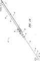
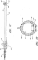
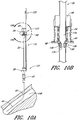
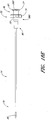
- FIGURE 1A illustrates an access device 20 that is configured to be inserted into a blood vessel (e.g., a vein or an artery). While the access device is described below in this context (i.e., for vascular access), the access device also can be used to access and place a medical article (e.g., catheter or sheath) into other locations within a patient's body (e.g., a drainage site) and for other purposes (e.g., for draining an abscess).
- a blood vessel e.g., a vein or an artery
- the present example of the access device is disclosed in the context of placing an exemplary single-piece, tubular medical article into a body space within a patient. Once placed, the tubular article can then be used to receive other medical articles (e.g., catheters, guidewires, etc.) to provide access into the body space and/or be used to provide a passage way for introducing fluids into the body space or removing (e.g., draining) fluids from the body space.
- the tubular medical article is a sheath or catheter that is configured primarily to provide a fluid passage into a vein.
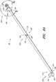
- FIGURES 1A and 1B illustrated an example of an access device 20.
- the access device 20 comprises a needle 22, a dilator 24, and a sheath 26.
- the access device also includes a guidewire section 28 and a track 30.
- the dilator 24 is preferably coaxially mounted on the needle 22, and the sheath 26 is coaxially mounted on the dilator 24.
- the telescoping nature of the access device's components can also be accomplished by arranging the components with their axes arranged substantially parallel rather than coaxially (e.g., a monorail-type design).
- each of these components includes a luminal fitting at a terminal end or transition (i.e., a hub) and elongated structure that extends from the fitting.
- the needle 22 includes a needle body 32 that extends distally from the needle hub 34
- the dilator 24 includes a dilator shaft 36 that extends distally from a dilator hub 38
- the sheath 26 includes a sheath body 40 that extends distally from a sheath hub 42.
- the guidewire section 28 comprises a guidewire 44 and preferably a guidewire hub or cap 46.
- the guidewire hub 46 is disposed on the proximal end of the guidewire 44; however, in other applications, the hub 46 can be disposed at a location between the ends of the guidewire 44.
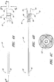
- FIGURES 2A-2G illustrate the needle body 32 and needle hub 34 of the needle 22, which are configured in accordance with an example of the access device, in isolation from the other components of the access device 20.
- the needle hub 34 is disposed on a proximal end of the needle body 32.
- the needle body 32 terminates at a distal end near a distal portion 50 of the needle 22, and the needle hub 34 lies at a proximal portion 52 of the needle 22.
- the needle body 32 preferably has an elongated tubular shape having a circular, constant-diameter inner bore and a circular, constant-diameter exterior surface. In other embodiments, however, the needle body 32 can have other bore and exterior shapes (such as, for example, but without limitation, an oval cross-sectional shape).
- the interior or exterior of the needle can also include grooves or channels. The grooves or channels may guide fluids within the needle bore either around or to certain structures of the needle 22 or within the needle 22 (e.g., around the guidewire). In some embodiments, the grooves or channels may assist in maintaining a desired orientation of the needle 22 with respect to the dilator.
- the needle body 32 has a sufficiently long length to access a targeted subcutaneous body space and has a sufficient gauge size to withstand the insertion forces when accessing the body space without causing undue trauma.
- the needle body can have a length between 3- 20 cm, and more preferably between 3-10 cm.
- the needle body 32 preferably has a length of 7 cm or greater, and more preferably has a length of 9 cm or greater, and most preferably has a length of 9 to 10 cm.
- the size of the needle preferably is 18 gauge or smaller, and more preferably between 18-28 gauge, and most preferably between 18-26 gauge for micro-puncture applications (peripheral IVs).
- the length and gauge of the needle body 32 should be significantly shorter and smaller, for example preferably between 3-4 cm and between 26-28 gauge.
- the needle body 32 includes at least one fenestration or opening 56 near a distal end of the needle body 32.
- the fenestration 56 extends through the wall of the needle body 32 and can have a variety of shapes and orientations on the needle body 32, as described in detail below.
- the needle body 32 can have a bevel tip 54 disposed on the distal portion 50.
- a fin 58 is preferably disposed at a circumferential location around the needle hub 34 that is aligned with the circumferential locations of the bevel on the needle tip and the opening or fenestration 56 in the needle. That is, the fin 58 is indexed with the bevel and fenestration.
- the physician or healthcare provider can determine the orientation of the beveled needle tip (and the fenestration 56) by noting the orientation of the exposed fin 58 even though the bevel is inside the vessel and the fenestration is covered by the sheath and/or dilator.
- an orientation of the fin 58 away from the patient coincides with a bevel up orientation of the needle tip within the vessel.
- the fenestration 56 is also on the same side as the fin 58, as seen in FIGURE 2C .
- the fin 58 also provides a grasping region to manipulate the needle hub 34.
- a physician or healthcare provider can place an index finger and thumb on the sides of the fin 58 to stabilize the needle hub 34, relative to the dilator 24 and/or sheath 26.
- the needle hub 34 slides relatively along the track 30 between a first position 121 and a second position 123 (example portions illustrated in FIGURE 6A ).
- the fin 58 can be held when performing the insertion step (which will be described below).
- the fin 58 can be used to stabilize the needle hub 34 while rotating the dilator hub 38.
- the fin 58 can be used by a physician or healthcare provider as an aid to grasp the access device 20 when the needle hub 34 is disposed at any position along the track 30.
- FIGURE 2D is an enlarged view of the side opening or fenestration 56 in the needle body 32.
- the one or more fenestration 56 provides a path through the side of the needle body 32.
- the fenestration 56 illustrated in FIGURE 2D has an oblong shape.
- the shape of the side opening 56 is not limited to the illustrated embodiment and may be round, oblong, square, or another shape.
- the needle hub 34 preferably includes locking structures at the proximal portion and distal portion of the needle hub 34. These locking structures may be a luer-thread-type or another type of connections.
- the locking structure on the proximal portion 52 of the needle hub 34 allows the physician or healthcare provider to secure another medical article to the proximal end of the needle hub 34.
- the needle hub 34 in the illustrated example includes an annular flange or lip 63.
- the lip 63 is threaded to allow the needle hub 34 to attach to other medical articles with a corresponding luer-nut locking feature.
- a physician or healthcare provider may attach a syringe or monitoring equipment to the locking structure on the proximal end to perform other procedures as desired.
- the needle hub 34 can also include a septum at its proximal end and/or a side port if these features are desirably for a particular application.
- the locking structure on the distal portion of the needle hub 34 allows the physician or healthcare provider, for example, to lock the needle hub 34 to the dilator hub 38 when the needle hub 34 is in the first position 121.
- the locking structure includes a latch element 66 on the needle hub 34.
- the latch element 66 releasably locks the needle hub 34 to the dilator hub 38.
- the locking structure allows the healthcare provider to advance the needle into a patient while grasping the needle hub 34, the dilator hub 38 or both.
- the guidewire 44 is introduced through a hollow portion 62 of the needle hub 34, through the needle body 32, and into a punctured vessel.
- the guidewire 44 allows the healthcare provider to guide the dilator 24 and sheath 26 into the vessel.
- the needle hub 34 may also comprise two tangs 68 that allow the needle hub 34 to slide along the track 30 between a first position 121 and a second position 123. While in the preferred embodiment the two tangs 68 of the needle hub 34 are engaged with the track 30 between the first position 121 and the second position 123, in other examples the needle hub 34 is only engaged with the track 30 over a portion of the length of the track 30 between the first position 121 and the second position 123.
- the sliding interconnection between the track 30 and the needle hub 34 also can be accomplished using other cooperating structures (e.g., a corresponding pin and tail of dovetail connection).
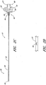
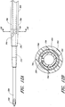
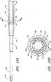
- FIGURE 3A is a plan view of the dilator 24 of the example depicted in FIGURE 1A .
- Figure 3B is a cross-sectional view of the dilator 24 of the example depicted in Figure 3A , taken along line 3B-3B.
- the illustrated dilator 24 comprises a dilator shaft 36, a dilator hub 38, a distal region 70, and a proximal region 72.
- the dilator shaft 36 includes a side openings or fenestrations 74; however, in other examples, the dilator shaft 36 can include fewer or greater numbers of fenestrations 74.
- the dilator shaft 36 may not include a fenestration 74 where a blood flash chamber(s) is disposed within the dilator (as will be described in more detail below).
- the dilator hub 38 may comprise one or more vents.
- the vents in the dilator hub 38 are formed by grooves 75.
- the dilator shaft 36 may comprise one or more longitudinal channels formed in the outer surface of the dilator shaft 36.
- the channel is an open channel.
- the side walls of the open channel are formed by ridges 76.
- the ridges 76 define generally smooth, arcuate exterior surfaces that interface with the sheath 26; however, in other embodiments, the ridges can have other shapes (e.g., can define more pronounced apexes).
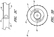
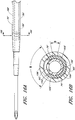
- FIGURE 3C is an enlarged plan view of a portion of the example illustrated in Figure 3A .
- the illustrated dilator shaft 36 comprises one or more side openings 74 and one or more channels formed between ridges 76.
- the side opening or fenestration 74 provides a fluid path through the side of the dilator shaft 36.
- the shape of the side opening 74 is not limited to the illustrated embodiment and may be round, oblong, square, or have another shape.
- the opening or fenestration 74 illustrated in FIGURE 3C has an oblong shape.
- the opening 74 in the dilator shaft 36 has an oblong shape with its major axis being non-parallel relative to the major axis of the oblong opening 56 in the needle 22.
- the needle opening 56 may extend in a longitudinal direction and the dilator opening 74 may extend in a circumferential direction or vice versa.
- the long axis of the dilator opening 74 is disposed generally perpendicular to the long axis of the needle opening 56.
- these openings 56, 76 can have other shapes, sizes and orientations that preferably obtain a significant degree of overlap to account for manufacturing tolerances and rotational misalignments.
- one of the fenestrations has a greater dimension in at least one direction than the other one of the fenestrations in the same direction. Accordingly, in the illustrated example, the needle fenestration 56 has a longer longitudinal dimension than the longitudinal dimension of the dilator fenestration 74.
- the channel formed between the ridges 76 extends in a proximal direction from a point distal to the opening 74.
- the ridges 76 in the illustrated example are disposed along the dilator shaft 36 and on opposite sides of the dilator shaft 36 so as to balance the dilator shaft 36 within the sheath.
- the ridges 76 form two channels there between. Balancing the dilator within the sheath allows the dilator to apply equal pressure to the inside circumference of the sheath.
- the dilator hub 38 may include locking structures at the proximal region 72 and the distal region of the dilator 24. Each locking structure may be a luer type or other type of connection.
- the dilator hub 38 comprises a first luer connection 78, a second luer connection 80, a lip 77, and a base 79.
- the first luer connection 78 engages to the needle hub 34 on the needle 22 illustrated in FIGURE 2E .
- the second luer connection 80 is disposed distal to the first luer connection 78.
- the second luer connection 80 (e.g., a male luer slip connector) can be configured to engage to the sheath hub 42 (e.g., a female luer slip connector) on the sheath 26 illustrated in FIGURE 1A . Additionally, the male-female lure slip connectors on these components can be reversed.
- FIGURE 3D is an enlarged proximal end view of the dilator 24 of FIGURE 3A .
- the dilator hub 38 comprises an opening 82 that releasably engages the latch element 66 on the needle hub 34 illustrated in FIGURE 2E-2F to secure the dilator hub 38 to the needle hub 34 when the needle hub 34 is in the first position 121.
- the male-female lure slip connectors on the dilator hub and the needle hub 34 can also be reversed in other examples.
- the color of the dilator 24 may be selected to enhance the contrast between the blood or other fluid and the dilator 24.
- blood flash for example, blood is observed flowing between the dilator 24 and the sheath to confirm proper placement of the needle in a blood vessel.
- the sheath is preferably manufactured from a clear or transparent material with the dilator 24 having a color that contrasts with the color of the fluid.
- the dilator 24 may have a white color to enhance its contrast with red blood. Other colors of dilator 24 could be employed depending on the color of the fluid and the degree of contrast desired.
- the dilator 24 may be manufactured of a clear or transparent material similar to the sheath to allow the physician to observe the blood flash through both the sheath and dilator 24.
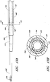
- FIGURE 3E is an enlarged perspective view of another example of a dilator hub 38A.
- the dilator hub 38A is similar to the dilator hub 38 illustrated in FIGURE 3A except that the dilator hub 38A further includes a spin nut or collar 84.
- the proximal end of the spin nut 84 rotates about an annular groove 73 in the dilator hub 38 (see FIGURE 3A ). Once disposed within the annular groove 73, the spin nut 84 is inhibited from moving in the distal direction but is free to rotate about the dilator hub 38A.
- the spin nut 84 can have an interengaging element that locks to a corresponding interengaging element on the sheath 26.
- the spin nut 84 includes an internal thread which engages with an external thread on the sheath hub 42 on the sheath 26 illustrated in FIGURE 1A .
- the dilator 24 or sheath 26 may separately, or together, form one or more passages to allow air or gas to escape or vent from between the dilator 24 and sheath 26 and/or between the needle and the dilator.
- the one or more passages may further be sized to inhibit the flow of a liquid, such as blood, while allowing air to pass therethrough.
- the one or more passages may be in the wall of the sheath 26, the sheath hub, the dilator hub 38, an exposed section of the dilator shaft, and/or formed between adjacent surfaces of the dilator 24 and sheath 26.
- FIGURE 3A shows longitudinally arranged grooves 75 that are formed between adjacent surfaces of the dilator 24 and sheath 26.
- Such venting passages can also be labyrinth.
- the adjacent surfaces form a luer slip connection between the sheath 26 and dilator 24.
- FIGURE 3F is a cross-sectional view taken along lines 3F-3F in FIGURE 3A and shows the grooves 75 equally spaced, though not required to be equally spaced, about the circumference of the luer slip surface.
- the grooves 75 are sized to allow air to escape from between the dilator and the medical article, such as a sheath, when the blood flash occurs.
- the one or more passages need not be in the form of a surface groove 75 and instead may be in the form of an opening or passageway.
- the one or more passages allow air to pass through the luer connection between the sheath and dilator hubs.
- a distal end of the passage 75 is located on the distal side of the luer connection with the proximal end of the passage 75 being located on the proximal side of the luer connection.
- the one or more passages may be sized to filter blood or other liquid or may include a filter or other structure that inhibits the passage of a liquid while allowing the passage of air.
- the sheath itself may include one or more passages in the form of small openings, pores or porous material.
- the one or more small openings, pores or porous material in the sheath can form a porous vent that allows air to pass yet retain blood.
- an extrusion process is used to create a long tubular body having one or more longitudinal grooves or channels on its outer diameter (OD) or within the substance of the dilator.
- the long tubular body exceeds the required length of a single dilator and preferably has a length that is many times greater than the length of a single dilator.
- a manufacturing die is employed in the extrusion process having geometry that reflects the desired geometry for the inside and outside diameters of the dilator and the thickness and circumferential span of the longitudinal grooves or channels or interior channels.
- the long tubular body includes two longitudinal OD channels on opposite sides of the body to enhance the balance of the dilator within the sheath.
- a single channel can provide a visible indicator for the blood flash.
- the two channels preferably extend along the length of the extruded tubular body.
- the illustrated example includes one or more channel disposed between the dilator and the sheath, one or more channels can in addition or in the alternative be formed between the needle and the dilator, within the dilator, and/or within the sheath.
- the dilator 24 thus is made partially or completely from clear, translucent, transparent, or semi-opaque material to visualize the fluid flash within the channel.
- the extruded tubular body is cut to the appropriate length for a single dilator.
- the two OD grooves extend for the entire length of the cut dilator.
- a tipping process is then employed on an end of the cut dilator to reform the tip.
- An end of the cut dilator is forced into a die/mandrel having geometry that matches the desired geometry of the tip of the finished dilator.
- the desired geometry is selected depending on, for example, the inside diameter of the sheath. It is desirable for the sheath and dilator to form a close fit or seal near the tip to promote blood flow in the proximal direction up the channel formed between the grooved dilator and sheath.
- the OD of the dilator in the tip region tapers in the distal direction.
- thermal energy is applied to the tip to reform the tip to match the die/mandrel.
- the thermal energy may be applied by any known technique, including using radiant heating from an infrared or RF heat source.
- the dilator in the tip region is reformed so that the grooves are essentially removed. With the grooves removed, the dilator is able to form the close fit or seal with the sheath near the tip.
- the grooves are maintained along the remainder of the dilator on the proximal side of the location where the tip of the sheath 26 sits on the dilator. After removal from the die/mandrel, the tip end of the dilator may be cleaned and cut as necessary to remove any manufacturing remnants.
- the one or more fenestrations in the dilator is cut through the dilator near the tip region and in or near the groove.
- Each fenestration may be cut by any known means, including a drill or laser. Further, the cutting device may be moved with respect to the dilator or vice versa to achieve an oblong or other shape for the fenestration.
- the end of the dilator opposite from the tip end can be flared to facilitate over molding the dilator hub onto the dilator.
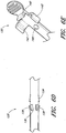
- FIGURE 4A is a plan view of the sheath 26 of the example depicted in FIGURE 1A .
- Figure 4B is a cross-sectional view of the sheath 26 of the embodiment depicted in Figure 4A , taken along line 4B-4B.
- FIGURE 4C is an enlarged proximal end view of the sheath 26 of FIGURE 4A .
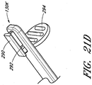
- Figure 4D is an enlarged perspective view of the sheath hub 42 of the sheath 26 of FIGURE 4A .
- the sheath 26 may comprise a sheath body 40, a sheath hub 42, a distal portion 90, and a proximal region 92.
- the sheath body 40 may be made partially or completely from clear, translucent, transparent, or semi-opaque material.
- the sheath body 40 can also include one or more radio opaque markers, such as, for example, barium sulfate stripes.
- the sheath includes two such radio opaque stripes disposed on diametrically opposite sides of the body 40.
- the sheath body 40 may be a single piece sheath through which a catheter or other medical article (e.g., a guidewire) is inserted into the vessel.
- the sheath body 40 forms a conduit for insertion of the catheter or other medical article (e.g., a guidewire).
- the sheath or a portion of the sheath can form a lumen that is in addition to the lumen(s) of the catheter.
- an equivalent to a triple lumen catheter can be formed by inserting a dual lumen catheter through the sheath body 40 with the sheath body 40 itself forming a third lumen.
- a peel-away sheath can include perforations, serrations, skives, or other structures, or include other materials (e.g., PTFE with bismuth) to allow the physician or healthcare provider to remove easily a portion or the entire sheath body 40.
- the sheath hub 42 may include a luer slip connection and a lock member 94.
- the locking member 94 may comprise a locking or attaching structure that mates or engages with a corresponding structure.
- the lock member 94 can be a luer connection 94 which can be configured to engage with the second luer connection 80 of the dilator hub 38.
- the sheath hub 42 preferably is designed so that the locking mechanism or second luer connection 80 of the dilator hub 38 can enter the sheath hub 42 substantially unobstructed.
- the physician or healthcare provider can push, pull, or twist the sheath hub 42 and possibly disengage or engage the locking member 94 with a corresponding connector on another medical article.
- the locking member 94 can be, for example, a luer connection, a protruding bump, dent, etc., that creates a mechanical fit so that the dilator hub 38 and the sheath hub 42 are releasably interlocked.
- the locking member 94 of the sheath hub 42 comprises a luer connection.
- the sheath hub 42 preferably engages with the corresponding second luer connection 80 on the dilator hub 38.
- the locked position can be disengaged or engaged by pulling, squeezing, pushing or twisting the dilator hub 38 relative to the sheath hub 42.
- the sheath hub 42 can comprise a lip 95.
- the lip 95 can be threaded to allow the sheath hub 42 to attach to other medical articles with a corresponding locking feature.
- the sheath hub 42 preferably comprises one or more surface features to allow the physician or healthcare provider to easily grasp or manipulate the sheath 26 and/or access device 20.
- the sheath hub 42 includes a squared grip 96 and ridges 98.
- the sheath hub 42 may comprise radially extending wings or handle structures to allow for easy release and removal of the sheath body 40 from other parts of the access device 20.
- the wings are sized to provide the healthcare provider with leverage for breaking apart the sheath hub 42.
- the sheath hub 42 may comprise a thin membrane connecting the halves of the sheath hub 42. The membrane is sized to keep the halves of the sheath hub 42 together until the healthcare provider decides to remove the sheath hub 42 from the access device. The healthcare provider manipulates the wings to break the membrane and separate the sheath hub 42 into removable halves.
- FIGURE 5A is a perspective view of the guidewire section 28 of the example depicted in FIGURE 1A .
- FIGURE 5B is a plan view of the guidewire section 28 depicted in FIGURE 5A , which preferably includes the guidewire hub 46.
- the guidewire hub 46 can comprise one or more surface features to allow the physician or healthcare provider to easily grasp or manipulate the guidewire hub 46 and/or access device 20.
- the guidewire hub 46 comprises one or more ridges 110.
- the outer surface of the guidewire hub 46 engages with a locking mechanism 130 on the track 30 when the guidewire hub 46 is in a third position 125 (example third position illustrated in FIGURE 6A ).
- the guidewire 44 may form a close fit with the inside diameter of the needle body so as to provide a self-aspirating function when retracted.
- an outside diameter of the guidewire 44 may be selected to form a close fit with the needle along the length of the guide wire or along only a portion of the guidewire 44.
- the distal end portion of the guidewire can have a reduced diameter in comparison to other sections of the guidewire.
- the size of such reduced diameter section can be selected to permit fluid to pass to the fenestration 56 in the needle body even when the guidewire has been advanced beyond the distal tip of the needle.
- FIGURE 6A is a perspective view of the track 30 of the example depicted in FIGURE 1A .
- Figure 6B is a plan view of the track 30 illustrated in FIGURE 6A .
- FIGURE 6C is a side view of the track 30 illustrated in FIGURE 6A .
- the track 30 in the illustrated example comprises a distal portion 120, a proximal portion 122, a distal locking member 124 that connects the track to the dilator hub 38, a locking mechanism 128 that inhibits further proximal and distal movement of the needle hub 34 once the needle hub 34 is slid from the first position 121 to the second position 123 along the track 30, and a locking mechanism 130 that allows the guidewire hub 46 to attach to the track 30 when the guidewire hub is in the pre-loaded state or third position 125.
- the track is made of polycarbonate material; however, as explained below, other materials can be used.
- the track 30 may further include a track section 132 of reduced width as shown most clearly in FIGURES 6A and 6B .
- the reduced width facilitates assembly of the needle hub to the track 30.
- the illustrated example includes a rib 133 on the distal portion 120 of the track 30.
- the rib 133 provides additional structural reinforcement between the distal locking member 124 and the remainder of the track 30.
- the distal locking member 124 connects to the dilator 24 and allows the track 30 to extend proximally from the dilator 24.
- the locking member 124 can comprise two curved arms 124 that connect to the dilator hub 38 between the dilator hub lip 77 and the dilator hub base 79. The locking member 124 limits movement of the track 30 in a distal or proximal direction relative to the dilator hub 38 but allows the track 30 to rotate freely around the dilator hub 38.
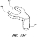
- FIGURE 6D is an enlarged view of a portion of the example depicted in FIGURE 6B .
- the locking mechanism 128 is formed by varying the width of the track in the region of the second position 123.
- the illustrated example includes a track section 134 of increasing width in the distal direction, a track section 136 of reduced width distal to the track section 134 of increasing width, and two finger elements 138.
- the two finger elements 138 project from the distal end of the track section 136 toward the proximal end of the track 30 and flare away from the longitudinal axis of the track 30.
- FIGURE 6E is an enlarged view of a portion of the example depicted in FIGURE 6B .
- the locking mechanism 130 is formed by a clip, clasp or other structure that engages with a portion of the guidewire hub or with a portion of the track 30 when the guidewire hub is in the third position. Some or all of the engagement structure may be part of the track 30, be part of the guidewire hub, or be split between the track 30 and guidewire hub. In the illustrated embodiment, the locking mechanism 130 extends from the track 30 and engages with the guidewire hub.
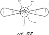
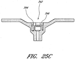
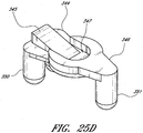
- the locking mechanism 130 comprises a rectangular element 140 protruding from the track 30, two track arms 142 projecting from the track 30 distal to the rectangular element 140, and a stop 144 protruding from the track 30 distal to the track arms 142.
- the locking mechanism between the needle hub and the dilator resides on the proximal side of the dilator hub.
- the locking mechanism can be disposed at other locations as well.
- the locking mechanism includes two pivotal levers which are joined by a locking hinge
- the locking mechanism can be disposed radially relative to the needle hub.
- one lever is pivotally coupled to the dilator and the other lever is pivotally coupled to the needle.
- an elongated structure can extend parallel to the needle body from the needle hub within the dilator. Once the needle hub is moved a sufficient distance away from the dilator, additional structure of the locking mechanism (e.g., a detent) engages the elongated structure to inhibit further movement of the needle relative to the dilator. Accordingly, as illustrated by these additional examples, the locking mechanism operating between the needle and the dilator can be disposed at a variety of locations relative to the dilator hub.
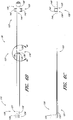
- FIGURE 7A is an enlarged plan view of the access device of the example depicted in FIGURE 1A pre-loaded with the guidewire.
- FIGURE 7B is a side view of the example depicted in FIGURE 7A .
- FIGURE 7C is a cross-sectional view of the example depicted in FIGURE 7A along line 7C-7C.
- FIGURE 7D is a proximal end view of the access device 20 of FIGURE 7A .
- the guidewire hub 46 is locked to the track 30 when the guidewire hub 46 is located in a third position 125. In this position, the guidewire hub 46 can be secured to the track 30 between the rectangular element 140 and the stop 144.
- the guidewire hub 46 can releasably lock between the rectangular element 140 and the stop 144.
- the track arms 142 can further secure the guidewire hub 46 to the track 30.
- This locking mechanism can arrest unintended rotational and axial movement of the guidewire 44 at least in the distal direction when the guidewire hub 46 is in the third position 125.
- the healthcare provider may disengage the guidewire hub 46 from the track 30 to allow distal movement of the guidewire through the access device 20.
- the needle hub 34 is locked to the dilator hub 38 when the needle hub 34 is in the first position 121.
- the openings or fenestrations in the needle and dilator are in register or in alignment with each other.
- the needle 22 and the dilator 24 are inhibited from at least unintentional rotational and axial movement relative to each other.
- the fenestrations or openings maintain their general alignment.
- the dilator hub 38 In the pre-loaded state, the dilator hub 38 is secured to the sheath hub 42. This can inhibit at least unintentional rotational and axial movement between the dilator 24 and the sheath 26. In embodiments where the sheath hub 42 and the dilator 24 have only a luer slip connection, the dilator 24 and sheath hub 42 may rotate relative to each other.
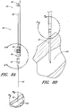
- FIGURE 8A is a plan view of the example depicted in FIGURE 1A that illustrates an operational step of one method of using the access device 20.
- FIGURE 8A depicts the needle body 32 of the access device 20 inserted into a vessel 148, such as a vein. While the described method refers to vascular access, the access device 20 also can be used to access and place a catheter or sheath into other locations within a patient's body (e.g., for draining an abscess) and for other purposes.
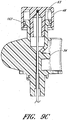
- FIGURE 8B is an enlarged plan view of the portion of the example illustrated in FIGURE 8A which is circled by line 8B-8B.
- FIGURE 8C is an enlarged plan view of the portion of the embodiment illustrated in FIGURE 8B which is circled by line 8C-8C.
- FIGURE 8D is an enlarged cross-sectional view of the example depicted in FIGURE 8C along line 8D-8D.
- the needle body 32 comprises one or more side openings 56 in its side wall.
- the dilator shaft 36 comprises one or more side openings 74.
- the side openings 56, 74 may have the same or different shapes as well as aspect ratios.
- the side opening 56 in the needle body 32 has a different aspect ratio than the side opening 74 in the dilator shaft 36.
- the side opening 56 in the needle body 32 is elongated in one direction (e.g., substantially parallel to the longitudinal axis of the needle body 32).
- the side opening 74 in the dilator shaft 36 is elongated in a different direction (e.g., along the circumference of the dilator shaft 36).
- FIGURES 8A-D illustrate the alignment between only one set of corresponding side openings. Other sets of side openings can also be aligned or be misaligned depending upon the relative orientations of the needle body 32 and the dilator shaft 36.
- the dilator shaft 36 is coaxially positioned to minimize an annular space 150 between the needle body 32 and the dilator shaft 36.
- the inner surface 152 of the dilator shaft 36 need not, though it can, lie directly against the outer-surface 154 of the needle body 32.
- the annular space 150 between the outer-surface 154 of the needle body 32 and the inner surface 152 of the dilator shaft 36 is minimized to inhibit the flow of blood or its constituents (or other bodily fluids) into the annular space 150 between the dilator shaft 36 and needle body 32.
- this feature minimizes the blood's exposure to multiple external surfaces and reduces the risk of contamination, infection, and clotting.
- the dilator shaft 36 is coaxially mounted to the needle body 32 such that at least part of one side opening 56 disposed on the needle body 32 is rotationally aligned with at least part of one side opening 74 on the dilator shaft 36.
- the needle body 32 and dilator shaft 36 maintain rotational alignment so that blood flows through the needle side opening 56 and dilator side opening 74.
- the sheath body 40 is preferably made partially or completely from clear, semi-opaque, translucent, or transparent material so that when blood flows into the needle body 32, (1) through the needle side opening 56, (2) through the dilator side opening 74, and (3) into a channel 156, the physician or healthcare provider can see the blood.
- the channel 156 is formed between the dilator shaft 36 and the sheath body 40 and defined by one or more ridges 76 on the dilator shaft 36.
- the channel 156 is formed within a wall of the dilator shaft 36 with the dilator shaft 36 preferably comprising a transparent material. Blood will indicate to the physician or healthcare provider that the bevel tip 54 of the needle body 32 has punctured a vessel 148.
- the needle body 32 and dilator shaft 36 may (both) have multiple side openings where some or all of these side openings can be rotationally aligned.
- the channel 156 can have an axial length that is almost coextensive with the length of the sheath 26. In other embodiments, the channel 156 can be significantly smaller than the elongated channel 156 just described. For example, but without limitation, the channel 156 can be disposed within a distal, mid and/or proximal portion(s) of the sheath 26. The channel 156 alternatively can have a linear, curved or spiral shape along an axial length of the sheath 26 or can be formed by a plurality of such shapes. The channel 156 may have various thicknesses and span angles. The thickness of the channel 156 can range from almost close to zero to 0,254 mm (0,010 inches).
- the channel 156 has a thickness of about 0,0127 mm to about 0,0762 mm (0,0005 to about 0,003 inches). More preferably, the channel 156 can have a thickness of about 0,0254 to about 0,0508 mm (0,001 inches to about 0,002 inches).
- the channel 156 can have a span angle ⁇ about the axis of the dilator 24 of about 30 degrees to about 210 degrees or more, but preferably less than 360 degrees. More preferably, the channel 156 can have a span angle ⁇ of about 60 to 150. In the illustrated embodiment, the channel 156 spans 120 degrees.
- the thickness and span angle ⁇ can be chosen so as to optimize the capillary action that occurs within the channel 156 as fluid (e.g., whole blood) enters the channel 156 as may further be selected based on the expected pressure in the body cavity and viscosity of the liquid.
- fluid e.g., whole blood
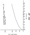
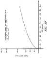
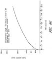
- FIGURES 8E-8G are graphs of test data illustrating how quickly a fluid is drawn up the surfaces of the channel 156 when the span angle is 120 degrees, the contact angle ( ⁇ ) is 5 degrees, and the circumferential length (H) is 0.64mm at 60 degrees.
- the filling length (mm) is plotted on the y-axis
- time (seconds) is plotted on the x-axis. The tests were performed at hydrodynamic pressures similar to pressures experienced in peripheral vessels.
- FIGURE 8E illustrates the rate fluid is drawn up a channel 156 with a gap height width of 0,0508 mm (0,002 inches)
- FIGURE 8F illustrates the rate fluid is drawn up a channel 156 with a gap height width of 0,0254 mm (0,001 inches)
- FIGURE 8G illustrates the rate fluid is drawn up a channel 156 with a gap height width of 0,0127 mm (0,0005 inches).
- fluid is drawn up the fastest in a channel with a gap height width of 0,0127 mm (0,0005 inches) followed by a channel with a gap height width of 0,0254 mm (0,001 inches), followed by a channel with a gap height width of 0,0508 mm (0,002 inches).
- the shape of the channel 156 described above and the resulting capillary action was optimized for use with whole blood as opposed to other fluids having a different viscosity than whole blood (e.g. leukocytes, pus, urine, plasma).
- the shape of the channel 156 is not limited to the disclosed shape and may be optimized for draining other liquids, such as pus.
- the shape of the channel 156 described above was optimized for peripherally located vessels where the pressure in the vessel enhances the capillary action and resulting blood flash as well as for vessels located in the regions where the pressure may be low. For example, in the thorax region of the body, the expected pressure in the veins may be lower than in a peripherally located vein when the patient breathes.
- a different size of the channel for use of the access device 20 in other regions of the body may be employed taking into account the expected pressure within the vessel or body cavity.
- an outer-surface 160 of the dilator shaft 36 and/or an inner surface 158 of the sheath body 40 can be coated with a substance to promote or enhance the capillary action within the channel 156.
- a hydrophilic substance can be used to coat outer-surface 160 of the dilator shaft 36 and/or the inner surface 158 of the sheath body 40 to enhance capillary action.
- a surfactant can be used to coat the outer-surface 160 of the dilator shaft 36 and the inner surface 158 of the sheath body 40.
- a surfactant that can be used is Lutrol 68TM, commercially available from BASFTM; other surfactants can also be used.
- Other surfaces that can be coated include the inner surface of the needle body 32, the outer surface 154 of the needle body 32, the inner surface 152 of the dilator shaft 36, and the guidewire 44. These surfaces, including the outer-surface 160 of the dilator shaft 36 and the inner surface 158 of the sheath body 40, can be coated with a surfactant individually, or in combination. In the examples described above it may be preferable to coat both the outer-surface 160 of the dilator shaft 36 and the inner surface 158 of the sheath body 40 to promote or enhance progression of a body fluid through the channel 156. However, in some examples it may be preferable to only coat one of these two surfaces with a surfactant.
- a surfactant can accelerate and facilitate the progression of blood through the needle, dilator, or sheath. Accordingly, smaller needles, dilators, and sheaths can be used while still allowing blood to travel through said pieces with sufficient speed to indicate to an operator that the needle has entered the vessel or drainage site. Notably, in most examples a body fluid will pass through the needle, and thus in most examples it can be desirable to apply a surfactant to the interior surface of the needle.
- one or more of these components can be made of a hydrophilic material.
- a hydrophilic substance additionally can be applied to the outer surface of the sheath 26 to act as a lubricant to ease insertion of the sheath 26 into a patient.
- Other lubricants or lubricous coatings can be used on the exterior of the sheath 26 or at least the outer surface of the sheath can be formed of a lubricous material.
- the sheath 26 can be coated or formed with agents (e.g., heparin), which elute from the sheath, to facilitate the clinical application of the access device 20.
- the outer surface of the sheath 26 can include a coating of silicone, such as Dow Corning 360 Medical Fluid, 12,5000 CSTTM, commercially available from Dow Coming.
- the sheath can be coated with a surfactant in some embodiments.
- FIGURE 8H is a cross sectional view of the example depicted in FIGURE 8C along line 8H-8H.
- the sheath body 40 is coaxially positioned to minimize the annular space 157 between the sheath body 40 and the dilator shaft 36 while still allowing relative movement of the sheath body 40 and the dilator shaft 36.
- the inner surface 158 of the sheath body 40 need not, though it can, lie directly against the outer-surface 160 of the dilator shaft 36.
- the annular interface 157 between the outer-surface 160 of the dilator shaft 36 and the inner surface 158 of the sheath body 40 may be reduced in this region to inhibit the distal flow of blood or its constituents (or other bodily fluids) from the opening 74 in the dilator shaft 36.
- FIGURE 8I is an enlarged plan view of the portion of the example illustrated in FIGURE 8A which is circled by line 8I-8I.
- FIGURE 8J is a cross-sectional view of the embodiment depicted in FIGURE 8I.
- FIGURES 8I and 8J illustrate the needle hub 34 locked to the dilator hub 38 when the needle hub is in the first position 121.
- the dilator shaft 36 may be coaxially mounted to the needle body 32 by slipping a hollow section 84 of the dilator shaft 36 over the needle body 32 and releasably securing the dilator hub 38 to the needle hub 34.
- the proximal end 86 of the dilator hub 38 is configured to mechanically fit and interlock with the needle hub 34.
- the dilator shaft 36 may be releasably mounted to the needle body 32 so that the dilator shaft 36 can be mounted and released, or vice versa, from a coaxial position relative to the needle body 32.
- This locking mechanism can inhibit at least some unintentional rotational and axial movement between the needle 22 and the dilator 24 when the needle hub 34 is in the first position.
- the needle hub 34 may have a luer connection 64 that locks to the luer connection 78 of the dilator hub 38.
- the needle hub 34 may also have latch element 66 that locks to the opening 82 in the dilator hub 38.
- FIGURES 8I and 8J illustrate the dilator hub 38 engaged with the sheath hub 42 when the access device 20 is inserted into a vessel 148.
- the proximal end 86 of the sheath hub 42 is configured to mechanically fit and releasably engaged with the dilator hub 38.
- the luer connection 80 in the dilator hub 38 can engage with the lock member 94 of the sheath hub. The resulting friction fit can inhibit at least some unintentional rotational and axial movement between the dilator 24 and the sheath 26 when the access device 20 is inserted into a vessel 148.
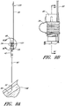
- FIGURE 9A is a side view of the embodiment depicted in FIGURE 1A that illustrates a further operational step of the access device 20.
- FIGURE 9A depicts the guidewire 44 of the access device 20 advanced in a distal direction into a vessel 148. This can be achieved by advancing guidewire hub 46 from the third position 125 in a distal direction. The guidewire hub 46 is then locked to the needle hub 34 when the needle hub 34 is in the first position 121.
- FIGURE 9B is an enlarged side view of the portion of the example illustrated in FIGURE 9A which is circled by line 9B-9B.
- FIGURE 9C is a cross-sectional view of the embodiment depicted in FIGURE 9B .
- FIGURE 9C illustrates the locking mechanism between the guidewire hub 46 and the needle hub 34.
- the guidewire hub 46 is configured to mechanically fit and releasably or irreversibly interlock with the needle hub 34.
- the guidewire hub 46 includes a nub 162 on the inner surface of the guidewire hub 46.
- the nub 162 of the guidewire hub can lock onto the needle hub 34 by advancing the guidewire hub 46 in a distal direction until the nub 162 is secured within the threaded groove on the lip of the needle hub 46.
- the guidewire hub 46 can lock to the needle hub 34 via corresponding threaded elements.
- FIGURE 10A is a side view of the example depicted in FIGURE 1A that illustrates another operational step of the access device 20.
- FIGURE 10A depicts the dilator shaft 36 and the sheath body 40 advanced in a distal direction into a vessel 148. This can be achieved by releasing the dilator hub 38 from the needle hub 34 and advancing the dilator 24 and sheath 26 in a distal direction relative to the needle hub 34 along the guidewire and needle.
- FIGURE 10A further illustrates the proximal movement of the needle 22 and guidewire section 28 relative to the dilator 24 and the sheath 26.
- the needle hub 34 will lock to the track 30 when the needle hub 36 reaches the second position 123.
- FIGURE 10B is an enlarged rear view of the portion of the example illustrated in FIGURE 10A which is circled by line 10B-10B.
- the needle hub 34 locks onto the track 30 via the locking mechanism 128 in the second position 123.
- the needle hub tangs 68 slide in a proximal direction over the track fingers 138 and the tangs 68 can lock into place between the track fingers 138 and the track section of increasing width 134. This arrests and, more preferably, substantially irreversibly prevent axial movement of the needle body 32 at least in the distal direction when the needle hub 34 is in the second position 123.
- the locking mechanism 128 irreversibly prevents the needle hub 34 from moving in either the proximal or distal directions once engaged. Furthermore, the distal tip 54 of the needle 22 is drawn into the dilator 24 to sheath the distal tip 54 when the needle hub 34 is in the second position 123. Thus, this locking mechanism 128 inhibits the bevel tip 54 disposed on the distal portion 50 of the needle body 32 from being advanced beyond the distal end of the dilator shaft 36 once the dilator shaft 36 has been advanced over the needle body 32 during use. The dilator shaft 36 thus sheaths the sharp bevel tip 54 of the needle body 32 to inhibit accidental needle sticks from occurring.
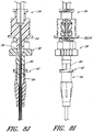
- FIGURE 11A is a side view of the example depicted in FIGURE 1A that illustrates the final operational step of the access device 20.
- FIGURE 11A illustrates the removal of the guidewire 44 and the dilator shaft 36 from the vessel leaving the sheath body 40 properly inserted within the vessel 148.
- FIGURE 11B is an enlarged plan view of the portion of the embodiment illustrated in FIGURE 11A which is circled by line 11B-11B. As clearly shown in FIGURE 11B , the distal end of the dilator shaft 36 and the guidewire 44 extend beyond the sharp bevel tip 54 of the needle body 32 to inhibit accidental needle sticks from occurring.
- openings 56, 74 in the needle body 32 and dilator shaft 36 with different aspect ratios will increase the likelihood that the openings 56, 74 in the needle body 32 and dilator shaft 36 will be aligned so that blood flows substantially unobstructed through the needle side opening 56 and dilator side opening 74.
- FIGURE 12A is a plan view of another embodiment of the openings 56, 74 in the needle body 32 and dilator shaft 36 illustrated in FIGURES 8B and 8C .
- FIGURE 12B is an enlarged cross-sectional view of the embodiment depicted in FIGURE 12A along line 12B-12B.
- FIGURES 12A and 12B depict a needle body 32A with an oblong opening 56A and a dilator shaft 36A with a circular opening 74A.
- the needle can have a circular opening and the dilator can have an oblong opening.
- FIGURE 13A is a plan view of another example of the openings 56, 74 in the needle body 32 and dilator shaft 36 illustrated in FIGURES 8B and 8C .
- FIGURE 13B is an enlarged cross-sectional view of the example depicted in FIGURE 13A along line 13B-13B.
- FIGURES 13A and 13B depict a needle body 32B with a circular opening 56B and a dilator shaft 36B with a circular opening 74B that is larger than the circular opening 56B in the needle body 32B.
- the opening in the dilator can be smaller than the opening in the needle. These examples can also increase the likelihood that the openings 56B, 74B will be at least substantially aligned so that blood flows through the needle side opening 56B and dilator side opening 74B.
- the dilator shaft 36 may have one or more channels 156 formed between ridges 76 to form a conduit or flow path between the sheath body 40 and the dilator shaft 36 to enable the physician or health care provider to view the blood after the bevel tip 54 of the needle body 32 has properly punctured a vessel or the channels may be formed without ridges but by extruding axial indentations of various possible configurations or by forming fully enclosed channels within the dilator shaft or body.
- FIGURE 14A is a plan view of another example of the ridges 76 depicted in FIGURE 8C .
- FIGURE 14B is an enlarged cross-sectional view of another example of the ridges 76 depicted in FIGURE 8D .
- FIGURES 14A and 14B depict two ridges 76C on the inner surface 158C of the sheath body 40C that form at least one channel 156C between the sheath body 40C and the dilator shaft 36C.
- FIGURE 15A is a plan view of another example of the ridges 76 depicted in FIGURE 8C .
- FIGURE 15B is an enlarged cross-sectional view of another example of the ridges 76 depicted in FIGURE 8D .
- FIGURES 15A and 15B depict two ridges 76D on the inner surface 158D of the sheath body 40D and two ridges 76E on the outer surface 160D of the dilator shaft 36D that combine to form a channel 156D between the sheath body 40D and the dilator shaft 36D.
- the two ridges 76D on the inner surface 158D of the sheath body 40D can each be about 0.0005 inches thick and the two ridges 76E on the outer surface 160D of the dilator shaft 36D can each be about 0.0005 inches thick.
- FIGURE 16A is a plan view of another example of the ridges 76 depicted in FIGURE 8C .
- FIGURE 16B is an enlarged cross-sectional view of another example of the ridges 76 depicted in FIGURE 8D .
- FIGURES 16A and 16B depict many ridges on the outer surface 160E of the dilator shaft 36E. Between adjacent ridges are splines 76F. The splines 76F form a plurality of channels 156E between the sheath body 40E and the dilator shaft 36E. One or more of the channels 156E can have the same span angle or different span angles ⁇ . In the illustrated example the channels 156E have span angles of 120 degrees and 23 degrees. In another example, a single ridge 76 can spiral around the exterior of the dilator along its length.
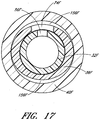
- FIGURE 17 is an enlarged cross-sectional view through another example of the access device and shows the channel 156F formed between a medical article or sheath body 40F and a dilator shaft 36F that have dissimilar shapes.
- the outer surface of the dilator shaft 36F has an oval shape while the inner surface of the sheath body 40F has a round shape.
- the oval dilator shaft 36F and the adjacent round sheath body 40F form one or more channels or gaps 156F between the sheath body 40F and the dilator shaft 36F.
- the shapes of the sheath body 40F and dilator shaft 36F are not limited to round and oval and may include any other combination of dissimilar shapes in adjacent regions of the sheath body 40F and dilator shaft 36F.
- the outer surface of the dilator shaft 36F is oblong and the inner surface of the sheath body or medical article 40F is round.
- the outer surface of the dilator shaft 36F is round and the inner surface of the medical article 40F is square.
- the gap or channel 156F can follow a longitudinal axis, a spiral path along the longitudinal axis, a linear path along the longitudinal axis or other path along the access device. In some modes, the linear path is parallel to the longitudinal axis.
- the gap or channel 156F thickness can vary along at least a portion of a length of the gap or channel 156F.
- the access device in another mode, includes a blood flash-back space defined between the shaft of the needle and the shaft of the dilator.
- the flash-back space preferably vents to the atmosphere and more preferably vents independent of the sheath.
- a vent passage is formed through the dilator, through the needle, or between the dilator and the needle.
- FIGURES 18A-18E illustrate an example of this mode of the access device, wherein a vent channel is formed between the needle and the dilator.
- the needle body 32G includes one or more fenestrations 56, and one or more ridges 176 (e.g., two ridges 176 are shown in the illustrated embodiment).
- the ridges 176 define the sides of at least one channel 256 extending along a length of the needle body 32G.
- additional channels 256 can be formed with additional ridges.
- channels 256 can be formed with a protruding ridge, or without a protruding ridge such as with a depression(s) or with a concentric gap.
- a channel 256 can be formed with protruding or non-protruding ridges on the inner surface of the dilator shaft 36G (instead of or in addition to features on the needle body 32G).
- the channel 256 is depicted as straight, it can also form other patterns such as a helix or another shape wrapping about the access device. Further, where multiple channels are present they can form intersecting helices, parallel helices, or other patterns.
- a distance between the needle body 32G and a dilator shaft 36G e.g. where the inner diameter of the dilator shaft exceeds the outer diameter of the needle body
- the needle hub 34G can include one or more venting grooves 175.
- the venting grooves 175 are on the luer connection 64, but in other examples they can be located on the needle body 32G, on the dilator shaft 36G, pass through the needle hub 34G, pass through a dilator hub 38G, or take some other path.
- the venting grooves 175 can provide communication between the channels 256 (or similar spaces) and the ambient atmosphere.
- the luer connection 64 can be configured to cooperate with the dilator hub 38G to form a substantially liquid tight seal, such that a substance can only escape through the venting grooves 175.
- a generally radially extending side 180 of the needle hub 34G can be configured to rest far enough apart from a corresponding face 200 of the dilator hub 38G to allow air to pass between them, from the venting grooves 175.
- venting grooves 175 can form a passage sufficiently small in cross-sectional area to allow the escape of gases (e.g., air) to the ambient atmosphere while hindering the escape to the ambient atmosphere of body liquids (e.g., red blood cells) with high molecular sizes, viscosities, or surface tensions. Further, in some embodiments multiple such passages can be provided, allowing adequate air ventilation despite small cross-sectional passages.
- gases e.g., air
- body liquids e.g., red blood cells
- multiple such passages can be provided, allowing adequate air ventilation despite small cross-sectional passages.
- the small cross-sectional area of the passage can be provided between two opposing surfaces of the dilator hub 38G and the needle hub 34G.
- at least a portion of the venting groove 175 on the needle hub 34G can be configured to receive a generally correspondingly shaped venting surface on the dilator hub 38G without entirely blocking the venting groove.
- the resulting passage between the surfaces of the needle hub 34G and the dilator hub 38G thus define at least a region of relatively small cross-sectional area to permit air flow but restrict the flow of bodily fluids.
- venting structure is depicted as grooves 175 in the illustrated example, other structures can perform similar functions.
- a single reduced space location between the needle body 32G and the dilator body 34G can permit the escape of air while inhibiting the flow of blood proximally beyond the reduced space location.
- a labyrinth passage can be disposed between the ambient atmosphere and the flash-back space (the space between the needle and dilator).
- one or more of the venting grooves 175 can be filled at least in part by a porous material that permits gases to flow through the material but inhibits the passage of a body fluid (e.g., blood).
- a porous material that permits gases to flow through the material but inhibits the passage of a body fluid (e.g., blood).
- a body fluid e.g., blood
- Such material can be integrally formed into the needle hub 34G or dilator hub 38G such that the material and the hubs are unitary.
- the material can then comprise any portion of the length of the venting grooves 175.
- the material can be placed into the venting grooves 175 or a receptacle in communication with the groove(s). When the material is placed into the groove 175, the groove can include a receiving portion such as a groove notch 185 configured to receive the porous material.
- vent passages in other examples can be entirely formed by such porous material.
- Suitable porous materials include, but are not limited to a porous polymer such as HDPE, UHMWPE, PP, PTFE, PVDF, EVA, PE, Nylon, and PU, of pore size approximately 2.5 microns.
- a combination of pore volume and pore size can be chosen to allow passage of gases (such as air) but inhibit the passage of body fluids (such as blood).
- venting passages can be tubes defined solely by either the needle hub 34G or the dilator hub 38G.
- the channel 256 can lead to an opening in the needle hub 34G.
- This opening can include any of the characteristics discussed above to control the passage of gases and fluids. The opening can thus allow the escape of gases (e.g. air) through the needle hub 34G to the ambient atmosphere while inhibiting the passage of body fluids (e.g. blood).
- a similar venting passage can be a tube defined solely by the dilator hub 38G. It will be clear from the disclosure herein that a variety of passages (e.g. venting grooves 175, tubes, porous material, etc.) can be used to allow the escape of gases (e.g. air) to the ambient atmosphere while inhibiting the escape of body fluids (e.g. blood).
- venting passages can be within the dilator shaft 36G and the sheath body 40.
- a venting hole or a patch of venting material can be provided in each of the dilator shaft 36G and the sheath body 40.
- these venting structures can overlap, allowing gases to pass directly from one to the other.
- these venting structures can be positioned some distance away from each other, in which case a channel or groove similar to those in FIGURE 18D can be provided between the dilator shaft 36G and the sheath body 40 to bring the venting structures into communication.
- These venting structures can be provided proximal from the fenestration 56 in the needle body 32G.
- the dilator shaft 36G in this example can have no fenestration and can be generally continuous.
- the dilator shaft 36G can thus radially close the channel 256 (or similar space).
- the same functionality can be accomplished with ridges in the dilator shaft 36G cooperating with an otherwise generally continuous needle 32G including a fenestration 56.
- the dilator shaft 36G can be formed of a translucent material in the entirety, or alternatively be translucent in at least the region adjacent the channel 256.
- the sheath body 40 can be similarly formed of a translucent material. In other examples, the material can be transparent instead of only translucent. In further embodiments, the material can be only partially translucent both spatially and temporally.
- the material of the dilator shaft 36G and/or the sheath body 40 can be translucent near the channel 256, allowing visual confirmation of e.g. blood flash-back.
- the visual characteristics of the material can change upon entry of a body fluid (e.g. due to temperature change or molecular interaction). The material can thus become translucent upon entry of a body fluid, or in other embodiments change color or provide some other visual indication.
- the access device depicted in FIGURES 18A-18E can include surfactants and/or lubricious coatings, as described above.
- a surfactant can be applied to the interior of the dilator shaft 36G, the exterior of the needle 32G, and/or the interior of the needle.
- the surfactant can be applied to any combination of these surfaces, depending on the desired effect.
- the surfactant can be applied solely to the outer surface of the needle, solely to the inner surface of the dilator, or solely to the inner surface of the needle.
- a surfactant can be applied to combinations of these surfaces, such as to both the inner surface of the dilator and the outer surface of the needle.
- the surfactant can ease the passage of a body fluid through spaces within the access device, accelerating flashback.
- a similar channel can be provided between a dilator shaft and a sheath body, and the surfactant can be supplied on the inner surface of the sheath and the outer surface of the dilator.
- channels can be provided both between the dilator and needle and the dilator and sheath, with the channels being in communication via a fenestration in the dilator, as described herein.
- the outer surface of the sheath can be coated with a surfactant, lubricious material, or the like.
- the channel 156 can be formed by having one complete ridge on the inner surface of the sheath and one complete ridge on the outer surface of the dilator.
- the inner surface of the sheath can have two ridges that run 50% of the length of the channel 156 and the outer surface of the dilator can have two ridges that run the remaining 50% of the channel 156.
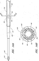
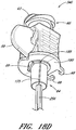
- FIGURES 19A-19E depict another example of a dilator 24H that includes additional elements to enhance the fluid flash-back feature of the access device 20.
- One additional element involves at least one wiper or seal that interacts with a needle (e.g., the needle 22 described in connection with the example illustrated in FIGURES 1-7 above) about which the dilator 24H is coaxially disposed to inhibit fluid uptake thorough a space occurring between the needle exterior (e.g., needle exterior surface 154 of FIGURE 8D ) and the dilator interior (e.g., dilator interior surface 152 of FIGURE 8D ).
- the seal feature can be incorporated into any of the previously described examples of the access device 20.
- the dilator can include multiple seals located along the length of the dilator. Such seals can be located in series to the proximal side of the dilator fenestration and/or the needle fenestration. Additional seals can be located on the distal side of such fenestration as well in some examples; however, in the illustrated example, the seal is depicted to the proximal side of both the dilator and needle fenestrations.
- the dilator 24H includes a sealing portion 250 that lies slightly proximal of a fenestration 74H on the dilator 24H.
- the sealing portion 250 is depicted as an inward protrusion that creates a narrowed region in the interior of the dilator 24H.
- the dilator 24H can form a seal with a needle (not shown) to separate the space between the dilator 24H and the needle into proximal and distal sections each lying to one side of the seal.
- One potential result is that, in examples where a fluid is intended to advance from the needle bore to a space between the dilator 24H and a sheath (e.g., the sheath 26 described in connection with the example illustrated in FIGURES 1-7 above), fluid leakage into the proximal space between the dilator 24H and the needle is reduced, as the body fluid is inhibited from passing proximally beyond the sealing portion 250.
- the sealing portion 250 can serve as a wiper, removing fluid (e.g., blood) from the surface of the distal portion of a needle as it is retracted into the dilator 24H.
- the sealing portion 250 can take a variety of cross-sectional shapes, including triangular (an example of which is illustrated in FIGURE 19C ), rounded or rectangular.
- the sealing portion 250 has a generally triangular cross-sectional shape formed in part by a tapering surface 252 that slopes inward preferably in a proximal direction.
- the tapering surface 252 intersects with a ledge 251 of the sealing portion 250.
- the ledge 251 lies generally perpendicular to a longitudinal axis of the dilator 24H; however, in other embodiments, the ledge 251 can lie at various angles relative to the longitudinal axis so that an angle formed between the tapering surface 252 and the ledge 251 can be acute, right or obtuse.
- the tapering surface 252 on the sealing portion 250 can assist movement of the needle through the dilator 24H in a proximal direction.
- the ledge 251 allows the sealing portion 250 to deflect proximally as a needle is passing through.
- the dimension of the inward projection of the sealing portion 250 preferably is not significantly less than, and is more preferably greater than half of the difference in diameters between the exterior of the needle and the interior of the dilator at the point of the fenestrations.
- the dilator 24H can include an expanded portion 260, formed with a taper 262 proximal of the sealing portion 250.
- the expanded portion 260 can reduce contact and friction between the dilator 24H and a needle (or other article for that matter) passing through the dilator 24H.
- a needle or other article passing through the dilator 24H can include a stop portion extending axially outward to engage the taper and inhibit further advancement of the article.
- the expanded portion 260 and its coinciding taper can define a limit on axial movement between the dilator 24H and a corresponding needle or other article.
- the distal end of the needle can lie to the proximal side of the sealing portion 250 in some examples, and can lie to the distal side of the sealing portion 250 in other examples. In either position, the absence or the reduction of fluid on proximal side of the seal lessens the amount of body fluid flowing through the dilator hub once the dilator has been withdrawn from the patient's body.
- the sealing portion 250 can be formed on the dilator in any of a wide variety of ways readily known to those skilled in the art.
- the sealing portion 250 can be formed during a dilator tipping process after the dilator has been extruded.
- An internal mandrel can be cut with an annular groove that has the inverse image of the sealing portion 250.
- the mandrel is then placed within dilator. As the material of the dilator's distal end is heated during the tipping process and then pressed into the desired exterior shape, the material will also be forced into the annular groove on the mandrel to form the sealing portion 250. After sufficient cooling, the dilator can be withdrawn.
- a sealing portion can take a different form.
- a needle can have an expanded exterior portion, forming an enlarged external diameter on the proximal side of its fenestration, similar to the enlarged internal diameter of the expanded portion 260 of the embodiment depicted in FIGURES 19A-19C .
- the needle can have a smaller external diameter at a distal portion and a larger external diameter at a distal portion.
- the enlarged diameter portion can engage or abut against the internal surface of the dilator (e.g., against taper 262) to form a sealing portion similar to that described above.
- the contact between the needle and dilator, forming a sealing portion can be formed between matching tapers such as the taper 262 on the dilator 24H and a similar external taper on the needle.
- the contact between the needle and the dilator can be on other surfaces, such as surfaces generally parallel with the longitudinal axis of the needle and dilator.
- the dilator 24H can have an inner diameter d1 in a portion distal from the fenestration 74H.
- a needle such as the needle 22J, or other needles such as the needle 22
- d1 can be less than d2; this can provide a number of advantages.
- the interference fit of the dilator 24H on the needle can put the dilator 24H under a radial or hoop load. This loading can increase the strength of the dilator 24H in an axial direction.
- the increased strength tends to reduce flaring, crimping or buckling of the material at the distal tip of the dilator when inserting the dilator through tissue (e.g., skin, muscle and/or vascular wall).
- tissue e.g., skin, muscle and/or vascular wall.
- the dilator can withstand axial forces that may otherwise deform the distal tip of the dilator. In some examples, this could cause a dilator to bunch, fold, or curl upon itself, increasing its cross-sectional area at said bunch or fold and inhibiting its functionality as a dilator. In other words, the deformed dilator becomes too difficult to insert into the patient.
- Providing the dilator with a smaller inner diameter d1 can increase the strength of the dilator, inhibiting the occurrence of such deformations.
- the inner diameter d1 of the dilator 24H can be smaller than the outer diameter d2 of a needle on which it mounts by approximately 15% or less.
- the outer diameter d2 of the needle can be approximately 15% larger than the inner diameter d1 of the dilator 24H.
- the inner diameter d4 of the dilator 24H is smaller than the outer diameter d2 by approximately 10% or less.
- the inner diameter d1 is smaller than the outer diameter d2 by approximately 2% to 4% of the outer diameter d2.
- the inner diameter d1 of the dilator 24H can be approximately 97% of the outer diameter d2 of a needle on which it mounts.
- the dilator tip can be beveled to provide a smoother dilation and to ensure further that the dilator tip does not deform upon entrance into the patient's body.
- the tip can have a taper or bevel at an angle ⁇ on each side (it is noted that the indicated angle ⁇ 's opposite angle is equal to ⁇ , and thus they are treated as the same herein).
- the beveled tip can reduce axial forces on the dilator 24H upon passage through tissue (e.g., skin).
- the angle ⁇ can be approximately 30 degrees. In other embodiments, the angle ⁇ can be between approximately 40 and 20 degrees.
- the dilator tip can taper at a shallower angle, as depicted in FIGURE 19D .
- the dilator can then taper at approximately 3 degrees, or alternatively at an angle less than approximately 3 degrees.
- the dilator 24H can include a ridge or protrusion 264 through which the fenestration 74H passes.
- the ridge 264 can separate a sheath overlapping the dilator, facilitating any flow through the fenestrations 74H into a space between the dilator 24H and said sheath.
- the ridge 264 can be generally thinner than the fenestration 74H.
- the ridge 264 can contact and separate the sheath while also leaving space for a fluid to flow around the ridge.
- the ridge 264 can be generally oriented in an axial, proximal-distal direction. However, in other examples the ridge 264 can be oriented in a circumferential direction or otherwise.
- FIGURES 20A and 20B depict a further example of a needle 22J that can be used in a manner similar to that of other needles described herein such as the needle 22.
- the needle 22J can comprise an echogenic portion 270 at the distal tip.
- the echogenic portion can comprise a material that scatters waves used in imaging, thus facilitating visualization of the needle under ultrasound.
- Other imaging techniques can also be used, such as using a needle having a radio-opaque portion facilitating visualization under X-rays or fluoroscopy.
- the echogenicity can be increased by sandblasting the portion 270 to roughen the surface.
- the tip can be sharpened after sandblasting, allowing the tip of the needle to be echogenic.
- Echogenicity can also be increased by modifying the internal material of the needle itself, such as by adding granular impurities. However, in some instances modification of the internal material may unacceptably compromise the structural integrity of the needle.
- the echogenicity or similar imaging compatibility can allow an operator to easily view the needle tip inside the body using a scanning technique such as ultrasound.
- a needle with an echogenic portion 270 can further lack fenestrations 56, 74, grooves 75, and/or surfactant. Further, in some examples with an echogenic portion 270, the access device can lack a flashback space or flash chamber.
- the needle 22J can have both an echogenic portion 270 and a fenestration 56 (in addition to other optional features described above).
- the needle 22J can include a contrast portion 280.
- the contrast portion 280 can have optical properties that improve the visibility of a fluid surrounding the contrast portion. For example, as described above, in some embodiments a body fluid can flow into a flashback space through the fenestration 56. The contrast portion 280 can then be positioned generally adjacent the flashback space and the contrast portion can have optical properties that contrast with the body fluid. Thus, the body fluid's entry into the flashback space can be more immediately apparent.
- the contrast portion 280 can have a color that contrasts with the color of blood, such as white, green, blue, etc.
- other optical properties can be varied such as by choosing between a reflective or matte finish.
- the contrast portion 280 can have be striped, checkered, dotted, or have some other pattern wherein the optical properties vary.
- the contrast portion 280 can have black and white stripes oriented axially and/or circumferentially along the needle. Where a pattern with different optical properties is utilized, the contrast portion 280 can be more generic to different fluids that may be distinguishable from one region of the contrast portion 280 but not another region.
- the varying optical properties can be applied in a variety of ways.
- the contrast portion 280 can be painted to have a particular color, finish, pattern, etc.
- portions of the needle can be polished or roughened to effect the reflective properties of the contrast portion 280.
- the contrast portion 280 can be formed from a different material, or have a different material applied to its surface, to yield different optical properties.
- the contrast portion 280 can be made echogenic, as in the echogenic portion 270 described above.
- the contrast portion 280 can be positioned just proximal from the fenestration 56 and extend a distance less than the entire distance of the needle 22J. This position can generally correspond to the beginning of a flashback space that may also be just proximal of the fenestration 56. However, in other examples the position of either or both the flashback space and the contrast portion 280 can vary. For example, in some examples the contrast portion 280 can span across the fenestration 56, or can be offset some distance therefrom. In further examples, the contrast portion 280 can extend to the needle hub or can span the entire needle body. As depicted, the contrast portion 280 can span circumferentially about the entire needle. However, in some examples the contrast portion 280 can be positioned only along an angularly reduced portion of the needle body, such as an angular portion having an angular span corresponding to the angular span of the fenestration 56.
- the dilator can have corresponding portions that are clear, translucent, transparent, or semi-opaque, such that the contrast portion 280 can be viewable from outside the access device. Then, as a fluid such as a body fluid enters the flashback space an observer can see both the contrast portion 280 and the body fluid as it enters the flashback space to occlude the contrast portion 280. The contrast in optical properties between the fluid and the contrast portion 280 can then facilitate the visual detection of the fluid's entry.
- the flashback can be enhanced or accelerated by sealing off or restricting air flow from the space between the needle body and the dilator body.
- fluid leakage e.g., air egress
- a sealing piece such as a washer between the needle and dilator hubs. The washer reduces any fluid flow that might occur between a dilator and needle at their abutting hubs.
- a trapped air column can form between the dilator and needle that inhibits the flow of a body fluid (e.g., blood) into the space between the needle and dilator.
- the body fluid flow can thus be diverted, e.g., into a dilator fenestration 74H and into a space between a dilator and sheath.
- the washer can be an elastic material, such as silicone.
- the washer can mount on the needle and have a planar or an o-ring-like shape.
- a flashback space can be provided between a needle and a dilator. As between the dilator and the sheath, as discussed above, a channel can be formed between the needle and the dilator that can receive blood or other fluids through the needle fenestration 56.
- An example of such a flashback space is described in FIGURES 18B-18D and the accompanying text in Application No. PCT/US2009/037204, filed 13 March 2009 .
- a preassembled access device can optionally be provided with a needle 22J that does not include any fenestrations and that can (but need not) be echogenic (depicted in FIGURES 20A, 20B ), along with a guidewire, dilator, sheath, and associated hubs.
- the preassembled access device can be inserted inside packaging, in the preassembled state.
- An operator can insert the access device into a patient and stop the advancement of the needle once the needle enters a targeted body space, as viewed from outside the body by ultrasound, X-ray, or some other imaging technique.
- the preloaded guidewire can then pass through the needle into the body space.
- the dilator can be advanced over the needle into the body space.
- the needle can be withdrawn the patient and further actions can be taken to insert the sheath over the dilator, as described above in relation to other embodiments.
- an access device can also include a modified track 30K and guidewire hub 46K, as depicted in FIGURES 21A-22B .
- the track 30K and guidewire hub 46K can be substantially similar to the tracks and hubs discussed above, can be operated in a similar manner, and can be used similarly with other elements such as the needles, dilators, and sheaths described herein.
- the track 30K can generally define a third position 125K with some similarity to the third position 125 described above.
- the third position 125K can include a releasable coupling mechanism 130K that can engage with the guidewire hubs with corresponding parts, such as the guidewire hub 46K.
- the coupling mechanism 130K can include a coupling section 290 formed from a T-shaped projection extending from the track 30K.
- the T-shaped projection can additionally include two latch recesses, on each side of its base, generally toward a distal end of the coupling section 290.
- a corresponding guidewire hub 46K can have corresponding structure with the coupling section 290 to releasably connect thereto.
- the guidewire hub 46K can include a receiving section 296 that can be in the form of a recess.
- the recess can have a T-shaped cross-section at a proximal end to match the coupling section 290, as best depicted in FIGURE 22A .
- the receiving section can receive the base of the coupling section 290 along two tines that can terminate with latch projections 298.
- the latch projections 298 can interact with the latch recesses 292 on the coupling section 290 to form a reversible snap-fit between the track 30K and the guidewire hub 46K.
- the tines can include bending portions 302 (formed e.g. from thinned material, to facilitate the snap-fit.
- the receiving section 296 can include an end recess 300 in-line with the provided path provided for the coupling section 290 between the tines, such that when the latch recesses 292 and projections 298 interengage, the coupling section 290 can also enter the end recess 300.
- the connection between the track 30K and hub 46K can be further stabilized.
- the track can include a grip projection 294.
- the grip projection 294 can extend downward from the track 30K, opposite from the coupling section 290.
- the grip projection 294 can be generally circular with gripping ridges, but other structures and shapes are possible.
- the grip projection 294 can allow an operator of the access device to hold the proximale end of the track 30K in a pistol-type grip.
- a ring finger or middle finger can be positioned around the grip projection 294 to contact it on the distal side. The thumb of the same hand can then be placed on the proximal end of a guidewire hub 46K coupled in the third position 125K.
- a similar grip projection can be applied to other tracks, such as the track 30 described above. Further, similar grip projections can be applied to other elements, such as a needle. Applying a grip projection to the needle can, for example, allow a needle to be easily gripped and moved along a track as described herein.
- a modified sheath 26L can be combined with the other elements described herein.
- the sheath 26L can be a splittable sheath.
- the sheath 26L can have two halves along a separation line 330, although in other embodiments the sheath can split into 3 or more pieces.
- the two halves can be symmetrical, integrally formed, and be detachable in some examples, as further discussed below. However, in other examples the halves can be asymmetrical, separately formed, or otherwise.
- the halves can be indwelling, non-detachable, and in further examples may lack any features indicating any well-defined half, third, or smaller section (symmetrical or otherwise).
- the two halves can form a sheath body 40L and a sheath hub 42L.
- the sheath body 40L can have a generally extended form and be configured to extend into a body space.
- the sheath hub 42L can locate on a proximal end of the sheath 26 and attach to a proximal end of the sheath body 40L
- Both the sheath body 40L and the sheath hub 42L can be splittable, such that the two halves of the sheath 26L can be separated.
- the sheath body 40L and/or the sheath hub 42L can comprise slight perforations defining the separation line 330 along which they can separate. They can comprise a groove, a series of indentations, regions of thinned/weakened material, or other features that can encourage splitting at pre-determined locations.
- the sheath 26L can be configured to separate along a line 330 generally parallel to a longitudinal axis of the sheath; but this line can differ.
- the sheath 26L can have two separation lines 330, allowing the sheath to separate completely into two halves.
- the sheath 26L can have only one separation line 330 and the sheath can be configured to fold open along a fold line where a second separation line could otherwise be.
- Similar separation lines 330 can be applied to embodiment sheaths having 3 or more sections. Separation along the separation line 330 can be accomplished by tearing, breaking, cracking, unzipping, or the like.
- the sheath hub 42L can be generally rigid.
- the sheath hub can comprise features to facilitate connection to other hubs or devices, such as the dilator hubs and needle hubs discussed above.
- the sheath 26L also can have a lip 95L, allowing engagement with other elements described above, such as the dilator 24, in a manner similar to the sheath 26.
- the sheath hub 42 can comprise a variety of other features such as gripping surfaces along tabs 320.
- each tab is generally centered on a portion of the sheath hub 42 that eventually separates. Accordingly, as depicted there are two tabs 320 centered on each half of the sheath hub 42L.
- the tabs 320 can be gripped by the hands of an operator to separate the halves of the sheath hub 42L. When the halves of the sheath hub 42L connect to respective halves of the sheath body 40L, separating the tabs 320 can separate the entire sheath 26L into the two halves.
- the sheath hub 42L can additionally include a ridge 325 toward a distal end of the hub.
- the ridge 325 can facilitate gripping of the hub 42L.
- the ridge 325 can receive a tubular or cylindrical cover that can extend over the distal portions of the sheath, dilator, and needle to protect the tip, and press onto the ridge 325.
- the ridge 325 can hold the cover in place.
- FIGURES 24A , 24B depict a sheath 26M according to the present invention, which has certain similarities to the sheath 26L.
- the interior of the sheath 26M forms a central cavity 342 extending along the longitudinal axis of the sheath 26M.
- the central cavity 342 is configured to receive a needle, dilator, or any other item desired to pass through the cavity and into a body space, with further detailed examples described herein.
- the cavity 342 can include a space through which a body fluid can flow, as described above.
- the central cavity 342 additionally includes a valve comprised of two or more plate bodies 204, 206 (depicted as circular discs), the valve able to stop the flow of a body fluid through the space.
- a similar valve can be included with the sheath 26L, or other sheaths described herein.
- One plate of the valve is a flexible plate body 344 connected to one of the halves of the sheath 26M.
- the flexible plate body 344 extends into the central cavity 342 from the half.
- the flexible plate body 344 can comprise polyisoprene, silicone, polyurethane, other elastic polymers, or other suitable biocompatible materials. It may be preferable to utilize a material that does not cold set, such that a needle, dilator, catheter, or other medical article can be packaged together, within the sheath 26M without compromising the valve features.
- the flexible plate body 344 can have a siliconized surface, facilitating low-friction sliding of various elements along its surface.
- the flexible plate body 344 can be substantially solid and not include any holes, slits, or other discontinuities. As also depicted, the flexible plate body can have a circular shape. However, in other embodiments the flexible plate body can include slits, holes, or other discontinuities, and/or can have other shapes that do not necessarily define a circular arc around its outer edge.
- the other plate body is a rigid plate body 346 on the other half of the sheath 26M.
- the rigid plate body 346 can be semi-circular and includes a generally circular relief 347 on its central end.
- the relief 347 is generally centered along the longitudinal axis of the sheath 26M. As depicted, the relief 347 can span approximately 270 degrees, but in other embodiments it can span a greater or lesser angle. In some embodiments the relief 347 can span 180 degrees, making the relief semicircular. In other embodiments the relief 347 can have other shapes, generally chosen to match a corresponding medical article to be passed through (as further discussed below).
- the rigid plate body can also have a variety of different shapes that do not define circular arcs along the outer edge.
- the rigid plate 346 can have a shape with varying vertical width.
- the rigid plate 346 can be funnel-shaped (optionally, with a relief 347), guiding an item inserted toward its center.
- the relief 347 can be sized just slightly larger than the width of an item intended to be received. Thus, if the sheath 26M is split with an item still passing through the rigid plate 346, the item can escape the rigid plate by passing through the relief 347.
- a minimally-sized relief 347 can substantially improve the quality of the seal provided.
- the two plate bodies 344, 346 overlap, such that they together form a seal along the central cavity 342.
- the flexible plate body 344 can extend beyond the remainder of its respective sheath hub half to overlap with at least the relief 347.
- the rigid plate body 346 can extend beyond its respective sheath hub half in a similar manner, or both can extend beyond their hubs.
- the hub halves can overlap, and potentially neither of the plate bodies 344, 346 can extend beyond their respective hubs.
- the flexible plate body 344 can be distal relative to the proximal plate body 346.
- the rigid plate body 346 can prevent proximal bending of the flexible plate body 344, and thus resist cracking due to a larger pressure distal from the seal.
- this arrangement can advantageously allow the insertion of various articles such as a needle or dilator.
- the article can be guided to the center of the sheath 26M by the relief 347, and in some embodiments this can be facilitated with a funnel-shaped relief.
- the relief 347 can generally match the article, such that the relief can form a partial seal with the article.
- two semi-circular, rigid plate bodies 344 can be provided, one on each half of the sheath 26M to form a complete seal spanning a full 360 degrees about a medical article passing through two semi-circular reliefs 347.
- the flexible plate body 344 can comprise additional structure that increases its resiliency.
- the flexible plate body 344 can include a shape-memory structure biased or pre-stressed against the rigid plate body 346.
- the shape-memory structure can be an alloy such as Nitinol or the like.
- the resulting seal can have a cracking pressure in a distal direction of approximately 20 centimeters of water or more.
- the biasing, pre-stressing, cracking pressure, and other results described herein can also occur absent the additional structure.
- the flexible plate body 344 can be formed from a resilient material, facilitating a retraction back to the initial position.
- the material properties of the flexible plate body 344 can allow the plate to bend.
- the flexible plate body 344 can have a fold line 349 along which it can bend. It may be preferable for this fold line to correspond with edges of the sheath hub half, as depicted in Figure 2 , extending from one end of the sheath hub half to another end.
- the flexible plate body 344 can have regions of thinner/weaker material that allow the plate to bend (but not break) at a desirable location.
- the flexible plate body 344 can be substantially rigid in all except a designated folding region that is resiliently flexible.
- the fold line or folding region can be formed from thinner/weaker material, perforations, grooves, or some other structure.
- an additional shape-memory structure can define a bending area or region.
- the flexible plate body 344 can attach to the sheath 26M by a variety of means. In some embodiments it can be glued or bonded to the sheath 26M. In other embodiments, the flexible plate body 344 can attach to the sheath 26M by molding or overmoulding. In further embodiments, the flexible plate 344 can be molded integrally with the sheath 26M (or a portion thereof such as the sheath hub half). When formed integrally, it may be desirable to give the hub 42M a substantially greater thickness than the flexible plate body 344, such that the hub maintains a higher rigidity.
- the flexible plate body 344 can attach to the sheath 26M by a mechanical compression, such as where the sheath hub 42M includes a groove that receives the plate and allows it to be press-fit into position.
- the rigid plate body 346 can be formed and attached to the sheath 26M by similar mechanisms. In one preferred embodiment, the rigid plate 346 can be integral with the sheath hub half. Further, the flexible plate body 344 can be overmoulded onto the sheath 26M.
- FIG. 25A-25I Alternative embodiment of a splittable sheath hub 42N is depicted in Figures 25A-25I .
- the embodiments of Figures 25A-25I can be generally similar to the embodiments discussed above, with optional differences discussed below. It will be understood that the sheaths discussed above, non-exclusively including the sheaths 26L and 26M, can be modified to include the valve elements discussed herein.
- the sheath hub 42N can include elements described in relation to the sheaths described above. For example, in some embodiments the sheath hub 42N can include a lip similar to the lips 95, 95L, to facilitate attachment to other elements.
- the cavity 342 at a proximal end can have a triangular shape with a central bulge, when looking through the cavity.
- the sheath hub 42N can generally define two halves, each with a corresponding tab 320.
- a pair of grooves 352 can be opposed and centered along the sheath hub 42N. In operation, pulling the tabs 320 can cause the sheath hub 42N to separate, as described in relation to other embodiments, along the grooves 352.
- the cavity 342 is best depicted in Figures 25A-25C .
- the cavity can have the above-described triangular shape.
- the cavity 342 can be generally extended in a direction perpendicular to the grooves 352.
- the cavity 342 can narrow to a generally circular cross-section.
- the size of the distal portion of the cavity 342 can generally correspond to a maximum size of an article intended to pass through the sheath hub 42, and the size of the proximal portion of the cavity can generally correspond to the plate bodies 344, 346 that can be inserted from that side.
- the cavity 342 can form other shapes, such as a generally reverse shape when the plate bodies are inserted from the opposite side.
- the cavity 342 can define one or more receiving portions. As depicted, the receiving portions are near the edge of the cavity 342 and receive the anchors 350, 351 of the plate bodies (as further described below).
- the cavity 342 can include three receiving portions, one corresponding to an anchor 351 of the rigid plate body 346 and a pair corresponding to anchors 350 of the flexible plate body 344.
- the receiving portions (and similarly the anchors) are generally opposite each other inside the cavity 342. However, in other embodiments they can be otherwise arranged. For example, in some embodiments both anchors 350 of the flexible plate body 344 can enter a single enlarged receiving portion.
- a different number of anchors can be provided, along with a corresponding number of receiving portions.
- the receiving portion can be one annular groove, such that the anchors/plates can be arranged arbitrarily in a modular fashion (e.g. the plate bodies can be selected from a group of possible bodies, each of which capable of fitting within a single sheath hub).
- the plate bodies 344, 346 are best depicted in Figures 25D-25F .
- the flexible plate body 344 can have two anchors 350 at a first end of the body.
- the anchors 350 can extend from a generally planar portion and terminate with a rounded-portion.
- the planar portion can narrow as it extends from the anchors 350 and then bulge back outward to form a circular shape, more generally forming a key-hole shape in the depicted embodiment (as described above in relation to other embodiments, other shapes are possible).
- the circular portion can be generally flexible, such that it can bend when an article pushes against it.
- the flexible plate body 344 can include a wedge portion 205 on the planar portion opposite the anchors 350.
- the wedge portion 205 can be thickest at the anchors 350 and taper downwards in the direction of the circular portion. This formation can generally resist upward bending of the flexible plate body 344 (as such bending would compress the wedge portion 205) but substantially allow downward bending of the plate body (extending the wedge portion 205).
- the rigid plate body 346 can have a single anchor 351 similar to the anchors 350 of the flexible plate body 344.
- the rigid plate body 346 can additionally include a planar portion.
- the planar portion can generally match the anchor 351 at that portion and then expand as it extends to a rounded portion defining a partial circle.
- the partial circle can define a radius approximately equal to the radius of the circular portion of the flexible plate body 344 and be configured to generally align with that circular portion when assembled.
- the cutout 347 can generally align with the wedge portion 345, such that the wedge enters the cutout when assembled.
- the cutout can define a semicircle.
- the radius of the semicircle can be configured to generally match that of an article intended to pass therethrough.
- the cutout 347 can take other shapes depending on its intended use (as also described above regarding other embodiments).
- FIGS 25G , 25H depict an alternative embodiment of the flexible plate body 344 that can also be used with the sheaths and sheath hubs described above.
- the flexible plate body 344 can include two planar portions 344A, 344B.
- the planar portions 344A, 344B can be of the same shape and material, as depicted, but in other embodiments they can have differing properties.
- both of the planar portions 344A, 344B can cover the relief 347 of the rigid plate body 346.
- the planar portions 344A, 344B can rest on opposite sides of the rigid plate body 346, receiving the rigid plate body therebetween.
- the resulting valve in this arrangement it is possible for the resulting valve to be resilient to a reduced pressure at a distal (lower) end of the assembly, as well as the reverse.
- a user can lift the upper planar portion 344A before inserting an item through the assembly, as otherwise described above.
- Figure 25I depicts further alternative embodiments of flexible plate bodies 344C, 344D.
- two flexible plate bodies 344C, 344D can be provided.
- the plate bodies can each include slits through which an item can pass through, maintaining a seal as the item passes through.
- the slits can be at an angle to each other, but in other embodiments they can be parallel.
- the two plate bodies 344C, 344D can be on separate inserts. However, like the embodiment of Figures 25G and 25H , they can also be on a single piece in other embodiments.
- the planar portions 344C, 344D can be used in conjunction with the rigid plate body 346 (as described above).
- planar portions 344C, 344D, and 346 can each be, as depicted, in the form of inserts with anchors 350C, 350D, and 351 and corresponding receiving sections. However, in other embodiments some or all of these elements can be integral with or overmolded onto the remaining assembly.
- the sheath hub depicted in Figures 25A-25C can be assembled in stages (similar methods for assembly can be applied to other embodiments described herein, such as said sheath hub combined with the alternative plate bodies).
- the hub can be molded, cut, or otherwise formed to the form depicted.
- the form can include receiving portions (described above) in the cavity 342 configured to form a press-fit with the anchors 350, 351.
- the plate bodies 344, 346 can thus be inserted distally from a proximal position.
- the flexible body 344 can enter first and the rigid body 346 can follow.
- one or more of these elements can be integral with or overmolded onto the sheath hub.
- the plate bodies can insert from a different side or in a different order, depending on the construction of the sheath hub.
- the sheath hub can then be attached to a sheath body (if not already done so) and any remaining assembly steps can be performed.
- an operator can insert a medical article through the sheath hub, such as a needle, dilator, catheter, or the like.
- the article can enter the cavity 342 from a proximal end. It can then pass through the relief 347 in the rigid plate body 346 and press against the flexible plate body 344 to proceed further into the sheath hub.
- Other articles can be inserted and removed in a similar manner.
- the sheath hub When the sheath hub is splittable, it can beneficially be split with the medical article inside, without disturbing the medical article.
- the sheath hub when an operator actuates the tabs 320 to split the sheath, the sheath hub can break such that the plate bodies 344, 346 remain with opposite halves. The medical article can exit the rigid plate body 346 through the cut out 347. Accordingly, the sheath hub and the corresponding seal can be split without disturbing a medical article inside. It will be clear from the disclosure herein that a similar procedure can be performed with other embodiments of the sheath hub.
- the needle preferably consists of ceramic, a rigid polymer, or a metal such as stainless steel, nitinol, or the like.
- the other elements can be formed of suitable polymeric materials, such as polycarbonate, nylon, polyethylene, high-density polyethylene, polypropylene, fluoropolymers and copolymers such as perfluoro (ethylene-propylene) copolymer, polyurethane polymers or co-polymers.
- the dilator can be formed from nylon.
- the present access device can be used to place a catheter at other locations within a patient's body.
- the access device can be used as or with a variety of catheters to drain fluids from abscesses, to drain air from a pneumotorax, and to access the peritoneal cavity.
- body fluids flow into the viewing space to indicate when the needle has been properly placed.
Landscapes
- Health & Medical Sciences (AREA)
- Life Sciences & Earth Sciences (AREA)
- Heart & Thoracic Surgery (AREA)
- Public Health (AREA)
- Biomedical Technology (AREA)
- Engineering & Computer Science (AREA)
- Animal Behavior & Ethology (AREA)
- General Health & Medical Sciences (AREA)
- Veterinary Medicine (AREA)
- Anesthesiology (AREA)
- Hematology (AREA)
- Pulmonology (AREA)
- Biophysics (AREA)
- Surgery (AREA)
- Pathology (AREA)
- Nuclear Medicine, Radiotherapy & Molecular Imaging (AREA)
- Medical Informatics (AREA)
- Molecular Biology (AREA)
- Media Introduction/Drainage Providing Device (AREA)
- Surgical Instruments (AREA)
- Infusion, Injection, And Reservoir Apparatuses (AREA)
Description
- This invention is generally directed to access devices for introducing and/or delivering a medical article (such as, for example, a catheter, cannula, sheath, etc.) into a body space, such as, for example, an artery, vein, vessel, body cavity, or drainage site.
- A preferred non-surgical method for inserting a catheter or vascular sheath into a blood vessel involves the use of the Seldinger or a modified Seldinger technique, which includes an access needle that is inserted into a patient's blood vessel. A guidewire is inserted through the needle and into the vessel. The needle is removed, and a dilator and sheath in combination or separately are then inserted over the guidewire. The dilator and sheath, together or separately, are then inserted a short distance through the tissue into the vessel, after which the dilator and guidewire are removed and discarded. A catheter or other medical article may then be inserted through the sheath into the vessel to a desired location, or the sheath may simply be left in the vessel. When a catheter or other medical article is inserted into the vessel, the sheath is often removed thereafter. To facilitate this removal, the sheath is sometimes a splittable sheath.
- Prior to insertion of this medical article through the sheath, there can be a possibility of a backflow, through the sheath, from the blood vessel. This can potentially contaminate the area surrounding the sheath with a backflow fluid such as blood. Thus, some vascular access devices are known to include a hemostatic valve. In some situations said valves are also made splittable with a splittable sheath. These constructions can often be difficult to manufacture, assemble, package, or be generally ineffective. Such an exemplary construction is given in
US5397311 . Thus, there exists a need for an improved vascular access device, especially one that includes an economical, effective, and efficient splittable valve. - The described embodiments involve several features for an access device useful for the delivery of a catheter or sheath into a space within a patient's body, such as, for example, a blood vessel or drainage site. Without limiting the scope of this invention, its more prominent features will be discussed briefly. After considering this discussion, and particularly after reading the Detailed Description of the Preferred Embodiments section below in combination with this section, one will understand how the features and aspects of these embodiments provide several advantages over prior access devices.
- As defined in
claim 1, a splitable sheath includes sheath body and a sheath hub. The sheath body having a generally flexible tubular structure, a proximal end, and a distal end. Further, the sheath body defines a longitudinal axis through the tubular structure. The sheath hub extends from the proximal end of the sheath body and defines a longitudinal axis generally aligned with the axis of the sheath body. The sheath body and sheath hub form a central cavity along their respective axes. Within the cavity the sheath hub includes two plate bodies: a flexible plate body and a rigid plate body. - The rigid body comprising a relief generally centered on the longitudinal axis, wherein the flexible plate and the rigid plate overlap to substantially seal the central cavity. As defined in claim 11, the invention also defines an access device including a needle, a dilator, and a sheath. The dilator is coaxially mounted on the needle and includes a dilator shaft and a dilator hub. The sheath coaxially mounts on the dilator and includes a sheath body and a sheath hub. The sheath body has a proximal end and a distal end, and a distal end of the sheath hub extends from a proximal end of the sheath body. Further, the sheath hub reversibly attaches to the dilator hub at a proximal end of the sheath hub. The sheath body and the sheath hub form a central cavity. Additionally, the sheath hub includes a flexible plate body and a rigid plate body, wherein the flexible plate body and rigid plate body allow the needle and dilator to extend through the cavity, and the plate bodies overlap to substantially seal the central cavity when the needle and dilator are removed from the cavity.
- These and other aspects of the present invention will become readily apparent to those skilled in the art from the following detailed description of the preferred embodiments, which refers to the attached figures.
- These and other features, aspects, and advantages of the access device disclosed herein are described below with reference to the drawings of preferred embodiments, which are intended to illustrate and not to limit the invention. Additionally, from figure to figure, the same reference numerals have been used to designate the same components of an illustrated embodiment. Like components between the illustrated embodiments are similarly noted as the same reference numbers with a letter suffix to indicate another embodiment. The following is a brief description of each of the drawings.
-
FIGURE 1A is a perspective view of an example of an access device configured in accordance with the present invention and shows a pre-loaded guidewire section coaxially aligned with a needle, a dilator, and a medical article. -
FIGURE 1B is a plan view of the example depicted inFIGURE 1A . -
FIGURE 2A is a plan view of the needle fromFIGURE 1A and shows a fenestration near a distal end. -
FIGURE 2B is a side view of the needle fromFIGURE 1A and shows a fin near a proximal end. -
FIGURE 2C is a cross-sectional view taken along thelines 2C-2C inFIGURE 2A . -
FIGURE 2D is an enlarged plan view of a portion of the needle ofFIGURE 2A and shows the fenestration. -
FIGURE 2E is an enlarged plan view of the needle hub of the needle ofFIGURE 2A . -
FIGURE 2F is an enlarged side view of the needle hub of the needle ofFIGURE 2A . -
FIGURE 2G is an enlarged proximal end view of the needle hub of the needle ofFIGURE 2A . -
FIGURE 3A is a plan view of the dilator fromFIGURE 1A and shows a fenestration near a distal end.FIGURE 3A also shows longitudinally arranged grooves in the luer surface for venting air from between the dilator and sheath. -
FIGURE 3B is a cross-sectional view taken along thelines 3B-3B inFIGURE 3A . -
FIGURE 3C is an enlarged plan view of a portion of the dilator fromFIGURE 3A and shows the fenestration and longitudinal channel. -
FIGURE 3D is an enlarged end view of the dilator hub fromFIGURE 3A . -
FIGURE 3E is a perspective view of another dilator hub that includes a locking spin nut configured to secure to a sheath that has a corresponding screw thread. -
FIGURE 3F is a cross-sectional view taken along thelines 3F-3F inFIGURE 3A and shows the grooves equally spaced about the circumference of the luer surface. -
FIGURE 4A is a plan view of the sheath fromFIGURE 1A and shows a sheath hub connected to a proximal end of a sheath. -
FIGURE 4B is a cross-sectional view taken along thelines 4B-4B inFIGURE 4A . -
FIGURE 4C is an enlarged end view of the sheath fromFIGURE 4A . -
FIGURE 4D is an enlarged perspective view of a proximal portion of the sheath fromFIGURE 4A . -
FIGURE 5A is a perspective view of the guidewire section fromFIGURE 1A and shows a guidewire hub connected to a proximal end of a guidewire. -
FIGURE 5B is a plan view of the guidewire section as depicted inFIGURE 5A . -
FIGURE 6A is a perspective view of a track fromFIGURE 1A . -
FIGURE 6B is a plan view of the track inFIGURE 6A and shows a locking mechanism for locking the needle relative to the dilator. -
FIGURE 6C is a side view of the track inFIGURE 6B . -
FIGURE 6D an enlarged view of the locking mechanism fromFIGURE 6B . -
FIGURE 6E is an enlarged view of another locking mechanism that locks the guidewire section in a pre-loaded state. -
FIGURE 7A is a plan view of the access device fromFIGURE 1A and shows the locking mechanism fromFIGURE 6E with the guidewire section locked to the track in the pre-loaded state. -
FIGURE 7B is a side view of the access device and locking mechanism fromFIGURE 7A . -
FIGURE 7C is a cross-sectional view through the access device ofFIGURE 7A and shows the guidewire hub disposed between an element and stop of the track. -
FIGURE 7D is an enlarged end view of the access device fromFIGURE 7B and shows two arms extending from the track and around at least a portion of the guidewire hub. -
FIGURE 8A is a plan view of the embodiment depicted inFIGURE 1A illustrating the insertion of the distal end of the access device into a patient. -
FIGURE 8B is an enlarged view of the example depicted inFIGURE 8A focusing on the area of the access device adjacent to the patient. -
FIGURE 8C is an enlarged view of a portion of the example depicted inFIGURE 8B and illustrates the needle opening or fenestration aligned with the dilator opening or fenestration in hidden lines. -
FIGURE 8D is an enlarged cross-sectional view of a portion of the example depicted inFIGURE 8C and shows the needle opening or fenestration aligned with the dilator opening or fenestration so as to allow fluid to flow from inside the needle to a channel formed between the sheath and dilator. -
FIGURE 8E is a graph showing the rate fluid is drawn up a channel with a gap height width of 0,0508 mm (0,002 inches). -
FIGURE 8F is a graph showing the rate fluid is drawn up a channel with a gap height width of 0,0254 mm (0,001 inches). -
FIGURE 8G is a graph showing the rate fluid is drawn up a channel with a gap height width of 0,0127 mm (0,0005 inches) -
FIGURE 8H is an enlarged cross-sectional view of a portion of the example depicted inFIGURE 8C taken through a region distal of the channel in the dilator. -
FIGURE 8I is an enlarged view of the example depicted inFIGURE 8A focusing on the area where the needle hub is locked to the dilator hub when the needle hub is in the first position. -
FIGURE 8J is a cross-sectional view of the example depicted inFIGURE 8I . -
FIGURE 9A is a side view of the embodiment depicted inFIGURE 1A illustrating the guidewire advanced from the needle tip in a distal direction. -
FIGURE 9B is an enlarged view of the embodiment depicted inFIGURE 9A focusing on the area where the guidewire hub is locked to the needle hub when the needle hub is in the first position. -
FIGURE 9C is a cross-sectional view of the embodiment depicted inFIGURE 9B . -
FIGURE 10A is a side view of the example depicted inFIGURE 1A illustrating the dilator and sheath being advanced distally relative to the needle body from the position illustrated inFIGURE 9A . -
FIGURE 10B is an enlarged rear view of the example depicted inFIGURE 10A focusing on the area where the needle hub is locked to the track when the needle hub is in the second position. -
FIGURE 11A is a side view of the example depicted inFIGURE 1A illustrating the removal of the guidewire, needle body, and dilator from the sheath. -
FIGURE 11B is an enlarged view of the portion of the example illustrated inFIGURE 11A showing the needle tip covered by the dilator during removal of the guidewire, needle body, and dilator from the sheath. -
FIGURE 12A is an enlarged plan view that illustrates another example of the aligned openings or fenestrations in the needle and dilator. -
FIGURE 12B is an enlarged cross-sectional view alonglines 13B-13B inFIGURE 12A and shows the needle opening or fenestration aligned with the dilator opening or fenestration so as to allow fluid to flow from inside the needle to a channel formed between the sheath and dilator. -
FIGURE 13A is an enlarged plan view that illustrates another example of the aligned openings or fenestrations in the needle and dilator. -
FIGURE 13B is an enlarged cross-sectional view alonglines 13B-13B inFIGURE 13A and shows the needle opening or fenestration aligned with the dilator opening or fenestration so as to allow fluid to flow from inside the needle to a channel formed between the sheath and dilator -
FIGURE 14A is an enlarged plan view that illustrates another example of the channel formed between the dilator and the sheath. -
FIGURE 14B is a cross-sectional view alonglines 14B-14B inFIGURE 14A and shows the thickness of the channel extending into the sheath. -
FIGURE 15A is an enlarged plan view that illustrates another example of the channel formed between the dilator and the sheath. -
FIGURE 15B is a cross-sectional view alonglines 15B-15B inFIGURE 15A and shows the thickness of the channel extending into both the dilator and the sheath. -
FIGURE 16A is an enlarged plan view that illustrates another example of the channel formed between the dilator and the sheath. -
FIGURE 16B is a cross-sectional view alonglines 16B-16B inFIGURE 15A and shows a plurality of equally spaced channels in the form of splines extending into the dilator. -
FIGURE 17 is an enlarged cross-sectional view through another example of the access device and shows the channel formed between a sheath and a dilator that have dissimilar shapes. -
FIGURE 18A is an enlarged plan view of a portion of another example of the access device and illustrates another embodiment of a channel this time formed between the needle and the dilator. - FIGURE 18Bis an enlarged cross-sectional view through the example of
FIGURE 18A taken at 18B-18B. -
FIGURE 18C is an enlarged cross-sectional view through the example ofFIGURE 18A taken at 18C-18C. -
FIGURE 18D is an enlarged perspective view of a needle hub configured to form part of the needle depicted inFIGURE 18A . -
FIGURE 18E is a plan view of the dilator ofFIGURE 18A . -
FIGURE 19A is a plan view of a distal portion of another example of a dilator. -
FIGURE 19B is a cross-sectional view of the distal portion of the dilator ofFIGURE 19A , with a fenestration in phantom. -
FIGURE 19C is an enlarged view of a section of the dilator ofFIGURE 19B taken at 19C-19C. -
FIGURE 19D is an enlarged view of a section of the dilator ofFIGURE 19B taken at 19D-19D. -
FIGURE 19E is a side view of the dilator ofFIGURE 19A , with interior features in phantom. -
FIGURE 20A is a side view of another example of a needle. -
FIGURE 20B is an enlarged view of a distal end of the needle ofFigure 20A . -
FIGURE 21A is a perspective view of another example of a track. -
FIGURE 21B is a plan view of the track ofFIGURE 21A . -
FIGURE 21C is a side view of the track ofFIGURE 21A -
FIGURE 21D is an enlarged view of a section of the track ofFIGURE 21A taken at 21D-21D. -
FIGURE 22A is a perspective view of another example of a guidewire hub. -
FIGURE 22B is a bottom view of the guidewire hub ofFIGURE 22A . -
FIGURE 23A is a proximal end view of example of a sheath not covered by claims. -
FIGURE 23B is a plan view of the sheath ofFIGURE 23A . -
FIGURE 24A is an exploded perspective view of an embodiment of a splittable sheath according to the present invention. -
FIGURE 24B is an exploded top view of the sheath ofFIGURE 24A . -
FIGURE 25A is a top perspective view of an embodiment of a sheath hub. -
FIGURE 25B is a top view of the sheath hub ofFIGURE 25A . -
FIGURE 25C is a cross-sectional view of the sheath hub ofFIGURE 25A at 25C-25C . -
FIGURE 25D is a perspective view of two plate bodies of the sheath hub ofFIGURE 25A . -
FIGURE 25E is a perspective view of a one of the plate bodies ofFIGURE 25D . -
FIGURE 25F is a perspective view of the other plate body ofFIGURE 25D . -
FIGURE 25G is a side view of another embodiment of two plate bodies. -
FIGURE 25H is a perspective view of one of the plate bodies ofFIGURE 25G . -
FIGURE 25I is an exploded perspective view of two other embodiment plate bodies. - The present disclosure provides an access device for the delivery of a medical article (e.g., catheter or sheath) to a blood vessel or drainage site.
FIGURE 1A illustrates anaccess device 20 that is configured to be inserted into a blood vessel (e.g., a vein or an artery). While the access device is described below in this context (i.e., for vascular access), the access device also can be used to access and place a medical article (e.g., catheter or sheath) into other locations within a patient's body (e.g., a drainage site) and for other purposes (e.g., for draining an abscess). - The present example of the access device is disclosed in the context of placing an exemplary single-piece, tubular medical article into a body space within a patient. Once placed, the tubular article can then be used to receive other medical articles (e.g., catheters, guidewires, etc.) to provide access into the body space and/or be used to provide a passage way for introducing fluids into the body space or removing (e.g., draining) fluids from the body space. In the illustrated example the tubular medical article is a sheath or catheter that is configured primarily to provide a fluid passage into a vein.
-
FIGURES 1A and1B illustrated an example of anaccess device 20. Theaccess device 20 comprises aneedle 22, adilator 24, and asheath 26. In the illustrated embodiment, the access device also includes aguidewire section 28 and atrack 30. As best seen inFIGURE 1B , thedilator 24 is preferably coaxially mounted on theneedle 22, and thesheath 26 is coaxially mounted on thedilator 24. The telescoping nature of the access device's components can also be accomplished by arranging the components with their axes arranged substantially parallel rather than coaxially (e.g., a monorail-type design). - Each of these components includes a luminal fitting at a terminal end or transition (i.e., a hub) and elongated structure that extends from the fitting. Thus, in the illustrated embodiment, the
needle 22 includes aneedle body 32 that extends distally from theneedle hub 34, thedilator 24 includes adilator shaft 36 that extends distally from adilator hub 38, and thesheath 26 includes asheath body 40 that extends distally from asheath hub 42. Theguidewire section 28 comprises aguidewire 44 and preferably a guidewire hub orcap 46. In the illustrated embodiment, theguidewire hub 46 is disposed on the proximal end of theguidewire 44; however, in other applications, thehub 46 can be disposed at a location between the ends of theguidewire 44. -
FIGURES 2A-2G illustrate theneedle body 32 andneedle hub 34 of theneedle 22, which are configured in accordance with an example of the access device, in isolation from the other components of theaccess device 20. As best seen inFIGURES 2A and 2B , theneedle hub 34 is disposed on a proximal end of theneedle body 32. Theneedle body 32 terminates at a distal end near adistal portion 50 of theneedle 22, and theneedle hub 34 lies at aproximal portion 52 of theneedle 22. - The
needle body 32 preferably has an elongated tubular shape having a circular, constant-diameter inner bore and a circular, constant-diameter exterior surface. In other embodiments, however, theneedle body 32 can have other bore and exterior shapes (such as, for example, but without limitation, an oval cross-sectional shape). The interior or exterior of the needle can also include grooves or channels. The grooves or channels may guide fluids within the needle bore either around or to certain structures of theneedle 22 or within the needle 22 (e.g., around the guidewire). In some embodiments, the grooves or channels may assist in maintaining a desired orientation of theneedle 22 with respect to the dilator. - The
needle body 32 has a sufficiently long length to access a targeted subcutaneous body space and has a sufficient gauge size to withstand the insertion forces when accessing the body space without causing undue trauma. For many applications, the needle body can have a length between 3- 20 cm, and more preferably between 3-10 cm. For example, to access a body space (e.g., a vessel) in the thorax of an adult human, theneedle body 32 preferably has a length of 7 cm or greater, and more preferably has a length of 9 cm or greater, and most preferably has a length of 9 to 10 cm. The size of the needle preferably is 18 gauge or smaller, and more preferably between 18-28 gauge, and most preferably between 18-26 gauge for micro-puncture applications (peripheral IVs). For applications with a neonate, the length and gauge of theneedle body 32 should be significantly shorter and smaller, for example preferably between 3-4 cm and between 26-28 gauge. - As best seen in
FIGURES 2A and2D , theneedle body 32 includes at least one fenestration oropening 56 near a distal end of theneedle body 32. Thefenestration 56 extends through the wall of theneedle body 32 and can have a variety of shapes and orientations on theneedle body 32, as described in detail below. In addition, theneedle body 32 can have abevel tip 54 disposed on thedistal portion 50. - As is illustrated in
FIGURES 2A and 2B , afin 58 is preferably disposed at a circumferential location around theneedle hub 34 that is aligned with the circumferential locations of the bevel on the needle tip and the opening orfenestration 56 in the needle. That is, thefin 58 is indexed with the bevel and fenestration. During use, the physician or healthcare provider can determine the orientation of the beveled needle tip (and the fenestration 56) by noting the orientation of the exposedfin 58 even though the bevel is inside the vessel and the fenestration is covered by the sheath and/or dilator. For example, in the illustrated example, an orientation of thefin 58 away from the patient coincides with a bevel up orientation of the needle tip within the vessel. Thefenestration 56 is also on the same side as thefin 58, as seen inFIGURE 2C . - The
fin 58 also provides a grasping region to manipulate theneedle hub 34. For example, a physician or healthcare provider can place an index finger and thumb on the sides of thefin 58 to stabilize theneedle hub 34, relative to thedilator 24 and/orsheath 26. In the illustrated embodiment, as the dilator/sheath slides distally over the needle, theneedle hub 34 slides relatively along thetrack 30 between afirst position 121 and a second position 123 (example portions illustrated inFIGURE 6A ). Thefin 58 can be held when performing the insertion step (which will be described below). In addition, thefin 58 can be used to stabilize theneedle hub 34 while rotating thedilator hub 38. Furthermore, thefin 58 can be used by a physician or healthcare provider as an aid to grasp theaccess device 20 when theneedle hub 34 is disposed at any position along thetrack 30. -
FIGURE 2D is an enlarged view of the side opening orfenestration 56 in theneedle body 32. The one ormore fenestration 56 provides a path through the side of theneedle body 32. Thefenestration 56 illustrated inFIGURE 2D has an oblong shape. The shape of theside opening 56, however, is not limited to the illustrated embodiment and may be round, oblong, square, or another shape. - With specific reference now to
FIGURES 2E-2G , theneedle hub 34 preferably includes locking structures at the proximal portion and distal portion of theneedle hub 34. These locking structures may be a luer-thread-type or another type of connections. - The locking structure on the
proximal portion 52 of theneedle hub 34 allows the physician or healthcare provider to secure another medical article to the proximal end of theneedle hub 34. For example, theneedle hub 34 in the illustrated example includes an annular flange orlip 63. Thelip 63 is threaded to allow theneedle hub 34 to attach to other medical articles with a corresponding luer-nut locking feature. Additionally, a physician or healthcare provider may attach a syringe or monitoring equipment to the locking structure on the proximal end to perform other procedures as desired. Theneedle hub 34 can also include a septum at its proximal end and/or a side port if these features are desirably for a particular application. - The locking structure on the distal portion of the
needle hub 34 allows the physician or healthcare provider, for example, to lock theneedle hub 34 to thedilator hub 38 when theneedle hub 34 is in thefirst position 121. In the illustrated example, the locking structure includes alatch element 66 on theneedle hub 34. Thelatch element 66 releasably locks theneedle hub 34 to thedilator hub 38. The locking structure allows the healthcare provider to advance the needle into a patient while grasping theneedle hub 34, thedilator hub 38 or both. - As explained below in greater detail, the
guidewire 44 is introduced through ahollow portion 62 of theneedle hub 34, through theneedle body 32, and into a punctured vessel. Theguidewire 44 allows the healthcare provider to guide thedilator 24 andsheath 26 into the vessel. - The
needle hub 34 may also comprise twotangs 68 that allow theneedle hub 34 to slide along thetrack 30 between afirst position 121 and asecond position 123. While in the preferred embodiment the twotangs 68 of theneedle hub 34 are engaged with thetrack 30 between thefirst position 121 and thesecond position 123, in other examples theneedle hub 34 is only engaged with thetrack 30 over a portion of the length of thetrack 30 between thefirst position 121 and thesecond position 123. The sliding interconnection between thetrack 30 and theneedle hub 34 also can be accomplished using other cooperating structures (e.g., a corresponding pin and tail of dovetail connection). -
FIGURE 3A is a plan view of thedilator 24 of the example depicted inFIGURE 1A .Figure 3B is a cross-sectional view of thedilator 24 of the example depicted inFigure 3A , taken alongline 3B-3B. As shown inFIGURES 3A and 3B , the illustrateddilator 24 comprises adilator shaft 36, adilator hub 38, adistal region 70, and aproximal region 72. In the illustrated embodiment, thedilator shaft 36 includes a side openings orfenestrations 74; however, in other examples, thedilator shaft 36 can include fewer or greater numbers offenestrations 74. For example, thedilator shaft 36 may not include afenestration 74 where a blood flash chamber(s) is disposed within the dilator (as will be described in more detail below). - The
dilator hub 38 may comprise one or more vents. In the illustrated examples, the vents in thedilator hub 38 are formed bygrooves 75. Additionally, thedilator shaft 36 may comprise one or more longitudinal channels formed in the outer surface of thedilator shaft 36. In the illustrated example, the channel is an open channel. The side walls of the open channel are formed byridges 76. In the illustrated example, theridges 76 define generally smooth, arcuate exterior surfaces that interface with thesheath 26; however, in other embodiments, the ridges can have other shapes (e.g., can define more pronounced apexes). Once assembled within asheath body 40, the open channel in thedilator shaft 36 is closed by the inside diameter of thesheath body 40. -
FIGURE 3C is an enlarged plan view of a portion of the example illustrated inFigure 3A . As noted above, the illustrateddilator shaft 36 comprises one ormore side openings 74 and one or more channels formed betweenridges 76. The side opening orfenestration 74 provides a fluid path through the side of thedilator shaft 36. The shape of theside opening 74 is not limited to the illustrated embodiment and may be round, oblong, square, or have another shape. The opening orfenestration 74 illustrated inFIGURE 3C has an oblong shape. - In the illustrated example the
opening 74 in thedilator shaft 36 has an oblong shape with its major axis being non-parallel relative to the major axis of theoblong opening 56 in theneedle 22. For example theneedle opening 56 may extend in a longitudinal direction and thedilator opening 74 may extend in a circumferential direction or vice versa. In other words, the long axis of thedilator opening 74 is disposed generally perpendicular to the long axis of theneedle opening 56. As explained in connection with additional examples below, theseopenings needle fenestration 56 has a longer longitudinal dimension than the longitudinal dimension of thedilator fenestration 74. - The channel formed between the
ridges 76 extends in a proximal direction from a point distal to theopening 74. Theridges 76 in the illustrated example are disposed along thedilator shaft 36 and on opposite sides of thedilator shaft 36 so as to balance thedilator shaft 36 within the sheath. In the illustrated example, theridges 76 form two channels there between. Balancing the dilator within the sheath allows the dilator to apply equal pressure to the inside circumference of the sheath. - The
dilator hub 38 may include locking structures at theproximal region 72 and the distal region of thedilator 24. Each locking structure may be a luer type or other type of connection. In the illustrated embodiment, thedilator hub 38 comprises afirst luer connection 78, asecond luer connection 80, alip 77, and abase 79. Thefirst luer connection 78 engages to theneedle hub 34 on theneedle 22 illustrated inFIGURE 2E . Thesecond luer connection 80 is disposed distal to thefirst luer connection 78. In some examples the second luer connection 80 (e.g., a male luer slip connector) can be configured to engage to the sheath hub 42 (e.g., a female luer slip connector) on thesheath 26 illustrated inFIGURE 1A . Additionally, the male-female lure slip connectors on these components can be reversed. -
FIGURE 3D is an enlarged proximal end view of thedilator 24 ofFIGURE 3A . As shown most clearly inFIGURE 3D , thedilator hub 38 comprises anopening 82 that releasably engages thelatch element 66 on theneedle hub 34 illustrated inFIGURE 2E-2F to secure thedilator hub 38 to theneedle hub 34 when theneedle hub 34 is in thefirst position 121. Again, the male-female lure slip connectors on the dilator hub and theneedle hub 34 can also be reversed in other examples. - The color of the
dilator 24 may be selected to enhance the contrast between the blood or other fluid and thedilator 24. During blood flash, for example, blood is observed flowing between thedilator 24 and the sheath to confirm proper placement of the needle in a blood vessel. To increase the visibility of the fluid as the fluid flows between the sheath anddilator 24, the sheath is preferably manufactured from a clear or transparent material with thedilator 24 having a color that contrasts with the color of the fluid. For example, thedilator 24 may have a white color to enhance its contrast with red blood. Other colors ofdilator 24 could be employed depending on the color of the fluid and the degree of contrast desired. Further, only a portion of the dilator in the region of the blood flash can have the contrasting color with the remainder having a different color. For examples that have a channel formed between the needle anddilator 24, thedilator 24 may be manufactured of a clear or transparent material similar to the sheath to allow the physician to observe the blood flash through both the sheath anddilator 24. -
FIGURE 3E is an enlarged perspective view of another example of a dilator hub 38A. The dilator hub 38A is similar to thedilator hub 38 illustrated inFIGURE 3A except that the dilator hub 38A further includes a spin nut orcollar 84. The proximal end of thespin nut 84 rotates about anannular groove 73 in the dilator hub 38 (seeFIGURE 3A ). Once disposed within theannular groove 73, thespin nut 84 is inhibited from moving in the distal direction but is free to rotate about the dilator hub 38A. Thespin nut 84 can have an interengaging element that locks to a corresponding interengaging element on thesheath 26. In the illustrated embodiment, thespin nut 84 includes an internal thread which engages with an external thread on thesheath hub 42 on thesheath 26 illustrated inFIGURE 1A . - The
dilator 24 orsheath 26 may separately, or together, form one or more passages to allow air or gas to escape or vent from between thedilator 24 andsheath 26 and/or between the needle and the dilator. The one or more passages may further be sized to inhibit the flow of a liquid, such as blood, while allowing air to pass therethrough. The one or more passages may be in the wall of thesheath 26, the sheath hub, thedilator hub 38, an exposed section of the dilator shaft, and/or formed between adjacent surfaces of thedilator 24 andsheath 26. For example,FIGURE 3A shows longitudinally arrangedgrooves 75 that are formed between adjacent surfaces of thedilator 24 andsheath 26. Such venting passages can also be labyrinth. The adjacent surfaces form a luer slip connection between thesheath 26 anddilator 24. -
FIGURE 3F is a cross-sectional view taken alonglines 3F-3F inFIGURE 3A and shows thegrooves 75 equally spaced, though not required to be equally spaced, about the circumference of the luer slip surface. Thegrooves 75 are sized to allow air to escape from between the dilator and the medical article, such as a sheath, when the blood flash occurs. As mentioned above, the one or more passages need not be in the form of asurface groove 75 and instead may be in the form of an opening or passageway. - In the illustrated example, the one or more passages allow air to pass through the luer connection between the sheath and dilator hubs. In the illustrated example, a distal end of the
passage 75 is located on the distal side of the luer connection with the proximal end of thepassage 75 being located on the proximal side of the luer connection. - The one or more passages may be sized to filter blood or other liquid or may include a filter or other structure that inhibits the passage of a liquid while allowing the passage of air. For example, the sheath itself may include one or more passages in the form of small openings, pores or porous material. Depending on the size of the one or more passages and the expected size of the fluid molecules and formed elements (e.g. red blood cells), the one or more small openings, pores or porous material in the sheath can form a porous vent that allows air to pass yet retain blood.
- A method of manufacturing a ridged dilator will now be described. First, an extrusion process is used to create a long tubular body having one or more longitudinal grooves or channels on its outer diameter (OD) or within the substance of the dilator. The long tubular body exceeds the required length of a single dilator and preferably has a length that is many times greater than the length of a single dilator. A manufacturing die is employed in the extrusion process having geometry that reflects the desired geometry for the inside and outside diameters of the dilator and the thickness and circumferential span of the longitudinal grooves or channels or interior channels. In the illustrated embodiment of
FIGURES 1-11 , the long tubular body includes two longitudinal OD channels on opposite sides of the body to enhance the balance of the dilator within the sheath. However, a single channel can provide a visible indicator for the blood flash. The two channels preferably extend along the length of the extruded tubular body. While the illustrated example includes one or more channel disposed between the dilator and the sheath, one or more channels can in addition or in the alternative be formed between the needle and the dilator, within the dilator, and/or within the sheath. In some examples thedilator 24 thus is made partially or completely from clear, translucent, transparent, or semi-opaque material to visualize the fluid flash within the channel. - With reference back to the illustrated example, the extruded tubular body is cut to the appropriate length for a single dilator. In the preferred method, the two OD grooves extend for the entire length of the cut dilator.
- A tipping process is then employed on an end of the cut dilator to reform the tip. An end of the cut dilator is forced into a die/mandrel having geometry that matches the desired geometry of the tip of the finished dilator. The desired geometry is selected depending on, for example, the inside diameter of the sheath. It is desirable for the sheath and dilator to form a close fit or seal near the tip to promote blood flow in the proximal direction up the channel formed between the grooved dilator and sheath. Preferably, the OD of the dilator in the tip region tapers in the distal direction.
- When in the die/mandrel, thermal energy is applied to the tip to reform the tip to match the die/mandrel. The thermal energy may be applied by any known technique, including using radiant heating from an infrared or RF heat source. As part of the tipping process, the dilator in the tip region is reformed so that the grooves are essentially removed. With the grooves removed, the dilator is able to form the close fit or seal with the sheath near the tip. The grooves are maintained along the remainder of the dilator on the proximal side of the location where the tip of the
sheath 26 sits on the dilator. After removal from the die/mandrel, the tip end of the dilator may be cleaned and cut as necessary to remove any manufacturing remnants. - The one or more fenestrations in the dilator is cut through the dilator near the tip region and in or near the groove. Each fenestration may be cut by any known means, including a drill or laser. Further, the cutting device may be moved with respect to the dilator or vice versa to achieve an oblong or other shape for the fenestration.
- The end of the dilator opposite from the tip end can be flared to facilitate over molding the dilator hub onto the dilator.
-
FIGURE 4A is a plan view of thesheath 26 of the example depicted inFIGURE 1A .Figure 4B is a cross-sectional view of thesheath 26 of the embodiment depicted inFigure 4A , taken alongline 4B-4B.FIGURE 4C is an enlarged proximal end view of thesheath 26 ofFIGURE 4A .Figure 4D is an enlarged perspective view of thesheath hub 42 of thesheath 26 ofFIGURE 4A . As shown inFIGURES 4A-4D , thesheath 26 may comprise asheath body 40, asheath hub 42, adistal portion 90, and aproximal region 92. Thesheath body 40 may be made partially or completely from clear, translucent, transparent, or semi-opaque material. Thesheath body 40 can also include one or more radio opaque markers, such as, for example, barium sulfate stripes. In a preferred example, the sheath includes two such radio opaque stripes disposed on diametrically opposite sides of thebody 40. - The
sheath body 40 may be a single piece sheath through which a catheter or other medical article (e.g., a guidewire) is inserted into the vessel. In such an example, thesheath body 40 forms a conduit for insertion of the catheter or other medical article (e.g., a guidewire). In addition to providing a conduit, the sheath or a portion of the sheath can form a lumen that is in addition to the lumen(s) of the catheter. For example, an equivalent to a triple lumen catheter can be formed by inserting a dual lumen catheter through thesheath body 40 with thesheath body 40 itself forming a third lumen. - It may be advantageous to remove a portion or the
entire sheath body 40 depending on the type of catheter or medical article that is to be inserted into the vessel after employing theaccess device 20. For example, after the catheter or other medical article is inserted into the vessel, a portion of thesheath body 40 can be separated or peeled-away and removed. A peel-away sheath can include perforations, serrations, skives, or other structures, or include other materials (e.g., PTFE with bismuth) to allow the physician or healthcare provider to remove easily a portion or theentire sheath body 40. - The
sheath hub 42 may include a luer slip connection and alock member 94. The lockingmember 94 may comprise a locking or attaching structure that mates or engages with a corresponding structure. For example, thelock member 94 can be aluer connection 94 which can be configured to engage with thesecond luer connection 80 of thedilator hub 38. - The
sheath hub 42, as best seen inFIGURE 4C and4D , preferably is designed so that the locking mechanism orsecond luer connection 80 of thedilator hub 38 can enter thesheath hub 42 substantially unobstructed. However, in use, once the sheath hub 53 is placed at a desired location over thedilator shaft 36, the physician or healthcare provider can push, pull, or twist thesheath hub 42 and possibly disengage or engage the lockingmember 94 with a corresponding connector on another medical article. The lockingmember 94 can be, for example, a luer connection, a protruding bump, dent, etc., that creates a mechanical fit so that thedilator hub 38 and thesheath hub 42 are releasably interlocked. In the illustrated embodiment, the lockingmember 94 of thesheath hub 42 comprises a luer connection. Thesheath hub 42 preferably engages with the correspondingsecond luer connection 80 on thedilator hub 38. Preferably, the locked position can be disengaged or engaged by pulling, squeezing, pushing or twisting thedilator hub 38 relative to thesheath hub 42. - In some examples, the
sheath hub 42 can comprise alip 95. Thelip 95 can be threaded to allow thesheath hub 42 to attach to other medical articles with a corresponding locking feature. - The
sheath hub 42 preferably comprises one or more surface features to allow the physician or healthcare provider to easily grasp or manipulate thesheath 26 and/oraccess device 20. In the illustrated example thesheath hub 42 includes a squaredgrip 96 andridges 98. - In additional examples, the
sheath hub 42 may comprise radially extending wings or handle structures to allow for easy release and removal of thesheath body 40 from other parts of theaccess device 20. In some applications, the wings are sized to provide the healthcare provider with leverage for breaking apart thesheath hub 42. For example, thesheath hub 42 may comprise a thin membrane connecting the halves of thesheath hub 42. The membrane is sized to keep the halves of thesheath hub 42 together until the healthcare provider decides to remove thesheath hub 42 from the access device. The healthcare provider manipulates the wings to break the membrane and separate thesheath hub 42 into removable halves. -
FIGURE 5A is a perspective view of theguidewire section 28 of the example depicted inFIGURE 1A .FIGURE 5B is a plan view of theguidewire section 28 depicted inFIGURE 5A , which preferably includes theguidewire hub 46. Theguidewire hub 46 can comprise one or more surface features to allow the physician or healthcare provider to easily grasp or manipulate theguidewire hub 46 and/oraccess device 20. In the illustrated embodiment, theguidewire hub 46 comprises one ormore ridges 110. In a pre-loaded state, the outer surface of theguidewire hub 46 engages with alocking mechanism 130 on thetrack 30 when theguidewire hub 46 is in a third position 125 (example third position illustrated inFIGURE 6A ). - In some examples, the
guidewire 44 may form a close fit with the inside diameter of the needle body so as to provide a self-aspirating function when retracted. For example, an outside diameter of theguidewire 44 may be selected to form a close fit with the needle along the length of the guide wire or along only a portion of theguidewire 44. - In some examples, the distal end portion of the guidewire can have a reduced diameter in comparison to other sections of the guidewire. The size of such reduced diameter section can be selected to permit fluid to pass to the
fenestration 56 in the needle body even when the guidewire has been advanced beyond the distal tip of the needle. -
FIGURE 6A is a perspective view of thetrack 30 of the example depicted inFIGURE 1A .Figure 6B is a plan view of thetrack 30 illustrated inFIGURE 6A .FIGURE 6C is a side view of thetrack 30 illustrated inFIGURE 6A . As shown inFIGURES 6A-6C , thetrack 30 in the illustrated example comprises adistal portion 120, aproximal portion 122, adistal locking member 124 that connects the track to thedilator hub 38, alocking mechanism 128 that inhibits further proximal and distal movement of theneedle hub 34 once theneedle hub 34 is slid from thefirst position 121 to thesecond position 123 along thetrack 30, and alocking mechanism 130 that allows theguidewire hub 46 to attach to thetrack 30 when the guidewire hub is in the pre-loaded state orthird position 125. Preferably, the track is made of polycarbonate material; however, as explained below, other materials can be used. - The
track 30 may further include atrack section 132 of reduced width as shown most clearly inFIGURES 6A and6B . The reduced width facilitates assembly of the needle hub to thetrack 30. The illustrated example includes arib 133 on thedistal portion 120 of thetrack 30. Therib 133 provides additional structural reinforcement between thedistal locking member 124 and the remainder of thetrack 30. - As illustrated in
FIGURE 1A , thedistal locking member 124 connects to thedilator 24 and allows thetrack 30 to extend proximally from thedilator 24. For example, the lockingmember 124 can comprise twocurved arms 124 that connect to thedilator hub 38 between thedilator hub lip 77 and thedilator hub base 79. The lockingmember 124 limits movement of thetrack 30 in a distal or proximal direction relative to thedilator hub 38 but allows thetrack 30 to rotate freely around thedilator hub 38. -
FIGURE 6D is an enlarged view of a portion of the example depicted inFIGURE 6B . As shown, thelocking mechanism 128 is formed by varying the width of the track in the region of thesecond position 123. For example, the illustrated example includes atrack section 134 of increasing width in the distal direction, atrack section 136 of reduced width distal to thetrack section 134 of increasing width, and twofinger elements 138. The twofinger elements 138 project from the distal end of thetrack section 136 toward the proximal end of thetrack 30 and flare away from the longitudinal axis of thetrack 30. -
FIGURE 6E is an enlarged view of a portion of the example depicted inFIGURE 6B . Thelocking mechanism 130 is formed by a clip, clasp or other structure that engages with a portion of the guidewire hub or with a portion of thetrack 30 when the guidewire hub is in the third position. Some or all of the engagement structure may be part of thetrack 30, be part of the guidewire hub, or be split between thetrack 30 and guidewire hub. In the illustrated embodiment, thelocking mechanism 130 extends from thetrack 30 and engages with the guidewire hub. Thelocking mechanism 130 comprises arectangular element 140 protruding from thetrack 30, twotrack arms 142 projecting from thetrack 30 distal to therectangular element 140, and astop 144 protruding from thetrack 30 distal to thetrack arms 142. - In the illustrated example, the locking mechanism between the needle hub and the dilator resides on the proximal side of the dilator hub. In other examples, however, the locking mechanism can be disposed at other locations as well. For example, where the locking mechanism includes two pivotal levers which are joined by a locking hinge, the locking mechanism can be disposed radially relative to the needle hub. In such an example, one lever is pivotally coupled to the dilator and the other lever is pivotally coupled to the needle. When the needle hub is moved away from the dilator hub, the levers straighten to a point where the hinge locks. A similar effect can be obtained by a tether limiting proximal movement of the needle hub relative to the dilator beyond a particular point, thereby locking the components together. In a further example, an elongated structure can extend parallel to the needle body from the needle hub within the dilator. Once the needle hub is moved a sufficient distance away from the dilator, additional structure of the locking mechanism (e.g., a detent) engages the elongated structure to inhibit further movement of the needle relative to the dilator. Accordingly, as illustrated by these additional examples, the locking mechanism operating between the needle and the dilator can be disposed at a variety of locations relative to the dilator hub.
-
FIGURE 7A is an enlarged plan view of the access device of the example depicted inFIGURE 1A pre-loaded with the guidewire.FIGURE 7B is a side view of the example depicted inFIGURE 7A .FIGURE 7C is a cross-sectional view of the example depicted inFIGURE 7A along line 7C-7C.FIGURE 7D is a proximal end view of theaccess device 20 ofFIGURE 7A . In this pre-loaded state, theguidewire hub 46 is locked to thetrack 30 when theguidewire hub 46 is located in athird position 125. In this position, theguidewire hub 46 can be secured to thetrack 30 between therectangular element 140 and thestop 144. For example, theguidewire hub 46 can releasably lock between therectangular element 140 and thestop 144. In addition, thetrack arms 142 can further secure theguidewire hub 46 to thetrack 30. This locking mechanism can arrest unintended rotational and axial movement of theguidewire 44 at least in the distal direction when theguidewire hub 46 is in thethird position 125. Of course, the healthcare provider may disengage theguidewire hub 46 from thetrack 30 to allow distal movement of the guidewire through theaccess device 20. - In the preloaded-state illustrated in
FIGURES 7A-7C , theneedle hub 34 is locked to thedilator hub 38 when theneedle hub 34 is in thefirst position 121. Preferably, in the locked position, the openings or fenestrations in the needle and dilator are in register or in alignment with each other. When locked, theneedle 22 and thedilator 24 are inhibited from at least unintentional rotational and axial movement relative to each other. By preventing unintentional rotation of the dilator hub with respect to theneedle 34, the fenestrations or openings maintain their general alignment. - In the pre-loaded state, the
dilator hub 38 is secured to thesheath hub 42. This can inhibit at least unintentional rotational and axial movement between thedilator 24 and thesheath 26. In embodiments where thesheath hub 42 and thedilator 24 have only a luer slip connection, thedilator 24 andsheath hub 42 may rotate relative to each other. -
FIGURE 8A is a plan view of the example depicted inFIGURE 1A that illustrates an operational step of one method of using theaccess device 20.FIGURE 8A depicts theneedle body 32 of theaccess device 20 inserted into avessel 148, such as a vein. While the described method refers to vascular access, theaccess device 20 also can be used to access and place a catheter or sheath into other locations within a patient's body (e.g., for draining an abscess) and for other purposes. -
FIGURE 8B is an enlarged plan view of the portion of the example illustrated inFIGURE 8A which is circled byline 8B-8B.FIGURE 8C is an enlarged plan view of the portion of the embodiment illustrated inFIGURE 8B which is circled byline 8C-8C.FIGURE 8D is an enlarged cross-sectional view of the example depicted inFIGURE 8C alongline 8D-8D. - As noted above, the
needle body 32 comprises one ormore side openings 56 in its side wall. Thedilator shaft 36 comprises one ormore side openings 74. Theside openings side opening 56 in theneedle body 32 has a different aspect ratio than theside opening 74 in thedilator shaft 36. Theside opening 56 in theneedle body 32 is elongated in one direction (e.g., substantially parallel to the longitudinal axis of the needle body 32). Theside opening 74 in thedilator shaft 36 is elongated in a different direction (e.g., along the circumference of the dilator shaft 36). Having offsetelongated openings needle body 32 and thedilator shaft 36 increases the likelihood that theopenings needle body 32 anddilator shaft 36 will be sufficiently aligned so that blood flows through theneedle side opening 56 anddilator side opening 74.FIGURES 8A-D illustrate the alignment between only one set of corresponding side openings. Other sets of side openings can also be aligned or be misaligned depending upon the relative orientations of theneedle body 32 and thedilator shaft 36. - In the illustrated example the
dilator shaft 36 is coaxially positioned to minimize anannular space 150 between theneedle body 32 and thedilator shaft 36. Theinner surface 152 of thedilator shaft 36 need not, though it can, lie directly against the outer-surface 154 of theneedle body 32. Preferably, in this example, theannular space 150 between the outer-surface 154 of theneedle body 32 and theinner surface 152 of thedilator shaft 36 is minimized to inhibit the flow of blood or its constituents (or other bodily fluids) into theannular space 150 between thedilator shaft 36 andneedle body 32. Advantageously, this feature minimizes the blood's exposure to multiple external surfaces and reduces the risk of contamination, infection, and clotting. - As illustrated in
FIGURE 8A , thedilator shaft 36 is coaxially mounted to theneedle body 32 such that at least part of oneside opening 56 disposed on theneedle body 32 is rotationally aligned with at least part of oneside opening 74 on thedilator shaft 36. Preferably, theneedle body 32 anddilator shaft 36 maintain rotational alignment so that blood flows through theneedle side opening 56 anddilator side opening 74. - The
sheath body 40, as noted previously, is preferably made partially or completely from clear, semi-opaque, translucent, or transparent material so that when blood flows into theneedle body 32, (1) through theneedle side opening 56, (2) through thedilator side opening 74, and (3) into achannel 156, the physician or healthcare provider can see the blood. In some modes, thechannel 156 is formed between thedilator shaft 36 and thesheath body 40 and defined by one ormore ridges 76 on thedilator shaft 36. In some modes, thechannel 156 is formed within a wall of thedilator shaft 36 with thedilator shaft 36 preferably comprising a transparent material. Blood will indicate to the physician or healthcare provider that thebevel tip 54 of theneedle body 32 has punctured avessel 148. - In some examples the
needle body 32 anddilator shaft 36 may (both) have multiple side openings where some or all of these side openings can be rotationally aligned. - The
channel 156 can have an axial length that is almost coextensive with the length of thesheath 26. In other embodiments, thechannel 156 can be significantly smaller than theelongated channel 156 just described. For example, but without limitation, thechannel 156 can be disposed within a distal, mid and/or proximal portion(s) of thesheath 26. Thechannel 156 alternatively can have a linear, curved or spiral shape along an axial length of thesheath 26 or can be formed by a plurality of such shapes. Thechannel 156 may have various thicknesses and span angles. The thickness of thechannel 156 can range from almost close to zero to 0,254 mm (0,010 inches). Preferably, thechannel 156 has a thickness of about 0,0127 mm to about 0,0762 mm (0,0005 to about 0,003 inches). More preferably, thechannel 156 can have a thickness of about 0,0254 to about 0,0508 mm (0,001 inches to about 0,002 inches). Thechannel 156 can have a span angle Φ about the axis of thedilator 24 of about 30 degrees to about 210 degrees or more, but preferably less than 360 degrees. More preferably, thechannel 156 can have a span angle Φ of about 60 to 150. In the illustrated embodiment, thechannel 156spans 120 degrees. The thickness and span angle Φ can be chosen so as to optimize the capillary action that occurs within thechannel 156 as fluid (e.g., whole blood) enters thechannel 156 as may further be selected based on the expected pressure in the body cavity and viscosity of the liquid. -
FIGURES 8E-8G are graphs of test data illustrating how quickly a fluid is drawn up the surfaces of thechannel 156 when the span angle is 120 degrees, the contact angle (θ) is 5 degrees, and the circumferential length (H) is 0.64mm at 60 degrees. On each graph, the filling length (mm) is plotted on the y-axis, and time (seconds) is plotted on the x-axis. The tests were performed at hydrodynamic pressures similar to pressures experienced in peripheral vessels.FIGURE 8E illustrates the rate fluid is drawn up achannel 156 with a gap height width of 0,0508 mm (0,002 inches),FIGURE 8F illustrates the rate fluid is drawn up achannel 156 with a gap height width of 0,0254 mm (0,001 inches), andFIGURE 8G illustrates the rate fluid is drawn up achannel 156 with a gap height width of 0,0127 mm (0,0005 inches). As shown inFIGURES8E-G , fluid is drawn up the fastest in a channel with a gap height width of 0,0127 mm (0,0005 inches) followed by a channel with a gap height width of 0,0254 mm (0,001 inches), followed by a channel with a gap height width of 0,0508 mm (0,002 inches). - The shape of the
channel 156 described above and the resulting capillary action was optimized for use with whole blood as opposed to other fluids having a different viscosity than whole blood (e.g. leukocytes, pus, urine, plasma). However, the shape of thechannel 156 is not limited to the disclosed shape and may be optimized for draining other liquids, such as pus. Further, the shape of thechannel 156 described above was optimized for peripherally located vessels where the pressure in the vessel enhances the capillary action and resulting blood flash as well as for vessels located in the regions where the pressure may be low. For example, in the thorax region of the body, the expected pressure in the veins may be lower than in a peripherally located vein when the patient breathes. A different size of the channel for use of theaccess device 20 in other regions of the body may be employed taking into account the expected pressure within the vessel or body cavity. - Additionally, an outer-
surface 160 of thedilator shaft 36 and/or aninner surface 158 of thesheath body 40 can be coated with a substance to promote or enhance the capillary action within thechannel 156. For example a hydrophilic substance can be used to coat outer-surface 160 of thedilator shaft 36 and/or theinner surface 158 of thesheath body 40 to enhance capillary action. As another example, a surfactant can be used to coat the outer-surface 160 of thedilator shaft 36 and theinner surface 158 of thesheath body 40. One example of a surfactant that can be used is Lutrol 68™, commercially available from BASF™; other surfactants can also be used. Other surfaces that can be coated include the inner surface of theneedle body 32, theouter surface 154 of theneedle body 32, theinner surface 152 of thedilator shaft 36, and theguidewire 44. These surfaces, including the outer-surface 160 of thedilator shaft 36 and theinner surface 158 of thesheath body 40, can be coated with a surfactant individually, or in combination. In the examples described above it may be preferable to coat both the outer-surface 160 of thedilator shaft 36 and theinner surface 158 of thesheath body 40 to promote or enhance progression of a body fluid through thechannel 156. However, in some examples it may be preferable to only coat one of these two surfaces with a surfactant. - Use of a surfactant can accelerate and facilitate the progression of blood through the needle, dilator, or sheath. Accordingly, smaller needles, dilators, and sheaths can be used while still allowing blood to travel through said pieces with sufficient speed to indicate to an operator that the needle has entered the vessel or drainage site. Notably, in most examples a body fluid will pass through the needle, and thus in most examples it can be desirable to apply a surfactant to the interior surface of the needle.
- Similarly, one or more of these components can be made of a hydrophilic material. A hydrophilic substance additionally can be applied to the outer surface of the
sheath 26 to act as a lubricant to ease insertion of thesheath 26 into a patient. Other lubricants or lubricous coatings can be used on the exterior of thesheath 26 or at least the outer surface of the sheath can be formed of a lubricous material. Additionally, thesheath 26 can be coated or formed with agents (e.g., heparin), which elute from the sheath, to facilitate the clinical application of theaccess device 20. In one example, the outer surface of thesheath 26 can include a coating of silicone, such as Dow Corning 360 Medical Fluid, 12,5000 CST™, commercially available from Dow Coming. Similarly, the sheath can be coated with a surfactant in some embodiments. -
FIGURE 8H is a cross sectional view of the example depicted inFIGURE 8C alongline 8H-8H. In this region of the illustratedaccess device 20, thesheath body 40 is coaxially positioned to minimize theannular space 157 between thesheath body 40 and thedilator shaft 36 while still allowing relative movement of thesheath body 40 and thedilator shaft 36. Theinner surface 158 of thesheath body 40 need not, though it can, lie directly against the outer-surface 160 of thedilator shaft 36. Theannular interface 157 between the outer-surface 160 of thedilator shaft 36 and theinner surface 158 of thesheath body 40 may be reduced in this region to inhibit the distal flow of blood or its constituents (or other bodily fluids) from theopening 74 in thedilator shaft 36. -
FIGURE 8I is an enlarged plan view of the portion of the example illustrated inFIGURE 8A which is circled by line 8I-8I.FIGURE 8J is a cross-sectional view of the embodiment depicted inFIGURE 8I. FIGURES 8I and 8J illustrate theneedle hub 34 locked to thedilator hub 38 when the needle hub is in thefirst position 121. Thedilator shaft 36 may be coaxially mounted to theneedle body 32 by slipping ahollow section 84 of thedilator shaft 36 over theneedle body 32 and releasably securing thedilator hub 38 to theneedle hub 34. The proximal end 86 of thedilator hub 38 is configured to mechanically fit and interlock with theneedle hub 34. - The
dilator shaft 36 may be releasably mounted to theneedle body 32 so that thedilator shaft 36 can be mounted and released, or vice versa, from a coaxial position relative to theneedle body 32. This locking mechanism can inhibit at least some unintentional rotational and axial movement between theneedle 22 and thedilator 24 when theneedle hub 34 is in the first position. As shown, theneedle hub 34 may have aluer connection 64 that locks to theluer connection 78 of thedilator hub 38. Furthermore, theneedle hub 34 may also havelatch element 66 that locks to theopening 82 in thedilator hub 38. - In addition,
FIGURES 8I and 8J illustrate thedilator hub 38 engaged with thesheath hub 42 when theaccess device 20 is inserted into avessel 148. Preferably, the proximal end 86 of thesheath hub 42 is configured to mechanically fit and releasably engaged with thedilator hub 38. As shown, theluer connection 80 in thedilator hub 38 can engage with thelock member 94 of the sheath hub. The resulting friction fit can inhibit at least some unintentional rotational and axial movement between thedilator 24 and thesheath 26 when theaccess device 20 is inserted into avessel 148. -
FIGURE 9A is a side view of the embodiment depicted inFIGURE 1A that illustrates a further operational step of theaccess device 20.FIGURE 9A depicts theguidewire 44 of theaccess device 20 advanced in a distal direction into avessel 148. This can be achieved by advancingguidewire hub 46 from thethird position 125 in a distal direction. Theguidewire hub 46 is then locked to theneedle hub 34 when theneedle hub 34 is in thefirst position 121. -
FIGURE 9B is an enlarged side view of the portion of the example illustrated inFIGURE 9A which is circled byline 9B-9B.FIGURE 9C is a cross-sectional view of the embodiment depicted inFIGURE 9B .FIGURE 9C illustrates the locking mechanism between theguidewire hub 46 and theneedle hub 34. Preferably, theguidewire hub 46 is configured to mechanically fit and releasably or irreversibly interlock with theneedle hub 34. As shown, theguidewire hub 46 includes anub 162 on the inner surface of theguidewire hub 46. Thenub 162 of the guidewire hub can lock onto theneedle hub 34 by advancing theguidewire hub 46 in a distal direction until thenub 162 is secured within the threaded groove on the lip of theneedle hub 46. In other examples, theguidewire hub 46 can lock to theneedle hub 34 via corresponding threaded elements. -
FIGURE 10A is a side view of the example depicted inFIGURE 1A that illustrates another operational step of theaccess device 20.FIGURE 10A depicts thedilator shaft 36 and thesheath body 40 advanced in a distal direction into avessel 148. This can be achieved by releasing thedilator hub 38 from theneedle hub 34 and advancing thedilator 24 andsheath 26 in a distal direction relative to theneedle hub 34 along the guidewire and needle.FIGURE 10A further illustrates the proximal movement of theneedle 22 andguidewire section 28 relative to thedilator 24 and thesheath 26. Theneedle hub 34 will lock to thetrack 30 when theneedle hub 36 reaches thesecond position 123. -
FIGURE 10B is an enlarged rear view of the portion of the example illustrated inFIGURE 10A which is circled byline 10B-10B. As depicted inFIGURE 10B , theneedle hub 34 locks onto thetrack 30 via thelocking mechanism 128 in thesecond position 123. The needle hub tangs 68 slide in a proximal direction over thetrack fingers 138 and thetangs 68 can lock into place between thetrack fingers 138 and the track section of increasingwidth 134. This arrests and, more preferably, substantially irreversibly prevent axial movement of theneedle body 32 at least in the distal direction when theneedle hub 34 is in thesecond position 123. In the illustrated embodiment, thelocking mechanism 128 irreversibly prevents theneedle hub 34 from moving in either the proximal or distal directions once engaged. Furthermore, thedistal tip 54 of theneedle 22 is drawn into thedilator 24 to sheath thedistal tip 54 when theneedle hub 34 is in thesecond position 123. Thus, thislocking mechanism 128 inhibits thebevel tip 54 disposed on thedistal portion 50 of theneedle body 32 from being advanced beyond the distal end of thedilator shaft 36 once thedilator shaft 36 has been advanced over theneedle body 32 during use. Thedilator shaft 36 thus sheaths thesharp bevel tip 54 of theneedle body 32 to inhibit accidental needle sticks from occurring. -
FIGURE 11A is a side view of the example depicted inFIGURE 1A that illustrates the final operational step of theaccess device 20.FIGURE 11A illustrates the removal of theguidewire 44 and thedilator shaft 36 from the vessel leaving thesheath body 40 properly inserted within thevessel 148.FIGURE 11B is an enlarged plan view of the portion of the embodiment illustrated inFIGURE 11A which is circled byline 11B-11B. As clearly shown inFIGURE 11B , the distal end of thedilator shaft 36 and theguidewire 44 extend beyond thesharp bevel tip 54 of theneedle body 32 to inhibit accidental needle sticks from occurring. - As noted above, having
openings needle body 32 anddilator shaft 36 with different aspect ratios will increase the likelihood that theopenings needle body 32 anddilator shaft 36 will be aligned so that blood flows substantially unobstructed through theneedle side opening 56 anddilator side opening 74. - In the following examples, structure from one embodiment that is similar to structure from another embodiment share the same root reference number with each embodiment including a unique suffix letter (32, 32A, 32B, etc.).
FIGURE 12A is a plan view of another embodiment of theopenings needle body 32 anddilator shaft 36 illustrated inFIGURES 8B and8C .FIGURE 12B is an enlarged cross-sectional view of the embodiment depicted inFIGURE 12A alongline 12B-12B.FIGURES 12A and 12B depict aneedle body 32A with anoblong opening 56A and adilator shaft 36A with acircular opening 74A. In other embodiments, the needle can have a circular opening and the dilator can have an oblong opening. These examples can increase the likelihood that theopenings needle side opening 56A anddilator side opening 74A. -
FIGURE 13A is a plan view of another example of theopenings needle body 32 anddilator shaft 36 illustrated inFIGURES 8B and8C .FIGURE 13B is an enlarged cross-sectional view of the example depicted inFIGURE 13A alongline 13B-13B.FIGURES 13A and 13B depict aneedle body 32B with acircular opening 56B and adilator shaft 36B with acircular opening 74B that is larger than thecircular opening 56B in theneedle body 32B. In other examples the opening in the dilator can be smaller than the opening in the needle. These examples can also increase the likelihood that theopenings needle side opening 56B anddilator side opening 74B. - As noted above, the
dilator shaft 36 may have one ormore channels 156 formed betweenridges 76 to form a conduit or flow path between thesheath body 40 and thedilator shaft 36 to enable the physician or health care provider to view the blood after thebevel tip 54 of theneedle body 32 has properly punctured a vessel or the channels may be formed without ridges but by extruding axial indentations of various possible configurations or by forming fully enclosed channels within the dilator shaft or body. -
FIGURE 14A is a plan view of another example of theridges 76 depicted inFIGURE 8C .FIGURE 14B is an enlarged cross-sectional view of another example of theridges 76 depicted inFIGURE 8D .FIGURES 14A and 14B depict tworidges 76C on theinner surface 158C of the sheath body 40C that form at least onechannel 156C between the sheath body 40C and thedilator shaft 36C. -
FIGURE 15A is a plan view of another example of theridges 76 depicted inFIGURE 8C .FIGURE 15B is an enlarged cross-sectional view of another example of theridges 76 depicted inFIGURE 8D .FIGURES 15A and 15B depict tworidges 76D on theinner surface 158D of the sheath body 40D and tworidges 76E on the outer surface 160D of thedilator shaft 36D that combine to form a channel 156D between the sheath body 40D and thedilator shaft 36D. For example, if the desired channel thickness is about 0.001 inches, the tworidges 76D on theinner surface 158D of the sheath body 40D can each be about 0.0005 inches thick and the tworidges 76E on the outer surface 160D of thedilator shaft 36D can each be about 0.0005 inches thick. -
FIGURE 16A is a plan view of another example of theridges 76 depicted inFIGURE 8C .FIGURE 16B is an enlarged cross-sectional view of another example of theridges 76 depicted inFIGURE 8D .FIGURES 16A and 16B depict many ridges on theouter surface 160E of thedilator shaft 36E. Between adjacent ridges aresplines 76F. Thesplines 76F form a plurality ofchannels 156E between thesheath body 40E and thedilator shaft 36E. One or more of thechannels 156E can have the same span angle or different span angles Φ. In the illustrated example thechannels 156E have span angles of 120 degrees and 23 degrees. In another example, asingle ridge 76 can spiral around the exterior of the dilator along its length. -
FIGURE 17 is an enlarged cross-sectional view through another example of the access device and shows thechannel 156F formed between a medical article orsheath body 40F and adilator shaft 36F that have dissimilar shapes. In the illustrated example, the outer surface of thedilator shaft 36F has an oval shape while the inner surface of thesheath body 40F has a round shape. Theoval dilator shaft 36F and the adjacentround sheath body 40F form one or more channels orgaps 156F between thesheath body 40F and thedilator shaft 36F. Of course the shapes of thesheath body 40F anddilator shaft 36F are not limited to round and oval and may include any other combination of dissimilar shapes in adjacent regions of thesheath body 40F anddilator shaft 36F. In some modes, the outer surface of thedilator shaft 36F is oblong and the inner surface of the sheath body ormedical article 40F is round. In some modes, the outer surface of thedilator shaft 36F is round and the inner surface of themedical article 40F is square. The gap orchannel 156F can follow a longitudinal axis, a spiral path along the longitudinal axis, a linear path along the longitudinal axis or other path along the access device. In some modes, the linear path is parallel to the longitudinal axis. The gap orchannel 156F thickness can vary along at least a portion of a length of the gap orchannel 156F. - In another mode, the access device includes a blood flash-back space defined between the shaft of the needle and the shaft of the dilator. In this mode, the flash-back space preferably vents to the atmosphere and more preferably vents independent of the sheath. In particular, as described below, a vent passage is formed through the dilator, through the needle, or between the dilator and the needle.
-
FIGURES 18A-18E illustrate an example of this mode of the access device, wherein a vent channel is formed between the needle and the dilator. As best seen inFIGURES 18A-18C , theneedle body 32G includes one or more fenestrations 56, and one or more ridges 176 (e.g., tworidges 176 are shown in the illustrated embodiment). Theridges 176 define the sides of at least onechannel 256 extending along a length of theneedle body 32G. In some embodimentsadditional channels 256 can be formed with additional ridges. Inother examples channels 256 can be formed with a protruding ridge, or without a protruding ridge such as with a depression(s) or with a concentric gap. Similarly, achannel 256 can be formed with protruding or non-protruding ridges on the inner surface of thedilator shaft 36G (instead of or in addition to features on theneedle body 32G). Although thechannel 256 is depicted as straight, it can also form other patterns such as a helix or another shape wrapping about the access device. Further, where multiple channels are present they can form intersecting helices, parallel helices, or other patterns. In other examples a distance between theneedle body 32G and adilator shaft 36G (e.g. where the inner diameter of the dilator shaft exceeds the outer diameter of the needle body) can generally define a space, or a generally annular space, similar to the space created by thechannels 256. - As best shown in
FIGURE 18D , theneedle hub 34G can include one or more ventinggrooves 175. As depicted, the ventinggrooves 175 are on theluer connection 64, but in other examples they can be located on theneedle body 32G, on thedilator shaft 36G, pass through theneedle hub 34G, pass through adilator hub 38G, or take some other path. The ventinggrooves 175 can provide communication between the channels 256 (or similar spaces) and the ambient atmosphere. Theluer connection 64 can be configured to cooperate with thedilator hub 38G to form a substantially liquid tight seal, such that a substance can only escape through the ventinggrooves 175. In examples where the ventinggrooves 175 do not extend radially, a generally radially extendingside 180 of theneedle hub 34G can be configured to rest far enough apart from acorresponding face 200 of thedilator hub 38G to allow air to pass between them, from the ventinggrooves 175. - In some examples the venting
grooves 175 can form a passage sufficiently small in cross-sectional area to allow the escape of gases (e.g., air) to the ambient atmosphere while hindering the escape to the ambient atmosphere of body liquids (e.g., red blood cells) with high molecular sizes, viscosities, or surface tensions. Further, in some embodiments multiple such passages can be provided, allowing adequate air ventilation despite small cross-sectional passages. - In other examples, the small cross-sectional area of the passage can be provided between two opposing surfaces of the
dilator hub 38G and theneedle hub 34G. For example, at least a portion of the ventinggroove 175 on theneedle hub 34G can be configured to receive a generally correspondingly shaped venting surface on thedilator hub 38G without entirely blocking the venting groove. The resulting passage between the surfaces of theneedle hub 34G and thedilator hub 38G thus define at least a region of relatively small cross-sectional area to permit air flow but restrict the flow of bodily fluids. - While the venting structure is depicted as
grooves 175 in the illustrated example, other structures can perform similar functions. For example, a single reduced space location between theneedle body 32G and thedilator body 34G can permit the escape of air while inhibiting the flow of blood proximally beyond the reduced space location. Similarly, a labyrinth passage can be disposed between the ambient atmosphere and the flash-back space (the space between the needle and dilator). - In other examples, one or more of the venting
grooves 175 can be filled at least in part by a porous material that permits gases to flow through the material but inhibits the passage of a body fluid (e.g., blood). Such material can be integrally formed into theneedle hub 34G ordilator hub 38G such that the material and the hubs are unitary. The material can then comprise any portion of the length of the ventinggrooves 175. In other examples the material can be placed into the ventinggrooves 175 or a receptacle in communication with the groove(s). When the material is placed into thegroove 175, the groove can include a receiving portion such as agroove notch 185 configured to receive the porous material. One or more of the vent passages in other examples can be entirely formed by such porous material. Suitable porous materials include, but are not limited to a porous polymer such as HDPE, UHMWPE, PP, PTFE, PVDF, EVA, PE, Nylon, and PU, of pore size approximately 2.5 microns. In further examples, a combination of pore volume and pore size can be chosen to allow passage of gases (such as air) but inhibit the passage of body fluids (such as blood). - In further examples, the venting passages can be tubes defined solely by either the
needle hub 34G or thedilator hub 38G. For example, thechannel 256 can lead to an opening in theneedle hub 34G. This opening can include any of the characteristics discussed above to control the passage of gases and fluids. The opening can thus allow the escape of gases (e.g. air) through theneedle hub 34G to the ambient atmosphere while inhibiting the passage of body fluids (e.g. blood). In other embodiments, a similar venting passage can be a tube defined solely by thedilator hub 38G. It will be clear from the disclosure herein that a variety of passages (e.g. venting grooves 175, tubes, porous material, etc.) can be used to allow the escape of gases (e.g. air) to the ambient atmosphere while inhibiting the escape of body fluids (e.g. blood). - In another example, the venting passages can be within the
dilator shaft 36G and thesheath body 40. For example, a venting hole or a patch of venting material can be provided in each of thedilator shaft 36G and thesheath body 40. In some examples these venting structures can overlap, allowing gases to pass directly from one to the other. In other embodiments, these venting structures can be positioned some distance away from each other, in which case a channel or groove similar to those inFIGURE 18D can be provided between thedilator shaft 36G and thesheath body 40 to bring the venting structures into communication. These venting structures can be provided proximal from thefenestration 56 in theneedle body 32G. - As shown, the
dilator shaft 36G in this example can have no fenestration and can be generally continuous. Thedilator shaft 36G can thus radially close the channel 256 (or similar space). In similar examples the same functionality can be accomplished with ridges in thedilator shaft 36G cooperating with an otherwise generallycontinuous needle 32G including afenestration 56. Thedilator shaft 36G can be formed of a translucent material in the entirety, or alternatively be translucent in at least the region adjacent thechannel 256. Thesheath body 40 can be similarly formed of a translucent material. In other examples, the material can be transparent instead of only translucent. In further embodiments, the material can be only partially translucent both spatially and temporally. Spatially, the material of thedilator shaft 36G and/or thesheath body 40 can be translucent near thechannel 256, allowing visual confirmation of e.g. blood flash-back. Temporally, the visual characteristics of the material can change upon entry of a body fluid (e.g. due to temperature change or molecular interaction). The material can thus become translucent upon entry of a body fluid, or in other embodiments change color or provide some other visual indication. - Further, the access device depicted in
FIGURES 18A-18E can include surfactants and/or lubricious coatings, as described above. For example, in some examples a surfactant can be applied to the interior of thedilator shaft 36G, the exterior of theneedle 32G, and/or the interior of the needle. The surfactant can be applied to any combination of these surfaces, depending on the desired effect. For example, the surfactant can be applied solely to the outer surface of the needle, solely to the inner surface of the dilator, or solely to the inner surface of the needle. As another example, a surfactant can be applied to combinations of these surfaces, such as to both the inner surface of the dilator and the outer surface of the needle. The surfactant can ease the passage of a body fluid through spaces within the access device, accelerating flashback. As another example, a similar channel can be provided between a dilator shaft and a sheath body, and the surfactant can be supplied on the inner surface of the sheath and the outer surface of the dilator. Even further, in some examples channels can be provided both between the dilator and needle and the dilator and sheath, with the channels being in communication via a fenestration in the dilator, as described herein. Further, as described above, the outer surface of the sheath can be coated with a surfactant, lubricious material, or the like. - In other examples, the
channel 156 can be formed by having one complete ridge on the inner surface of the sheath and one complete ridge on the outer surface of the dilator. In other examples, the inner surface of the sheath can have two ridges that run 50% of the length of thechannel 156 and the outer surface of the dilator can have two ridges that run the remaining 50% of thechannel 156. -
FIGURES 19A-19E depict another example of adilator 24H that includes additional elements to enhance the fluid flash-back feature of theaccess device 20. One additional element involves at least one wiper or seal that interacts with a needle (e.g., theneedle 22 described in connection with the example illustrated inFIGURES 1-7 above) about which thedilator 24H is coaxially disposed to inhibit fluid uptake thorough a space occurring between the needle exterior (e.g.,needle exterior surface 154 ofFIGURE 8D ) and the dilator interior (e.g., dilatorinterior surface 152 ofFIGURE 8D ). The seal feature can be incorporated into any of the previously described examples of theaccess device 20. While the illustrated example describes this additional element in connection with a single seal, the dilator can include multiple seals located along the length of the dilator. Such seals can be located in series to the proximal side of the dilator fenestration and/or the needle fenestration. Additional seals can be located on the distal side of such fenestration as well in some examples; however, in the illustrated example, the seal is depicted to the proximal side of both the dilator and needle fenestrations. - With reference to
FIGURES 19B and 19C , thedilator 24H includes a sealingportion 250 that lies slightly proximal of afenestration 74H on thedilator 24H. The sealingportion 250 is depicted as an inward protrusion that creates a narrowed region in the interior of thedilator 24H. At this sealingportion 250, thedilator 24H can form a seal with a needle (not shown) to separate the space between thedilator 24H and the needle into proximal and distal sections each lying to one side of the seal. One potential result is that, in examples where a fluid is intended to advance from the needle bore to a space between thedilator 24H and a sheath (e.g., thesheath 26 described in connection with the example illustrated inFIGURES 1-7 above), fluid leakage into the proximal space between thedilator 24H and the needle is reduced, as the body fluid is inhibited from passing proximally beyond the sealingportion 250. Further, in some examples the sealingportion 250 can serve as a wiper, removing fluid (e.g., blood) from the surface of the distal portion of a needle as it is retracted into thedilator 24H. - The sealing
portion 250 can take a variety of cross-sectional shapes, including triangular (an example of which is illustrated inFIGURE 19C ), rounded or rectangular. In the illustrated embodiment depicted inFIGURE 19C , the sealingportion 250 has a generally triangular cross-sectional shape formed in part by a taperingsurface 252 that slopes inward preferably in a proximal direction. The taperingsurface 252 intersects with aledge 251 of the sealingportion 250. Theledge 251 lies generally perpendicular to a longitudinal axis of thedilator 24H; however, in other embodiments, theledge 251 can lie at various angles relative to the longitudinal axis so that an angle formed between the taperingsurface 252 and theledge 251 can be acute, right or obtuse. Advantageously, the taperingsurface 252 on the sealingportion 250 can assist movement of the needle through thedilator 24H in a proximal direction. Theledge 251 allows the sealingportion 250 to deflect proximally as a needle is passing through. The dimension of the inward projection of the sealingportion 250 preferably is not significantly less than, and is more preferably greater than half of the difference in diameters between the exterior of the needle and the interior of the dilator at the point of the fenestrations. - As further depicted in
FIGURE 19B , in some examples thedilator 24H can include an expandedportion 260, formed with ataper 262 proximal of the sealingportion 250. The expandedportion 260 can reduce contact and friction between thedilator 24H and a needle (or other article for that matter) passing through thedilator 24H. When the sealingportion 250 inhibits proximal passage of a body fluid, the proximal space within the expandedportion 260 will receive little if not none of the body fluid across the seal formed by sealingportion 250. Additionally, in some examples a needle or other article passing through thedilator 24H can include a stop portion extending axially outward to engage the taper and inhibit further advancement of the article. Thus, the expandedportion 260 and its coinciding taper can define a limit on axial movement between thedilator 24H and a corresponding needle or other article. - When the needle is withdrawn into the dilator and locked therein, the distal end of the needle can lie to the proximal side of the sealing
portion 250 in some examples, and can lie to the distal side of the sealingportion 250 in other examples. In either position, the absence or the reduction of fluid on proximal side of the seal lessens the amount of body fluid flowing through the dilator hub once the dilator has been withdrawn from the patient's body. - The sealing
portion 250 can be formed on the dilator in any of a wide variety of ways readily known to those skilled in the art. For example, in some examples, the sealingportion 250 can be formed during a dilator tipping process after the dilator has been extruded. An internal mandrel can be cut with an annular groove that has the inverse image of the sealingportion 250. The mandrel is then placed within dilator. As the material of the dilator's distal end is heated during the tipping process and then pressed into the desired exterior shape, the material will also be forced into the annular groove on the mandrel to form the sealingportion 250. After sufficient cooling, the dilator can be withdrawn. - In other examples, a sealing portion can take a different form. For example, a needle can have an expanded exterior portion, forming an enlarged external diameter on the proximal side of its fenestration, similar to the enlarged internal diameter of the expanded
portion 260 of the embodiment depicted inFIGURES 19A-19C . As such, the needle can have a smaller external diameter at a distal portion and a larger external diameter at a distal portion. The enlarged diameter portion can engage or abut against the internal surface of the dilator (e.g., against taper 262) to form a sealing portion similar to that described above. In some embodiments, the contact between the needle and dilator, forming a sealing portion, can be formed between matching tapers such as thetaper 262 on thedilator 24H and a similar external taper on the needle. In other embodiments the contact between the needle and the dilator can be on other surfaces, such as surfaces generally parallel with the longitudinal axis of the needle and dilator. - As additionally indicated in
FIGURES 19A, 19B , thedilator 24H can have an inner diameter d1 in a portion distal from thefenestration 74H. Further, as indicated inFIGURE 20B (further discussed below), a needle (such as theneedle 22J, or other needles such as the needle 22) can have an outer diameter d2. In some examples, d1 can be less than d2; this can provide a number of advantages. For example, the interference fit of thedilator 24H on the needle can put thedilator 24H under a radial or hoop load. This loading can increase the strength of thedilator 24H in an axial direction. The increased strength tends to reduce flaring, crimping or buckling of the material at the distal tip of the dilator when inserting the dilator through tissue (e.g., skin, muscle and/or vascular wall). For example, as the needle anddilator 24H pass through skin (without the use of a skin nick) the dilator can withstand axial forces that may otherwise deform the distal tip of the dilator. In some examples, this could cause a dilator to bunch, fold, or curl upon itself, increasing its cross-sectional area at said bunch or fold and inhibiting its functionality as a dilator. In other words, the deformed dilator becomes too difficult to insert into the patient. Providing the dilator with a smaller inner diameter d1 can increase the strength of the dilator, inhibiting the occurrence of such deformations. - In some examples, the inner diameter d1 of the
dilator 24H can be smaller than the outer diameter d2 of a needle on which it mounts by approximately 15% or less. In other words, the outer diameter d2 of the needle can be approximately 15% larger than the inner diameter d1 of thedilator 24H. In more preferred embodiments, the inner diameter d4 of thedilator 24H is smaller than the outer diameter d2 by approximately 10% or less. In even more preferred embodiments, the inner diameter d1 is smaller than the outer diameter d2 by approximately 2% to 4% of the outer diameter d2. In particularly preferred embodiments, the inner diameter d1 of thedilator 24H can be approximately 97% of the outer diameter d2 of a needle on which it mounts. - Further, as depicted in
FIGURE 19B , the dilator tip can be beveled to provide a smoother dilation and to ensure further that the dilator tip does not deform upon entrance into the patient's body. As indicated, the tip can have a taper or bevel at an angle ϕ on each side (it is noted that the indicated angle ϕ's opposite angle is equal to ϕ, and thus they are treated as the same herein). The beveled tip can reduce axial forces on thedilator 24H upon passage through tissue (e.g., skin). In some examples, the angle ϕ can be approximately 30 degrees. In other embodiments, the angle ϕ can be between approximately 40 and 20 degrees. After this initial bevel, the dilator tip can taper at a shallower angle, as depicted inFIGURE 19D . For example, in some embodiments the dilator can then taper at approximately 3 degrees, or alternatively at an angle less than approximately 3 degrees. - Additionally, as depicted in
FIGURE 19E , thedilator 24H can include a ridge orprotrusion 264 through which thefenestration 74H passes. Thus, theridge 264 can separate a sheath overlapping the dilator, facilitating any flow through thefenestrations 74H into a space between thedilator 24H and said sheath. Further, as depicted theridge 264 can be generally thinner than thefenestration 74H. Thus, theridge 264 can contact and separate the sheath while also leaving space for a fluid to flow around the ridge. As depicted, theridge 264 can be generally oriented in an axial, proximal-distal direction. However, in other examples theridge 264 can be oriented in a circumferential direction or otherwise. -
FIGURES 20A and 20B depict a further example of aneedle 22J that can be used in a manner similar to that of other needles described herein such as theneedle 22. Theneedle 22J can comprise anechogenic portion 270 at the distal tip. The echogenic portion can comprise a material that scatters waves used in imaging, thus facilitating visualization of the needle under ultrasound. Other imaging techniques can also be used, such as using a needle having a radio-opaque portion facilitating visualization under X-rays or fluoroscopy. The echogenicity can be increased by sandblasting theportion 270 to roughen the surface. The tip can be sharpened after sandblasting, allowing the tip of the needle to be echogenic. Echogenicity can also be increased by modifying the internal material of the needle itself, such as by adding granular impurities. However, in some instances modification of the internal material may unacceptably compromise the structural integrity of the needle. Advantageously, the echogenicity or similar imaging compatibility can allow an operator to easily view the needle tip inside the body using a scanning technique such as ultrasound. - In some examples a needle with an
echogenic portion 270 can further lackfenestrations grooves 75, and/or surfactant. Further, in some examples with anechogenic portion 270, the access device can lack a flashback space or flash chamber. - In other examples, the
needle 22J can have both anechogenic portion 270 and a fenestration 56 (in addition to other optional features described above). Further, in other examples, theneedle 22J can include acontrast portion 280. Thecontrast portion 280 can have optical properties that improve the visibility of a fluid surrounding the contrast portion. For example, as described above, in some embodiments a body fluid can flow into a flashback space through thefenestration 56. Thecontrast portion 280 can then be positioned generally adjacent the flashback space and the contrast portion can have optical properties that contrast with the body fluid. Thus, the body fluid's entry into the flashback space can be more immediately apparent. - For example, in examples where the fluid entering the flashback space is a body fluid such as blood, the
contrast portion 280 can have a color that contrasts with the color of blood, such as white, green, blue, etc. In further examples, other optical properties can be varied such as by choosing between a reflective or matte finish. In other embodiments, thecontrast portion 280 can have be striped, checkered, dotted, or have some other pattern wherein the optical properties vary. For example, thecontrast portion 280 can have black and white stripes oriented axially and/or circumferentially along the needle. Where a pattern with different optical properties is utilized, thecontrast portion 280 can be more generic to different fluids that may be distinguishable from one region of thecontrast portion 280 but not another region. - The varying optical properties can be applied in a variety of ways. For example, in some examples the
contrast portion 280 can be painted to have a particular color, finish, pattern, etc. In other embodiments, portions of the needle can be polished or roughened to effect the reflective properties of thecontrast portion 280. In even further embodiments, thecontrast portion 280 can be formed from a different material, or have a different material applied to its surface, to yield different optical properties. Even further, in some examples thecontrast portion 280 can be made echogenic, as in theechogenic portion 270 described above. - As depicted in
Figure 20A , thecontrast portion 280 can be positioned just proximal from thefenestration 56 and extend a distance less than the entire distance of theneedle 22J. This position can generally correspond to the beginning of a flashback space that may also be just proximal of thefenestration 56. However, in other examples the position of either or both the flashback space and thecontrast portion 280 can vary. For example, in some examples thecontrast portion 280 can span across thefenestration 56, or can be offset some distance therefrom. In further examples, thecontrast portion 280 can extend to the needle hub or can span the entire needle body. As depicted, thecontrast portion 280 can span circumferentially about the entire needle. However, in some examples thecontrast portion 280 can be positioned only along an angularly reduced portion of the needle body, such as an angular portion having an angular span corresponding to the angular span of thefenestration 56. - In examples where the flashback space occurs between a dilator and a sheath (as described above), the dilator can have corresponding portions that are clear, translucent, transparent, or semi-opaque, such that the
contrast portion 280 can be viewable from outside the access device. Then, as a fluid such as a body fluid enters the flashback space an observer can see both thecontrast portion 280 and the body fluid as it enters the flashback space to occlude thecontrast portion 280. The contrast in optical properties between the fluid and thecontrast portion 280 can then facilitate the visual detection of the fluid's entry. - Additionally, in such examples where the flashback space occurs between the dilator and the sheath, the flashback can be enhanced or accelerated by sealing off or restricting air flow from the space between the needle body and the dilator body. In a preferred example, fluid leakage (e.g., air egress) between a dilator and sheath can be reduced by placing a sealing piece such as a washer between the needle and dilator hubs. The washer reduces any fluid flow that might occur between a dilator and needle at their abutting hubs. Thus, a trapped air column can form between the dilator and needle that inhibits the flow of a body fluid (e.g., blood) into the space between the needle and dilator. The body fluid flow can thus be diverted, e.g., into a
dilator fenestration 74H and into a space between a dilator and sheath. In some examples, the washer can be an elastic material, such as silicone. The washer can mount on the needle and have a planar or an o-ring-like shape. - This concept can also be applied to other examples. For example, a flashback space can be provided between a needle and a dilator. As between the dilator and the sheath, as discussed above, a channel can be formed between the needle and the dilator that can receive blood or other fluids through the
needle fenestration 56. An example of such a flashback space is described inFIGURES 18B-18D and the accompanying text in Application No.PCT/US2009/037204, filed 13 March 2009 . - Thus, in some examples a preassembled access device can optionally be provided with a
needle 22J that does not include any fenestrations and that can (but need not) be echogenic (depicted inFIGURES 20A, 20B ), along with a guidewire, dilator, sheath, and associated hubs. Further, the preassembled access device can be inserted inside packaging, in the preassembled state. An operator can insert the access device into a patient and stop the advancement of the needle once the needle enters a targeted body space, as viewed from outside the body by ultrasound, X-ray, or some other imaging technique. The preloaded guidewire can then pass through the needle into the body space. The dilator can be advanced over the needle into the body space. The needle can be withdrawn the patient and further actions can be taken to insert the sheath over the dilator, as described above in relation to other embodiments. - In some examples, an access device can also include a modified
track 30K andguidewire hub 46K, as depicted inFIGURES 21A-22B . As depicted, thetrack 30K andguidewire hub 46K can be substantially similar to the tracks and hubs discussed above, can be operated in a similar manner, and can be used similarly with other elements such as the needles, dilators, and sheaths described herein. For example, thetrack 30K can generally define athird position 125K with some similarity to thethird position 125 described above. As depicted, thethird position 125K can include areleasable coupling mechanism 130K that can engage with the guidewire hubs with corresponding parts, such as theguidewire hub 46K. Thecoupling mechanism 130K can include acoupling section 290 formed from a T-shaped projection extending from thetrack 30K. The T-shaped projection can additionally include two latch recesses, on each side of its base, generally toward a distal end of thecoupling section 290. - A corresponding
guidewire hub 46K can have corresponding structure with thecoupling section 290 to releasably connect thereto. As depicted, theguidewire hub 46K can include areceiving section 296 that can be in the form of a recess. The recess can have a T-shaped cross-section at a proximal end to match thecoupling section 290, as best depicted inFIGURE 22A . Further within the recess of the receivingsection 296, the receiving section can receive the base of thecoupling section 290 along two tines that can terminate withlatch projections 298. Thelatch projections 298 can interact with the latch recesses 292 on thecoupling section 290 to form a reversible snap-fit between thetrack 30K and theguidewire hub 46K. In some examples, the tines can include bending portions 302 (formed e.g. from thinned material, to facilitate the snap-fit. Further, the receivingsection 296 can include anend recess 300 in-line with the provided path provided for thecoupling section 290 between the tines, such that when the latch recesses 292 andprojections 298 interengage, thecoupling section 290 can also enter theend recess 300. Thus, the connection between thetrack 30K andhub 46K can be further stabilized. - Additionally, in the depicted example of the
track 30K, the track can include agrip projection 294. Thegrip projection 294 can extend downward from thetrack 30K, opposite from thecoupling section 290. As depicted, thegrip projection 294 can be generally circular with gripping ridges, but other structures and shapes are possible. Advantageously, thegrip projection 294 can allow an operator of the access device to hold the proximale end of thetrack 30K in a pistol-type grip. For example, a ring finger or middle finger can be positioned around thegrip projection 294 to contact it on the distal side. The thumb of the same hand can then be placed on the proximal end of aguidewire hub 46K coupled in thethird position 125K. The thumb can then easily apply pressure to move thehub 46K off of thecoupling section 290 and out of thethird position 125K. A similar grip projection can be applied to other tracks, such as thetrack 30 described above. Further, similar grip projections can be applied to other elements, such as a needle. Applying a grip projection to the needle can, for example, allow a needle to be easily gripped and moved along a track as described herein. - In an example not covered by the claims, a modified
sheath 26L, with some similarities to the previous sheaths discussed, can be combined with the other elements described herein. As depicted inFIGURES 23A and 23B , thesheath 26L can be a splittable sheath. As depicted, thesheath 26L can have two halves along aseparation line 330, although in other embodiments the sheath can split into 3 or more pieces. The two halves can be symmetrical, integrally formed, and be detachable in some examples, as further discussed below. However, in other examples the halves can be asymmetrical, separately formed, or otherwise. Further, the halves can be indwelling, non-detachable, and in further examples may lack any features indicating any well-defined half, third, or smaller section (symmetrical or otherwise). In the depicted example not covered by the claims, the two halves can form asheath body 40L and asheath hub 42L. Thesheath body 40L can have a generally extended form and be configured to extend into a body space. Thesheath hub 42L can locate on a proximal end of thesheath 26 and attach to a proximal end of thesheath body 40L - Both the
sheath body 40L and thesheath hub 42L can be splittable, such that the two halves of thesheath 26L can be separated. Thesheath body 40L and/or thesheath hub 42L can comprise slight perforations defining theseparation line 330 along which they can separate. They can comprise a groove, a series of indentations, regions of thinned/weakened material, or other features that can encourage splitting at pre-determined locations. Further, as shown, thesheath 26L can be configured to separate along aline 330 generally parallel to a longitudinal axis of the sheath; but this line can differ. Additionally, as depicted inFIGURE 23A , thesheath 26L can have twoseparation lines 330, allowing the sheath to separate completely into two halves. Thesheath 26L can have only oneseparation line 330 and the sheath can be configured to fold open along a fold line where a second separation line could otherwise be.Similar separation lines 330 can be applied to embodiment sheaths having 3 or more sections. Separation along theseparation line 330 can be accomplished by tearing, breaking, cracking, unzipping, or the like. - While the
sheath body 40L can comprise a generally flexible material, thesheath hub 42L can be generally rigid. At a proximal end of thesheath hub 42L, the sheath hub can comprise features to facilitate connection to other hubs or devices, such as the dilator hubs and needle hubs discussed above. For example, thesheath 26L also can have alip 95L, allowing engagement with other elements described above, such as thedilator 24, in a manner similar to thesheath 26. Further, thesheath hub 42 can comprise a variety of other features such as gripping surfaces alongtabs 320. - Two or
more tabs 320 that extend laterally and outwardly from thesheath hub 42L. In a preferred splittable example, each tab is generally centered on a portion of thesheath hub 42 that eventually separates. Accordingly, as depicted there are twotabs 320 centered on each half of thesheath hub 42L. Thetabs 320 can be gripped by the hands of an operator to separate the halves of thesheath hub 42L. When the halves of thesheath hub 42L connect to respective halves of thesheath body 40L, separating thetabs 320 can separate theentire sheath 26L into the two halves. Notably, in non-splittable examples it may still be desirable to providetabs 320 to facilitate handling of the apparatus. - The
sheath hub 42L can additionally include aridge 325 toward a distal end of the hub. Theridge 325 can facilitate gripping of thehub 42L. Additionally, theridge 325 can receive a tubular or cylindrical cover that can extend over the distal portions of the sheath, dilator, and needle to protect the tip, and press onto theridge 325. Thus, theridge 325 can hold the cover in place. -
FIGURES 24A ,24B depict asheath 26M according to the present invention, which has certain similarities to thesheath 26L. The interior of thesheath 26M forms acentral cavity 342 extending along the longitudinal axis of thesheath 26M. Thecentral cavity 342 is configured to receive a needle, dilator, or any other item desired to pass through the cavity and into a body space, with further detailed examples described herein. Further, thecavity 342 can include a space through which a body fluid can flow, as described above. Thecentral cavity 342 additionally includes a valve comprised of two or more plate bodies 204, 206 (depicted as circular discs), the valve able to stop the flow of a body fluid through the space. A similar valve can be included with thesheath 26L, or other sheaths described herein. - One plate of the valve is a
flexible plate body 344 connected to one of the halves of thesheath 26M. Theflexible plate body 344 extends into thecentral cavity 342 from the half. For examples, theflexible plate body 344 can comprise polyisoprene, silicone, polyurethane, other elastic polymers, or other suitable biocompatible materials. It may be preferable to utilize a material that does not cold set, such that a needle, dilator, catheter, or other medical article can be packaged together, within thesheath 26M without compromising the valve features. Additionally, theflexible plate body 344 can have a siliconized surface, facilitating low-friction sliding of various elements along its surface. - Further, as depicted the
flexible plate body 344 can be substantially solid and not include any holes, slits, or other discontinuities. As also depicted, the flexible plate body can have a circular shape. However, in other embodiments the flexible plate body can include slits, holes, or other discontinuities, and/or can have other shapes that do not necessarily define a circular arc around its outer edge. - The other plate body is a
rigid plate body 346 on the other half of thesheath 26M. Therigid plate body 346 can be semi-circular and includes a generallycircular relief 347 on its central end. Therelief 347 is generally centered along the longitudinal axis of thesheath 26M. As depicted, therelief 347 can span approximately 270 degrees, but in other embodiments it can span a greater or lesser angle. In some embodiments therelief 347 can span 180 degrees, making the relief semicircular. In other embodiments therelief 347 can have other shapes, generally chosen to match a corresponding medical article to be passed through (as further discussed below). The rigid plate body can also have a variety of different shapes that do not define circular arcs along the outer edge. Further, although depicted as substantially planar, in some embodiments therigid plate 346 can have a shape with varying vertical width. For example, in some embodiments therigid plate 346 can be funnel-shaped (optionally, with a relief 347), guiding an item inserted toward its center. In further embodiments, therelief 347 can be sized just slightly larger than the width of an item intended to be received. Thus, if thesheath 26M is split with an item still passing through therigid plate 346, the item can escape the rigid plate by passing through therelief 347. A minimally-sized relief 347 can substantially improve the quality of the seal provided. - In cooperation, the two
plate bodies central cavity 342. To this effect, theflexible plate body 344 can extend beyond the remainder of its respective sheath hub half to overlap with at least therelief 347. However, in other embodiments therigid plate body 346 can extend beyond its respective sheath hub half in a similar manner, or both can extend beyond their hubs. In other examples, the hub halves can overlap, and potentially neither of theplate bodies - To facilitate this overlap of the
plate bodies flexible plate body 344 can be distal relative to theproximal plate body 346. Thus, therigid plate body 346 can prevent proximal bending of theflexible plate body 344, and thus resist cracking due to a larger pressure distal from the seal. Further, this arrangement can advantageously allow the insertion of various articles such as a needle or dilator. The article can be guided to the center of thesheath 26M by therelief 347, and in some embodiments this can be facilitated with a funnel-shaped relief. In some embodiments therelief 347 can generally match the article, such that the relief can form a partial seal with the article. Notably, in some embodiments two semi-circular,rigid plate bodies 344 can be provided, one on each half of thesheath 26M to form a complete seal spanning a full 360 degrees about a medical article passing through twosemi-circular reliefs 347. - Further, in some embodiments the
flexible plate body 344 can comprise additional structure that increases its resiliency. For example, in some embodiments theflexible plate body 344 can include a shape-memory structure biased or pre-stressed against therigid plate body 346. In some embodiments, the shape-memory structure can be an alloy such as Nitinol or the like. Additionally, in some embodiments the resulting seal can have a cracking pressure in a distal direction of approximately 20 centimeters of water or more. Notably, the biasing, pre-stressing, cracking pressure, and other results described herein can also occur absent the additional structure. - in the depicted embodiment, as the article passes through the cut out 347, it can push on the
flexible plate body 344. This can cause theflexible plate body 344 to bend, creating clearance for the article. Then, when the article is removed, theflexible plate body 344 can retract back to its initial position, restoring the seal in conjunction with therigid plate body 346 as it covers the cut out 347. In some embodiments theflexible plate body 344 can be formed from a resilient material, facilitating a retraction back to the initial position. - Bending of the
flexible plate body 344 can be encouraged in a number of ways. For example, in some embodiments the material properties of theflexible plate body 344 can allow the plate to bend. In other embodiments theflexible plate body 344 can have afold line 349 along which it can bend. It may be preferable for this fold line to correspond with edges of the sheath hub half, as depicted inFigure 2 , extending from one end of the sheath hub half to another end. In other embodiments theflexible plate body 344 can have regions of thinner/weaker material that allow the plate to bend (but not break) at a desirable location. For example, in some embodiments theflexible plate body 344 can be substantially rigid in all except a designated folding region that is resiliently flexible. The fold line or folding region can be formed from thinner/weaker material, perforations, grooves, or some other structure. In some embodiments, an additional shape-memory structure can define a bending area or region. - The
flexible plate body 344 can attach to thesheath 26M by a variety of means. In some embodiments it can be glued or bonded to thesheath 26M. In other embodiments, theflexible plate body 344 can attach to thesheath 26M by molding or overmoulding. In further embodiments, theflexible plate 344 can be molded integrally with thesheath 26M (or a portion thereof such as the sheath hub half). When formed integrally, it may be desirable to give the hub 42M a substantially greater thickness than theflexible plate body 344, such that the hub maintains a higher rigidity. In other embodiments theflexible plate body 344 can attach to thesheath 26M by a mechanical compression, such as where the sheath hub 42M includes a groove that receives the plate and allows it to be press-fit into position. Therigid plate body 346 can be formed and attached to thesheath 26M by similar mechanisms. In one preferred embodiment, therigid plate 346 can be integral with the sheath hub half. Further, theflexible plate body 344 can be overmoulded onto thesheath 26M. - Alternative embodiment of a
splittable sheath hub 42N is depicted inFigures 25A-25I . The embodiments ofFigures 25A-25I can be generally similar to the embodiments discussed above, with optional differences discussed below. It will be understood that the sheaths discussed above, non-exclusively including thesheaths sheath hub 42N can include elements described in relation to the sheaths described above. For example, in some embodiments thesheath hub 42N can include a lip similar to thelips - In the depicted embodiment of
Figures 25A-25I , thecavity 342 at a proximal end can have a triangular shape with a central bulge, when looking through the cavity. As depicted, thesheath hub 42N can generally define two halves, each with acorresponding tab 320. A pair ofgrooves 352 can be opposed and centered along thesheath hub 42N. In operation, pulling thetabs 320 can cause thesheath hub 42N to separate, as described in relation to other embodiments, along thegrooves 352. - The
cavity 342 is best depicted inFigures 25A-25C . As depicted, at an upper, proximal portion of thesheath hub 42N the cavity can have the above-described triangular shape. At this proximal portion thecavity 342 can be generally extended in a direction perpendicular to thegrooves 352. In a distal portion of thesheath hub 42, thecavity 342 can narrow to a generally circular cross-section. In some embodiments the size of the distal portion of thecavity 342 can generally correspond to a maximum size of an article intended to pass through thesheath hub 42, and the size of the proximal portion of the cavity can generally correspond to theplate bodies cavity 342 can form other shapes, such as a generally reverse shape when the plate bodies are inserted from the opposite side. - Further, as best depicted in
Figure 25C , thecavity 342 can define one or more receiving portions. As depicted, the receiving portions are near the edge of thecavity 342 and receive theanchors cavity 342 can include three receiving portions, one corresponding to ananchor 351 of therigid plate body 346 and a pair corresponding toanchors 350 of theflexible plate body 344. As depicted, the receiving portions (and similarly the anchors) are generally opposite each other inside thecavity 342. However, in other embodiments they can be otherwise arranged. For example, in some embodiments bothanchors 350 of theflexible plate body 344 can enter a single enlarged receiving portion. In other embodiments a different number of anchors can be provided, along with a corresponding number of receiving portions. Further, in some embodiments the receiving portion can be one annular groove, such that the anchors/plates can be arranged arbitrarily in a modular fashion (e.g. the plate bodies can be selected from a group of possible bodies, each of which capable of fitting within a single sheath hub). - The
plate bodies Figures 25D-25F . As depicted inFigure 7 , theflexible plate body 344 can have twoanchors 350 at a first end of the body. Theanchors 350 can extend from a generally planar portion and terminate with a rounded-portion. As depicted, the planar portion can narrow as it extends from theanchors 350 and then bulge back outward to form a circular shape, more generally forming a key-hole shape in the depicted embodiment (as described above in relation to other embodiments, other shapes are possible). The circular portion can be generally flexible, such that it can bend when an article pushes against it. Further, theflexible plate body 344 can include a wedge portion 205 on the planar portion opposite theanchors 350. The wedge portion 205 can be thickest at theanchors 350 and taper downwards in the direction of the circular portion. This formation can generally resist upward bending of the flexible plate body 344 (as such bending would compress the wedge portion 205) but substantially allow downward bending of the plate body (extending the wedge portion 205). - As best depicted in
Figure 25F , therigid plate body 346 can have asingle anchor 351 similar to theanchors 350 of theflexible plate body 344. Therigid plate body 346 can additionally include a planar portion. The planar portion can generally match theanchor 351 at that portion and then expand as it extends to a rounded portion defining a partial circle. As depicted inFigure 25D , the partial circle can define a radius approximately equal to the radius of the circular portion of theflexible plate body 344 and be configured to generally align with that circular portion when assembled. As further depicted inFigure 25D , thecutout 347 can generally align with thewedge portion 345, such that the wedge enters the cutout when assembled. Thus, interaction between thewedge portion 345 and thecutout 347 can generally hinder relative rotation between theplate bodies cutout 347, the cutout can define a semicircle. The radius of the semicircle can be configured to generally match that of an article intended to pass therethrough. Similarly, thecutout 347 can take other shapes depending on its intended use (as also described above regarding other embodiments). -
Figures 25G ,25H depict an alternative embodiment of theflexible plate body 344 that can also be used with the sheaths and sheath hubs described above. As depicted, theflexible plate body 344 can include twoplanar portions planar portions planar portions relief 347 of therigid plate body 346. When assembled, theplanar portions rigid plate body 346, receiving the rigid plate body therebetween. Advantageously, in this arrangement it is possible for the resulting valve to be resilient to a reduced pressure at a distal (lower) end of the assembly, as well as the reverse. In operation, a user can lift the upperplanar portion 344A before inserting an item through the assembly, as otherwise described above. -
Figure 25I depicts further alternative embodiments offlexible plate bodies flexible plate bodies plate bodies Figures 25G and25H , they can also be on a single piece in other embodiments. Additionally, theplanar portions planar portions anchors - In a preferred embodiment, the sheath hub depicted in
Figures 25A-25C can be assembled in stages (similar methods for assembly can be applied to other embodiments described herein, such as said sheath hub combined with the alternative plate bodies). Initially, the hub can be molded, cut, or otherwise formed to the form depicted. The form can include receiving portions (described above) in thecavity 342 configured to form a press-fit with theanchors plate bodies flexible body 344 can enter first and therigid body 346 can follow. In other embodiments one or more of these elements can be integral with or overmolded onto the sheath hub. In other embodiments the plate bodies can insert from a different side or in a different order, depending on the construction of the sheath hub. The sheath hub can then be attached to a sheath body (if not already done so) and any remaining assembly steps can be performed. - In use, an operator can insert a medical article through the sheath hub, such as a needle, dilator, catheter, or the like. The article can enter the
cavity 342 from a proximal end. It can then pass through therelief 347 in therigid plate body 346 and press against theflexible plate body 344 to proceed further into the sheath hub. Other articles can be inserted and removed in a similar manner. - When the sheath hub is splittable, it can beneficially be split with the medical article inside, without disturbing the medical article. Advantageously, when an operator actuates the
tabs 320 to split the sheath, the sheath hub can break such that theplate bodies rigid plate body 346 through the cut out 347. Accordingly, the sheath hub and the corresponding seal can be split without disturbing a medical article inside. It will be clear from the disclosure herein that a similar procedure can be performed with other embodiments of the sheath hub. - The embodiments herein described are comprised of conventional, biocompatible materials. For example, the needle preferably consists of ceramic, a rigid polymer, or a metal such as stainless steel, nitinol, or the like. The other elements can be formed of suitable polymeric materials, such as polycarbonate, nylon, polyethylene, high-density polyethylene, polypropylene, fluoropolymers and copolymers such as perfluoro (ethylene-propylene) copolymer, polyurethane polymers or co-polymers. For example, in some embodiments the dilator can be formed from nylon.
- As noted above, the present access device can be used to place a catheter at other locations within a patient's body. Thus, for example, but without limitation, the access device can be used as or with a variety of catheters to drain fluids from abscesses, to drain air from a pneumotorax, and to access the peritoneal cavity. In such applications, body fluids flow into the viewing space to indicate when the needle has been properly placed.
Claims (15)
- A splittable sheath (26M) comprising: a splittable sheath body comprising a generally flexible tubular structure, a proximal end, and a distal end, the sheath body defining a longitudinal axis and being splittable into two halves along a pre-determined line generally parallel to the longitudinal axis; and a sheath hub extend-ing from the proximal end of the sheath body defining a longitudinal axis generally aligned with the axis of the sheath body, the sheath body and sheath hub forming a central cavity (342) along their respective axes, characterized in that the sheath hub additionally comprises: a flexible plate (344); and a rigid plate (346), the rigid plate (346) comprising a relief (347) generally centered on the longitudinal axis, wherein the flexible plate (344) and rigid plate (346) overlap to substantially seal the central cavity (342).
- The sheath (26M) of Claim 1, wherein the flexible plate (344) is solid.
- The sheath (26M) of any of the preceding claims, wherein the flexible plate (344) is substantially circular.
- The sheath (26M) of any of the preceding claims, wherein the rigid plate (346) defines a circular arc along its outer edge.
- The sheath (26M) of any of the preceding claims, wherein the rigid plate (346) defines a circular arc along its inner edge.
- The sheath (26M) of any of the preceding claims, wherein the flexible plate (344) has a weakened portion defining a fold line.
- The sheath (26M) of any of the preceding claims, wherein at least one or both of the flexible and rigid plates (344, 346) is separately inserted into the sheath hub.
- The sheath (26M) of any of the preceding claims, wherein the flexible plate (344) comprises a material that does not cold set.
- The sheath (26M) of any of the preceding claims, wherein the plates (344, 346) are press-fit into the sheath hub.
- The sheath (26M) of any of the preceding claims, wherein the plates (344, 346) comprise anchors.
- An access device (20) comprising: a needle (22); a dilator (24) coaxially mounted on the needle (22), the dilator (24) comprising a dilator shaft (36) and a dilator hub (38; 38a); and a splittable sheath (26M) of any of the preceding claims coaxially mounted on the dilator (24), the sheath (26M) comprising: a sheath body comprising a proximal end, and a distal end; and a sheath hub extending from the proximal end of the sheath body at a distal end of the sheath hub, and reversibly attached to the dilator hub (38; 38a) at a proximal end of the sheath hub, the sheath body and sheath hub forming a central cavity (342), the sheath hub comprising a substantially solid flexible plate (344) and a rigid plate (346), wherein the flexible plate (344) and rigid plate (346) allow the needle (22) and dilator (24) to pass through the cavity (342), and wherein the flexible plate (344) and rigid plate (346) overlap to substantially seal the central cavity (342) when the needle (22) and dilator (24) are removed from the cavity (342).
- A packaging comprising the needle (22), dilator (24), and sheath (26M) of Claim 11 prepackaged together.
- A packaging of Claim 11 wherein the sheath (26M) is slideably disposed on the dilator (24) and the dilator (24) is slideably disposed on the needle (22).
- A splittable sheath hub (42N) comprising: an axial cavity (342); a rigid plate body (346) within the cavity (342), characterized in that the rigid plate body (346) defines a relief (347); and a flexible plate body (344) within the cavity (342) and configured to rest in contact with a distal face of the rigid plate body (346) to occlude the relief (347).
- The sheath hub (42N) of Claim 14, wherein the sheath hub (42N) is configured to split such that upon splitting the rigid plate body (346) and the flexible plate body (344) separate.
Applications Claiming Priority (3)
| Application Number | Priority Date | Filing Date | Title |
|---|---|---|---|
| US17761609P | 2009-05-12 | 2009-05-12 | |
| US30248610P | 2010-02-08 | 2010-02-08 | |
| PCT/US2010/034609 WO2010132608A2 (en) | 2009-05-12 | 2010-05-12 | Access device with valve |
Publications (3)
| Publication Number | Publication Date |
|---|---|
| EP2429628A2 EP2429628A2 (en) | 2012-03-21 |
| EP2429628A4 EP2429628A4 (en) | 2012-11-28 |
| EP2429628B1 true EP2429628B1 (en) | 2017-01-11 |
Family
ID=43085569
Family Applications (1)
| Application Number | Title | Priority Date | Filing Date |
|---|---|---|---|
| EP10775500.1A Active EP2429628B1 (en) | 2009-05-12 | 2010-05-12 | Access device with valve |
Country Status (9)
| Country | Link |
|---|---|
| US (2) | US8827958B2 (en) |
| EP (1) | EP2429628B1 (en) |
| JP (1) | JP5622843B2 (en) |
| KR (1) | KR20120030087A (en) |
| CN (1) | CN102802720B (en) |
| AU (1) | AU2010249050A1 (en) |
| CA (1) | CA2761883A1 (en) |
| WO (1) | WO2010132608A2 (en) |
| ZA (1) | ZA201108471B (en) |
Cited By (1)
| Publication number | Priority date | Publication date | Assignee | Title |
|---|---|---|---|---|
| US11793977B2 (en) | 2018-05-16 | 2023-10-24 | Abiomed, Inc. | Peel-away sheath assembly |
Families Citing this family (82)
| Publication number | Priority date | Publication date | Assignee | Title |
|---|---|---|---|---|
| EP1876972A4 (en) | 2005-03-30 | 2009-04-01 | Access Scientific Inc | Vascular access |
| ATE424879T1 (en) | 2005-07-06 | 2009-03-15 | Vascular Pathways Inc | INTRAVENOUS CATHETER INSERTION DEVICE AND METHOD OF USE |
| US7922696B2 (en) | 2007-01-24 | 2011-04-12 | Access Scientific, Inc. | Access device |
| EP2152348B1 (en) | 2007-04-18 | 2015-02-25 | Access Scientific, Inc. | Access device |
| DE602008003791D1 (en) | 2007-05-07 | 2011-01-13 | Vascular Pathways Inc | INTRODUCTION OF INTRAVENOUS CATHETER AND BLOOD DETECTING DEVICE AND METHOD OF USE |
| AU2009223296A1 (en) * | 2008-03-14 | 2009-09-17 | Access Scientific, Inc. | Access device |
| US8202251B2 (en) | 2008-03-14 | 2012-06-19 | Access Scientific, Inc. | Access device |
| CN102802720B (en) * | 2009-05-12 | 2015-11-25 | 埃克赛斯科技有限公司 | With the access to plant of valve |
| AU2010334552B2 (en) | 2009-12-27 | 2014-04-17 | Covidien Lp | Medical device |
| EP2533848B1 (en) | 2010-02-08 | 2017-05-24 | Access Scientific, Inc. | Access device |
| US9950139B2 (en) | 2010-05-14 | 2018-04-24 | C. R. Bard, Inc. | Catheter placement device including guidewire and catheter control elements |
| US8932258B2 (en) | 2010-05-14 | 2015-01-13 | C. R. Bard, Inc. | Catheter placement device and method |
| US11925779B2 (en) | 2010-05-14 | 2024-03-12 | C. R. Bard, Inc. | Catheter insertion device including top-mounted advancement components |
| US10384039B2 (en) | 2010-05-14 | 2019-08-20 | C. R. Bard, Inc. | Catheter insertion device including top-mounted advancement components |
| US9872971B2 (en) | 2010-05-14 | 2018-01-23 | C. R. Bard, Inc. | Guidewire extension system for a catheter placement device |
| EP3106130B1 (en) * | 2011-01-31 | 2018-09-05 | St. Jude Medical, LLC | An adjustment tool for a prosthetic device |
| US9763784B2 (en) | 2011-01-31 | 2017-09-19 | St. Jude Medical, Inc. | Tool for the adjustment of a prosthetic anatomical device |
| US8690833B2 (en) | 2011-01-31 | 2014-04-08 | Vascular Pathways, Inc. | Intravenous catheter and insertion device with reduced blood spatter |
| US10028834B2 (en) | 2011-01-31 | 2018-07-24 | St. Jude Medical, Inc. | Adjustable prosthetic anatomical device holder and handle for the implantation of an annuloplasty ring |
| EP3563898B1 (en) | 2011-02-25 | 2020-11-11 | C.R. Bard, Inc. | Medical component insertion device including a retractable needle |
| WO2012154667A1 (en) * | 2011-05-06 | 2012-11-15 | W.L. Gore & Associates, Inc. | Echogenic sleeve |
| USD903101S1 (en) | 2011-05-13 | 2020-11-24 | C. R. Bard, Inc. | Catheter |
| JP6486103B2 (en) | 2011-08-17 | 2019-03-20 | アクセス サイエンティフィック, エルエルシーAccess Scientific, Llc | Access device using a valve |
| EP2753375B1 (en) * | 2011-09-09 | 2020-11-04 | Nordic Med -com Aktiebolag | Catheter introducer assembly |
| US9561347B2 (en) * | 2011-11-16 | 2017-02-07 | W. L. Gore & Associates, Inc. | Introducer sheath assembly having a locking dilator |
| US9981113B2 (en) | 2012-03-14 | 2018-05-29 | Access Scientific, Llc | Flexible medical article and method of making the same |
| WO2013138519A1 (en) | 2012-03-14 | 2013-09-19 | Access Scientific, Llc | Flexible medical article and method of making the same |
| US9022951B2 (en) | 2012-05-30 | 2015-05-05 | Magnolia Medical Technologies, Inc. | Fluid diversion mechanism for bodily-fluid sampling |
| US9060724B2 (en) | 2012-05-30 | 2015-06-23 | Magnolia Medical Technologies, Inc. | Fluid diversion mechanism for bodily-fluid sampling |
| US10278676B2 (en) * | 2012-06-27 | 2019-05-07 | Michael J. Vaillancourt | Safety shield for a needle assembly |
| WO2014022275A1 (en) | 2012-08-01 | 2014-02-06 | Magnolia Medical Technologies, Inc. | Fluid diversion mechanism for bodily-fluid sampling |
| BR112015007080A2 (en) | 2012-09-28 | 2017-07-04 | Covidien Lp | optical trocar display system and apparatus |
| EP3318295B1 (en) | 2012-10-11 | 2021-04-14 | Magnolia Medical Technologies, Inc. | System for delivering a fluid to a patient with reduced contamination |
| CN109171766A (en) | 2012-11-30 | 2019-01-11 | 木兰医药技术股份有限公司 | Body fluid barrier means and the method for completely cutting off body fluid using body fluid barrier means |
| US10772548B2 (en) | 2012-12-04 | 2020-09-15 | Magnolia Medical Technologies, Inc. | Sterile bodily-fluid collection device and methods |
| EP4218575A3 (en) | 2012-12-04 | 2023-09-06 | Magnolia Medical Technologies, Inc. | Sterile bodily-fluid collection device and methods |
| US9522254B2 (en) | 2013-01-30 | 2016-12-20 | Vascular Pathways, Inc. | Systems and methods for venipuncture and catheter placement |
| US9566087B2 (en) | 2013-03-15 | 2017-02-14 | Access Scientific, Llc | Vascular access device |
| JP2016516552A (en) | 2013-05-03 | 2016-06-09 | シー・アール・バード・インコーポレーテッドC R Bard Incorporated | Protective sheath that can be peeled off |
| WO2016037127A1 (en) | 2014-09-05 | 2016-03-10 | C.R. Bard, Inc. | Catheter insertion device including retractable needle |
| US11027099B2 (en) | 2015-04-30 | 2021-06-08 | Smiths Medical Asd, Inc. | Vascular access device |
| USD903100S1 (en) | 2015-05-01 | 2020-11-24 | C. R. Bard, Inc. | Catheter placement device |
| WO2016187037A1 (en) | 2015-05-15 | 2016-11-24 | C.R.Bard, Inc. | Catheter placement device including an extensible needle safety component |
| US11234626B2 (en) | 2015-06-12 | 2022-02-01 | Magnolia Medical Technologies, Inc. | Devices and methods for syringe-based fluid transfer for bodily-fluid sampling |
| US9820682B2 (en) | 2015-07-24 | 2017-11-21 | Kurin, Inc. | Blood sample optimization system and blood contaminant sequestration device and method |
| EP3733067B1 (en) | 2015-09-03 | 2023-06-14 | Magnolia Medical Technologies, Inc. | System for maintaining sterility of a specimen container |
| US10729889B2 (en) | 2015-11-13 | 2020-08-04 | B. Braun Melsungen Ag | Needle devices with dual diameter cannula and related methods |
| CN105343976B (en) * | 2015-12-11 | 2017-09-29 | 无锡市第二人民医院 | The application method of percutaneous tracheotomy skin outer gas tube fixer |
| JP7051821B2 (en) | 2016-09-12 | 2022-04-11 | シー・アール・バード・インコーポレーテッド | Blood control for catheter insertion device |
| CN212038548U (en) | 2016-12-08 | 2020-12-01 | 阿比奥梅德公司 | Introducer hub manufacturing assembly |
| US10827964B2 (en) | 2017-02-10 | 2020-11-10 | Kurin, Inc. | Blood contaminant sequestration device with one-way air valve and air-permeable blood barrier with closure mechanism |
| JP6953541B2 (en) | 2017-03-01 | 2021-10-27 | シー・アール・バード・インコーポレーテッドC R Bard Incorporated | Catheter insertion device |
| EP3609562A1 (en) * | 2017-04-14 | 2020-02-19 | Access Scientific, LLC | Vascular access device |
| EP3630257A4 (en) | 2017-05-26 | 2021-03-17 | Piper Access, LLC | Catheter delivery devices, systems, and methods |
| CN116250868A (en) | 2017-09-12 | 2023-06-13 | 木兰医药技术股份有限公司 | Fluid control device and method of using the same |
| US11419531B2 (en) | 2017-12-07 | 2022-08-23 | Magnolia Medical Technologies, Inc. | Fluid control devices and methods of using the same |
| US11642500B2 (en) | 2018-02-20 | 2023-05-09 | Crossliner, Inc. | Intravascular delivery system and method for percutaneous coronary intervention |
| US10569059B2 (en) | 2018-03-01 | 2020-02-25 | Asspv, Llc | Guidewire retention device |
| WO2019173641A1 (en) | 2018-03-07 | 2019-09-12 | Bard Access Systems, Inc. | Guidewire advancement and blood flashback systems for a medical device insertion system |
| AU2019297439B2 (en) * | 2018-07-03 | 2022-06-23 | Aquedeon Medical, Inc. | Vascular and aortic grafts and deployment tool |
| USD921884S1 (en) | 2018-07-27 | 2021-06-08 | Bard Access Systems, Inc. | Catheter insertion device |
| US11389627B1 (en) | 2018-10-02 | 2022-07-19 | Lutonix Inc. | Balloon protectors, balloon-catheter assemblies, and methods thereof |
| EP3920801A1 (en) | 2019-02-08 | 2021-12-15 | Magnolia Medical Technologies, Inc. | Devices and methods for bodily fluid collection and distribution |
| CN113784793B (en) | 2019-03-11 | 2023-09-19 | 木兰医药技术股份有限公司 | Fluid control device and method of using the same |
| CN114126699A (en) * | 2019-04-29 | 2022-03-01 | 贝利斯医疗公司 | Interval system, apparatus and method |
| US11357542B2 (en) | 2019-06-21 | 2022-06-14 | Covidien Lp | Valve assembly and retainer for surgical access assembly |
| US11712330B2 (en) | 2019-07-03 | 2023-08-01 | Aquedeon Medical, Inc. | Vascular and aortic grafts and deployment tools |
| EP4010057A4 (en) | 2019-08-19 | 2023-10-18 | Becton, Dickinson and Company | Midline catheter placement device |
| CN211884905U (en) | 2019-08-22 | 2020-11-10 | 贝克顿·迪金森公司 | Balloon dilatation catheter and balloon thereof |
| US11890429B2 (en) | 2019-09-10 | 2024-02-06 | Bard Access Systems, Inc. | Rapidly inserted central catheter and methods thereof |
| AU2020353080A1 (en) | 2019-09-24 | 2022-03-31 | Bard Access Systems, Inc. | An integrated acute central venous catheter and peripherally inserted venous catheter |
| US11812991B2 (en) | 2019-10-18 | 2023-11-14 | Covidien Lp | Seal assemblies for surgical access assemblies |
| EP4084850A1 (en) | 2020-01-23 | 2022-11-09 | Bard Access Systems, Inc. | Splitable catheter docking station system |
| US11642153B2 (en) | 2020-03-19 | 2023-05-09 | Covidien Lp | Instrument seal for surgical access assembly |
| US11541218B2 (en) | 2020-03-20 | 2023-01-03 | Covidien Lp | Seal assembly for a surgical access assembly and method of manufacturing the same |
| US11446058B2 (en) | 2020-03-27 | 2022-09-20 | Covidien Lp | Fixture device for folding a seal member |
| MX2022012787A (en) | 2020-04-23 | 2022-11-10 | Bard Access Systems Inc | Rapidly insertable central catheters including catheter assemblies. |
| US11717321B2 (en) | 2020-04-24 | 2023-08-08 | Covidien Lp | Access assembly with retention mechanism |
| USD904625S1 (en) | 2020-05-08 | 2020-12-08 | Smiths Medical Asd, Inc. | Device for trimming a medical article |
| US11819638B2 (en) | 2020-05-21 | 2023-11-21 | Bard Access Systems, Inc. | Rapidly insertable central catheters including catheter assemblies and methods thereof |
| US11529147B2 (en) | 2020-08-07 | 2022-12-20 | Mighty Oak Medical, Inc. | Drilling depth and control apparatus and methods for using the same |
| US11712266B2 (en) | 2021-06-25 | 2023-08-01 | Vantis Vascular, Inc. | Enhanced guide extension system for the efficient delivery of leads |
Citations (1)
| Publication number | Priority date | Publication date | Assignee | Title |
|---|---|---|---|---|
| US5397311A (en) * | 1992-09-09 | 1995-03-14 | Menlo Care, Inc. | Bloodless splittable introducer |
Family Cites Families (108)
| Publication number | Priority date | Publication date | Assignee | Title |
|---|---|---|---|---|
| US3565074A (en) | 1969-04-24 | 1971-02-23 | Becton Dickinson Co | Indwelling arterial cannula assembly |
| US4068659A (en) | 1976-07-12 | 1978-01-17 | Deseret Pharmaceutical Co., Inc. | Catheter placement assembly |
| US4205675A (en) | 1978-06-15 | 1980-06-03 | Johnson & Johnson | Catheter placement unit with needle removal provision and method of use |
| US4230123A (en) | 1978-10-31 | 1980-10-28 | Hawkins Jr Irvin F | Needle sheath complex and process for decompression and biopsy |
| SE426023B (en) | 1981-04-23 | 1982-12-06 | Bengt Gustavsson | DEVICE BLA FOR INFANTRY OF CATHEDRES IN BLOOD BLOOD |
| US4417886A (en) | 1981-11-05 | 1983-11-29 | Arrow International, Inc. | Catheter introduction set |
| US4610665A (en) * | 1983-01-18 | 1986-09-09 | Terumo Kabushiki Kaisha | Medical instrument |
| ES533509A1 (en) | 1983-07-18 | 1985-09-01 | Abbott Lab | Catheter flashback indicator. |
| US4525157A (en) | 1983-07-28 | 1985-06-25 | Manresa, Inc. | Closed system catheter with guide wire |
| JPS60234671A (en) | 1984-05-09 | 1985-11-21 | テルモ株式会社 | Catheter inserter |
| US4661300A (en) | 1984-09-12 | 1987-04-28 | Becton, Dickinson And Company | Method and apparatus for flashless tipping of an I.V. catheter |
| US4655750A (en) | 1985-11-22 | 1987-04-07 | Manresa, Inc. | Closed system catheter with guide wire |
| US4791937A (en) | 1986-08-19 | 1988-12-20 | Ko Pen Wang | Transendoscopic needle |
| JPS63240878A (en) | 1987-03-27 | 1988-10-06 | 古川 勇一 | Sheath introducer of catheter for blood vessel |
| US5059186A (en) | 1988-03-07 | 1991-10-22 | Vitaphore Corporation | Percutaneous access device |
| US4869259A (en) | 1988-05-17 | 1989-09-26 | Vance Products Incorporated | Echogenically enhanced surgical instrument and method for production thereof |
| US4894052A (en) | 1988-08-22 | 1990-01-16 | Becton, Dickinson And Company | Flash detection in an over the needle catheter with a restricted needle bore |
| US4978334A (en) | 1988-09-08 | 1990-12-18 | Toye Frederic J | Apparatus and method for providing passage into body viscus |
| US4961729A (en) | 1988-12-13 | 1990-10-09 | Vaillancourt Vincent L | Catheter insertion assembly |
| US5066284A (en) | 1989-05-11 | 1991-11-19 | Becton, Dickinson And Company | Vent for flashback plug |
| US5108374A (en) | 1990-05-02 | 1992-04-28 | Critikon, Inc. | Stickless catheter with manual shut-off valve |
| JPH04170966A (en) | 1990-11-01 | 1992-06-18 | Nippon Sherwood Kk | Valvular body for catheter introducer blood stop valve |
| US5105807A (en) * | 1991-02-26 | 1992-04-21 | Alternative Medical Products, Inc. | Device and methods for securing nasal tubing |
| AU648387B2 (en) | 1991-03-04 | 1994-04-21 | Medex, Inc. | Use of surfactants to improve intravenous catheter flashback |
| US5242410A (en) | 1991-04-15 | 1993-09-07 | University Of Florida | Wireless high flow intravascular sheath introducer and method |
| US5312355A (en) | 1991-07-09 | 1994-05-17 | H L Medical Inventions, Inc. | Splittable hemostatic valve and sheath and the method for using the same |
| US6569120B1 (en) | 1991-10-18 | 2003-05-27 | United States Surgical Corporation | Seal assembly |
| US5676689A (en) | 1991-11-08 | 1997-10-14 | Kensey Nash Corporation | Hemostatic puncture closure system including vessel location device and method of use |
| US6808520B1 (en) | 1991-12-13 | 2004-10-26 | Endovascular Technologies, Inc. | Dual valve, flexible expandable sheath and method |
| US5171218A (en) | 1992-01-02 | 1992-12-15 | Trustees Of Boston University | Bidirectional femoral arterial cannula |
| US5380290A (en) | 1992-04-16 | 1995-01-10 | Pfizer Hospital Products Group, Inc. | Body access device |
| US5295969A (en) | 1992-04-27 | 1994-03-22 | Cathco, Inc. | Vascular access device with air-tight blood containment capability |
| US5246426A (en) * | 1992-06-17 | 1993-09-21 | Arrow International Investment Corp. | Catheterization system |
| US5250038A (en) | 1992-10-09 | 1993-10-05 | Cook Incorporated | Multiple lumen vascular access introducer sheath |
| US5356394A (en) | 1992-10-09 | 1994-10-18 | Kevin Farley | Cannula with ball valve |
| JP2879171B2 (en) | 1992-11-24 | 1999-04-05 | ベー・ブラウン・メルズンゲン・アクチエンゲゼルシャフト | Catheterization set |
| US5295970A (en) | 1993-02-05 | 1994-03-22 | Becton, Dickinson And Company | Apparatus and method for vascular guide wire insertion with blood flashback containment features |
| US5306253A (en) | 1993-03-17 | 1994-04-26 | Becton, Dickinson And Company | Winged catheter introducer with pre-bent wings |
| US5334157A (en) * | 1993-09-09 | 1994-08-02 | Gesco International, Inc. | Catheter introducer |
| US5419766A (en) | 1993-09-28 | 1995-05-30 | Critikon, Inc. | Catheter with stick protection |
| US5366441A (en) | 1993-09-28 | 1994-11-22 | Becton, Dickinson And Company | Catheter introducer assembly with guidewire |
| US5501671A (en) | 1993-11-02 | 1996-03-26 | Novoste Corporation | Vascular blood containment device |
| US6046143A (en) | 1994-08-22 | 2000-04-04 | Becton Dickinson And Company | Water soluble lubricant for medical devices |
| US5589120A (en) | 1994-08-22 | 1996-12-31 | Becton Dickinson And Company | Process of making a shaped tip on a catheter |
| US5833662A (en) | 1995-01-19 | 1998-11-10 | Stevens; Robert C. | Hemostasis cannula system |
| US5795339A (en) | 1995-03-07 | 1998-08-18 | Becton Dickinson And Company | Catheter-advancement actuated needle retraction system |
| US5697914A (en) | 1995-03-16 | 1997-12-16 | Becton Dickinson And Company | Control forward/flashback forward one hand introducer needle and catheter assembly |
| US5688249A (en) | 1995-03-28 | 1997-11-18 | Johnson & Johnson Medical, Inc. | Telescoping members for catheter introducer assembly |
| US5542932A (en) | 1995-07-20 | 1996-08-06 | Daugherty; Charles W. | Bloodless flashback vent |
| US5704914A (en) | 1996-02-23 | 1998-01-06 | Stocking; John E. | Catheter placement assembly |
| US5810780A (en) | 1996-05-10 | 1998-09-22 | Becton Dickinson And Company | Multiple cross section needle and elastic plug assembly for a medical device |
| US5827202A (en) | 1996-06-10 | 1998-10-27 | Baxter International Inc. | Guide wire dispenser apparatus and method |
| US5830190A (en) | 1996-06-11 | 1998-11-03 | Becton Dickinson And Company | Protected needle catheter placement device having needle placement visualization features and method for its use |
| US5858007A (en) | 1996-07-03 | 1999-01-12 | C. R. Bard, Inc. | Hemostatic catheter introducer |
| US5919160A (en) | 1996-10-10 | 1999-07-06 | Sanfilippo, Ii; Dominic Joseph | Vascular access device and method of installing same |
| US5800395A (en) | 1996-12-05 | 1998-09-01 | Mdc Investment Holdings, Inc. | Medical device with retractable needle |
| US5873854A (en) * | 1996-12-23 | 1999-02-23 | Datascope Investment Corp. | Method for percutaneous insertion of catheters |
| US6083207A (en) | 1998-12-08 | 2000-07-04 | Daig Corporation | Partitioned hemostasis valve system |
| US6277100B1 (en) | 1997-07-17 | 2001-08-21 | Medical Components, Inc. | Catheter guide wire introducing device and method |
| US5951518A (en) | 1997-10-31 | 1999-09-14 | Teleflex, Incorporated | Introducing device with flared sheath end |
| US6080141A (en) | 1997-12-22 | 2000-06-27 | Becton, Dickinson And Company | Splittable tubular medical device and method for manufacture |
| US5910132A (en) | 1998-01-06 | 1999-06-08 | B. Braun Medical Inc. | Safety IV catheter guard |
| US6530902B1 (en) | 1998-01-23 | 2003-03-11 | Medtronic, Inc. | Cannula placement system |
| US6179813B1 (en) | 1998-04-24 | 2001-01-30 | Scimed Life Systems, Inc. | Vascular infusion device |
| JP3031338B2 (en) | 1998-07-14 | 2000-04-10 | 文能 劉 | Multipurpose safe automatic infusion venous catheter |
| US6692462B2 (en) | 1999-05-19 | 2004-02-17 | Mackenzie Andrew J. | System and method for establishing vascular access |
| US6726659B1 (en) | 1999-12-09 | 2004-04-27 | John E. Stocking | Catheter assembly having a fenestrated dilator |
| US7101353B2 (en) | 1999-12-30 | 2006-09-05 | Cook Vascular Incorporated | Splittable medical valve |
| US6712789B1 (en) * | 2000-07-13 | 2004-03-30 | Medamicus, Inc. | Introducer having a movable valve assembly with removable side port |
| US20020072712A1 (en) | 2000-10-12 | 2002-06-13 | Nool Jeffrey A. | Medical wire introducer and protective sheath |
| US20060020281A1 (en) | 2000-10-13 | 2006-01-26 | Smith Robert C | Valve assembly including diameter reduction structure for trocar |
| US6641564B1 (en) * | 2000-11-06 | 2003-11-04 | Medamicus, Inc. | Safety introducer apparatus and method therefor |
| US6942671B1 (en) | 2000-11-06 | 2005-09-13 | Tyco Healthcare Group Lp | Surgical sealing apparatus |
| US7001396B2 (en) | 2003-03-26 | 2006-02-21 | Enpath Medical, Inc. | Safety introducer assembly and method |
| US20040092879A1 (en) | 2000-11-06 | 2004-05-13 | Medamicus, Inc. | Safety introducer apparatus and method therefor |
| JP4603149B2 (en) * | 2000-12-07 | 2010-12-22 | メディキット株式会社 | Catheter introducer |
| US6524277B1 (en) | 2000-12-29 | 2003-02-25 | Ethicon, Inc. | Method and apparatus for an intravascular device showing flashback |
| US6461362B1 (en) | 2001-04-30 | 2002-10-08 | Mdc Investment Holdings, Inc. | Catheter insertion device with retractable needle |
| CA2454375A1 (en) | 2001-07-17 | 2003-01-30 | Yale University | Tunneler-needle combination for tunneled catheter placement |
| US6607511B2 (en) | 2001-08-09 | 2003-08-19 | Mdc Investment Holdings, Inc. | Medical device with safety flexible needle |
| ATE459388T1 (en) | 2001-12-26 | 2010-03-15 | Univ Yale | VASCULAR SHUNTING DEVICE |
| WO2003075995A1 (en) | 2002-03-08 | 2003-09-18 | Emmebi S.R.L. | Combined needle and dilator device for central venous and arterial catheterization |
| US7192433B2 (en) | 2002-03-15 | 2007-03-20 | Oscor Inc. | Locking vascular introducer assembly with adjustable hemostatic seal |
| US7083626B2 (en) | 2002-10-04 | 2006-08-01 | Applied Medical Resources Corporation | Surgical access device with pendent valve |
| US20040267202A1 (en) | 2003-06-26 | 2004-12-30 | Potter Daniel J. | Tearable hemostasis valve and splittable sheath |
| KR100509962B1 (en) | 2003-09-15 | 2005-08-24 | 윤수한 | Catheter assembly |
| US7556617B2 (en) | 2004-02-26 | 2009-07-07 | Medical Components, Inc. | Catheter safety needle |
| US7270649B2 (en) | 2004-07-14 | 2007-09-18 | P. Rowan Smith, Jr. | Intravenous catheter device |
| DE602005025133D1 (en) | 2004-08-05 | 2011-01-13 | Greatbatch Ltd | INSERTER ASSEMBLY WITH VALVE |
| US8932260B2 (en) | 2004-11-29 | 2015-01-13 | C. R. Bard, Inc. | Reduced-friction catheter introducer and method of manufacturing and using the same |
| US8403890B2 (en) | 2004-11-29 | 2013-03-26 | C. R. Bard, Inc. | Reduced friction catheter introducer and method of manufacturing and using the same |
| US9597483B2 (en) | 2004-11-29 | 2017-03-21 | C. R. Bard, Inc. | Reduced-friction catheter introducer and method of manufacturing and using the same |
| US7163525B2 (en) | 2004-12-17 | 2007-01-16 | Ethicon Endo-Surgery, Inc. | Duckbill seal protector |
| EP1876972A4 (en) | 2005-03-30 | 2009-04-01 | Access Scientific Inc | Vascular access |
| US7717878B2 (en) | 2005-04-25 | 2010-05-18 | Tyco Healthcare Group Lp | Surgical portal with seal system |
| US8801744B2 (en) * | 2006-06-28 | 2014-08-12 | Abbott Laboratories | Expandable introducer sheath to preserve guidewire access |
| US7922696B2 (en) | 2007-01-24 | 2011-04-12 | Access Scientific, Inc. | Access device |
| EP2152348B1 (en) * | 2007-04-18 | 2015-02-25 | Access Scientific, Inc. | Access device |
| US8192402B2 (en) | 2007-04-18 | 2012-06-05 | Access Scientific, Inc. | Access device |
| WO2009002828A2 (en) | 2007-06-22 | 2008-12-31 | Medical Components, Inc. | Tearaway sheath assembly with hemostasis valve |
| US20090037204A1 (en) | 2007-08-03 | 2009-02-05 | Moxie Proxy | Method for providing product safety to a manufactured item using a multiple use verification code |
| AU2009223296A1 (en) | 2008-03-14 | 2009-09-17 | Access Scientific, Inc. | Access device |
| US8202251B2 (en) | 2008-03-14 | 2012-06-19 | Access Scientific, Inc. | Access device |
| US7993305B2 (en) | 2008-10-22 | 2011-08-09 | Greatbatch Ltd. | Splittable valved introducer apparatus |
| US20110202006A1 (en) | 2008-10-22 | 2011-08-18 | Access Scientific, Inc. | Access device |
| WO2010056906A2 (en) | 2008-11-12 | 2010-05-20 | Access Scientific, Inc. | Access device |
| US20110276002A1 (en) | 2009-01-16 | 2011-11-10 | Bierman Steven F | Access device |
| CN102802720B (en) * | 2009-05-12 | 2015-11-25 | 埃克赛斯科技有限公司 | With the access to plant of valve |
-
2010
- 2010-05-12 CN CN201080030224.7A patent/CN102802720B/en active Active
- 2010-05-12 CA CA2761883A patent/CA2761883A1/en not_active Abandoned
- 2010-05-12 EP EP10775500.1A patent/EP2429628B1/en active Active
- 2010-05-12 JP JP2012510992A patent/JP5622843B2/en active Active
- 2010-05-12 WO PCT/US2010/034609 patent/WO2010132608A2/en active Application Filing
- 2010-05-12 KR KR20117029703A patent/KR20120030087A/en not_active Application Discontinuation
- 2010-05-12 US US13/319,998 patent/US8827958B2/en active Active
- 2010-05-12 AU AU2010249050A patent/AU2010249050A1/en not_active Abandoned
-
2011
- 2011-11-18 ZA ZA2011/08471A patent/ZA201108471B/en unknown
-
2014
- 2014-09-08 US US14/480,286 patent/US20150126930A1/en not_active Abandoned
Patent Citations (1)
| Publication number | Priority date | Publication date | Assignee | Title |
|---|---|---|---|---|
| US5397311A (en) * | 1992-09-09 | 1995-03-14 | Menlo Care, Inc. | Bloodless splittable introducer |
Cited By (1)
| Publication number | Priority date | Publication date | Assignee | Title |
|---|---|---|---|---|
| US11793977B2 (en) | 2018-05-16 | 2023-10-24 | Abiomed, Inc. | Peel-away sheath assembly |
Also Published As
| Publication number | Publication date |
|---|---|
| US20150126930A1 (en) | 2015-05-07 |
| EP2429628A4 (en) | 2012-11-28 |
| AU2010249050A1 (en) | 2011-12-15 |
| CA2761883A1 (en) | 2010-11-18 |
| JP2012526632A (en) | 2012-11-01 |
| ZA201108471B (en) | 2012-09-26 |
| WO2010132608A2 (en) | 2010-11-18 |
| JP5622843B2 (en) | 2014-11-12 |
| KR20120030087A (en) | 2012-03-27 |
| WO2010132608A3 (en) | 2011-03-10 |
| US8827958B2 (en) | 2014-09-09 |
| US20120065590A1 (en) | 2012-03-15 |
| CN102802720A (en) | 2012-11-28 |
| EP2429628A2 (en) | 2012-03-21 |
| CN102802720B (en) | 2015-11-25 |
Similar Documents
| Publication | Publication Date | Title |
|---|---|---|
| EP2429628B1 (en) | Access device with valve | |
| US10849651B2 (en) | Access device | |
| US11291804B2 (en) | Access device | |
| US8202251B2 (en) | Access device | |
| US20110202006A1 (en) | Access device | |
| US20110276002A1 (en) | Access device |
Legal Events
| Date | Code | Title | Description |
|---|---|---|---|
| PUAI | Public reference made under article 153(3) epc to a published international application that has entered the european phase |
Free format text: ORIGINAL CODE: 0009012 |
|
| 17P | Request for examination filed |
Effective date: 20111209 |
|
| AK | Designated contracting states |
Kind code of ref document: A2 Designated state(s): AL AT BE BG CH CY CZ DE DK EE ES FI FR GB GR HR HU IE IS IT LI LT LU LV MC MK MT NL NO PL PT RO SE SI SK SM TR |
|
| DAX | Request for extension of the european patent (deleted) | ||
| A4 | Supplementary search report drawn up and despatched |
Effective date: 20121025 |
|
| RIC1 | Information provided on ipc code assigned before grant |
Ipc: A61B 17/34 20060101ALI20121019BHEP Ipc: A61M 29/00 20060101ALI20121019BHEP Ipc: A61M 25/06 20060101ALI20121019BHEP Ipc: A61M 39/06 20060101AFI20121019BHEP |
|
| 17Q | First examination report despatched |
Effective date: 20150126 |
|
| REG | Reference to a national code |
Ref country code: DE Ref legal event code: R079 Ref document number: 602010039547 Country of ref document: DE Free format text: PREVIOUS MAIN CLASS: A61M0039060000 Ipc: A61M0025060000 |
|
| GRAP | Despatch of communication of intention to grant a patent |
Free format text: ORIGINAL CODE: EPIDOSNIGR1 |
|
| RIC1 | Information provided on ipc code assigned before grant |
Ipc: A61M 25/06 20060101AFI20160624BHEP |
|
| INTG | Intention to grant announced |
Effective date: 20160728 |
|
| GRAS | Grant fee paid |
Free format text: ORIGINAL CODE: EPIDOSNIGR3 |
|
| GRAA | (expected) grant |
Free format text: ORIGINAL CODE: 0009210 |
|
| AK | Designated contracting states |
Kind code of ref document: B1 Designated state(s): AL AT BE BG CH CY CZ DE DK EE ES FI FR GB GR HR HU IE IS IT LI LT LU LV MC MK MT NL NO PL PT RO SE SI SK SM TR |
|
| RAP1 | Party data changed (applicant data changed or rights of an application transferred) |
Owner name: ACCESS SCIENTIFIC, INC. |
|
| REG | Reference to a national code |
Ref country code: GB Ref legal event code: FG4D |
|
| REG | Reference to a national code |
Ref country code: CH Ref legal event code: EP |
|
| REG | Reference to a national code |
Ref country code: AT Ref legal event code: REF Ref document number: 860700 Country of ref document: AT Kind code of ref document: T Effective date: 20170115 |
|
| REG | Reference to a national code |
Ref country code: IE Ref legal event code: FG4D |
|
| REG | Reference to a national code |
Ref country code: DE Ref legal event code: R096 Ref document number: 602010039547 Country of ref document: DE |
|
| REG | Reference to a national code |
Ref country code: LT Ref legal event code: MG4D |
|
| REG | Reference to a national code |
Ref country code: FR Ref legal event code: PLFP Year of fee payment: 8 |
|
| REG | Reference to a national code |
Ref country code: NL Ref legal event code: MP Effective date: 20170111 |
|
| REG | Reference to a national code |
Ref country code: AT Ref legal event code: MK05 Ref document number: 860700 Country of ref document: AT Kind code of ref document: T Effective date: 20170111 |
|
| PG25 | Lapsed in a contracting state [announced via postgrant information from national office to epo] |
Ref country code: NL Free format text: LAPSE BECAUSE OF FAILURE TO SUBMIT A TRANSLATION OF THE DESCRIPTION OR TO PAY THE FEE WITHIN THE PRESCRIBED TIME-LIMIT Effective date: 20170111 |
|
| PG25 | Lapsed in a contracting state [announced via postgrant information from national office to epo] |
Ref country code: IS Free format text: LAPSE BECAUSE OF FAILURE TO SUBMIT A TRANSLATION OF THE DESCRIPTION OR TO PAY THE FEE WITHIN THE PRESCRIBED TIME-LIMIT Effective date: 20170511 Ref country code: FI Free format text: LAPSE BECAUSE OF FAILURE TO SUBMIT A TRANSLATION OF THE DESCRIPTION OR TO PAY THE FEE WITHIN THE PRESCRIBED TIME-LIMIT Effective date: 20170111 Ref country code: NO Free format text: LAPSE BECAUSE OF FAILURE TO SUBMIT A TRANSLATION OF THE DESCRIPTION OR TO PAY THE FEE WITHIN THE PRESCRIBED TIME-LIMIT Effective date: 20170411 Ref country code: LT Free format text: LAPSE BECAUSE OF FAILURE TO SUBMIT A TRANSLATION OF THE DESCRIPTION OR TO PAY THE FEE WITHIN THE PRESCRIBED TIME-LIMIT Effective date: 20170111 Ref country code: HR Free format text: LAPSE BECAUSE OF FAILURE TO SUBMIT A TRANSLATION OF THE DESCRIPTION OR TO PAY THE FEE WITHIN THE PRESCRIBED TIME-LIMIT Effective date: 20170111 Ref country code: GR Free format text: LAPSE BECAUSE OF FAILURE TO SUBMIT A TRANSLATION OF THE DESCRIPTION OR TO PAY THE FEE WITHIN THE PRESCRIBED TIME-LIMIT Effective date: 20170412 |
|
| PG25 | Lapsed in a contracting state [announced via postgrant information from national office to epo] |
Ref country code: AT Free format text: LAPSE BECAUSE OF FAILURE TO SUBMIT A TRANSLATION OF THE DESCRIPTION OR TO PAY THE FEE WITHIN THE PRESCRIBED TIME-LIMIT Effective date: 20170111 Ref country code: LV Free format text: LAPSE BECAUSE OF FAILURE TO SUBMIT A TRANSLATION OF THE DESCRIPTION OR TO PAY THE FEE WITHIN THE PRESCRIBED TIME-LIMIT Effective date: 20170111 Ref country code: BG Free format text: LAPSE BECAUSE OF FAILURE TO SUBMIT A TRANSLATION OF THE DESCRIPTION OR TO PAY THE FEE WITHIN THE PRESCRIBED TIME-LIMIT Effective date: 20170411 Ref country code: LU Free format text: LAPSE BECAUSE OF NON-PAYMENT OF DUE FEES Effective date: 20170531 Ref country code: SE Free format text: LAPSE BECAUSE OF FAILURE TO SUBMIT A TRANSLATION OF THE DESCRIPTION OR TO PAY THE FEE WITHIN THE PRESCRIBED TIME-LIMIT Effective date: 20170111 Ref country code: PT Free format text: LAPSE BECAUSE OF FAILURE TO SUBMIT A TRANSLATION OF THE DESCRIPTION OR TO PAY THE FEE WITHIN THE PRESCRIBED TIME-LIMIT Effective date: 20170511 Ref country code: PL Free format text: LAPSE BECAUSE OF FAILURE TO SUBMIT A TRANSLATION OF THE DESCRIPTION OR TO PAY THE FEE WITHIN THE PRESCRIBED TIME-LIMIT Effective date: 20170111 Ref country code: ES Free format text: LAPSE BECAUSE OF FAILURE TO SUBMIT A TRANSLATION OF THE DESCRIPTION OR TO PAY THE FEE WITHIN THE PRESCRIBED TIME-LIMIT Effective date: 20170111 |
|
| REG | Reference to a national code |
Ref country code: DE Ref legal event code: R097 Ref document number: 602010039547 Country of ref document: DE |
|
| PG25 | Lapsed in a contracting state [announced via postgrant information from national office to epo] |
Ref country code: SK Free format text: LAPSE BECAUSE OF FAILURE TO SUBMIT A TRANSLATION OF THE DESCRIPTION OR TO PAY THE FEE WITHIN THE PRESCRIBED TIME-LIMIT Effective date: 20170111 Ref country code: RO Free format text: LAPSE BECAUSE OF FAILURE TO SUBMIT A TRANSLATION OF THE DESCRIPTION OR TO PAY THE FEE WITHIN THE PRESCRIBED TIME-LIMIT Effective date: 20170111 Ref country code: CZ Free format text: LAPSE BECAUSE OF FAILURE TO SUBMIT A TRANSLATION OF THE DESCRIPTION OR TO PAY THE FEE WITHIN THE PRESCRIBED TIME-LIMIT Effective date: 20170111 Ref country code: EE Free format text: LAPSE BECAUSE OF FAILURE TO SUBMIT A TRANSLATION OF THE DESCRIPTION OR TO PAY THE FEE WITHIN THE PRESCRIBED TIME-LIMIT Effective date: 20170111 Ref country code: IT Free format text: LAPSE BECAUSE OF FAILURE TO SUBMIT A TRANSLATION OF THE DESCRIPTION OR TO PAY THE FEE WITHIN THE PRESCRIBED TIME-LIMIT Effective date: 20170111 |
|
| PLBE | No opposition filed within time limit |
Free format text: ORIGINAL CODE: 0009261 |
|
| STAA | Information on the status of an ep patent application or granted ep patent |
Free format text: STATUS: NO OPPOSITION FILED WITHIN TIME LIMIT |
|
| PG25 | Lapsed in a contracting state [announced via postgrant information from national office to epo] |
Ref country code: DK Free format text: LAPSE BECAUSE OF FAILURE TO SUBMIT A TRANSLATION OF THE DESCRIPTION OR TO PAY THE FEE WITHIN THE PRESCRIBED TIME-LIMIT Effective date: 20170111 Ref country code: SM Free format text: LAPSE BECAUSE OF FAILURE TO SUBMIT A TRANSLATION OF THE DESCRIPTION OR TO PAY THE FEE WITHIN THE PRESCRIBED TIME-LIMIT Effective date: 20170111 |
|
| 26N | No opposition filed |
Effective date: 20171012 |
|
| REG | Reference to a national code |
Ref country code: CH Ref legal event code: PL |
|
| PG25 | Lapsed in a contracting state [announced via postgrant information from national office to epo] |
Ref country code: MC Free format text: LAPSE BECAUSE OF FAILURE TO SUBMIT A TRANSLATION OF THE DESCRIPTION OR TO PAY THE FEE WITHIN THE PRESCRIBED TIME-LIMIT Effective date: 20170111 |
|
| REG | Reference to a national code |
Ref country code: IE Ref legal event code: MM4A |
|
| PG25 | Lapsed in a contracting state [announced via postgrant information from national office to epo] |
Ref country code: CH Free format text: LAPSE BECAUSE OF NON-PAYMENT OF DUE FEES Effective date: 20170531 Ref country code: SI Free format text: LAPSE BECAUSE OF FAILURE TO SUBMIT A TRANSLATION OF THE DESCRIPTION OR TO PAY THE FEE WITHIN THE PRESCRIBED TIME-LIMIT Effective date: 20170111 Ref country code: LI Free format text: LAPSE BECAUSE OF NON-PAYMENT OF DUE FEES Effective date: 20170531 |
|
| PG25 | Lapsed in a contracting state [announced via postgrant information from national office to epo] |
Ref country code: LU Free format text: LAPSE BECAUSE OF NON-PAYMENT OF DUE FEES Effective date: 20170512 |
|
| REG | Reference to a national code |
Ref country code: FR Ref legal event code: PLFP Year of fee payment: 9 |
|
| REG | Reference to a national code |
Ref country code: BE Ref legal event code: MM Effective date: 20170531 |
|
| PG25 | Lapsed in a contracting state [announced via postgrant information from national office to epo] |
Ref country code: IE Free format text: LAPSE BECAUSE OF NON-PAYMENT OF DUE FEES Effective date: 20170512 |
|
| PG25 | Lapsed in a contracting state [announced via postgrant information from national office to epo] |
Ref country code: BE Free format text: LAPSE BECAUSE OF NON-PAYMENT OF DUE FEES Effective date: 20170531 |
|
| PG25 | Lapsed in a contracting state [announced via postgrant information from national office to epo] |
Ref country code: MT Free format text: LAPSE BECAUSE OF NON-PAYMENT OF DUE FEES Effective date: 20170512 |
|
| PG25 | Lapsed in a contracting state [announced via postgrant information from national office to epo] |
Ref country code: HU Free format text: LAPSE BECAUSE OF FAILURE TO SUBMIT A TRANSLATION OF THE DESCRIPTION OR TO PAY THE FEE WITHIN THE PRESCRIBED TIME-LIMIT; INVALID AB INITIO Effective date: 20100512 |
|
| PG25 | Lapsed in a contracting state [announced via postgrant information from national office to epo] |
Ref country code: CY Free format text: LAPSE BECAUSE OF NON-PAYMENT OF DUE FEES Effective date: 20170111 |
|
| PG25 | Lapsed in a contracting state [announced via postgrant information from national office to epo] |
Ref country code: MK Free format text: LAPSE BECAUSE OF FAILURE TO SUBMIT A TRANSLATION OF THE DESCRIPTION OR TO PAY THE FEE WITHIN THE PRESCRIBED TIME-LIMIT Effective date: 20170111 |
|
| PG25 | Lapsed in a contracting state [announced via postgrant information from national office to epo] |
Ref country code: TR Free format text: LAPSE BECAUSE OF FAILURE TO SUBMIT A TRANSLATION OF THE DESCRIPTION OR TO PAY THE FEE WITHIN THE PRESCRIBED TIME-LIMIT Effective date: 20170111 |
|
| PG25 | Lapsed in a contracting state [announced via postgrant information from national office to epo] |
Ref country code: AL Free format text: LAPSE BECAUSE OF FAILURE TO SUBMIT A TRANSLATION OF THE DESCRIPTION OR TO PAY THE FEE WITHIN THE PRESCRIBED TIME-LIMIT Effective date: 20170111 |
|
| REG | Reference to a national code |
Ref country code: DE Ref legal event code: R082 Ref document number: 602010039547 Country of ref document: DE Representative=s name: MUELLER-BORE & PARTNER PATENTANWAELTE PARTG MB, DE Ref country code: DE Ref legal event code: R081 Ref document number: 602010039547 Country of ref document: DE Owner name: SMITHS MEDICAL ASD, INC. (N.D.GES.D. STAATES D, US Free format text: FORMER OWNER: ACCESS SCIENTIFIC, INC., SAN DIEGO, CALIF., US |
|
| REG | Reference to a national code |
Ref country code: DE Ref legal event code: R082 Ref document number: 602010039547 Country of ref document: DE Representative=s name: MUELLER-BORE & PARTNER PATENTANWAELTE PARTG MB, DE Ref country code: DE Ref legal event code: R081 Ref document number: 602010039547 Country of ref document: DE Owner name: SMITHS MEDICAL ASD, INC. (N.D.GES.D. STAATES D, US Free format text: FORMER OWNER: NEWCO SCIENTIFIC, LLC (N.D.GES.D. STAATES DELAWARE), SAN DIEGO, CA, US |
|
| REG | Reference to a national code |
Ref country code: DE Ref legal event code: R081 Ref document number: 602010039547 Country of ref document: DE Owner name: SMITHS MEDICAL ASD, INC. (N.D.GES.D. STAATES D, US Free format text: FORMER OWNER: ACCESS SCIENTIFIC, LLC (N.D.GES.D. STAATES DELAWARE), SAN DIEGO, CA, US Ref country code: DE Ref legal event code: R082 Ref document number: 602010039547 Country of ref document: DE Representative=s name: MUELLER-BORE & PARTNER PATENTANWAELTE PARTG MB, DE |
|
| REG | Reference to a national code |
Ref country code: DE Ref legal event code: R081 Ref document number: 602010039547 Country of ref document: DE Owner name: SMITHS MEDICAL ASD, INC. (N.D.GES.D. STAATES D, US Free format text: FORMER OWNER: ASSPV, LLC (N.D.GES.D.STAATES DELAWARE), SAN DIEGO, CA, US Ref country code: DE Ref legal event code: R082 Ref document number: 602010039547 Country of ref document: DE Representative=s name: MUELLER-BORE & PARTNER PATENTANWAELTE PARTG MB, DE |
|
| REG | Reference to a national code |
Ref country code: GB Ref legal event code: 732E Free format text: REGISTERED BETWEEN 20210513 AND 20210519 |
|
| REG | Reference to a national code |
Ref country code: GB Ref legal event code: 732E Free format text: REGISTERED BETWEEN 20210520 AND 20210526 |
|
| PGFP | Annual fee paid to national office [announced via postgrant information from national office to epo] |
Ref country code: FR Payment date: 20230309 Year of fee payment: 14 |
|
| PGFP | Annual fee paid to national office [announced via postgrant information from national office to epo] |
Ref country code: GB Payment date: 20230323 Year of fee payment: 14 |
|
| P01 | Opt-out of the competence of the unified patent court (upc) registered |
Effective date: 20230419 |
|
| PGFP | Annual fee paid to national office [announced via postgrant information from national office to epo] |
Ref country code: DE Payment date: 20230314 Year of fee payment: 14 |