EP4190211A1 - A beverage preparation system, a capsule and a method for forming a beverage - Google Patents
A beverage preparation system, a capsule and a method for forming a beverage Download PDFInfo
- Publication number
- EP4190211A1 EP4190211A1 EP22206144.2A EP22206144A EP4190211A1 EP 4190211 A1 EP4190211 A1 EP 4190211A1 EP 22206144 A EP22206144 A EP 22206144A EP 4190211 A1 EP4190211 A1 EP 4190211A1
- Authority
- EP
- European Patent Office
- Prior art keywords
- capsule
- side wall
- enclosing member
- beverage
- annular trough
- Prior art date
- Legal status (The legal status is an assumption and is not a legal conclusion. Google has not performed a legal analysis and makes no representation as to the accuracy of the status listed.)
- Pending
Links
- 239000002775 capsule Substances 0.000 title claims abstract description 187
- 235000013361 beverage Nutrition 0.000 title claims abstract description 155
- 238000002360 preparation method Methods 0.000 title claims abstract description 58
- 238000000034 method Methods 0.000 title claims abstract description 17
- 238000003780 insertion Methods 0.000 claims abstract description 42
- 230000037431 insertion Effects 0.000 claims abstract description 42
- 239000004615 ingredient Substances 0.000 claims abstract description 30
- XAGFODPZIPBFFR-UHFFFAOYSA-N aluminium Chemical compound [Al] XAGFODPZIPBFFR-UHFFFAOYSA-N 0.000 claims description 29
- 229910052782 aluminium Inorganic materials 0.000 claims description 29
- 239000004411 aluminium Substances 0.000 claims description 29
- 229910000838 Al alloy Inorganic materials 0.000 claims description 28
- 238000007789 sealing Methods 0.000 claims description 24
- 239000000463 material Substances 0.000 claims description 23
- 238000007373 indentation Methods 0.000 claims description 12
- 229920003023 plastic Polymers 0.000 claims description 12
- 239000004033 plastic Substances 0.000 claims description 12
- 230000003993 interaction Effects 0.000 claims description 11
- 239000007788 liquid Substances 0.000 claims description 11
- 230000015572 biosynthetic process Effects 0.000 claims description 3
- 239000010410 layer Substances 0.000 description 35
- 229920000642 polymer Polymers 0.000 description 21
- 239000012736 aqueous medium Substances 0.000 description 13
- -1 polypropylene Polymers 0.000 description 9
- 239000002648 laminated material Substances 0.000 description 7
- 229920002943 EPDM rubber Polymers 0.000 description 6
- 239000004812 Fluorinated ethylene propylene Substances 0.000 description 6
- 239000004952 Polyamide Substances 0.000 description 6
- 239000004743 Polypropylene Substances 0.000 description 6
- 229920001903 high density polyethylene Polymers 0.000 description 6
- 239000004700 high-density polyethylene Substances 0.000 description 6
- 239000004922 lacquer Substances 0.000 description 6
- 229920001684 low density polyethylene Polymers 0.000 description 6
- 239000004702 low-density polyethylene Substances 0.000 description 6
- 229920001179 medium density polyethylene Polymers 0.000 description 6
- 239000004701 medium-density polyethylene Substances 0.000 description 6
- 229920009441 perflouroethylene propylene Polymers 0.000 description 6
- 229920002647 polyamide Polymers 0.000 description 6
- 239000005020 polyethylene terephthalate Substances 0.000 description 6
- 229920000139 polyethylene terephthalate Polymers 0.000 description 6
- 229920001155 polypropylene Polymers 0.000 description 6
- 229920001343 polytetrafluoroethylene Polymers 0.000 description 6
- 239000004810 polytetrafluoroethylene Substances 0.000 description 6
- XLYOFNOQVPJJNP-UHFFFAOYSA-N water Substances O XLYOFNOQVPJJNP-UHFFFAOYSA-N 0.000 description 5
- 239000002356 single layer Substances 0.000 description 4
- VQTUBCCKSQIDNK-UHFFFAOYSA-N Isobutene Chemical group CC(C)=C VQTUBCCKSQIDNK-UHFFFAOYSA-N 0.000 description 3
- 230000009471 action Effects 0.000 description 3
- 239000012790 adhesive layer Substances 0.000 description 3
- HQQADJVZYDDRJT-UHFFFAOYSA-N ethene;prop-1-ene Chemical group C=C.CC=C HQQADJVZYDDRJT-UHFFFAOYSA-N 0.000 description 3
- 230000007246 mechanism Effects 0.000 description 3
- 229920001084 poly(chloroprene) Polymers 0.000 description 3
- 239000004800 polyvinyl chloride Substances 0.000 description 3
- 230000001627 detrimental effect Effects 0.000 description 2
- 239000011888 foil Substances 0.000 description 2
- 239000000203 mixture Substances 0.000 description 2
- 230000006835 compression Effects 0.000 description 1
- 238000007906 compression Methods 0.000 description 1
- 230000001419 dependent effect Effects 0.000 description 1
- 230000000694 effects Effects 0.000 description 1
- 239000012530 fluid Substances 0.000 description 1
- 230000005484 gravity Effects 0.000 description 1
- 238000010438 heat treatment Methods 0.000 description 1
- 238000004519 manufacturing process Methods 0.000 description 1
- 239000002861 polymer material Substances 0.000 description 1
- 230000009467 reduction Effects 0.000 description 1
- 230000007704 transition Effects 0.000 description 1
Images


Classifications
-
- A—HUMAN NECESSITIES
- A47—FURNITURE; DOMESTIC ARTICLES OR APPLIANCES; COFFEE MILLS; SPICE MILLS; SUCTION CLEANERS IN GENERAL
- A47J—KITCHEN EQUIPMENT; COFFEE MILLS; SPICE MILLS; APPARATUS FOR MAKING BEVERAGES
- A47J31/00—Apparatus for making beverages
- A47J31/24—Coffee-making apparatus in which hot water is passed through the filter under pressure, i.e. in which the coffee grounds are extracted under pressure
- A47J31/34—Coffee-making apparatus in which hot water is passed through the filter under pressure, i.e. in which the coffee grounds are extracted under pressure with hot water under liquid pressure
- A47J31/36—Coffee-making apparatus in which hot water is passed through the filter under pressure, i.e. in which the coffee grounds are extracted under pressure with hot water under liquid pressure with mechanical pressure-producing means
- A47J31/3666—Coffee-making apparatus in which hot water is passed through the filter under pressure, i.e. in which the coffee grounds are extracted under pressure with hot water under liquid pressure with mechanical pressure-producing means whereby the loading of the brewing chamber with the brewing material is performed by the user
- A47J31/3676—Cartridges being employed
- A47J31/369—Impermeable cartridges being employed
-
- B—PERFORMING OPERATIONS; TRANSPORTING
- B65—CONVEYING; PACKING; STORING; HANDLING THIN OR FILAMENTARY MATERIAL
- B65D—CONTAINERS FOR STORAGE OR TRANSPORT OF ARTICLES OR MATERIALS, e.g. BAGS, BARRELS, BOTTLES, BOXES, CANS, CARTONS, CRATES, DRUMS, JARS, TANKS, HOPPERS, FORWARDING CONTAINERS; ACCESSORIES, CLOSURES, OR FITTINGS THEREFOR; PACKAGING ELEMENTS; PACKAGES
- B65D85/00—Containers, packaging elements or packages, specially adapted for particular articles or materials
- B65D85/70—Containers, packaging elements or packages, specially adapted for particular articles or materials for materials not otherwise provided for
- B65D85/804—Disposable containers or packages with contents which are mixed, infused or dissolved in situ, i.e. without having been previously removed from the package
- B65D85/8043—Packages adapted to allow liquid to pass through the contents
-
- A—HUMAN NECESSITIES
- A47—FURNITURE; DOMESTIC ARTICLES OR APPLIANCES; COFFEE MILLS; SPICE MILLS; SUCTION CLEANERS IN GENERAL
- A47J—KITCHEN EQUIPMENT; COFFEE MILLS; SPICE MILLS; APPARATUS FOR MAKING BEVERAGES
- A47J31/00—Apparatus for making beverages
- A47J31/24—Coffee-making apparatus in which hot water is passed through the filter under pressure, i.e. in which the coffee grounds are extracted under pressure
- A47J31/34—Coffee-making apparatus in which hot water is passed through the filter under pressure, i.e. in which the coffee grounds are extracted under pressure with hot water under liquid pressure
- A47J31/36—Coffee-making apparatus in which hot water is passed through the filter under pressure, i.e. in which the coffee grounds are extracted under pressure with hot water under liquid pressure with mechanical pressure-producing means
-
- A—HUMAN NECESSITIES
- A47—FURNITURE; DOMESTIC ARTICLES OR APPLIANCES; COFFEE MILLS; SPICE MILLS; SUCTION CLEANERS IN GENERAL
- A47J—KITCHEN EQUIPMENT; COFFEE MILLS; SPICE MILLS; APPARATUS FOR MAKING BEVERAGES
- A47J31/00—Apparatus for making beverages
- A47J31/40—Beverage-making apparatus with dispensing means for adding a measured quantity of ingredients, e.g. coffee, water, sugar, cocoa, milk, tea
- A47J31/407—Beverage-making apparatus with dispensing means for adding a measured quantity of ingredients, e.g. coffee, water, sugar, cocoa, milk, tea with ingredient-containing cartridges; Cartridge-perforating means
Definitions
- the present disclosure relates to a beverage preparation system, a capsule and a method for forming a beverage.
- the beverage preparation system is of the type comprising a beverage preparation machine wherein the capsule is designed for insertion into the beverage preparation machine to permit a pressurised liquid to be flowed through the capsule in order to produce a beverage from interaction with beverage ingredients contained within the capsule.
- Beverage preparation systems which comprise a beverage preparation machine and a capsule containing beverage ingredients are known in the art.
- One such system is taught in EP 1700548 , which discloses a capsule comprising a cup-like base body and a closing foil member.
- the capsule is designed for insertion in a beverage production device in which a liquid under pressure enters the capsule in order to interact with ingredients in the capsule to form a beverage which is output for consumption.
- the capsule of EP 1700548 is provided with a dedicated sealing member to prevent a bypass flow of water around the exterior of the capsule in use.
- the sealing member is in the form of a hollow sealing member on the outer surface of the capsule, for example in the form of a step which is contacted on closure of an enclosing member of the beverage preparation machine.
- the present disclosure provides an alternative capsule which may be used as part of such a beverage preparation system.
- the capsule may be economical to produce and provide effective sealing in use.
- a beverage producing system comprising:
- the present disclosure provides a capsule for preparing a beverage comprising a cup-shaped body and a lid; the cup-shaped body having a base and a side wall and the lid being sealed to the cup-shaped body;
- the present disclosure provides a method for preparing a beverage comprising the steps of:
- a sealing interface may be provided with both the leading edge and the outer face of the enclosing member.
- the deformation of the annular trough may also cause an outward pressure to be exerted by the side wall on the inner face of the enclosing member to form a further sealing interface.
- the side wall may be adapted such that during closure of the enclosing member the side wall is plastically drawn over the leading edge of the enclosing member.
- this may allow the side wall to be conformed to the shape of any grooves (or similar) provided in the leading edge.
- the annular trough Prior to insertion, may comprise an inner wall, an outer wall and a floor. On closure of the enclosing member a leading edge of the enclosing member may contact the outer wall of the annular trough and form a seal therewith.
- the inner wall and outer wall may be substantially perpendicular to the floor.
- the outer wall may be angled relative to the floor, such that an internal angle at a junction between the floor and the outer wall is from 90° to 120°, preferably 105°.
- the seal with the enclosing member may be a tapered seal.
- the ridge zone may comprise an apex
- a leading edge of the enclosing member may comprise an inner rim and an outer rim and a recess located between the inner rim and the outer rim, wherein on closure of the enclosing member the apex of the ridge zone may be received in the recess between the inner rim and the outer rim.
- the annular trough may be adapted to be nipped against a capsule holder of the beverage preparation machine part.
- a floor of the annular trough may be raised relative to the rim.
- the floor of the annular trough may be offset from a distal end of the side wall by a distance from 0.1 to 2.0 mm.
- the offset may be relatively large, for example it may be from 1.55 to 2.0 mm. In a specific example the offset may be 1.85 mm.
- the floor of the annular trough may be from 0.75 to 1.2 mm below an apex of the ridge zone (where present).
- the distance may be 0.9 mm.
- the floor of the annular trough may be substantially level with the rim.
- the offset may be 0.1 to 0.5 mm.
- the offset may be 0.2 mm.
- the floor of the annular trough may be from 2.0 to 2.5 mm below an apex of the ridge zone (where present).
- the distance is 2.2 mm.
- the side wall may be adapted such that, in use, closure of the enclosing member deforms the side wall to cause the floor of the annular trough to be brought substantially into alignment with the rim.
- the first side wall section, annular trough and second side wall section may be formed integrally.
- the rim may be formed integrally with the cup-shaped body.
- the rim may be formed by a rolled-over portion of the side wall.
- the side wall may comprise a frustoconical section proximate the base.
- the side wall may comprise a cylindrical section between the frustoconical section and the annular trough.
- the annular trough may have an internal width of from 1.3 to 2.0 mm. In one example, the annular trough has an internal width of approximately 1.5 mm to 1.8 mm.
- the annular trough may have an internal diameter of from 27.5 to 30.0 mm and an outer diameter of from 29.3 to 32.5 mm.
- the lid may be sealed to the annular trough of the side wall.
- the lid may be sealed to an inner surface of a floor of the annular trough.
- a leading edge of the enclosing member may comprise a plurality of grooves or indentations, and the side wall may be adapted such that the plastic deformation of the side wall conforms the annular trough of the side wall to the grooves or indentations to provide an effective seal.
- the plastic deformation of the side wall conforms the outer wall of the annular trough to the grooves or indentations to provide an effective seal.
- At least a portion of the cup-shaped body may be formed from aluminium, an aluminium alloy or a laminate comprising at least one layer formed from aluminium or an aluminium alloy.
- a lacquer layer may be applied to one or both faces of the cup-shaped body.
- another, suitably ductile material could be utilised in place of the aluminium or aluminium alloy.
- the aluminium alloy may, for example, be of grade 3005, 3105, 8011 or 8079.
- the aluminium alloy will have an 'O' temper rating.
- the laminate may comprise a ductile structural layer formed from a material such as aluminium or an aluminium alloy together with a resilient layer formed from a polymer.
- the laminate may comprise only a single layer of aluminium or aluminium alloy together with a single layer of polymer together with one or more optional lacquer layers, tie layers or adhesive layers applied to the aluminium or aluminium alloy.
- the cup-shaped body may comprise a unitary piece of laminate material.
- the polymer layer may, for example, comprise a material selected from the group of: polyvinyl chloride (PVC), polypropylene (PP), low density polyethylene (LDPE), medium density polyethylene (MDPE), high density polyethylene (HDPE), fluorinated ethylene propylene (FEP), polytetrafluoroethylene (PTFE), polyethylene terephthalate (PET), polyamide (PA), ethylene propylene diene monomer (EPDM), polychloroprene or isobutylene.
- PVC polyvinyl chloride
- PP polypropylene
- LDPE low density polyethylene
- MDPE medium density polyethylene
- HDPE high density polyethylene
- FEP fluorinated ethylene propylene
- PTFE polytetrafluoroethylene
- PET polyethylene terephthalate
- PA ethylene propylene diene monomer
- EPDM ethylene propylene diene monomer
- the polymer of the polymer layer preferably has a hardness of less than or equal to 40 D Shore Hardness.
- using a relatively soft polymer for the outer layer of the laminate allows the material to deform around imperfections and features of the enclosing member to provide a more effective hydraulic seal.
- the lid may be formed from aluminium, an aluminium alloy or a laminate comprising at least one layer formed from aluminium or an aluminium alloy. Alternatively, another, suitably ductile material could be utilised.
- the lid may further comprise a heat seal lacquer or heat seal layer to enhance sealing of the lid to the cup-shaped body.
- the cup-shaped body may be formed from a single integral piece of material.
- the single piece of material may be cold drawn to form the shape of the cup-shaped body, including the annular trough.
- a deep-drawing technique may be used to cold form the cup-shaped body.
- a warm-drawing technique may be used where the material is subjected to an increased temperature to promote easier deformation of the polymer material but without detrimental effects on the material characteristics of the aluminium layer.
- the cup-shaped body and rim may be integral.
- the cup-shaped body may have a thickness in the range of 80 to 500 microns. In some aspects the thickness may be in the range of 90 to 300 microns. Where the cup-shaped body is formed solely from aluminium or an aluminium alloy (optionally with one or more lacquer layers) a thickness in the range of 80 to 120 microns may be preferred. Where the cup-shaped body is formed from a laminate material comprising a polymer layer a thickness in the range 100 to 500 microns is preferred. The thickness of the material may be varied throughout the cup-shaped body.
- the rim may have an outer diameter of approximately 37 mm.
- the capsule Prior to insertion, the capsule may have a height of from 25 to 31 mm. In some aspects the height may be from 28.5 to 30 mm. Deformation of the capsule during use will tend to reduce the longitudinal height.
- the cup-shaped bodies may be shaped in a way that can be stacked and destacked easily prior to filling and assembly with the lids.
- the capsule may form a single-use, disposable element.
- the capsule may contain a beverage ingredient or mixture of beverage ingredients.
- the beverage ingredient may comprise roasted ground coffee.
- FIG. 3 shows schematically a part of a beverage preparation system according to the present disclosure.
- the beverage preparation system comprises a beverage preparation machine and a capsule 1.
- FIGS 1 and 2 show a first embodiment of capsule 1.
- the capsule 1 will be described in more detail below but may have the general form of a cup-shaped body 40 having a base 42 at one end and a side wall 43 extending from the base 42 towards an opposed end which is closed-off by a lid 41.
- the beverage preparation machine comprises an enclosing member 2 and a capsule holder 20.
- the enclosing member 2 is selectively movable relative to a capsule holder 20 between an open position, to permit insertion of the capsule 1 into the beverage preparation machine, and a closed position, in which the enclosing member 2 sealingly engages the capsule 1 against the capsule holder 20 in a manner that will be described below.
- the enclosing member 2 may be moved between the open and closed positions by means of a conventional mechanism well known in the art.
- the means may involve a mechanical mechanism activated by a manually-movable lever or an automatic or semi-automatic mechanism where movement is driven by a motor.
- the enclosing member 2 may be moved while the capsule holder 20 remains stationary.
- the enclosing member 2 may remain stationary and the capsule holder 20 be moved.
- both the enclosing member 2 and the capsule holder 20 may move during the opening and closing operations.
- the enclosing member 2 and the capsule holder 20 in the closed position together define a receptacle 3 for holding the capsule 1 during a dispensing operation.
- the beverage preparation machine may further comprise other conventional elements which are not illustrated in the accompanying drawings and are well known in the art of beverage preparation machines.
- the beverage preparation machine may comprise either a facility for storing an aqueous medium, such as an internal reservoir, or a facility for connection to an external supply of aqueous medium, such as mains water.
- the aqueous medium will typically be water.
- a pump or equivalent may be provided for supplying the aqueous medium in a pressurised state to the capsule 1.
- the aqueous medium will typically be supplied at a pressure of up to 9 to 14 bar.
- a heater may be provided for heating the aqueous medium to a desired temperature.
- the heater may heat the aqueous medium in the reservoir (where present) or may heat the aqueous medium on-demand as it passes through a conduit or over a thermoblock to the receptacle 3.
- the beverage preparation machine may comprise base piercing means for piercing the base 42 of the capsule 1 to permit the aqueous medium to enter the capsule 1 and interact with the beverage ingredients therein.
- the capsule 1 may be provided with one or more pre-formed openings to allow entry of the aqueous medium from the receptacle 3 into the capsule 1.
- the enclosing member 2 may be of the type described in EP 1700548 comprising an annular element 22 having a leading edge 23 in the form of an annular rim, an inner face 25 facing the receptacle 3 and an outer face 24 facing an exterior.
- the leading edge 23 may be provided with a plurality of grooves as taught in EP 1700548 .
- An upper end (not shown) of the enclosing member 2 may be coupled to a supply of the aqueous medium and may provide a mounting for one or more perforation elements intended to pierce the base 42 of the capsule 1 in use.
- the capsule holder 20 may be of the type described in EP 1700548 comprising relief elements 21 which are designed to tear and perforate the lid 41 of the capsule 1.
- the tearing of the lid 41 may occur due to internal pressurisation of the capsule 1 caused by inflowing aqueous medium.
- the relief elements 21 may have any protruding shape able to cause a partial tearing of the foil member, e.g. pyramids, needles, bumps, cylinders, or elongated ribs.
- the cup-shaped body 40 and the lid 41 of the capsule 1 together enclose a beverage ingredient chamber 50 which may be filled with a beverage ingredient or mixture of beverage ingredients.
- the beverage ingredient may comprise roasted ground coffee.
- the cup-shaped body 40 is made from aluminium or an aluminium alloy. However, other materials may be utilised, such as a laminate of aluminium or aluminium alloy and a polymer.
- the cup-shaped body 40 includes the base 42 and the side wall 43. There may be, as illustrated, a geometric discontinuity at the junction between the base 42 and the side wall 43, for example, in the form of a shoulder 57. Alternatively, the base 42 and the side wall 43 may have a smooth geometric transition.
- the cup-shaped body 40 may have a thickness in the range of 80 to 500 microns.
- the thickness of the material may be varied throughout the cup-shaped body 40. In the illustrated example the thickness is 100 microns.
- the side wall 43 is provided with an annular trough 60 which is dimensioned to receive, partially or wholly, the leading edge 23 of the enclosing member 2 on movement of the enclosing member 2 into the closed position.
- a first side wall section 61 is provided extending between the base 42 and the annular trough 60 and a second side wall section 62 is provided extending between the annular trough 60 and a distal end of the side wall 43 of the capsule 1.
- the annular trough 60 may be defined by an inner wall 65, an outer wall 66 and a floor 64 which extends there between.
- the inner wall 65 and outer wall 66 may, prior to insertion of the capsule 1 in the beverage preparation machine, extend perpendicularly to the floor 64.
- the inner wall 65 may be formed by a portion of the first side wall section 61.
- a ridge zone 63 is located radially outwards of the annular trough 60.
- the ridge zone 63 may comprise an annular projection which extends back in the general direction of the base 42 such that an apex 67 of the ridge zone 63 is raised above the level of the floor 64 of the annular trough 60.
- the apex 67 may be raised above the floor 64 by a distance from 0.75 to 2.5 mm. As illustrated in this embodiment, the distance is 0.9 mm.
- the ridge zone 63 may be formed to have an inner wall provided by the outer wall 66 of the annular trough 60 and an outer wall 68 formed by at least a portion of the second side wall section 62.
- the side wall 43 including the annular trough 60 and the ridge zone 63 may be formed integrally. Further, the cup-shaped body 40 including the side wall 43 and the base 42 may be formed integrally.
- the annular trough 60 may have an internal width of from 1.3 to 2.0 mm. Typically, the internal width of the annular trough 60 is chosen to be marginally greater than the breadth of the leading edge 23 of the annular element 22. In one example, the annular trough 60 has an internal width of approximately 1.5 mm to 1.8 mm.
- the annular trough 60 may have an internal diameter of from 27.5 to 30.0 mm (that is the diameter of the surface of the inner wall 65 facing into the annular trough 60) and an outer diameter of from 29.3 to 32.5 mm (that is the diameter of the surface of the outer wall 66 facing into the annular trough 60).
- the internal diameter may be chosen so there is a slight interference fit between the inner wall 65 and the outer face 24 of the enclosing member 2 on closure. This helps to ensure good alignment of the annular trough 60 with the enclosing member 2.
- the lid 41 is sealed to the annular trough 60.
- the lid 41 is sealed to an inner surface of the floor 64 of the annular trough 60.
- the floor 64 of the annular trough 60 is raised relative to a distal end of the side wall 43. Consequently, the lid 41 is also raised relative to the distal end of the side wall 43.
- the floor 64 may be offset from the distal end of the side wall 43 by a distance from 0.1 to 2.0 mm as described previously. As illustrated, the offset is 1.85 mm.
- Sealing the lid 41 to the floor 64 helps to ensure that the enclosing member 2 does not bear down on a hollow part of the capsule 1 so as to trap beverage ingredients in between the leading edge 23 and the capsule holder 20 which could have a detrimental effect on the fluid-tightness of the seal.
- the lid 41 may be formed from aluminium, an aluminium alloy or a laminate containing aluminium.
- the first side wall section 61 may comprise a frustoconical section 44 proximate the base 42 and a cylindrical section 45 distal the base 42, wherein a portion of the cylindrical section 45 forms the inner wall 65 of the annular trough 60.
- the capsule 1 may be provided with a rim 47 formed at an end of the cup-shaped body 40 remote from the base 42, i.e. at the distal end of the side wall 43.
- the rim 47 may be formed integrally with the cup-shaped body 40.
- the rim 47 is formed by a rolled-over portion 48 of the side wall 43.
- the enclosing member 2 is first moved into the open position and the capsule 1 is inserted into a location in between the capsule holder 20 and the enclosing member 2.
- the capsule 1 may be inserted by gravity or by manual placement or a combination thereof.
- the initial insertion may place the capsule 1 in proximity to the enclosing member 2 such that subsequent movement of the enclosing member 2 carries the capsule 1 therewith into engagement with the capsule holder 20.
- initial insertion may place the capsule 1 in proximity to the capsule holder 20 such that the capsule 1 remains substantially stationary during closure of the enclosing member 2.
- the enclosing member 2 is then closed so as to sealingly engage the enclosing member 2 with the capsule 1. During this step the base 42 of the capsule 1 may be pierced by the perforation elements of the enclosing member 2.
- Pressurised aqueous medium (which may be heated, at ambient temperature or chilled) is then flowed into the capsule 1 to produce a beverage from interaction with the beverage ingredients.
- internal pressurisation of the beverage ingredient chamber 50 causes the lid 41 to be deformed outwardly against the relief elements 21 of the capsule holder 20 resulting in at least partial tearing of the lid 41 which opens up an exit path from the capsule 1 for the beverage.
- the beverage is then output for consumption.
- the side wall 43 of the capsule 1 is contacted by the enclosing member 2 to deform the side wall 43.
- the leading edge 23 enters the annular trough 60 and bears on the floor 64 and/or the inner wall 65 and/or the outer wall 66.
- the floor 64 is driven downwards by the action of the enclosing member 2 to nip the floor 64 (and the lid 41 sealed to the floor 64) against the capsule holder 20.
- the leading edge 23 may also act to pinch the material of the side wall 43 during this movement which consequently causes the ridge zone 63 to be pivoted inwards to bring the apex 67 of the ridge zone 63 and/or the outer wall 66 of the annular trough 60 into sealing engagement with the outer face 24 of the annular element 22 as shown in Figure 6 .
- the initial point of contact between the leading edge 23 and the floor 64 is axially spaced from the capsule holder 20 such that there is room for the side wall 43 to deform downwards towards the capsule holder 20 enough to allow for inward pivoting of the ridge zone 63 before the side wall 43 is nipped against the capsule holder 20.
- the induced movement of the side wall 43 causes the side wall 43 to undergo plastic deformation.
- the side wall 43 in particular portions of the annular trough 60
- the side wall 43 may be plastically drawn over the leading edge 23 of the enclosing member 2 which encourages the material of the side wall 43 to be closely conformed to the grooves of the leading edge 23.
- the annular trough 60 may form a sealing interface with the leading edge 23 of the enclosing member 2.
- deformation of the annular trough 60 may also cause an outward pressure to be exerted by the side wall 43 on the inner face 25 of the enclosing member 2 to form a further sealing interface.
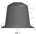
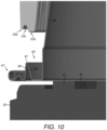
- Figures 7 to 12 illustrate a second embodiment of capsule 1.
- Features corresponding to those of the first embodiment are denoted by corresponding reference signs.
- Features of the first embodiment and this embodiment may be interchanged and combined as desired.
- only differences between the embodiments will be described in detail. In other respects the reader is directed to the description of the prior embodiment.
- the cup-shaped body 40 differs from that of the first embodiment in the configuration and geometry of the annular trough 60.
- the annular trough 60 is dimensioned to receive, partially or wholly, the leading edge 23 of the enclosing member 2 on movement of the enclosing member 2 into the closed position.
- the inner wall 65 of the annular trough 60 is substantially perpendicular to the floor 64.
- the outer wall 66 is angled relative to the floor 64, such that an internal angle ⁇ at a junction between the floor 64 and the outer wall 66 is from 90° to 120°, preferably 105°.
- the ridge zone 63 is again located radially outwards of the annular trough 60 and comprises an annular projection which extends back in the general direction of the base 42 such that an apex 67 of the ridge zone 63 is raised above the level of the floor 64 of the annular trough 60.
- the apex 67 may be raised above the floor 64 by a distance from 0.75 to 2.5 mm. As illustrated in this embodiment, the distance is 2.2 mm.
- the ridge zone 63 may be formed to have an inner wall provided by the angled outer wall 66 of the annular trough 60 and an outer wall 68 formed by at least a portion of the second side wall section 62.
- the second side wall section 62 may comprise between the outer wall 68 and the rolled-over portion 48 of the rim 47 an additional annular ridge 70 which may provide additional stiffness to the outer portion of the flange.
- the height of the additional annular ridge 70 may be 0.7 to 0.8 mm.
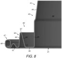
- the side wall 43 including the annular trough 60 and the ridge zone 63 may be formed integrally. Further, the cup-shaped body 40 including the side wall 43 and the base 42 may be formed integrally.
- the annular trough 60 may have an internal width of from 1.3 to 2.0 mm. As illustrated, the annular trough 60 has an internal width of approximately 1.5 mm to 1.8 mm.
- the lid 41 is sealed to the annular trough 60.
- the lid 41 is sealed to an inner surface of the floor 64 of the annular trough 60.
- the floor 64 of the annular trough 60 is substantially level with a distal end of the side wall 43 prior to insertion. As illustrated the offset from the distal end of the side wall 43 and the lid is only 0.2 mm.
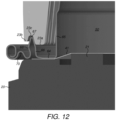
- Figure 9 illustrates that the leading edge 23 of the enclosing member 2 may comprise an inner rim 23a and an outer rim 23b which are concentric and spaced apart from one another to define a recess 23c there between, which may be generally annular (although may have interruptions around its circumference).
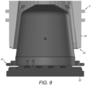
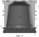
- the side wall 43 of the capsule 1 is contacted by the enclosing member 2 to deform the side wall 43.
- the inner rim 23a of the leading edge 23 is received in the annular trough 60 and bears on the outer wall 66 while at the same time (or shortly thereafter) the apex 67 of the ridge zone 63 is received in the recess 23c.
- the ridge zone 63 (and floor 64) is driven downwards by the action of the enclosing member 2 on the outer wall 66 and/or apex 67 causing the outer wall 66 of the annular trough 60 and the outer wall 68 of the ridge zone 63 to buckle and deform/crumple.
- the material of the outer wall 66 of the annular trough 60 may be plastically drawn over the leading edge 23 to conform the outer wall 66 of the annular trough 60 to the grooves or indentations to provide an effective seal.
- the downward movement of the ridge zone 63 also nips the floor 64 (and the lid 41 sealed to the floor 64) against the capsule holder 20 as shown in Figure 12 .
- the geometry of the outer wall 68 of the ridge zone 63, with the additional annular ridge 70 helps to stiffen the distal end of the side wall 43 and prevent the rim 47 being deflected down into contact with the capsule holder 20.
- Piercing and brewing of a beverage from the capsule 1 may be as described above in the first embodiment.
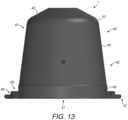
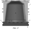
- Figures 13 to 18 illustrate a third embodiment of capsule 1.
- Features corresponding to those of the first and/or second embodiment are denoted by corresponding reference signs.
- Features of the first and/or second embodiment and this embodiment may be interchanged and combined as desired.
- only differences between the embodiments will be described in detail. In other respects the reader is directed to the description of the prior embodiments.
- the cup-shaped body 40 differs from that of the first and second embodiments in the configuration and geometry of the annular trough 60.
- the annular trough 60 is dimensioned to receive, partially or wholly, the leading edge 23 of the enclosing member 2 on movement of the enclosing member 2 into the closed position.
- the inner wall 65 of the annular trough 60 is substantially perpendicular to the floor 64 and the outer wall 66 is angled relative to the floor 64, such that an internal angle ⁇ at a junction between the floor 64 and the outer wall 66 is from 90° to 120°, preferably 105°.
- the ridge zone 63 is again located radially outwards of the annular trough 60 and comprises an annular projection which extends back in the general direction of the base 42 such that an apex 67 of the ridge zone 63 is raised above the level of the floor 64 of the annular trough 60.
- the apex 67 is somewhat more rounded than in the second embodiment.
- the apex 67 may be raised above the floor 64 by a distance from 0.75 to 2.5 mm. As illustrated in this embodiment, the distance is 2.2 mm.
- the ridge zone 63 may be formed to have an inner wall provided by the angled outer wall 66 of the annular trough 60 and an outer wall 68 formed by at least a portion of the second side wall section 62.
- the outer wall 68 comprises three distinct sections - an upper section 73 which, prior to insertion, is perpendicular to the floor 64, a mid-section 71 that is angled at an angle ⁇ of from 20 to 80°, preferably 60°, to the vertical and a lower section 72 that includes a horizontal portion - parallel to the floor 64 - before merging into the rolled-over portion 48 of the rim 47.
- the side wall 43 including the annular trough 60 and the ridge zone 63 may be formed integrally. Further, the cup-shaped body 40 including the side wall 43 and the base 42 may be formed integrally.
- the annular trough 60 may have an internal width of from 1.3 to 2.0 mm. As illustrated, the annular trough 60 has an internal width of approximately 1.5 mm to 1.8 mm.
- the lid 41 is sealed to the annular trough 60.
- the lid 41 is sealed to an inner surface of the floor 64 of the annular trough 60.
- the floor 64 of the annular trough 60 is substantially level with a distal end of the side wall 43 prior to insertion. As illustrated the offset from the distal end of the side wall 43 and the lid is only 0.2 mm.
- the side wall 43 of the capsule 1 is contacted by the enclosing member 2 to deform the side wall 43.
- the inner rim 23a of the leading edge 23 is received in the annular trough 60 and bears on the outer wall 66 while at the same time (or shortly thereafter) the apex 67 of the ridge zone 63 is received in the recess 23c.
- the ridge zone 63 (and floor 64) is driven downwards by the action of the enclosing member 2 on the outer wall 66 and/or apex 67 causing the outer wall 66 of the annular trough 60 and the outer wall 68 of the ridge zone 63 to buckle and deform/crumple.
- the material of the outer wall 66 of the annular trough 60 may be plastically drawn over the leading edge 23 to conform the outer wall 66 of the annular trough 60 to the grooves or indentations to provide an effective seal.
- the downward movement of the ridge zone 63 also nips the floor 64 (and the lid 41 sealed to the floor 64) against the capsule holder 20 as shown in Figure 12 .
- the geometry of the outer wall 68 of the ridge zone 63, with the upper section 73, mid-section 71 and lower section 72 helps to stiffen the distal end of the side wall 43 and prevent the rim 47 being deflected down into contact with the capsule holder 20.
- Piercing and brewing of a beverage from the capsule 1 may be as described above in the first embodiment.
- the capsule 1 of any of the above embodiments may comprise a side wall 43 formed from a laminate material as discussed above having a polymer layer.
- Closure of the enclosing member 2 may compress at least the polymer layer of the laminate material when forming any of the sealing interfaces mentioned above.
- the compression of the polymer layer may aid the conforming of the side wall 43 to the shape of the leading edge 23.
- the polymer layer may aid filling of any gaps arising due to the presence of grooves in the leading edge 23.
- the polymer layer is directed outwardly to be directly contacted by the leading edge 23.
- the cup-shaped body 40 may comprise a unitary piece of laminate material.
- the laminate may comprise a ductile structural layer formed from a material such as aluminium or an aluminium alloy together with a resilient layer formed from a polymer.
- the laminate may comprise only a single layer of aluminium or aluminium alloy together with a single layer of polymer together with one or more optional lacquer layers, tie layers or adhesive layers applied to the aluminium or aluminium alloy.
- the polymer layer may, for example, comprise a material selected from the group of: polyvinyl chloride (PVC), polypropylene (PP), low density polyethylene (LDPE), medium density polyethylene (MDPE), high density polyethylene (HDPE), fluorinated ethylene propylene (FEP), polytetrafluoroethylene (PTFE), polyethylene terephthalate (PET), polyamide (PA), ethylene propylene diene monomer (EPDM), polychloroprene or isobutylene.
- PVC polyvinyl chloride
- PP polypropylene
- LDPE low density polyethylene
- MDPE medium density polyethylene
- HDPE high density polyethylene
- FEP fluorinated ethylene propylene
- PTFE polytetrafluoroethylene
- PET polyethylene terephthalate
- PA ethylene propylene diene monomer
- EPDM ethylene propylene diene monomer
- the hot water passed through the receptacle 3 may act to slightly soften the material of the polymer layer. Such softening may lead to further deformation of the side wall 43 under the compressive loading of the enclosing member 2. This effect may help to reinforce the fluid seal between the enclosing member 2 and the capsule 1 by tending to seal up any gaps having hot water leaking there through.
- the deformation of the side wall 43 will also typically cause a reduction in the longitudinal height of the capsule 1 relative to its height prior to insertion.
Abstract
- an annular trough being dimensioned to receive an enclosing member of the beverage preparation machine on movement of the enclosing member into a closed position;
- a first side wall section extending between the base and the annular trough; and
- a second side wall section extending between the annular trough and a rim of the capsule.
Description
- The present disclosure relates to a beverage preparation system, a capsule and a method for forming a beverage. The beverage preparation system is of the type comprising a beverage preparation machine wherein the capsule is designed for insertion into the beverage preparation machine to permit a pressurised liquid to be flowed through the capsule in order to produce a beverage from interaction with beverage ingredients contained within the capsule.
- Beverage preparation systems which comprise a beverage preparation machine and a capsule containing beverage ingredients are known in the art. One such system is taught in
EP 1700548 , which discloses a capsule comprising a cup-like base body and a closing foil member. The capsule is designed for insertion in a beverage production device in which a liquid under pressure enters the capsule in order to interact with ingredients in the capsule to form a beverage which is output for consumption. The capsule ofEP 1700548 is provided with a dedicated sealing member to prevent a bypass flow of water around the exterior of the capsule in use. The sealing member is in the form of a hollow sealing member on the outer surface of the capsule, for example in the form of a step which is contacted on closure of an enclosing member of the beverage preparation machine. - The present disclosure provides an alternative capsule which may be used as part of such a beverage preparation system. The capsule may be economical to produce and provide effective sealing in use.
- In a first aspect the present disclosure provides a beverage producing system comprising:
- a capsule containing beverage ingredients; and
- a beverage preparation machine;
- the capsule comprising a cup-shaped body and a lid; the cup-shaped body having a base and a side wall and the lid being sealed to the cup-shaped body;
- the capsule being designed for insertion into the beverage preparation machine to permit a pressurised liquid to be flowed through the capsule in order to produce a beverage from interaction with the beverage ingredients;
- the beverage preparation machine having an enclosing member adapted to be selectively movable between an open position to permit insertion of the capsule into the beverage preparation machine and a closed position in which the enclosing member sealingly engages the capsule;
- wherein, prior to insertion, the side wall comprises:
- an annular trough being dimensioned to receive the enclosing member on movement of the enclosing member into the closed position;
- a first side wall section extending between the base and the annular trough; and
- a second side wall section extending between the annular trough and a rim of the capsule.
- In a second aspect, the present disclosure provides a capsule for preparing a beverage comprising a cup-shaped body and a lid; the cup-shaped body having a base and a side wall and the lid being sealed to the cup-shaped body;
- the capsule being designed for insertion into a beverage preparation machine to permit a pressurised liquid to be flowed through the capsule in order to produce a beverage from interaction with the beverage ingredients;
- the beverage preparation machine being of the type having an enclosing member adapted to be selectively movable between an open position to permit insertion of the capsule into the beverage preparation machine and a closed position in which the enclosing member sealingly engages the capsule;
- wherein the side wall comprises:
- an annular trough being dimensioned to receive the enclosing member;
- a first side wall section extending between the base and the annular trough; and
- a second side wall section extending between the annular trough and a rim of the capsule.
- In a third aspect the present disclosure provides a method for preparing a beverage comprising the steps of:
- providing a capsule as described above;
- providing a beverage preparation machine having an enclosing member;
- moving the enclosing member into an open position;
- inserting the capsule into the beverage preparation machine;
- closing the enclosing member so as to sealingly engage the enclosing member with the capsule;
- flowing a pressurised liquid through the capsule to produce a beverage from interaction with the beverage ingredients; and
- outputting the beverage for consumption;
- The above aspects may further comprise one or more of the following features:
- The annular trough may be dimensioned to partially or wholly receive a leading edge of the enclosing member therein on movement of the enclosing member into the closed position.
- The second side wall section may define a ridge zone located radially outwards of the annular trough.
- The side wall may be adapted to undergo plastic deformation during closure of the enclosing member.
- The side wall may be adapted such that, in use, closure of the enclosing member deforms the side wall to cause the second side wall section to be forced inwardly against an outer face of the enclosing member to form a sealing interface with the outer face of the enclosing member.
- The annular trough may be adapted to form a sealing interface with a leading edge of the enclosing member.
- Advantageously, a sealing interface may be provided with both the leading edge and the outer face of the enclosing member. In addition, the deformation of the annular trough may also cause an outward pressure to be exerted by the side wall on the inner face of the enclosing member to form a further sealing interface.
- The side wall may be adapted such that during closure of the enclosing member the side wall is plastically drawn over the leading edge of the enclosing member. Advantageously this may allow the side wall to be conformed to the shape of any grooves (or similar) provided in the leading edge.
- Prior to insertion, the annular trough may comprise an inner wall, an outer wall and a floor. On closure of the enclosing member a leading edge of the enclosing member may contact the outer wall of the annular trough and form a seal therewith.
- The inner wall and outer wall may be substantially perpendicular to the floor. In an alternative arrangement the outer wall may be angled relative to the floor, such that an internal angle at a junction between the floor and the outer wall is from 90° to 120°, preferably 105°. Thus the seal with the enclosing member may be a tapered seal.
- The ridge zone may comprise an apex, and a leading edge of the enclosing member may comprise an inner rim and an outer rim and a recess located between the inner rim and the outer rim, wherein on closure of the enclosing member the apex of the ridge zone may be received in the recess between the inner rim and the outer rim.
- The annular trough may be adapted to be nipped against a capsule holder of the beverage preparation machine part.
- Prior to insertion, a floor of the annular trough may be raised relative to the rim. The floor of the annular trough may be offset from a distal end of the side wall by a distance from 0.1 to 2.0 mm. In one example, the offset may be relatively large, for example it may be from 1.55 to 2.0 mm. In a specific example the offset may be 1.85 mm. Where the offset is relatively large, the floor of the annular trough may be from 0.75 to 1.2 mm below an apex of the ridge zone (where present). In one example, the distance may be 0.9 mm. In another example, prior to insertion, the floor of the annular trough may be substantially level with the rim. For example the offset may be 0.1 to 0.5 mm. In one example the offset may be 0.2 mm. In this alternative arrangement the floor of the annular trough may be from 2.0 to 2.5 mm below an apex of the ridge zone (where present). In one example, the distance is 2.2 mm.
- The side wall may be adapted such that, in use, closure of the enclosing member deforms the side wall to cause the floor of the annular trough to be brought substantially into alignment with the rim.
- The first side wall section, annular trough and second side wall section may be formed integrally.
- The rim may be formed integrally with the cup-shaped body.
- The rim may be formed by a rolled-over portion of the side wall.
- Prior to insertion, the side wall may comprise a frustoconical section proximate the base.
- Prior to insertion, the side wall may comprise a cylindrical section between the frustoconical section and the annular trough.
- The annular trough may have an internal width of from 1.3 to 2.0 mm. In one example, the annular trough has an internal width of approximately 1.5 mm to 1.8 mm.
- The annular trough may have an internal diameter of from 27.5 to 30.0 mm and an outer diameter of from 29.3 to 32.5 mm.
- The lid may be sealed to the annular trough of the side wall. The lid may be sealed to an inner surface of a floor of the annular trough.
- A leading edge of the enclosing member may comprise a plurality of grooves or indentations, and the side wall may be adapted such that the plastic deformation of the side wall conforms the annular trough of the side wall to the grooves or indentations to provide an effective seal. In one arrangement the plastic deformation of the side wall conforms the outer wall of the annular trough to the grooves or indentations to provide an effective seal.
- At least a portion of the cup-shaped body, preferably a whole of the cup-shaped body, may be formed from aluminium, an aluminium alloy or a laminate comprising at least one layer formed from aluminium or an aluminium alloy. A lacquer layer may be applied to one or both faces of the cup-shaped body. Alternatively, another, suitably ductile material could be utilised in place of the aluminium or aluminium alloy.
- The aluminium alloy may, for example, be of grade 3005, 3105, 8011 or 8079. Preferably, the aluminium alloy will have an 'O' temper rating.
- The laminate, where used, may comprise a ductile structural layer formed from a material such as aluminium or an aluminium alloy together with a resilient layer formed from a polymer. The laminate may comprise only a single layer of aluminium or aluminium alloy together with a single layer of polymer together with one or more optional lacquer layers, tie layers or adhesive layers applied to the aluminium or aluminium alloy.
- The cup-shaped body may comprise a unitary piece of laminate material.
- The polymer layer may, for example, comprise a material selected from the group of: polyvinyl chloride (PVC), polypropylene (PP), low density polyethylene (LDPE), medium density polyethylene (MDPE), high density polyethylene (HDPE), fluorinated ethylene propylene (FEP), polytetrafluoroethylene (PTFE), polyethylene terephthalate (PET), polyamide (PA), ethylene propylene diene monomer (EPDM), polychloroprene or isobutylene.
- The polymer of the polymer layer preferably has a hardness of less than or equal to 40 D Shore Hardness. Advantageously, using a relatively soft polymer for the outer layer of the laminate allows the material to deform around imperfections and features of the enclosing member to provide a more effective hydraulic seal.
- The lid may be formed from aluminium, an aluminium alloy or a laminate comprising at least one layer formed from aluminium or an aluminium alloy. Alternatively, another, suitably ductile material could be utilised. The lid may further comprise a heat seal lacquer or heat seal layer to enhance sealing of the lid to the cup-shaped body.
- The cup-shaped body may be formed from a single integral piece of material. The single piece of material may be cold drawn to form the shape of the cup-shaped body, including the annular trough. A deep-drawing technique may be used to cold form the cup-shaped body. Where the material of the cup-shaped body comprises a laminate with a polymer layer, a warm-drawing technique may be used where the material is subjected to an increased temperature to promote easier deformation of the polymer material but without detrimental effects on the material characteristics of the aluminium layer.
- The cup-shaped body and rim may be integral.
- The cup-shaped body may have a thickness in the range of 80 to 500 microns. In some aspects the thickness may be in the range of 90 to 300 microns. Where the cup-shaped body is formed solely from aluminium or an aluminium alloy (optionally with one or more lacquer layers) a thickness in the range of 80 to 120 microns may be preferred. Where the cup-shaped body is formed from a laminate material comprising a polymer layer a thickness in the range 100 to 500 microns is preferred. The thickness of the material may be varied throughout the cup-shaped body.
- The rim may have an outer diameter of approximately 37 mm.
- Prior to insertion, the capsule may have a height of from 25 to 31 mm. In some aspects the height may be from 28.5 to 30 mm. Deformation of the capsule during use will tend to reduce the longitudinal height.
- Preferably, the cup-shaped bodies may be shaped in a way that can be stacked and destacked easily prior to filling and assembly with the lids.
- The capsule may form a single-use, disposable element.
- The capsule may contain a beverage ingredient or mixture of beverage ingredients. As a non-limiting example, the beverage ingredient may comprise roasted ground coffee.
- Further aspects of the invention are set out in the following numbered clauses:
- 1. A beverage producing system comprising:
- a capsule containing beverage ingredients; and
- a beverage preparation machine;
- the capsule comprising a cup-shaped body and a lid; the cup-shaped body having a base and a side wall and the lid being sealed to the cup-shaped body;
- the capsule being designed for insertion into the beverage preparation machine to permit a pressurised liquid to be flowed through the capsule in order to produce a beverage from interaction with the beverage ingredients;
- the beverage preparation machine having an enclosing member adapted to be selectively movable between an open position to permit insertion of the capsule into the beverage preparation machine and a closed position in which the enclosing member sealingly engages the capsule;
- wherein, prior to insertion, the side wall comprises:
- an annular trough being dimensioned to receive the enclosing member on movement of the enclosing member into the closed position;
- a first side wall section extending between the base and the annular trough; and
- a second side wall section extending between the annular trough and a rim of the capsule.
- 2. A beverage producing system as in
clause 1, wherein the second side wall section defines a ridge zone located radially outwards of the annular trough. - 3. A beverage producing system as in
clause 1 orclause 2, wherein the side wall is adapted to undergo plastic deformation during closure of the enclosing member. - 4. A beverage producing system as in any preceding clause, wherein the side wall is adapted such that, in use, closure of the enclosing member deforms the side wall to cause the second side wall section to be forced inwardly against an outer face of the enclosing member to form a sealing interface with the outer face of the enclosing member.
- 5. A beverage producing system as in any preceding clause, wherein the annular trough is adapted to form a sealing interface with a leading edge of the enclosing member.
- 6. A beverage producing system as in clause 5, wherein the side wall is adapted such that during closure of the enclosing member the side wall is plastically drawn over the leading edge of the enclosing member.
- 7. A beverage producing system as in any preceding clause, wherein, prior to insertion, the annular trough comprises an inner wall, an outer wall and a floor.
- 8. A beverage producing system as in
clause 7, wherein on closure of the enclosing member a leading edge of the enclosing member contacts the outer wall of the annular trough and forms a seal therewith. - 9. A beverage producing system as in
clause 7 or clause 8, wherein the inner wall and outer wall are substantially perpendicular to the floor. - 10. A beverage producing system as in
clause 7 or clause 8, wherein the outer wall is angled relative to the floor, such that an internal angle at a junction between the floor and the outer wall is from 90° to 120°, preferably 105°. - 11. A beverage producing system as in any of
clauses 3 to 10, as dependent onclause 2, wherein the ridge zone comprises an apex, and a leading edge of the enclosing member comprises an inner rim and an outer rim and a recess located between the inner rim and the outer rim, wherein on closure of the enclosing member the apex of the ridge zone is received in the recess between the inner rim and the outer rim. - 12. A beverage producing system as in any preceding clause, wherein the annular trough is adapted to be nipped against a capsule holder of the beverage preparation machine part.
- 13. A beverage producing system as in any preceding clause, wherein, prior to insertion, a floor of the annular trough is raised relative to the rim.
- 14. A beverage producing system as in clause 13, wherein the side wall is adapted such that, in use, closure of the enclosing member deforms the side wall to cause the floor of the annular trough to be brought substantially into alignment with the rim.
- 15. A beverage producing system as in any of
clauses 1 to 12, wherein, prior to insertion, a floor of the annular trough is substantially level with the rim. - 16. A beverage producing system as in any preceding clause, wherein the first side wall section, annular trough and second side wall section are formed integrally.
- 17. A beverage producing system as in any preceding clause, wherein the rim is formed integrally with the cup-shaped body.
- 18. A beverage producing system as in clause 17, wherein the rim is formed by a rolled-over portion of the side wall.
- 19. A beverage producing system as in any preceding clause, wherein, prior to insertion, the side wall comprises a frustoconical section proximate the base.
- 20. A beverage producing system as in clause 19, wherein, prior to insertion, the side wall comprises a cylindrical section between the frustoconical section and the annular trough.
- 21. A beverage producing system as in any preceding clause, wherein the annular trough has an internal width of from 1.3 to 2.0 mm.
- 22. A beverage producing system as in any preceding clause, wherein the annular trough has an internal width of approximately 1.5 mm to 1.8 mm.
- 23. A beverage producing system as in any preceding clause, wherein the annular trough has an internal diameter of from 27.5 to 30.0 mm and an outer diameter of from 29.3 to 32.5 mm.
- 24. A beverage producing system as in any preceding clause, wherein the lid is sealed to the annular trough of the side wall.
- 25. A beverage producing system as in
clause 24, wherein the lid is sealed to an inner surface of a floor of the annular trough. - 26. A beverage producing system as in any preceding clause, wherein a leading edge of the enclosing member comprises a plurality of grooves or indentations, and the side wall is adapted such that the plastic deformation of the side wall conforms the annular trough of the side wall to the grooves or indentations to provide an effective seal.
- 27. A beverage producing system as in clause 26, wherein the plastic deformation of the side wall conforms the outer wall of the annular trough to the grooves or indentations to provide an effective seal.
- 28. A capsule for preparing a beverage comprising a cup-shaped body and a lid; the cup-shaped body having a base and a side wall and the lid being sealed to the cup-shaped body;
- the capsule being designed for insertion into a beverage preparation machine to permit a pressurised liquid to be flowed through the capsule in order to produce a beverage from interaction with the beverage ingredients;
- the beverage preparation machine being of the type having an enclosing member adapted to be selectively movable between an open position to permit insertion of the capsule into the beverage preparation machine and a closed position in which the enclosing member sealingly engages the capsule;
- wherein the side wall comprises:
- an annular trough being dimensioned to receive the enclosing member;
- a first side wall section extending between the base and the annular trough; and
- a second side wall section extending between the annular trough and a rim of the capsule.
- 29. A capsule as in clause 28, the second side wall section defines a ridge zone located radially outwards of the annular trough.
- 30. A capsule as in clause 28 or clause 29, wherein the side wall is adapted to undergo plastic deformation during closure of the enclosing member.
- 31. A capsule as in any of clauses 28 to 30, wherein a floor of the annular trough is raised relative to the rim.
- 32. A capsule as in any of clauses 28 to 30, wherein a floor of the annular trough is substantially level with the rim.
- 33. A capsule as in any of clauses 28 to 32, wherein the first side wall section, annular trough and second side wall section are formed integrally.
- 34. A capsule as in any of clauses 28 to 33, wherein the annular trough comprises an inner wall, an outer wall and a floor.
- 35. A capsule as in clause 34, wherein the inner wall and outer wall are substantially perpendicular to the floor.
- 36. A capsule as in clause 34, wherein the outer wall is angled relative to the floor, such that an internal angle at a junction between the floor and the outer wall is from 90° to 120°, preferably 105°.
- 37. A capsule as in any of clauses 28 to 36, wherein the rim is formed integrally with the cup-shaped body.
- 38. A capsule as in any of clauses 28 to 37, wherein the rim is formed by a rolled-over portion of the side wall.
- 39. A capsule as in any of clauses 28 to 38, wherein the side wall comprises a frustoconical section proximate the base.
- 40. A capsule as in
clause 39, wherein the side wall comprises a cylindrical section between the frustoconical section and the annular trough. - 41. A capsule as in any of clauses 28 to 40, wherein the annular trough has an internal width of from 1.3 to 2.0 mm.
- 42. A capsule as in any of clauses 28 to 41, wherein the annular trough has an internal width of approximately 1.5 mm to 1.8 mm.
- 43. A capsule as in any of clauses 28 to 42, wherein the annular trough has an internal diameter of from 27.5 to 30.0 mm and an outer diameter of from 29.3 to 32.5 mm.
- 44. A capsule as in any of clauses 28 to 43, wherein the lid is sealed to the annular trough of the side wall.
- 45. A capsule as in
clause 44, wherein the lid is sealed to an inner surface of a floor of the annular trough. - 46. A capsule as in any of clauses 28 to 45, wherein at least a portion of the cup-shaped body, preferably a whole of the cup-shaped body, is formed from aluminium, an aluminium alloy or a laminate comprising at least one layer formed from aluminium or an aluminium alloy.
- 47. A capsule as in clause 46, wherein the laminate comprises at least an aluminium or aluminium alloy layer and a polymer layer.
- 48. A capsule as in
clause 47, wherein the cup-shaped body comprises a unitary piece of laminate material. - 49. A capsule as in
clause - 50. A capsule as in any of
clauses 47 to 49, wherein the polymer layer comprises a material selected from the group of: polyvinyl chloride (PVC), polypropylene (PP), low density polyethylene (LDPE), medium density polyethylene (MDPE), high density polyethylene (HDPE), fluorinated ethylene propylene (FEP), polytetrafluoroethylene (PTFE), polyethylene terephthalate (PET), polyamide (PA), ethylene propylene diene monomer (EPDM), polychloroprene or isobutylene. - 51. A capsule as in any of clauses 28 to 50, wherein the lid is formed from aluminium, an aluminium alloy or a laminate comprising at least one layer formed from aluminium or an aluminium alloy.
- 52. A capsule as in any of clauses 28 to 51, wherein the cup-shaped body has a thickness in the range of 80 to 500 microns.
- 53. A method for preparing a beverage comprising the steps of:
- providing a capsule as in any of clauses 28 to 52;
- providing a beverage preparation machine having an enclosing member;
- moving the enclosing member into an open position;
- inserting the capsule into the beverage preparation machine;
- closing the enclosing member so as to sealingly engage the enclosing member with the capsule;
- flowing a pressurised liquid through the capsule to produce a beverage from interaction with the beverage ingredients; and
- outputting the beverage for consumption;
- wherein on closure, the enclosing member engages the annular trough of the side wall of the capsule to thereby deform the side wall;
- wherein said deformation of the side wall causes the formation of at least one sealing interface between the enclosing member and the side wall.
- 54. The method of clause 53 wherein the side wall undergoes plastic deformation during closure of the engaging member.
- 55. The method of clause 53 or clause 54, wherein deformation of the annular trough forms a sealing interface with a leading edge of the enclosing member.
- 56. The method of clause 55, wherein the side wall is plastically drawn over the leading edge of the enclosing member.
- 57. The method of any of clauses 53 to 56, wherein the annular trough is nipped against a capsule holder of the beverage preparation machine part.
- 58. The method of any of clauses 53 to 57, wherein the second side wall section is forced inwardly against an outer face of the enclosing member to form a sealing interface with the outer face of the enclosing member.
- 59. The method of any of clauses 53 to 58, wherein on closure of the enclosing member a leading edge of the enclosing member contacts the outer wall of the annular trough and forms a seal therewith.
- 60. The method of any of clauses 53 to 59, wherein the ridge zone comprises an apex, and a leading edge of the enclosing member comprises an inner rim and an outer rim and a recess located between the inner rim and the outer rim, wherein on closure of the enclosing member the apex of the ridge zone is received in the recess between the inner rim and the outer rim.
- 61. The method of any of clauses 53 to 60, wherein closure of the enclosing member deforms the side wall to cause the floor of the annular trough to be brought substantially into alignment with the rim.
- 62. The method of any of clauses 53 to 61, wherein a leading edge of the enclosing member comprises a plurality of grooves or indentations, and the side wall is plastically deformed to conform the side wall to the grooves or indentations to provide an effective seal.
- Examples of the present disclosure will now be described in more detail, for exemplary purposes only, with reference to the accompanying drawings, in which:
-
Figure 1 is a cross-sectional view of a first embodiment of capsule according to the present disclosure; -
Figure 2 is an enlarged view of a detail ofFigure 1 ; -
Figure 3 is a schematic illustration of the capsule ofFigure 1 together with an enclosing member of a beverage preparation machine; -
Figure 4 is an enlarged view of a detail ofFigure 3 ; -
Figure 5 is a schematic illustration of the arrangement ofFigure 3 with the enclosing member in a closed position; -
Figure 6 is an enlarged view of a detail ofFigure 5 ; -
Figure 7 is a cross-sectional view of a second embodiment of capsule according to the present disclosure; -
Figure 8 is an enlarged view of a detail ofFigure 7 ; -
Figure 9 is a schematic illustration of the capsule ofFigure 7 together with an enclosing member of a beverage preparation machine; -
Figure 10 is an enlarged view of a detail ofFigure 9 ; -
Figure 11 is a schematic illustration of the arrangement ofFigure 9 with the enclosing member in a closed position; -
Figure 12 is an enlarged view of a detail ofFigure 11 ; -
Figure 13 is a cross-sectional view of a third embodiment of capsule according to the present disclosure; -
Figure 14 is an enlarged view of a detail ofFigure 13 ; -
Figure 15 is a schematic illustration of the capsule ofFigure 13 together with an enclosing member of a beverage preparation machine; -
Figure 16 is an enlarged view of a detail ofFigure 15 ; -
Figure 17 is a schematic illustration of the arrangement ofFigure 15 with the enclosing member in a closed position; and -
Figure 18 is an enlarged view of a detail ofFigure 17 . -
Figure 3 shows schematically a part of a beverage preparation system according to the present disclosure. The beverage preparation system comprises a beverage preparation machine and acapsule 1. -
Figures 1 and2 show a first embodiment ofcapsule 1. Thecapsule 1 will be described in more detail below but may have the general form of a cup-shapedbody 40 having a base 42 at one end and aside wall 43 extending from the base 42 towards an opposed end which is closed-off by alid 41. - As shown in
Figure 3 , the beverage preparation machine comprises an enclosingmember 2 and acapsule holder 20. The enclosingmember 2 is selectively movable relative to acapsule holder 20 between an open position, to permit insertion of thecapsule 1 into the beverage preparation machine, and a closed position, in which the enclosingmember 2 sealingly engages thecapsule 1 against thecapsule holder 20 in a manner that will be described below. - The enclosing
member 2 may be moved between the open and closed positions by means of a conventional mechanism well known in the art. For example, the means may involve a mechanical mechanism activated by a manually-movable lever or an automatic or semi-automatic mechanism where movement is driven by a motor. The enclosingmember 2 may be moved while thecapsule holder 20 remains stationary. Alternatively, the enclosingmember 2 may remain stationary and thecapsule holder 20 be moved. In a further alternative arrangement, both the enclosingmember 2 and thecapsule holder 20 may move during the opening and closing operations. - The enclosing
member 2 and thecapsule holder 20 in the closed position together define areceptacle 3 for holding thecapsule 1 during a dispensing operation. - The beverage preparation machine may further comprise other conventional elements which are not illustrated in the accompanying drawings and are well known in the art of beverage preparation machines. For example, the beverage preparation machine may comprise either a facility for storing an aqueous medium, such as an internal reservoir, or a facility for connection to an external supply of aqueous medium, such as mains water. The aqueous medium will typically be water. A pump or equivalent may be provided for supplying the aqueous medium in a pressurised state to the
capsule 1. The aqueous medium will typically be supplied at a pressure of up to 9 to 14 bar. A heater may be provided for heating the aqueous medium to a desired temperature. The heater may heat the aqueous medium in the reservoir (where present) or may heat the aqueous medium on-demand as it passes through a conduit or over a thermoblock to thereceptacle 3. The beverage preparation machine may comprise base piercing means for piercing thebase 42 of thecapsule 1 to permit the aqueous medium to enter thecapsule 1 and interact with the beverage ingredients therein. Alternatively, thecapsule 1 may be provided with one or more pre-formed openings to allow entry of the aqueous medium from thereceptacle 3 into thecapsule 1. - The enclosing
member 2 may be of the type described inEP 1700548 comprising anannular element 22 having a leadingedge 23 in the form of an annular rim, aninner face 25 facing thereceptacle 3 and anouter face 24 facing an exterior. The leadingedge 23 may be provided with a plurality of grooves as taught inEP 1700548 . An upper end (not shown) of the enclosingmember 2 may be coupled to a supply of the aqueous medium and may provide a mounting for one or more perforation elements intended to pierce thebase 42 of thecapsule 1 in use. - The
capsule holder 20 may be of the type described inEP 1700548 comprisingrelief elements 21 which are designed to tear and perforate thelid 41 of thecapsule 1. The tearing of thelid 41 may occur due to internal pressurisation of thecapsule 1 caused by inflowing aqueous medium. Therelief elements 21 may have any protruding shape able to cause a partial tearing of the foil member, e.g. pyramids, needles, bumps, cylinders, or elongated ribs. - As shown in
Figure 1 , the cup-shapedbody 40 and thelid 41 of thecapsule 1 together enclose abeverage ingredient chamber 50 which may be filled with a beverage ingredient or mixture of beverage ingredients. As a non-limiting example, the beverage ingredient may comprise roasted ground coffee. - In the illustrated example, the cup-shaped
body 40 is made from aluminium or an aluminium alloy. However, other materials may be utilised, such as a laminate of aluminium or aluminium alloy and a polymer. The cup-shapedbody 40 includes thebase 42 and theside wall 43. There may be, as illustrated, a geometric discontinuity at the junction between the base 42 and theside wall 43, for example, in the form of ashoulder 57. Alternatively, thebase 42 and theside wall 43 may have a smooth geometric transition. - The cup-shaped
body 40 may have a thickness in the range of 80 to 500 microns. The thickness of the material may be varied throughout the cup-shapedbody 40. In the illustrated example the thickness is 100 microns. - The
side wall 43 is provided with anannular trough 60 which is dimensioned to receive, partially or wholly, the leadingedge 23 of the enclosingmember 2 on movement of the enclosingmember 2 into the closed position. A firstside wall section 61 is provided extending between the base 42 and theannular trough 60 and a secondside wall section 62 is provided extending between theannular trough 60 and a distal end of theside wall 43 of thecapsule 1. - The
annular trough 60 may be defined by aninner wall 65, anouter wall 66 and afloor 64 which extends there between. Theinner wall 65 andouter wall 66 may, prior to insertion of thecapsule 1 in the beverage preparation machine, extend perpendicularly to thefloor 64. Theinner wall 65 may be formed by a portion of the firstside wall section 61. - A
ridge zone 63 is located radially outwards of theannular trough 60. Theridge zone 63 may comprise an annular projection which extends back in the general direction of the base 42 such that an apex 67 of theridge zone 63 is raised above the level of thefloor 64 of theannular trough 60. The apex 67 may be raised above thefloor 64 by a distance from 0.75 to 2.5 mm. As illustrated in this embodiment, the distance is 0.9 mm. Theridge zone 63 may be formed to have an inner wall provided by theouter wall 66 of theannular trough 60 and anouter wall 68 formed by at least a portion of the secondside wall section 62. - The
side wall 43, including theannular trough 60 and theridge zone 63 may be formed integrally. Further, the cup-shapedbody 40 including theside wall 43 and the base 42 may be formed integrally. - The
annular trough 60 may have an internal width of from 1.3 to 2.0 mm. Typically, the internal width of theannular trough 60 is chosen to be marginally greater than the breadth of the leadingedge 23 of theannular element 22. In one example, theannular trough 60 has an internal width of approximately 1.5 mm to 1.8 mm. - The
annular trough 60 may have an internal diameter of from 27.5 to 30.0 mm (that is the diameter of the surface of theinner wall 65 facing into the annular trough 60) and an outer diameter of from 29.3 to 32.5 mm (that is the diameter of the surface of theouter wall 66 facing into the annular trough 60). Optionally, the internal diameter may be chosen so there is a slight interference fit between theinner wall 65 and theouter face 24 of the enclosingmember 2 on closure. This helps to ensure good alignment of theannular trough 60 with the enclosingmember 2. - As illustrated, the
lid 41 is sealed to theannular trough 60. In particular, thelid 41 is sealed to an inner surface of thefloor 64 of theannular trough 60. Thefloor 64 of theannular trough 60 is raised relative to a distal end of theside wall 43. Consequently, thelid 41 is also raised relative to the distal end of theside wall 43. Thefloor 64 may be offset from the distal end of theside wall 43 by a distance from 0.1 to 2.0 mm as described previously. As illustrated, the offset is 1.85 mm. Sealing thelid 41 to thefloor 64 helps to ensure that the enclosingmember 2 does not bear down on a hollow part of thecapsule 1 so as to trap beverage ingredients in between theleading edge 23 and thecapsule holder 20 which could have a detrimental effect on the fluid-tightness of the seal. - The
lid 41 may be formed from aluminium, an aluminium alloy or a laminate containing aluminium. - The first
side wall section 61 may comprise afrustoconical section 44 proximate thebase 42 and acylindrical section 45 distal thebase 42, wherein a portion of thecylindrical section 45 forms theinner wall 65 of theannular trough 60. - The
capsule 1 may be provided with arim 47 formed at an end of the cup-shapedbody 40 remote from thebase 42, i.e. at the distal end of theside wall 43. Therim 47 may be formed integrally with the cup-shapedbody 40. In the illustrated example, therim 47 is formed by a rolled-overportion 48 of theside wall 43. - In use of the beverage preparation system the enclosing
member 2 is first moved into the open position and thecapsule 1 is inserted into a location in between thecapsule holder 20 and the enclosingmember 2. Depending on the design of the beverage preparation machine, thecapsule 1 may be inserted by gravity or by manual placement or a combination thereof. In addition, the initial insertion may place thecapsule 1 in proximity to the enclosingmember 2 such that subsequent movement of the enclosingmember 2 carries thecapsule 1 therewith into engagement with thecapsule holder 20. Alternatively, initial insertion may place thecapsule 1 in proximity to thecapsule holder 20 such that thecapsule 1 remains substantially stationary during closure of the enclosingmember 2. - The enclosing
member 2 is then closed so as to sealingly engage the enclosingmember 2 with thecapsule 1. During this step thebase 42 of thecapsule 1 may be pierced by the perforation elements of the enclosingmember 2. - Pressurised aqueous medium (which may be heated, at ambient temperature or chilled) is then flowed into the
capsule 1 to produce a beverage from interaction with the beverage ingredients. During this step internal pressurisation of thebeverage ingredient chamber 50 causes thelid 41 to be deformed outwardly against therelief elements 21 of thecapsule holder 20 resulting in at least partial tearing of thelid 41 which opens up an exit path from thecapsule 1 for the beverage. - The beverage is then output for consumption.
- As shown in
Figures 5 and 6 , during the step of closing the enclosingmember 2 relative to thecapsule holder 20 theside wall 43 of thecapsule 1 is contacted by the enclosingmember 2 to deform theside wall 43. In particular, the leadingedge 23 enters theannular trough 60 and bears on thefloor 64 and/or theinner wall 65 and/or theouter wall 66. Thefloor 64 is driven downwards by the action of the enclosingmember 2 to nip the floor 64 (and thelid 41 sealed to the floor 64) against thecapsule holder 20. The leadingedge 23 may also act to pinch the material of theside wall 43 during this movement which consequently causes theridge zone 63 to be pivoted inwards to bring the apex 67 of theridge zone 63 and/or theouter wall 66 of theannular trough 60 into sealing engagement with theouter face 24 of theannular element 22 as shown inFigure 6 . Importantly, the initial point of contact between theleading edge 23 and thefloor 64 is axially spaced from thecapsule holder 20 such that there is room for theside wall 43 to deform downwards towards thecapsule holder 20 enough to allow for inward pivoting of theridge zone 63 before theside wall 43 is nipped against thecapsule holder 20. - The induced movement of the
side wall 43 causes theside wall 43 to undergo plastic deformation. In particular, as theside wall 43 is deformed downwards, the side wall 43 (in particular portions of the annular trough 60) may be plastically drawn over the leadingedge 23 of the enclosingmember 2 which encourages the material of theside wall 43 to be closely conformed to the grooves of the leadingedge 23. Thus, theannular trough 60 may form a sealing interface with the leadingedge 23 of the enclosingmember 2. - Further, deformation of the
annular trough 60 may also cause an outward pressure to be exerted by theside wall 43 on theinner face 25 of the enclosingmember 2 to form a further sealing interface. -
Figures 7 to 12 illustrate a second embodiment ofcapsule 1. Features corresponding to those of the first embodiment are denoted by corresponding reference signs. Features of the first embodiment and this embodiment may be interchanged and combined as desired. In addition, in the following description only differences between the embodiments will be described in detail. In other respects the reader is directed to the description of the prior embodiment. - The cup-shaped
body 40 differs from that of the first embodiment in the configuration and geometry of theannular trough 60. As in the first embodiment, theannular trough 60 is dimensioned to receive, partially or wholly, the leadingedge 23 of the enclosingmember 2 on movement of the enclosingmember 2 into the closed position. Theinner wall 65 of theannular trough 60, as before, is substantially perpendicular to thefloor 64. However, in contrast, theouter wall 66 is angled relative to thefloor 64, such that an internal angle α at a junction between thefloor 64 and theouter wall 66 is from 90° to 120°, preferably 105°. - The
ridge zone 63 is again located radially outwards of theannular trough 60 and comprises an annular projection which extends back in the general direction of the base 42 such that an apex 67 of theridge zone 63 is raised above the level of thefloor 64 of theannular trough 60. The apex 67 may be raised above thefloor 64 by a distance from 0.75 to 2.5 mm. As illustrated in this embodiment, the distance is 2.2 mm. Theridge zone 63 may be formed to have an inner wall provided by the angledouter wall 66 of theannular trough 60 and anouter wall 68 formed by at least a portion of the secondside wall section 62. As shown most clearly inFigure 8 , the secondside wall section 62 may comprise between theouter wall 68 and the rolled-overportion 48 of therim 47 an additionalannular ridge 70 which may provide additional stiffness to the outer portion of the flange. The height of the additionalannular ridge 70 may be 0.7 to 0.8 mm. - The
side wall 43, including theannular trough 60 and theridge zone 63 may be formed integrally. Further, the cup-shapedbody 40 including theside wall 43 and the base 42 may be formed integrally. - The
annular trough 60 may have an internal width of from 1.3 to 2.0 mm. As illustrated, theannular trough 60 has an internal width of approximately 1.5 mm to 1.8 mm. - As illustrated, the
lid 41 is sealed to theannular trough 60. In particular, thelid 41 is sealed to an inner surface of thefloor 64 of theannular trough 60. Thefloor 64 of theannular trough 60 is substantially level with a distal end of theside wall 43 prior to insertion. As illustrated the offset from the distal end of theside wall 43 and the lid is only 0.2 mm. - In use of the beverage preparation system, as shown in
Figures 9 to 12 , as before the enclosingmember 2 is first moved into the open position and thecapsule 1 is inserted into a location in between thecapsule holder 20 and the enclosingmember 2.Figure 9 illustrates that the leadingedge 23 of the enclosingmember 2 may comprise aninner rim 23a and anouter rim 23b which are concentric and spaced apart from one another to define arecess 23c there between, which may be generally annular (although may have interruptions around its circumference). - As shown in
Figures 11 and12 , on closing the enclosingmember 2 relative to thecapsule holder 20 theside wall 43 of thecapsule 1 is contacted by the enclosingmember 2 to deform theside wall 43. In particular, theinner rim 23a of the leadingedge 23 is received in theannular trough 60 and bears on theouter wall 66 while at the same time (or shortly thereafter) theapex 67 of theridge zone 63 is received in therecess 23c. The ridge zone 63 (and floor 64) is driven downwards by the action of the enclosingmember 2 on theouter wall 66 and/orapex 67 causing theouter wall 66 of theannular trough 60 and theouter wall 68 of theridge zone 63 to buckle and deform/crumple. During this movement the material of theouter wall 66 of theannular trough 60 may be plastically drawn over the leadingedge 23 to conform theouter wall 66 of theannular trough 60 to the grooves or indentations to provide an effective seal. - The downward movement of the
ridge zone 63 also nips the floor 64 (and thelid 41 sealed to the floor 64) against thecapsule holder 20 as shown inFigure 12 . - The geometry of the
outer wall 68 of theridge zone 63, with the additionalannular ridge 70 helps to stiffen the distal end of theside wall 43 and prevent therim 47 being deflected down into contact with thecapsule holder 20. - Downward movement of the enclosing
member 2 may continue beyond the point illustrated inFigure 12 until theinner rim 23a contacts and bears against thefloor 64 of theannular trough 60. - Piercing and brewing of a beverage from the
capsule 1 may be as described above in the first embodiment. -
Figures 13 to 18 illustrate a third embodiment ofcapsule 1. Features corresponding to those of the first and/or second embodiment are denoted by corresponding reference signs. Features of the first and/or second embodiment and this embodiment may be interchanged and combined as desired. In addition, in the following description only differences between the embodiments will be described in detail. In other respects the reader is directed to the description of the prior embodiments. - The cup-shaped
body 40 differs from that of the first and second embodiments in the configuration and geometry of theannular trough 60. As in the second embodiment, theannular trough 60 is dimensioned to receive, partially or wholly, the leadingedge 23 of the enclosingmember 2 on movement of the enclosingmember 2 into the closed position. Theinner wall 65 of theannular trough 60 is substantially perpendicular to thefloor 64 and theouter wall 66 is angled relative to thefloor 64, such that an internal angle α at a junction between thefloor 64 and theouter wall 66 is from 90° to 120°, preferably 105°. - The
ridge zone 63 is again located radially outwards of theannular trough 60 and comprises an annular projection which extends back in the general direction of the base 42 such that an apex 67 of theridge zone 63 is raised above the level of thefloor 64 of theannular trough 60. The apex 67 is somewhat more rounded than in the second embodiment. The apex 67 may be raised above thefloor 64 by a distance from 0.75 to 2.5 mm. As illustrated in this embodiment, the distance is 2.2 mm. Theridge zone 63 may be formed to have an inner wall provided by the angledouter wall 66 of theannular trough 60 and anouter wall 68 formed by at least a portion of the secondside wall section 62. As shown most clearly inFigure 14 , theouter wall 68 comprises three distinct sections - anupper section 73 which, prior to insertion, is perpendicular to thefloor 64, a mid-section 71 that is angled at an angle β of from 20 to 80°, preferably 60°, to the vertical and alower section 72 that includes a horizontal portion - parallel to the floor 64 - before merging into the rolled-overportion 48 of therim 47. - The
side wall 43, including theannular trough 60 and theridge zone 63 may be formed integrally. Further, the cup-shapedbody 40 including theside wall 43 and the base 42 may be formed integrally. - The
annular trough 60 may have an internal width of from 1.3 to 2.0 mm. As illustrated, theannular trough 60 has an internal width of approximately 1.5 mm to 1.8 mm. - As illustrated, the
lid 41 is sealed to theannular trough 60. In particular, thelid 41 is sealed to an inner surface of thefloor 64 of theannular trough 60. Thefloor 64 of theannular trough 60 is substantially level with a distal end of theside wall 43 prior to insertion. As illustrated the offset from the distal end of theside wall 43 and the lid is only 0.2 mm. - In use of the beverage preparation system, as shown in
Figures 15 to 18 , as before the enclosingmember 2 is first moved into the open position and thecapsule 1 is inserted into a location in between thecapsule holder 20 and the enclosingmember 2. - As shown in
Figures 17 and18 , on closing the enclosingmember 2 relative to thecapsule holder 20 theside wall 43 of thecapsule 1 is contacted by the enclosingmember 2 to deform theside wall 43. In particular, theinner rim 23a of the leadingedge 23 is received in theannular trough 60 and bears on theouter wall 66 while at the same time (or shortly thereafter) theapex 67 of theridge zone 63 is received in therecess 23c. The ridge zone 63 (and floor 64) is driven downwards by the action of the enclosingmember 2 on theouter wall 66 and/orapex 67 causing theouter wall 66 of theannular trough 60 and theouter wall 68 of theridge zone 63 to buckle and deform/crumple. During this movement the material of theouter wall 66 of theannular trough 60 may be plastically drawn over the leadingedge 23 to conform theouter wall 66 of theannular trough 60 to the grooves or indentations to provide an effective seal. - The downward movement of the
ridge zone 63 also nips the floor 64 (and thelid 41 sealed to the floor 64) against thecapsule holder 20 as shown inFigure 12 . - The geometry of the
outer wall 68 of theridge zone 63, with theupper section 73,mid-section 71 andlower section 72 helps to stiffen the distal end of theside wall 43 and prevent therim 47 being deflected down into contact with thecapsule holder 20. - Downward movement of the enclosing
member 2 may continue beyond the point illustrated inFigure 12 until theinner rim 23a contacts and bears against thefloor 64 of theannular trough 60. - Piercing and brewing of a beverage from the
capsule 1 may be as described above in the first embodiment. - The
capsule 1 of any of the above embodiments may comprise aside wall 43 formed from a laminate material as discussed above having a polymer layer. Closure of the enclosingmember 2 may compress at least the polymer layer of the laminate material when forming any of the sealing interfaces mentioned above. The compression of the polymer layer may aid the conforming of theside wall 43 to the shape of the leadingedge 23. In particular the polymer layer may aid filling of any gaps arising due to the presence of grooves in the leadingedge 23. Preferably, the polymer layer is directed outwardly to be directly contacted by the leadingedge 23. The cup-shapedbody 40 may comprise a unitary piece of laminate material. - The laminate, where used, may comprise a ductile structural layer formed from a material such as aluminium or an aluminium alloy together with a resilient layer formed from a polymer. The laminate may comprise only a single layer of aluminium or aluminium alloy together with a single layer of polymer together with one or more optional lacquer layers, tie layers or adhesive layers applied to the aluminium or aluminium alloy.
- The polymer layer may, for example, comprise a material selected from the group of: polyvinyl chloride (PVC), polypropylene (PP), low density polyethylene (LDPE), medium density polyethylene (MDPE), high density polyethylene (HDPE), fluorinated ethylene propylene (FEP), polytetrafluoroethylene (PTFE), polyethylene terephthalate (PET), polyamide (PA), ethylene propylene diene monomer (EPDM), polychloroprene or isobutylene.
- In addition, during use the hot water passed through the
receptacle 3 may act to slightly soften the material of the polymer layer. Such softening may lead to further deformation of theside wall 43 under the compressive loading of the enclosingmember 2. This effect may help to reinforce the fluid seal between the enclosingmember 2 and thecapsule 1 by tending to seal up any gaps having hot water leaking there through. - The deformation of the
side wall 43 will also typically cause a reduction in the longitudinal height of thecapsule 1 relative to its height prior to insertion.
wherein said deformation of the side wall causes the formation of at least one sealing interface between the enclosing member and the side wall.
Claims (22)
- A beverage producing system comprising:a capsule (1) containing beverage ingredients, the beverage ingredients comprising roasted ground coffee; anda beverage preparation machine;the capsule (1) comprising a cup-shaped body (40) and a lid (41); the cup-shaped body (40) having a base (42) and a side wall (43) and the lid (41) being sealed to the cup-shaped body (40);the capsule (1) being designed for insertion into the beverage preparation machine to permit a pressurised liquid to be flowed through the capsule (1) in order to produce a beverage from interaction with the beverage ingredients;the beverage preparation machine having an enclosing member (2) adapted to be selectively movable between an open position to permit insertion of the capsule (1) into the beverage preparation machine and a closed position in which the enclosing member (2) sealingly engages the capsule (1);wherein, prior to insertion, the side wall (43) comprises:- an annular trough (60) being dimensioned to receive the enclosing member (2) on movement of the enclosing member (2) into the closed position;- a first side wall section (61) extending between the base (42) and the annular trough (60); and- a second side wall section (62) extending between the annular trough (60) and a rim (47) of the capsule (1), wherein the second side wall section (62) defines a ridge zone (63) located radially outwards of the annular trough (60),wherein the annular trough (60) is adapted to form a sealing interface with a leading edge (23) of the enclosing member (2),wherein, prior to insertion, the annular trough (60) comprises an inner wall (65), an outer wall (66) and a floor (64),wherein the rim (47) is formed integrally with the cup-shaped body (40),wherein the rim (47) is formed by a rolled-over portion of the side wall (43),wherein the cup-shaped body (40) is formed from aluminium or an aluminium alloy,wherein the cup-shaped body is formed from a single integral piece of material, andwherein a thickness of the cup-shaped body is in the range of 80 to 120 microns.
- A beverage producing system as claimed in claim 1, wherein the side wall (43) is adapted to undergo plastic deformation during closure of the enclosing member (2).
- A beverage producing system as claimed in any preceding claim, wherein the side wall (43) is adapted such that, in use, closure of the enclosing member (2) deforms the side wall (43) to cause the second side wall section (62) to be forced inwardly against an outer face of the enclosing member (2) to form a sealing interface with the outer face (24) of the enclosing member (2).
- A beverage producing system as claimed in any preceding claim,
wherein the side wall (43) is adapted such that during closure of the enclosing member (2) the side wall (43) is plastically drawn over the leading edge (23) of the enclosing member (2). - A beverage producing system as claimed in any preceding claim, wherein;
the inner wall (65) and outer wall (66) are substantially perpendicular to the floor. - A beverage producing system as claimed in any preceding claim, wherein, prior to insertion, a floor (64) of the annular trough (60) is raised relative to the rim (47).
- A beverage producing system as claimed in claim 6, wherein the side wall (43) is adapted such that, in use, closure of the enclosing member (2) deforms the side wall (43) to cause the floor (64) of the annular trough (60) to be brought substantially into alignment with the rim (47).
- A beverage producing system as claimed in any preceding claim, wherein the annular trough (60) has an internal width of from 1.3 to 2.0 mm.
- A beverage producing system as claimed in any preceding claim, wherein a leading edge (23) of the enclosing member (2) comprises a plurality of grooves or indentations, and the side wall (43) is adapted such that the plastic deformation of the side wall (43) conforms the annular trough (60) of the side wall (43) to the grooves or indentations to provide an effective seal.
- A beverage producing system as claimed in any preceding claim, wherein the lid (41) is formed from aluminium, an aluminium alloy or a laminate comprising at least one layer formed from aluminium or an aluminium alloy.
- A beverage producing system as claimed in any preceding claim, wherein, prior to insertion, the side wall (43) comprises a frustoconical section (44) proximate the base (42) .
- A capsule (1) for preparing a beverage comprising a cup-shaped body (40) and a lid (41); the cup-shaped body (40) having a base (42) and a side wall (43) and the lid (41) being sealed to the cup-shaped body (40), the capsule (1) containing beverage ingredients, the beverage ingredients comprising roasted ground coffee;the capsule (1) being designed for insertion into a beverage preparation machine to permit a pressurised liquid to be flowed through the capsule (1) in order to produce a beverage from interaction with the beverage ingredients;the beverage preparation machine being of the type having an enclosing member (2) adapted to be selectively movable between an open position to permit insertion of the capsule (1) into the beverage preparation machine and a closed position in which the enclosing member (2) sealingly engages the capsule (1);wherein the side wall (43) comprises:- an annular trough (60) being dimensioned to receive the enclosing member (2);- a first side wall section (61) extending between the base (42) and the annular trough (60); and- a second side wall section (62) extending between the annular trough (60) and a rim (47) of the capsule,wherein the second side wall section (62) defines a ridge zone (63) located radially outwards of the annular trough,wherein the annular trough (60) is adapted to form a sealing interface with a leading edge (23) of the enclosing member (2),wherein, prior to insertion, the annular trough (60) comprises an inner wall (65), an outer wall (66) and a floor (64),wherein the rim (47) is formed integrally with the cup-shaped body (40),wherein the rim (47) is formed by a rolled-over portion of the side wall (43),wherein the cup-shaped body (40) is formed from aluminium or an aluminium alloy,wherein the cup-shaped body (40) is formed from a single integral piece of material, andwherein a thickness of the cup-shaped body (40) is in the range of 80 to 120 microns.
- A capsule as claimed in claim 12, wherein the side wall (43) is adapted to undergo plastic deformation during closure of the enclosing member (2).
- A capsule as claimed in any of claims 12 to 13, wherein a floor (64) of the annular trough (60)is raised relative to the rim (47).
- A capsule as claimed in any of claims 12 to 14, wherein:
the lid (41) is formed from aluminium, an aluminium alloy or a laminate comprising at least one layer formed from aluminium or an aluminium alloy. - A capsule as in any of claims 12 to 15, wherein the first side wall section (61), annular trough (60) and second side wall (62) section are formed integrally.
- A capsule as in any of claims 12 to 16, wherein the inner wall (65) and outer wall (66) are substantially perpendicular to the floor (64).
- A capsule as in any of claims 12 to 17, wherein the annular trough (60) has an internal width of from 1.3 to 2.0 mm.
- A capsule as in any of claims 12 to 18, wherein the annular trough (60) has an internal width of approximately 1.5.
- A capsule as in any of claims 12 to 19, wherein the lid (41) is sealed to the annular trough (60) of the side wall (43) .
- A capsule as claimed in any of claims 12 to 20, wherein, prior to insertion, the side wall (43) comprises a frustoconical section (44) proximate the base (42).
- A method for preparing a beverage comprising the steps of:- providing a capsule (1) as claimed in any of claims 12 to 21;- providing a beverage preparation machine having an enclosing member (2);- moving the enclosing member (2) into an open position;- inserting the capsule (1) into the beverage preparation machine;- closing the enclosing member (2) so as to sealingly engage the enclosing member (2) with the capsule (1);- flowing a pressurised liquid through the capsule (1) to produce a beverage from interaction with the beverage ingredients; and- outputting the beverage for consumption;wherein on closure, the enclosing member (2) engages the annular trough (60) of the side wall (43) of the capsule (1) to thereby deform the side wall (43);
wherein said deformation of the side wall (43) causes the formation of at least one sealing interface between the enclosing member (2) and the side wall (43).
Applications Claiming Priority (6)
| Application Number | Priority Date | Filing Date | Title |
|---|---|---|---|
| GBGB1308929.7A GB201308929D0 (en) | 2013-05-17 | 2013-05-17 | A beverage preparation system, a capsule and a method for forming a beverage |
| GBGB1308925.5A GB201308925D0 (en) | 2013-05-17 | 2013-05-17 | A beverage preparation system, a capsule and a method for forming a beverage |
| EP20151759.6A EP3656259B1 (en) | 2013-05-17 | 2014-05-16 | Capsule and method for forming a beverage |
| EP14730192.3A EP2996521B1 (en) | 2013-05-17 | 2014-05-16 | A beverage preparation system, a capsule and a method for forming a beverage |
| PCT/IB2014/000858 WO2014184652A1 (en) | 2013-05-17 | 2014-05-16 | A beverage preparation system, a capsule and a method for forming a beverage |
| EP18169985.1A EP3375333B1 (en) | 2013-05-17 | 2014-05-16 | A beverage preparation system |
Related Parent Applications (3)
| Application Number | Title | Priority Date | Filing Date |
|---|---|---|---|
| EP14730192.3A Division EP2996521B1 (en) | 2013-05-17 | 2014-05-16 | A beverage preparation system, a capsule and a method for forming a beverage |
| EP20151759.6A Division EP3656259B1 (en) | 2013-05-17 | 2014-05-16 | Capsule and method for forming a beverage |
| EP18169985.1A Division EP3375333B1 (en) | 2013-05-17 | 2014-05-16 | A beverage preparation system |
Publications (1)
| Publication Number | Publication Date |
|---|---|
| EP4190211A1 true EP4190211A1 (en) | 2023-06-07 |
Family
ID=50942711
Family Applications (4)
| Application Number | Title | Priority Date | Filing Date |
|---|---|---|---|
| EP20151759.6A Active EP3656259B1 (en) | 2013-05-17 | 2014-05-16 | Capsule and method for forming a beverage |
| EP14730192.3A Active EP2996521B1 (en) | 2013-05-17 | 2014-05-16 | A beverage preparation system, a capsule and a method for forming a beverage |
| EP22206144.2A Pending EP4190211A1 (en) | 2013-05-17 | 2014-05-16 | A beverage preparation system, a capsule and a method for forming a beverage |
| EP18169985.1A Active EP3375333B1 (en) | 2013-05-17 | 2014-05-16 | A beverage preparation system |
Family Applications Before (2)
| Application Number | Title | Priority Date | Filing Date |
|---|---|---|---|
| EP20151759.6A Active EP3656259B1 (en) | 2013-05-17 | 2014-05-16 | Capsule and method for forming a beverage |
| EP14730192.3A Active EP2996521B1 (en) | 2013-05-17 | 2014-05-16 | A beverage preparation system, a capsule and a method for forming a beverage |
Family Applications After (1)
| Application Number | Title | Priority Date | Filing Date |
|---|---|---|---|
| EP18169985.1A Active EP3375333B1 (en) | 2013-05-17 | 2014-05-16 | A beverage preparation system |
Country Status (17)
| Country | Link |
|---|---|
| US (2) | US10273076B2 (en) |
| EP (4) | EP3656259B1 (en) |
| JP (4) | JP2016524485A (en) |
| KR (2) | KR102150783B1 (en) |
| CN (2) | CN105188488B (en) |
| AU (2) | AU2014266921C1 (en) |
| BR (2) | BR122020005722B1 (en) |
| CA (1) | CA2901582C (en) |
| DE (2) | DE202014011505U1 (en) |
| DK (3) | DK3656259T3 (en) |
| ES (3) | ES2668289T3 (en) |
| HK (1) | HK1223804A1 (en) |
| NO (1) | NO2996521T3 (en) |
| PL (3) | PL3656259T3 (en) |
| PT (3) | PT3375333T (en) |
| RU (1) | RU2647791C2 (en) |
| WO (1) | WO2014184652A1 (en) |
Families Citing this family (61)
| Publication number | Priority date | Publication date | Assignee | Title |
|---|---|---|---|---|
| US10722066B2 (en) * | 2010-12-04 | 2020-07-28 | Adrian Rivera | Windowed single serving brewing material holder |
| US11832755B2 (en) * | 2007-07-13 | 2023-12-05 | Adrian Rivera | Brewing material container for a beverage brewer |
| CN103476686B (en) | 2010-07-22 | 2016-08-31 | K-Fee系统股份有限公司 | There is the distribution capsule of identifier |
| DE102012105282A1 (en) | 2012-06-18 | 2013-12-19 | K-Fee System Gmbh | Portion capsule and method of making a beverage with a portion capsule |
| DE102012223291A1 (en) | 2012-12-14 | 2014-06-18 | K-Fee System Gmbh | Portion capsule and method of making a beverage with a portion capsule |
| GB201308927D0 (en) | 2013-05-17 | 2013-07-03 | Kraft Foods R & D Inc | A beverage preparation system, a capsule and a method for forming a beverage |
| AU2014266921C1 (en) | 2013-05-17 | 2018-01-25 | Koninklijke Douwe Egberts B.V. | A beverage preparation system, a capsule and a method for forming a beverage |
| ITVR20130243A1 (en) | 2013-11-08 | 2015-05-09 | Caffita System Spa | CAPSULE AND BEVERAGE PRODUCTION SYSTEM |
| JP6811091B2 (en) | 2014-01-03 | 2021-01-13 | コーニンクラケ ダウ エグバート ビー.ブイ. | Replaceable supply packs, dispensers, pump assemblies, and manufacturing methods for beverage preparation equipment |
| GB201420262D0 (en) | 2014-11-14 | 2014-12-31 | Kraft Foods R & D Inc | A method of forming a cup-shaped body for a beverage capsule |
| CN107531400B (en) | 2015-02-27 | 2020-04-10 | K-Fee系统股份有限公司 | Single-cup capsule with filter element connected by sealing |
| JP6978943B2 (en) * | 2015-05-15 | 2021-12-08 | コーニンクラケ ダウ エグバート ビー.ブイ. | Capsules, systems for preparing drinkable beverages from such capsules, and how to use such capsules in beverage preparation equipment. |
| MX2017014647A (en) | 2015-05-15 | 2018-01-23 | Douwe Egberts Bv | A capsule, a system for preparing a potable beverage from such a capsule and use of such a capsule in a beverage preparation device. |
| KR20180008596A (en) * | 2015-05-15 | 2018-01-24 | 코닌클리케 도우베 에그베르츠 비.브이. | Capsules, systems for making drinking beverages from such capsules, and methods of using such capsules in beverage making devices |
| WO2016186494A1 (en) * | 2015-05-15 | 2016-11-24 | Koninklijke Douwe Egberts B.V. | A capsule, a system for preparing a potable beverage from such a capsule and use of such a capsule in a beverage preparation device |
| AU2016264683B2 (en) * | 2015-05-15 | 2021-07-29 | Koninklijke Douwe Egberts B.V. | A capsule, a system for preparing a potable beverage from such a capsule and use of such a capsule in a beverage preparation device |
| RU2020134017A (en) * | 2015-05-15 | 2020-11-20 | Конинклейке Дауве Егбертс Б.В. | CAPSULE SYSTEM FOR PREPARING A DRINKABLE BEVERAGE FROM A LIKE CAPSULE AND APPLYING A LIKE CAPSULE IN THE BEVERAGE PREPARATION |
| PL3134331T3 (en) | 2015-05-15 | 2018-12-31 | Koninklijke Douwe Egberts B.V. | A capsule, a system for preparing a potable beverage from such a capsule and use of such a capsule in a beverage preparation device. |
| EP3134334B1 (en) * | 2015-05-15 | 2019-03-06 | Koninklijke Douwe Egberts B.V. | A capsule, a system for preparing a potable beverage from such a capsule and use of such a capsule in a beverage preparation device |
| EP3733557A1 (en) * | 2015-05-15 | 2020-11-04 | Koninklijke Douwe Egberts B.V. | A capsule, a system for preparing a potable beverage from such a capsule and use of such a capsule in a beverage preparation device |
| CH711126A1 (en) | 2015-05-27 | 2016-11-30 | Swiss Coffee Company Ag | Capsule for use in an extraction machine and extraction methods using such a capsule. |
| PT3307647T (en) | 2015-06-10 | 2019-10-28 | K Fee System Gmbh | Capsule with a three layer fleece |
| RU2018105139A (en) | 2015-07-13 | 2019-08-13 | К-Фее Зюстем Гмбх | FILTER WITH CUT-OUT |
| KR20180056690A (en) | 2015-09-18 | 2018-05-29 | 카-페 시스템 게엠베하 | Single Capsule Adapter |
| EP3368447B1 (en) | 2015-10-27 | 2020-04-22 | Koninklijke Douwe Egberts B.V. | Capsule, system and method for preparing a beverage |
| ES2580155B1 (en) * | 2016-01-05 | 2017-08-01 | Cup Out Of The Box, S.L. | SET, CAPSULE AND PROCEDURE TO PREPARE INFUSIONS |
| NL2016779B1 (en) * | 2016-05-13 | 2017-11-16 | Douwe Egberts Bv | A capsule and a system for preparing a potable beverage from such a capsule |
| NL2016780B1 (en) * | 2016-05-13 | 2017-11-16 | Douwe Egberts Bv | A capsule, a system for preparing a potable beverage from such a capsule and use of such a capsule in a beverage preparation device |
| WO2018019570A1 (en) * | 2016-07-26 | 2018-02-01 | Nestec S.A. | Capsule and beverage production system |
| EP3494068B1 (en) | 2016-08-03 | 2024-04-03 | Société des Produits Nestlé S.A. | Capsule for the preparation of a beverage containing pellets |
| IT201600082459A1 (en) * | 2016-08-04 | 2018-02-04 | Bisio Progetti Spa | Capsule for the preparation of infusion and soluble drinks |
| DE102016012044A1 (en) * | 2016-10-07 | 2018-04-12 | Xpressivo Ag | Capsule seal with double centering function |
| NL2019254B9 (en) | 2016-10-07 | 2018-09-10 | Douwe Egberts Bv | A capsule, a system for preparing a potable beverage from such a capsule and use of such a capsule in a beverage preparation device |
| WO2018067009A1 (en) | 2016-10-07 | 2018-04-12 | Koninklijke Douwe Egberts B.V. (Utrecht) | A capsule, a system for preparing a potable beverage from such a capsule and use of such a capsule in a beverage preparation device |
| KR20180043876A (en) * | 2016-10-20 | 2018-05-02 | 주식회사 자로 | Black soybean capsule |
| CN109922668B (en) | 2016-11-09 | 2023-03-31 | 百事可乐公司 | Carbonated beverage preparation machine, method and system |
| EP3372528A1 (en) * | 2017-03-10 | 2018-09-12 | ITC Packaging, S.L.U. | An in-mould labelled container for preparing drinks |
| JP7157073B2 (en) | 2017-04-04 | 2022-10-19 | ソシエテ・デ・プロデュイ・ネスレ・エス・アー | Beverage preparation capsule with integrally molded sealing member |
| NL2019253B1 (en) | 2017-07-14 | 2019-01-28 | Douwe Egberts Bv | Assembly of a capsule and a brew chamber, brew chamber, beverage preparation machine, capsule and use of a capsule. |
| RU2665595C1 (en) * | 2017-08-23 | 2018-08-31 | Общество с ограниченной ответственностью "ОРИМИ" (ООО "ОРИМИ") | Capsule for preparing beverage |
| ES2885834T3 (en) * | 2017-11-13 | 2021-12-15 | David Rubinstein | Capsule for preparing a drink |
| KR102185677B1 (en) * | 2017-11-21 | 2020-12-02 | 엘지전자 주식회사 | Beverage material capsule and beverage maker |
| EP3733556A4 (en) * | 2017-12-28 | 2021-09-15 | AMV Caps, S.L. | Tea capsule |
| IT201800002310A1 (en) * | 2018-02-01 | 2019-08-01 | Sarong Spa | Beverage capsule |
| IT201800003290A1 (en) | 2018-03-05 | 2019-09-05 | Marco Agostini | SKIN DRYING SYSTEM |
| CA3081772C (en) * | 2018-04-23 | 2020-10-20 | 2266170 Ontario Inc. | Capsules, beverage brewing systems and fabrics with optimum filtration characteristics |
| JP1643129S (en) * | 2018-06-28 | 2019-10-07 | ||
| JP1643001S (en) * | 2018-06-28 | 2019-10-07 | ||
| TW202023919A (en) | 2018-09-14 | 2020-07-01 | 瑞士商雀巢製品股份有限公司 | Capsule for beverage preparation with integrally formed sealing member |
| US20210347556A1 (en) | 2018-10-10 | 2021-11-11 | Societe Des Produits Nestle S.A. | Capsule for beverage preparation with integrally formed sealing member |
| EP3863945A1 (en) | 2018-10-10 | 2021-08-18 | Société des Produits Nestlé S.A. | Capsule for beverage preparation with integrally formed sealing member |
| NL2022269B1 (en) * | 2018-12-20 | 2020-07-15 | Douwe Egberts Bv | System for preparing a beverage from a capsule using a fluid supplied under pressure into the capsule and a capsule for use in such a system |
| NL2022265B1 (en) * | 2018-12-20 | 2020-07-15 | Douwe Egberts Bv | System for preparing a beverage from a capsule using a fluid supplied under pressure into the capsule and a capsule for use in such a system |
| KR20210127725A (en) * | 2019-02-13 | 2021-10-22 | 지씨에스 게르만 캡슐 솔루션 게엠베하 | Disposable capsules for preparing a beverage in a beverage preparation machine and a system for preparing beverage from said disposable capsules |
| EP3702298A1 (en) | 2019-03-01 | 2020-09-02 | Delica AG | Capsule and system for for preparing a liquid food |
| NL2022931B1 (en) | 2019-04-11 | 2020-10-20 | Stas I P B V | Preparation system for extracting product contained in a capsule |
| IT201900011385A1 (en) * | 2019-07-10 | 2021-01-10 | Sandro Mizzon | ALUMINUM CAPSULE CONTAINING A POWDER SUBSTANCE FOR THE PREPARATION OF BEVERAGES |
| EP4037996A1 (en) * | 2019-10-02 | 2022-08-10 | Novelis, Inc. | Aluminum flat rolled products with high recycled content for light gauge packaging solutions and related methods |
| TW202136130A (en) * | 2019-12-17 | 2021-10-01 | 瑞士商雀巢製品股份有限公司 | Capsule for preparing a beverage, made of an aluminium alloy |
| US11805934B1 (en) * | 2020-10-21 | 2023-11-07 | Adrian Rivera | Brewing material lid and container for a beverage brewer |
| RU204761U1 (en) * | 2021-03-22 | 2021-06-09 | Виталий Павлович Панкратов | Holder with capsule for preparing drinks |
Citations (5)
| Publication number | Priority date | Publication date | Assignee | Title |
|---|---|---|---|---|
| EP1700548A1 (en) | 2004-10-25 | 2006-09-13 | Nestec S.A. | Capsule with sealing means |
| DE102008014758A1 (en) * | 2008-03-18 | 2009-10-08 | Inde Plastik Betriebsgesellschaft Mbh | Closed portion package for soluble coffee substance for espresso machine, has side wall provided with carrier section, and inner section, which is formed of flexible plastic foil deformable under pressure and laminated on carrier section |
| WO2012118367A1 (en) * | 2011-03-03 | 2012-09-07 | Biserkon Holdings Ltd. | Capsule, device and method for preparing a beverage by extraction |
| WO2012120459A1 (en) * | 2011-03-07 | 2012-09-13 | Ethical Coffee Company Sa | Capsule for preparing a beverage, and matching capsule holder |
| WO2013136209A1 (en) * | 2012-03-14 | 2013-09-19 | Caffita System S.P.A. | System for making beverages |
Family Cites Families (107)
| Publication number | Priority date | Publication date | Assignee | Title |
|---|---|---|---|---|
| US2968560A (en) | 1959-02-06 | 1961-01-17 | Sealpak Corp | Infusion package for producing a coffee beverage |
| US3233813A (en) | 1963-07-31 | 1966-02-08 | Reynolds Metals Co | Pie plate receptacle with stepped flange |
| CA941663A (en) | 1969-11-26 | 1974-02-12 | E. I. Du Pont De Nemours And Company | Co-irradiation method and system for simultaneously imaging and fixing a photosensitive composition |
| FR2082002A5 (en) | 1969-12-09 | 1971-12-10 | Ethylene Plastique Sa | |
| US3695084A (en) | 1970-11-24 | 1972-10-03 | Reynolds Metals Co | Nestable container and apparatus for and method of making same |
| US3987720A (en) | 1975-09-15 | 1976-10-26 | The Raymond Lee Organization, Inc. | No drip pie plate |
| CH605293A5 (en) | 1976-12-17 | 1978-09-29 | Nestle Sa | |
| IT1194662B (en) | 1980-06-11 | 1988-09-22 | Giuseppe Stefano Piana | MACHINE FOR THE PREPARATION OF ESPRESSO COFFEE, CAPPUCCINO, TEA, BROTH OR OTHER INFUSIONS, AUTOMATICALLY OPERATED, BY A DISPOSABLE FILTER, CONTAINING ONE OR MORE DOSES OF PRODUCTS, INTRODUCED AS A COIN |
| GB2104049B (en) | 1981-02-27 | 1985-06-19 | Nestle Sa | Sealing process for filled containers |
| US4762514A (en) | 1985-11-01 | 1988-08-09 | Fujimori Kogyo Co., Ltd. | Method of making beverage packaging bag |
| US5178293A (en) | 1986-04-08 | 1993-01-12 | Idemitsu Petrochemical Co., Ltd. | Easily-openable packaging container |
| DE3641127A1 (en) | 1986-12-02 | 1988-06-16 | Lentia Gmbh | Process for producing curved parts of metal-thermoplastic composites |
| US4865217A (en) | 1987-08-31 | 1989-09-12 | Sumitomo Bakelite Company, Limited | Easily openable sealed container |
| CA2007748C (en) | 1989-08-31 | 1996-01-02 | Eiji Tamura | Food packaging container |
| FR2660220B1 (en) | 1990-04-03 | 1995-02-24 | Lorraine Laminage | PROCESS AND DEVICE FOR FORMING A RELIEF PART ON A SHEET OF SHEET AND PRODUCT OBTAINED ACCORDING TO THIS PROCESS. |
| EP0468078B1 (en) | 1990-07-27 | 1993-08-25 | Societe Des Produits Nestle S.A. | Extraction method for closed cartridges and device for carrying out this method |
| EP0468079B1 (en) | 1990-07-27 | 1996-09-18 | Societe Des Produits Nestle S.A. | Closed cartridge for making a beverage, process and device for manufacturing such a cartridge |
| DE69015629T2 (en) | 1990-07-27 | 1995-05-04 | Nestle Sa | Process for extracting open coffee capsules, coffee capsule and extraction device for carrying out this method. |
| US5897899A (en) | 1991-05-08 | 1999-04-27 | Nestec S.A. | Cartridges containing substances for beverage preparation |
| AU1505192A (en) * | 1991-05-10 | 1992-11-12 | Societe Des Produits Nestle S.A. | Sealed cartridge for the prepartion of a beverage |
| DE69105494T2 (en) | 1991-07-05 | 1995-04-06 | Nestle Sa | Flexible open packaging and method of making the same. |
| ZA924490B (en) | 1991-07-05 | 1993-03-31 | Nestle Sa | A flexible package with a stiffening element and a process for its production |
| ATE146749T1 (en) | 1991-07-05 | 1997-01-15 | Nestle Sa | STURDY COFFEE CASSETTE AND METHOD FOR PRODUCING SAME |
| ATE112227T1 (en) | 1992-01-28 | 1994-10-15 | Nestle Sa | CLOSED CAPSULE FOR PREPARING A DRINK. |
| IL110837A (en) | 1993-09-10 | 2001-03-19 | Plastipak Packaging Inc | Polyethylene terephthalate multi-layer preform used for plastic blow molding and method for making the preform |
| IT1285563B1 (en) | 1996-02-13 | 1998-06-18 | Pelliconi & C Spa | LID, IN PARTICULAR FOR CONTAINERS OF FOOD PRODUCTS AND PROCEDURE FOR ITS REALIZATION |
| SI0806373T1 (en) | 1996-05-10 | 2002-02-28 | Societe Des Produits Nestle S.A. | Closed cardtridge with zones of lesser thickness |
| ZA985765B (en) | 1997-07-02 | 1999-08-04 | Merck & Co Inc | Polymorphic form of a tachykinin receptor antagonist. |
| ATE263086T1 (en) | 2000-09-26 | 2004-04-15 | Nestle Sa | PACKAGING FOR DRINK PREPARATION WITH EXTRACTION UNDER PRESSURE |
| EP1203554A1 (en) | 2000-11-03 | 2002-05-08 | Societe Des Produits Nestle S.A. | Device for extracting food material stored in a reloading cartridge |
| US6371335B1 (en) | 2000-12-07 | 2002-04-16 | Sealright Co., Inc. | Folded end construction for food sauce dispensing cartridges |
| ATE325756T1 (en) | 2002-03-14 | 2006-06-15 | Robert Hale | CARTRIDGE FOR BEVERAGES, METHOD FOR PRODUCING THE SAME AND FILTER THEREOF |
| ITTO20020481A1 (en) | 2002-06-07 | 2003-12-09 | Sgl Italia Srl | METHOD AND DRILLING DEVICE OF A SEALED CAPSULE IN A COFFEE MACHINE. |
| GB2397509B (en) | 2003-01-24 | 2005-11-23 | Kraft Foods R & D Inc | A system for the preparation of beverages |
| GB2397497B (en) | 2003-01-24 | 2005-11-02 | Kraft Foods R & D Inc | Cartridge and method for the preparation of beverages |
| EP1687213A2 (en) | 2003-11-11 | 2006-08-09 | Graphic Packaging International, Inc. | Nestable container with uniform stacking features |
| ITCO20030012U1 (en) | 2003-12-29 | 2005-06-30 | Ilenaig Sas Di Giannelli Giuseppe | CAPSULE CONDENSED BEVERAGES |
| US7556191B2 (en) | 2004-05-18 | 2009-07-07 | Evergreen Packaging, Inc. | Rupturable opening for sealed container |
| CN101048095B (en) | 2004-10-25 | 2011-01-19 | 雀巢技术公司 | Capsule with biasing sealing member |
| DE602005013959D1 (en) | 2005-09-21 | 2009-05-28 | Illycaffe Spa | Capsule containing a substance for extracting a beverage |
| PT1839543E (en) | 2006-03-31 | 2008-07-23 | Nestec Sa | Capsule with outer sealing material pressurized by a fluid |
| US8176714B2 (en) | 2006-04-24 | 2012-05-15 | Nestec S.A. | Capsule for preparing a beverage with a sealing member for water tightness attached thereto and method of producing the same |
| ES2326909T3 (en) | 2006-04-24 | 2009-10-21 | Nestec S.A. | CAPSULE FOR THE PREPARATION OF A DRINK WITH A HERMETIC CLOSURE ELEMENT UNITED TO THE SAME AND MANUFACTURING PROCEDURE OF THE SAME. |
| CA2652433A1 (en) * | 2006-05-29 | 2007-12-06 | Nestec S.A. | Coffee capsule with a deformable sealing element |
| US7947316B2 (en) | 2006-08-04 | 2011-05-24 | The Coca-Cola Company | Pod for dispersible materials |
| NL2000400C2 (en) | 2006-12-22 | 2008-06-24 | Friesland Brands Bv | Cup for concentrate and method for preparation of a liquid product. |
| PL1944248T3 (en) | 2007-01-15 | 2018-05-30 | Swiss Caffe Asia Ltd. | Capsule, means for penetrating the bottom of a capsule and device for preparing a drink |
| US7910145B2 (en) | 2007-05-31 | 2011-03-22 | Marco Reati | Precharged ground coffee capsule, method for its production and apparatus for implementing said method |
| US9226611B2 (en) | 2007-06-05 | 2016-01-05 | Nestec S.A. | Capsule system, device and method for preparing a food liquid contained in a receptacle by centrifugation |
| CN101677706B (en) * | 2007-06-05 | 2013-07-17 | 雀巢产品技术援助有限公司 | Method for preparing a beverage or liquid food and system using brewing centrifugal force |
| EP2152607B1 (en) | 2007-06-05 | 2012-01-11 | Nestec S.A. | Single-use capsule for preparing a food liquid by centrifugation |
| WO2008155749A1 (en) | 2007-06-18 | 2008-12-24 | Pt. Alcan Packaging Flexipack | Laminate packaging opening device |
| PT2100824E (en) | 2008-03-12 | 2011-07-27 | Nestec Sa | Capsule with flow control and filtering member( |
| WO2010076048A1 (en) | 2009-01-05 | 2010-07-08 | Nestec S.A. | Capsule with flow control and filtering member |
| DE602009000559D1 (en) | 2008-03-20 | 2011-02-24 | Nestec Sa | BEVERAGE MANUFACTURER FOR PRODUCING A DRINK FROM A DISPOSABLE CAPSULE |
| ES2377030T3 (en) | 2008-07-15 | 2012-03-21 | Nestec S.A. | Procedure for applying a liquid gasket rubber on a capsule |
| EP2165937A1 (en) | 2008-09-23 | 2010-03-24 | Nestec S.A. | Bicoloured aluminium container and process for producing said container |
| JP4399022B1 (en) | 2008-10-21 | 2010-01-13 | 泉化成工業株式会社 | Method for forming stretched synthetic resin sheet |
| RU2508895C2 (en) | 2008-12-03 | 2014-03-10 | Нестек С.А. | Capsule for preparing beverage by method of centrifugation |
| JP5406306B2 (en) | 2008-12-09 | 2014-02-05 | ネステク ソシエテ アノニム | Capsule for preparing a beverage by centrifugation in a beverage preparation device and device adapted therefor |
| EP2210827B1 (en) | 2009-01-22 | 2012-09-26 | Nestec S.A. | Capsule with delaminatable injection means |
| CN102292271A (en) * | 2009-01-23 | 2011-12-21 | 艾斯克咖啡有限公司 | Capsule for preparing a drink |
| EP2364930B1 (en) | 2009-03-19 | 2018-12-05 | Nestec S.A. | Capsule for preparing coffee in a device comprising a cartridge holder with relief and recessed elements |
| EP3549883B1 (en) | 2009-06-17 | 2021-03-31 | Koninklijke Douwe Egberts B.V. | Capsule, system and method for preparing a predetermined quantity of beverage suitable for consumption |
| JP5702779B2 (en) | 2009-07-24 | 2015-04-15 | エシカル コーヒー カンパニー ソシエテ アノニム | Device for preparing beverages extracted from capsules |
| ES2366821T3 (en) | 2009-08-05 | 2011-10-25 | Nestec S.A. | CAPSULE WITH DEDICATED MEDIA. |
| PT2284101E (en) | 2009-08-05 | 2011-11-30 | Nestec Sa | Capsule with relief-shaped sealing member |
| EP2592021B1 (en) | 2009-08-19 | 2015-03-04 | Nestec S.A. | Capsule for the preparation of a coffee extract having a structure facilitating perforation for injection of water |
| KR20120095778A (en) | 2009-11-19 | 2012-08-29 | 네스텍 소시에테아노님 | Capsule and method for preparing a beverage such as coffee from said capsule |
| EP2335529B1 (en) * | 2009-12-18 | 2012-08-08 | Delica AG | Device for preparing a drink and capsule |
| ITGE20100009A1 (en) | 2010-01-26 | 2010-04-27 | Marco Reati | PRE-PACKAGING OF COFFEE POWDER. |
| PT2528485E (en) | 2010-01-29 | 2015-10-20 | Nestec Sa | Capsule and system for preparing a beverage by centrifugation in a beverage production device |
| EP2374383B2 (en) | 2010-04-07 | 2019-11-06 | Société des Produits Nestlé S.A. | Extraction system for the production of a beverage using a capsule |
| ES2426266T3 (en) | 2010-06-11 | 2013-10-22 | Alain Frydman | Capsule with rupture onset zone |
| AU2012210723A1 (en) | 2011-01-24 | 2013-07-25 | Nestec S.A. | Capsule and method for the preparation of a beverage by centrifugation |
| JP5833672B2 (en) | 2011-01-28 | 2015-12-16 | ネステク ソシエテ アノニム | Beverage production system and capsule with pressing ring |
| IT1403541B1 (en) | 2011-01-31 | 2013-10-31 | Sarong Spa | DRINKING MACHINE FOR BEVERAGES |
| IT1403855B1 (en) | 2011-02-17 | 2013-11-08 | E T I S R L | CAP FOR CONTAINMENT OF A PREPARATION FOR HOT DRINK |
| EP2681133B1 (en) * | 2011-03-03 | 2016-02-24 | Biserkon Holdings Ltd. | Capsule |
| FR2972180B3 (en) | 2011-03-04 | 2013-04-12 | Laurent Lombart | KIT OR ASSEMBLY FOR FORMING FILLABLE CAPSULES FOR THE PREPARATION OF INFUSIONS |
| GB2489409B (en) | 2011-03-23 | 2013-05-15 | Kraft Foods R & D Inc | A capsule and a system for, and a method of, preparing a beverage |
| EP2562101A1 (en) | 2011-08-22 | 2013-02-27 | Nestec S.A. | A capsule for use in a beverage preparation machine |
| NL2007417C2 (en) | 2011-09-14 | 2013-03-18 | Ahold Coffee Company B V | Capsule, and method of producing it. |
| JP2014527891A (en) | 2011-09-28 | 2014-10-23 | トゥットエスプレッソ エス.アール.エル.Tuttoespresso S.R.L. | Beverage capsule with sealing element |
| ITMI20111847A1 (en) | 2011-10-10 | 2013-04-11 | Goglio Spa | CARTRIDGE FOR COFFEE AND SOLUBLE PRODUCTS IN GENERAL |
| ES1075815Y (en) | 2011-10-25 | 2012-03-08 | Inventos Para Sist S Vending S L | MONODOSIS CAPSULE FOR ESPRESSO COFFEE MACHINES |
| DE102011121647A1 (en) | 2011-12-19 | 2013-06-20 | riha WeserGold Getränke GmbH & Co. KG | Beverage container with drinking straw piercing opening |
| DK2794427T4 (en) | 2011-12-21 | 2021-11-01 | Delica Ag | Capsule, capsule body, method and system for preparing a beverage |
| US8986763B2 (en) | 2012-02-27 | 2015-03-24 | Rialto Coffee Company Ltd. | Optimal extraction rate coffee capsule with effective seal for diverse group heads |
| US20130224340A1 (en) | 2012-02-27 | 2013-08-29 | Hanan BenDavid | Optimal extraction rate coffee capsule with effective seal for diverse group heads |
| ITBO20120103A1 (en) | 2012-03-05 | 2013-09-06 | Macchiavelli Srl | CAPS FOR INFUSION PRODUCTS |
| WO2013157924A1 (en) | 2012-04-17 | 2013-10-24 | Biserkon Holdings Ltd. | Capsule and device for preparing beverages and method for manufacturing a capsule |
| ES1077395Y (en) | 2012-06-26 | 2012-10-15 | Solubles S A Prod | Capsule to prepare infusions |
| EP2882670B1 (en) * | 2012-07-16 | 2021-03-17 | Tuttoespresso S.r.l. | Capsule with improved sealing element, beverage preparation system and process of preparing a beverage |
| RU2633241C2 (en) | 2012-07-16 | 2017-10-11 | Туттоэспрессо С.Р.Л. | Capsule and system for preparation of beverages with adaptive sealing element |
| JP6159404B2 (en) | 2012-08-24 | 2017-07-05 | ネステク ソシエテ アノニム | Capsules for use in food preparation machines |
| CH707035A2 (en) | 2012-09-26 | 2014-03-31 | Alice Allison Sa | Sachet for espresso machines. |
| DE112013002899A5 (en) | 2012-10-29 | 2015-08-06 | Cstec Gmbh | Capsule for holding a brewing product such as coffee, tea and the like, as well as methods for closing such a capsule |
| EP2757055A1 (en) | 2013-01-17 | 2014-07-23 | Tuttoespresso S.r.l. | Capsule and system for beverage preparation |
| ITTO20130067A1 (en) | 2013-01-29 | 2014-07-30 | Bisio Progetti Spa | CAPSULE FOR THE PREPARATION OF BEVERAGES WITH INFUSION. |
| ES1078818Y (en) | 2013-02-22 | 2013-06-10 | Solubles S A Prod | Capsule to prepare infusions |
| AU2014266921C1 (en) | 2013-05-17 | 2018-01-25 | Koninklijke Douwe Egberts B.V. | A beverage preparation system, a capsule and a method for forming a beverage |
| GB201308929D0 (en) | 2013-05-17 | 2013-07-03 | Kraft Foods R & D Inc | A beverage preparation system, a capsule and a method for forming a beverage |
| GB201308927D0 (en) | 2013-05-17 | 2013-07-03 | Kraft Foods R & D Inc | A beverage preparation system, a capsule and a method for forming a beverage |
| WO2015101394A1 (en) | 2013-12-30 | 2015-07-09 | Landmax Ltd | Capsule for a beverage preparation with deformable sealing element |
| US20160355327A1 (en) | 2014-02-28 | 2016-12-08 | Sacmi Cooperativa Meccanici Imola Societa' Cooperativa | Cup for a coffee capsule |
| GB201420262D0 (en) | 2014-11-14 | 2014-12-31 | Kraft Foods R & D Inc | A method of forming a cup-shaped body for a beverage capsule |
-
2014
- 2014-05-16 AU AU2014266921A patent/AU2014266921C1/en active Active
- 2014-05-16 ES ES14730192.3T patent/ES2668289T3/en active Active
- 2014-05-16 PT PT181699851T patent/PT3375333T/en unknown
- 2014-05-16 JP JP2016512435A patent/JP2016524485A/en not_active Withdrawn
- 2014-05-16 CN CN201480026328.9A patent/CN105188488B/en active Active
- 2014-05-16 PL PL20151759.6T patent/PL3656259T3/en unknown
- 2014-05-16 EP EP20151759.6A patent/EP3656259B1/en active Active
- 2014-05-16 DK DK20151759.6T patent/DK3656259T3/en active
- 2014-05-16 DK DK14730192.3T patent/DK2996521T3/en active
- 2014-05-16 PL PL18169985.1T patent/PL3375333T4/en unknown
- 2014-05-16 BR BR122020005722-0A patent/BR122020005722B1/en active IP Right Grant
- 2014-05-16 EP EP14730192.3A patent/EP2996521B1/en active Active
- 2014-05-16 PT PT201517596T patent/PT3656259T/en unknown
- 2014-05-16 EP EP22206144.2A patent/EP4190211A1/en active Pending
- 2014-05-16 US US14/786,142 patent/US10273076B2/en active Active
- 2014-05-16 CN CN201910379467.4A patent/CN110239844B/en active Active
- 2014-05-16 DE DE202014011505.2U patent/DE202014011505U1/en active Active
- 2014-05-16 KR KR1020187030971A patent/KR102150783B1/en active IP Right Grant
- 2014-05-16 DK DK18169985.1T patent/DK3375333T3/en active
- 2014-05-16 RU RU2015147727A patent/RU2647791C2/en active
- 2014-05-16 PT PT147301923T patent/PT2996521T/en unknown
- 2014-05-16 ES ES20151759T patent/ES2933099T3/en active Active
- 2014-05-16 KR KR1020157031881A patent/KR102149076B1/en active IP Right Grant
- 2014-05-16 EP EP18169985.1A patent/EP3375333B1/en active Active
- 2014-05-16 PL PL14730192.3T patent/PL2996521T4/en unknown
- 2014-05-16 DE DE202014011368.8U patent/DE202014011368U1/en not_active Withdrawn - After Issue
- 2014-05-16 BR BR112015028311-0A patent/BR112015028311B1/en active IP Right Grant
- 2014-05-16 NO NO14730192A patent/NO2996521T3/no unknown
- 2014-05-16 WO PCT/IB2014/000858 patent/WO2014184652A1/en active Application Filing
- 2014-05-16 CA CA2901582A patent/CA2901582C/en active Active
- 2014-05-16 ES ES18169985T patent/ES2806724T3/en active Active
-
2016
- 2016-09-22 HK HK16111124.8A patent/HK1223804A1/en unknown
-
2017
- 2017-03-02 AU AU2017201457A patent/AU2017201457A1/en not_active Abandoned
- 2017-07-31 JP JP2017148275A patent/JP6377223B2/en active Active
-
2018
- 2018-07-24 JP JP2018138423A patent/JP6731018B2/en active Active
-
2019
- 2019-04-01 US US16/372,187 patent/US20190225415A1/en active Pending
-
2020
- 2020-07-03 JP JP2020115415A patent/JP6900560B2/en active Active
Patent Citations (5)
| Publication number | Priority date | Publication date | Assignee | Title |
|---|---|---|---|---|
| EP1700548A1 (en) | 2004-10-25 | 2006-09-13 | Nestec S.A. | Capsule with sealing means |
| DE102008014758A1 (en) * | 2008-03-18 | 2009-10-08 | Inde Plastik Betriebsgesellschaft Mbh | Closed portion package for soluble coffee substance for espresso machine, has side wall provided with carrier section, and inner section, which is formed of flexible plastic foil deformable under pressure and laminated on carrier section |
| WO2012118367A1 (en) * | 2011-03-03 | 2012-09-07 | Biserkon Holdings Ltd. | Capsule, device and method for preparing a beverage by extraction |
| WO2012120459A1 (en) * | 2011-03-07 | 2012-09-13 | Ethical Coffee Company Sa | Capsule for preparing a beverage, and matching capsule holder |
| WO2013136209A1 (en) * | 2012-03-14 | 2013-09-19 | Caffita System S.P.A. | System for making beverages |
Also Published As
Similar Documents
| Publication | Publication Date | Title |
|---|---|---|
| US20190225415A1 (en) | Beverage preparation system, a capsule and a method for forming a beverage | |
| EP2996966B1 (en) | A beverage preparation system, a capsule and a method for forming a beverage | |
| AU2014266922C1 (en) | A beverage preparation system, a capsule and a method for forming a beverage | |
| AU2020223699B2 (en) | A method of forming a cup-shaped body for a beverage capsule |
Legal Events
| Date | Code | Title | Description |
|---|---|---|---|
| PUAI | Public reference made under article 153(3) epc to a published international application that has entered the european phase |
Free format text: ORIGINAL CODE: 0009012 |
|
| STAA | Information on the status of an ep patent application or granted ep patent |
Free format text: STATUS: THE APPLICATION HAS BEEN PUBLISHED |
|
| AC | Divisional application: reference to earlier application |
Ref document number: 2996521 Country of ref document: EP Kind code of ref document: P Ref document number: 3375333 Country of ref document: EP Kind code of ref document: P Ref document number: 3656259 Country of ref document: EP Kind code of ref document: P |
|
| AK | Designated contracting states |
Kind code of ref document: A1 Designated state(s): AL AT BE BG CH CY CZ DE DK EE ES FI FR GB GR HR HU IE IS IT LI LT LU LV MC MK MT NL NO PL PT RO RS SE SI SK SM TR |
|
| P01 | Opt-out of the competence of the unified patent court (upc) registered |
Effective date: 20230720 |
|
| STAA | Information on the status of an ep patent application or granted ep patent |
Free format text: STATUS: REQUEST FOR EXAMINATION WAS MADE |
|
| 17P | Request for examination filed |
Effective date: 20231207 |
|
| RBV | Designated contracting states (corrected) |
Designated state(s): AL AT BE BG CH CY CZ DE DK EE ES FI FR GB GR HR HU IE IS IT LI LT LU LV MC MK MT NL NO PL PT RO RS SE SI SK SM TR |