EP4189302B1 - Vorrichtung zum elektrischen erwärmen einer wärmeträgerflüssigkeit - Google Patents
Vorrichtung zum elektrischen erwärmen einer wärmeträgerflüssigkeit Download PDFInfo
- Publication number
- EP4189302B1 EP4189302B1 EP21749638.9A EP21749638A EP4189302B1 EP 4189302 B1 EP4189302 B1 EP 4189302B1 EP 21749638 A EP21749638 A EP 21749638A EP 4189302 B1 EP4189302 B1 EP 4189302B1
- Authority
- EP
- European Patent Office
- Prior art keywords
- circuit board
- printed circuit
- circulation chamber
- heat transfer
- heating device
- Prior art date
- Legal status (The legal status is an assumption and is not a legal conclusion. Google has not performed a legal analysis and makes no representation as to the accuracy of the status listed.)
- Active
Links
Images


Classifications
-
- F—MECHANICAL ENGINEERING; LIGHTING; HEATING; WEAPONS; BLASTING
- F24—HEATING; RANGES; VENTILATING
- F24H—FLUID HEATERS, e.g. WATER OR AIR HEATERS, HAVING HEAT-GENERATING MEANS, e.g. HEAT PUMPS, IN GENERAL
- F24H1/00—Water heaters, e.g. boilers, continuous-flow heaters or water-storage heaters
- F24H1/0072—Special adaptations
- F24H1/009—Special adaptations for vehicle systems
-
- B—PERFORMING OPERATIONS; TRANSPORTING
- B60—VEHICLES IN GENERAL
- B60H—ARRANGEMENTS OF HEATING, COOLING, VENTILATING OR OTHER AIR-TREATING DEVICES SPECIALLY ADAPTED FOR PASSENGER OR GOODS SPACES OF VEHICLES
- B60H1/00—Heating, cooling or ventilating devices
- B60H1/22—Heating, cooling or ventilating devices the heat source being other than the propulsion plant
- B60H1/2215—Heating, cooling or ventilating devices the heat source being other than the propulsion plant the heat being derived from electric heaters
- B60H1/2221—Heating, cooling or ventilating devices the heat source being other than the propulsion plant the heat being derived from electric heaters arrangements of electric heaters for heating an intermediate liquid
-
- F—MECHANICAL ENGINEERING; LIGHTING; HEATING; WEAPONS; BLASTING
- F24—HEATING; RANGES; VENTILATING
- F24H—FLUID HEATERS, e.g. WATER OR AIR HEATERS, HAVING HEAT-GENERATING MEANS, e.g. HEAT PUMPS, IN GENERAL
- F24H1/00—Water heaters, e.g. boilers, continuous-flow heaters or water-storage heaters
- F24H1/10—Continuous-flow heaters, i.e. heaters in which heat is generated only while the water is flowing, e.g. with direct contact of the water with the heating medium
- F24H1/101—Continuous-flow heaters, i.e. heaters in which heat is generated only while the water is flowing, e.g. with direct contact of the water with the heating medium using electric energy supply
- F24H1/102—Continuous-flow heaters, i.e. heaters in which heat is generated only while the water is flowing, e.g. with direct contact of the water with the heating medium using electric energy supply with resistance
-
- F—MECHANICAL ENGINEERING; LIGHTING; HEATING; WEAPONS; BLASTING
- F24—HEATING; RANGES; VENTILATING
- F24H—FLUID HEATERS, e.g. WATER OR AIR HEATERS, HAVING HEAT-GENERATING MEANS, e.g. HEAT PUMPS, IN GENERAL
- F24H9/00—Details
- F24H9/20—Arrangement or mounting of control or safety devices
- F24H9/2007—Arrangement or mounting of control or safety devices for water heaters
- F24H9/2014—Arrangement or mounting of control or safety devices for water heaters using electrical energy supply
- F24H9/2028—Continuous-flow heaters
-
- H—ELECTRICITY
- H05—ELECTRIC TECHNIQUES NOT OTHERWISE PROVIDED FOR
- H05B—ELECTRIC HEATING; ELECTRIC LIGHT SOURCES NOT OTHERWISE PROVIDED FOR; CIRCUIT ARRANGEMENTS FOR ELECTRIC LIGHT SOURCES, IN GENERAL
- H05B3/00—Ohmic-resistance heating
- H05B3/78—Heating arrangements specially adapted for immersion heating
-
- H—ELECTRICITY
- H05—ELECTRIC TECHNIQUES NOT OTHERWISE PROVIDED FOR
- H05K—PRINTED CIRCUITS; CASINGS OR CONSTRUCTIONAL DETAILS OF ELECTRIC APPARATUS; MANUFACTURE OF ASSEMBLAGES OF ELECTRICAL COMPONENTS
- H05K1/00—Printed circuits
- H05K1/18—Printed circuits structurally associated with non-printed electric components
-
- B—PERFORMING OPERATIONS; TRANSPORTING
- B60—VEHICLES IN GENERAL
- B60H—ARRANGEMENTS OF HEATING, COOLING, VENTILATING OR OTHER AIR-TREATING DEVICES SPECIALLY ADAPTED FOR PASSENGER OR GOODS SPACES OF VEHICLES
- B60H1/00—Heating, cooling or ventilating devices
- B60H1/22—Heating, cooling or ventilating devices the heat source being other than the propulsion plant
- B60H2001/2268—Constructional features
- B60H2001/2278—Connectors, water supply, housing, mounting brackets
-
- H—ELECTRICITY
- H05—ELECTRIC TECHNIQUES NOT OTHERWISE PROVIDED FOR
- H05K—PRINTED CIRCUITS; CASINGS OR CONSTRUCTIONAL DETAILS OF ELECTRIC APPARATUS; MANUFACTURE OF ASSEMBLAGES OF ELECTRICAL COMPONENTS
- H05K2201/00—Indexing scheme relating to printed circuits covered by H05K1/00
- H05K2201/09—Shape and layout
- H05K2201/09009—Substrate related
- H05K2201/09027—Non-rectangular flat PCB, e.g. circular
-
- H—ELECTRICITY
- H05—ELECTRIC TECHNIQUES NOT OTHERWISE PROVIDED FOR
- H05K—PRINTED CIRCUITS; CASINGS OR CONSTRUCTIONAL DETAILS OF ELECTRIC APPARATUS; MANUFACTURE OF ASSEMBLAGES OF ELECTRICAL COMPONENTS
- H05K2201/00—Indexing scheme relating to printed circuits covered by H05K1/00
- H05K2201/09—Shape and layout
- H05K2201/09009—Substrate related
- H05K2201/09063—Holes or slots in insulating substrate not used for electrical connections
Definitions
- the field of the present invention is that of electric heating and heat transfer fluid circulation devices, in particular for a ventilation, heating and/or air conditioning installation of a passenger compartment of a motor vehicle. More particularly, the invention relates to electric heating devices used for such installations in motor vehicles, electric or hybrid.
- Heating the air intended for the thermal treatment of the passenger compartment of a motor vehicle with a thermal engine is ensured by an exchange of heat between an air flow and a heat transfer fluid, by means of a heat exchanger.
- electric heating devices which form a source of calories and in which an electric current is circulated to raise the temperature of an electric heating element embedded in this heating device.
- the liquid to be heated thus passes through the heating device and is brought into contact with the electric heating element, an exchange of calories then takes place between the electric heating element and the liquid intended for heating the passenger compartment, which then heats up in turn.
- Such an electric heating device is described in the document WO2019/182405 .
- the electric heating element usually consists of one or more heating resistors arranged in a circulation chamber for the liquid to be heated.
- This circulation chamber is itself received in a housing. More particularly, this housing defines an internal volume in which the circulation chamber is received and in which at least one printed circuit board is also received which makes it possible to ensure the electrical connection of the electric heating element with an energy source external to the heating device.
- the connection between the electric heating element received in the circulation chamber and the printed circuit board is for example made in a compartment of the housing sealed with respect to the circulation chamber and received in the internal volume of the housing. Since the space available in heating, ventilation and/or air conditioning installations is relatively limited, there is now a real need to reduce the size of these electric heating devices as much as possible. However, it is also important to prevent the formation of electric arcs between the circulation chamber and the printed circuit board of these devices. electric heating which can be damaging to the entire installation.
- the present invention falls within this context by proposing an electric heating device in which the printed circuit board is arranged as close as possible to the circulation chamber of the liquid to be heated, while avoiding the formation of the electric arcs mentioned above.
- An object of the present invention thus relates to an electrical heating device for a heat transfer fluid according to claim 1.
- This device comprises at least one housing defining an internal volume in which are received at least one heat transfer fluid circulation chamber and at least one printed circuit board carrying at least one electrical and/or electronic component, the heat transfer fluid circulation chamber being delimited by at least one external wall, the heat transfer fluid circulation chamber housing at least one electrical heating element electrically connected to the at least one electrical and/or electronic component carried by the printed circuit board.
- the printed circuit board comprises at least one cutout positioned opposite the heat transfer fluid circulation chamber. In other words, a projection of the circulation chamber in a main extension plane of the printed circuit board, perpendicular to this main extension plane of the printed circuit board, is at least partially inscribed in the cutout.
- the heat transfer fluid circulation chamber extends, at least partially, through the cutout formed in the printed circuit board.
- the main extension plane of the printed circuit board cuts, at least partially, the heat transfer fluid circulation chamber.
- this cutout makes it possible to arrange the printed circuit board as close as possible to the circulation chamber, thus reducing the total size of the housing and therefore of the electric heating device, while ensuring that no electric arc is formed between the printed circuit board and the external wall of the circulation chamber.
- a distance of less than 3.6 mm is provided between the external wall of the circulation chamber and the circuit board. printed, this distance being measured along a straight line perpendicular to a principal extension plane of the printed circuit board.
- At least two pads are formed in the internal volume of the housing, the printed circuit board resting on these at least two pads.
- at least one of the pads is made of a material with the external wall of the heat transfer fluid circulation chamber.
- the pad concerned and the external wall of the heat transfer fluid circulation chamber form a single-piece assembly, i.e. a single assembly that cannot be separated without causing deterioration of the pad and/or the external wall.
- all the pads are made of a material with the external wall of the circulation chamber.
- a height of these pads defines the distance which separates the external wall of the circulation chamber from the printed circuit board.
- a height of each of these pads, measured along a straight line perpendicular to the main extension plane of the printed circuit board is less than 3.6 mm.
- a tapping may be formed in at least one of the pads, this tapping receiving at least one device for fixing the printed circuit board.
- at least one orifice is formed in the printed circuit board, this at least one orifice being arranged opposite the at least one pad in which the tapping is formed, and this at least one orifice receiving the at least one device for fixing the printed circuit board.
- a thread is formed in the tapping, and the at least one fixing device is a screw.
- the external wall of the heat transfer liquid circulation chamber comprises a thermally conductive material.
- At least one electronic switch can be received in the internal volume of the housing, the internal volume of the housing comprising at least a first compartment which houses, at least, the circulation chamber of the heat transfer liquid and at least a second compartment which houses the at least one electronic switch.
- the at least one second compartment may be delimited, in part, by a portion of the external wall of the circulation chamber. This portion of the external wall of the circulation chamber which participates in delimiting the second compartment is called “internal wall”.
- At least one elastic blade can be received in the internal volume of the housing, the elastic blade pressing the at least one electronic switch against the heat transfer fluid circulation chamber.
- the elastic blade can advantageously press the at least one electronic switch against the external wall of the circulation chamber.
- the elastic blade comprises at least one metal or a metal alloy.
- the at least one elastic blade presses the at least one electronic switch against the internal wall which participates in delimiting the second compartment.
- the at least one elastic blade is carried by a plate made integral with the external wall of the circulation chamber by at least one fixing means.
- this plate can be made integral with the external wall of the circulation chamber by a plurality of fixing means.
- the term "elastic blade” means a blade adapted to return to its initial position after having undergone mechanical deformation.
- the at least one electronic switch is thus interposed between the at least one elastic blade and the external wall of the circulation chamber, such that the at least one elastic blade is deformed.
- the latter tends to return to its initial position and, in doing so, it generates a support force which makes it possible to press the electronic switch against the external wall of the heat transfer fluid circulation chamber.
- the external wall of the circulation chamber comprising a thermally conductive material, it is understood that this pressing allows heat exchange through this external wall of the circulation chamber which maintains the at least one electronic switch at an adequate temperature, i.e. a temperature allowing it to operate without risk of damage.
- a plurality of elastic blades can be received in the internal volume of the housing, all the elastic blades being carried by the same plate.
- a plurality of electronic switches can also be received in the internal volume of the housing, at least one elastic blade of the plurality of elastic blades pressing, respectively, one of the electronic switches of the plurality of electronic switches.
- the elastic blades are carried by several separate plates.
- the at least one electronic switch is controlled by at least one control track and at least one power track, the at least one control track and the at least one power track being electrically connected to the printed circuit board.
- the internal volume of the housing may comprise at least one third compartment in which an electrical connection is made between the at least one electrical heating element and the at least one electrical and/or electronic component carried by the printed circuit board.
- the printed circuit board comprises, in its main extension plane, at least one base which extends mainly along a first straight line and at least one first branch which extends mainly along a second straight line perpendicular, or substantially perpendicular to the first straight line.
- first straight line and the second straight line are both inscribed in the main extension plane of the printed circuit board.
- the printed circuit board may have an L shape.
- the printed circuit board may comprise at least one second branch that extends mainly along a third straight line perpendicular to, or substantially perpendicular to, the first straight line.
- this third straight line also falls within the main extension plane of the printed circuit board.
- the printed circuit board has a U shape.
- the first branch of the printed circuit board extends from a first side of the base and the second branch extends from a second side of the base opposite the first side with respect to the first straight line.
- the first branch of the printed circuit board and the second branch of the printed circuit board both extend from the same side of the base of the printed circuit board.
- the base of the printed circuit board can be positioned facing the second compartment and the cutout formed in this printed circuit board can be positioned facing the first compartment.
- the first branch of the printed circuit board is positioned facing at least one hydraulic connection member hydraulically connected to the heat transfer fluid circulation chamber.
- the second branch of the printed circuit board can for example be positioned facing the third compartment formed in the internal volume of the housing.
- the present invention also relates to a heating, ventilation and/or air conditioning installation, comprising at least one electric heating device as mentioned above.
- a longitudinal axis L represents a longitudinal direction
- a transverse axis T represents a transverse direction
- a vertical axis V represents a vertical direction of the object considered.
- a vertical section corresponds to a section made along a transverse and vertical plane, that is to say a plane in which the transverse axis T and the vertical axis V of the trihedron are inscribed.
- a longitudinal section refers to a section made along a longitudinal and vertical plane, i.e.
- a transverse section refers to a section made along a transverse and longitudinal plane, i.e. a plane in which the transverse axis T and the longitudinal axis L are inscribed.
- FIG 1 illustrates, in perspective, a heating device 100 according to the present invention.
- This heating device 100 comprises at least one housing 110 formed of at least one peripheral wall 111 which has at least one opening closed by a cover 130, a bottom wall 112, an upper wall which has an orifice covered by a lid 120.
- the housing 110, and more particularly the walls of this housing 110 delimits an internal volume - for example visible on the figure 2 - which receives at least one circulation chamber for a heat transfer fluid and at least one printed circuit board.
- the housing 110 has at least one front face formed, at least, by a first portion of the peripheral wall 111 and by the cover 130, a rear face formed, at least, by a second portion of the peripheral wall 111, an upper face formed, at least, by the cover 120, a lower face formed, at least, by the bottom wall 112 and at least two lateral faces, which connect, respectively, the upper face, the lower face, the front face and the rear face of the housing. More particularly, a first lateral face is formed by a third portion of the peripheral wall 111 which extends in a first longitudinal plane and a second lateral face is formed by a fourth portion of the peripheral wall which extends in a second distinct longitudinal plane and parallel to the first longitudinal plane.
- At least one control connector 101 and at least one power connector 102 are arranged so as to project from the rear face of the housing 110, that is to say from the second portion of the peripheral wall 111 forming this rear face.
- An inlet hydraulic connection member 103 and an outlet hydraulic connection member 104 are also formed on the rear face of the housing 110 and are respectively configured to allow the routing and evacuation of heat transfer fluid into and out of the circulation chamber.
- the inlet connection member 103 is connected on the one hand to a heat transfer fluid circuit and on the other hand to an inlet mouth formed in a wall of the circulation chamber and the outlet hydraulic connection member 104 is connected, on the one hand to an outlet mouth formed in a wall of the circulation chamber and on the other hand to the heat transfer fluid circuit.
- the heating device 100 according to the invention is adapted to be arranged on a heat transfer fluid circuit.
- the inlet hydraulic connection member 103 and the outlet hydraulic connection member 104 take the form of pipes, i.e. hollow cylindrical structures.
- the cover 120 is held on the upper wall by at least one fixing element 121, advantageously by a plurality of fixing elements 121.
- a distance less than or equal to 70 mm is respected between two successive fixing elements 121. This distance is measured, between two successive fixing elements 121, parallel to a straight line which is inscribed in a main extension plane of the cover 120, that is to say a transverse plane.
- the cover 130 is in turn held on the peripheral wall 111 by at least one fixing member 131, advantageously by a plurality of fixing members 131.
- a distance less than or equal to 70 mm is respected between two successive fixing members 131, this distance being measured along a straight line which is inscribed in a main extension plane of the cover 130, that is to say a vertical plane.
- the housing 110 also comprises at least one fixing lug 105 adapted to allow the fixing of the electric heating device 100, for example in a vehicle.
- the housing 110 more particularly comprises three fixing lugs 105 distributed over the peripheral wall 111.
- a first fixing lug 105 is thus formed on the first portion of the peripheral wall 111 which participates in forming the front face of the housing 110
- a second fixing lug 105 is formed on the third portion of the peripheral wall 111 which forms the first lateral face of the housing 110
- a third fixing lug 105 is formed on the rear face of the housing 110, that is to say on the second portion of the peripheral wall 111 which forms this rear face.
- FIG 2 thus illustrates the heating device 100 seen according to a cross-section made according to a plane AA illustrated on the figure 1 .
- the housing 110 defines an internal volume 114 in which are received at least the circulation chamber 150 and the printed circuit board 140 - illustrated schematically in the figure 2 .
- An internal wall 115 separates this internal volume 114 into at least a first compartment 116 and at least a second compartment 117.
- a separation wall 118 is also arranged in the internal volume 114 so as to delimit a third compartment 119.
- the separation wall 118 has at least one opening 210 which connects the circulation chamber 150 and the third compartment 119. As detailed below, this at least one opening 210 is obstructed by at least one closing plate 211.
- the first compartment 116 is thus delimited, at least, by a first part of the peripheral wall 111, by a first part of the bottom wall 112, by the internal wall 115, by the separation wall 118 and by a first part of the cover.
- the second compartment 117 is delimited, at least, by a second part of the peripheral wall 111, by a second part of the bottom wall 112, by the internal wall 115 and by at least a second part of the cover 120.
- the third compartment 119 is delimited by the separation wall 118, by a third part of the peripheral wall 111, by a third part of the cover and by the cover 130.
- the first, second and third parts of the aforementioned elements are distinct from each other.
- the circulation chamber 150 is received in the first compartment 116. More particularly, according to the example illustrated here, this circulation chamber 150 is delimited by an external wall 159 formed of at least the first part of the bottom wall 112 of the housing 110, the internal wall 115, the separation wall 118, the first part of the peripheral wall 111 and an upper wall - not visible in this section.
- first part of the cover which participates in delimiting the first compartment 116 is arranged opposite the upper wall of the circulation chamber 150.
- the circulation chamber 150 has at least a first internal space 151 and at least a second internal space 152 separated from each other, at least partially, by a partition 153. As shown, at least a first electric heating element 154 is received in the first internal space 151 and at least a second electric heating element 155 is received in the second internal space 152 of this circulation chamber 150.
- the separation wall 118 which participates in delimiting the circulation chamber 150 has a first opening 210 and a second opening 212 which open, respectively, onto the first internal space 151 and onto the second internal space 152. These openings 210, 212 are respectively closed by a first closing plate 211 and by a second closing plate 213.
- the first and second electric heating elements 154, 155 are respectively formed of an electric heating resistor, for example a shielded resistor.
- a passage 156 is formed in the partition 153 so as to allow the circulation of heat transfer liquid in the entire circulation chamber 150, that is to say both in the first internal space 151 and in the second internal space 152.
- this passage 156 can take the form of a rectangular, or substantially rectangular, cutout formed in the partition 153.
- the first electric heating element 154 comprises at least a first terminal segment 154a, at least a second terminal segment - not visible in the section of the figure 2 - and an intermediate portion 154b which connects the first terminal segment 154a to the second terminal segment.
- the first terminal segment 154a and the second terminal segment are adapted to allow the supply of electrical energy to the first electric heating element 154, and thus allow this electric heating element 154 to heat.
- the intermediate portion 154b is at least partially wound around a main extension axis X.
- the first terminal segment 154a and the second terminal segment extend, respectively, in a direction parallel to the main extension axis X.
- the first terminal segment 154a and the second terminal segment extend on the same side of the first electric heating element 154.
- the winding of the intermediate portion 154b may for example be a helical winding, that is to say a winding according to a regular movement combining a translation and a rotation around the main extension axis X.
- the first electric heating element 154 and the second electric heating element 155 have identical structures so that the description just given of the first electric heating element 154 applies mutatis mutandis to the second electric heating element 155.
- the inlet mouth 157 of the heat transfer liquid and the outlet mouth 158 of this heat transfer liquid are both formed in the first part of the peripheral wall 111 which participates in delimiting the first compartment 116.
- the inlet mouth 157 to which the hydraulic inlet connection member 103 is hydraulically connected is made so as to open in the first internal space 151 of the circulation chamber 150 and the discharge mouth 158 of the heat transfer fluid to which the hydraulic outlet connection member 104 is hydraulically connected is for its part made so as to open into the second internal space 152 of this circulation chamber 150.
- the fact of making these inlet mouths 157 and discharge mouths 158 so that they open, respectively, into the first internal space 151 and into the second internal space 152 makes it possible to ensure that the heat transfer fluid circulates in these two internal spaces 151, 152 before leaving the circulation chamber 150, thus improving the efficiency of the heating device 100 according to the invention.
- such an arrangement allows the heat transfer fluid to be in contact with the two electric heating elements 154, 155 for a minimum duration which ensures that the heat transfer fluid leaves the circulation chamber 150 at a predetermined minimum temperature.
- the bottom wall 112, the internal wall 115, the separation wall 118, the upper wall, the first part of the peripheral wall 111 and the partition 153 may be made from one material, i.e. form a single assembly which cannot be separated without causing deterioration of the bottom wall 112, the internal wall 115, the separation wall 118, the peripheral wall 111 of the upper wall and/or the partition 153.
- the internal volume 114 of the housing 110 also houses the printed circuit board 140 schematically illustrated in broken lines on the figure 2 .
- This printed circuit board 140 is electrically connected to an external electrical energy source via the control connector 101 and the power connector 102, as well as to the two electrical heating elements 154, 155 received in the circulation chamber 150 of the heat transfer liquid via their respective terminal segments.
- At least one electrical connection element 106 extends from the power connector 102, into the second compartment 117 formed in the internal volume 114 of the housing 110.
- the section illustrated in the figure 2 does not make it visible, it is understood that at least one other electrical connection element extends from the control connector 101, in this second compartment 117, these electrical connection elements being adapted to allow the electrical connection between the connector from which they respectively extend and the circuit board. printed 140.
- this electrical connection is thus made in the second compartment 117.
- At least one electronic switch 141 is also received in the second compartment 117.
- This at least one electronic switch 141 is electrically connected to the printed circuit board 140, and more particularly to at least one control track and one power track formed on the printed circuit board 140.
- this at least one electronic switch 141 is more particularly arranged in contact with the internal wall 115 which participates in defining the second compartment 117.
- the external wall 159 of the circulation chamber 150 and in particular the internal wall 115 which participates in forming this external wall 159 of the circulation chamber 150, may comprise a thermally conductive material.
- a heat transfer can thus take place between the heat transfer liquid which circulates in the circulation chamber 150 and the at least one electronic switch 141 arranged in contact with the internal wall 115.
- a plate 160 equipped with at least one elastic blade 161 makes it possible to press the electronic switch 141 against the internal wall 115.
- the term “elastic blade” means a blade adapted to return to its initial position after having undergone mechanical deformation.
- this plate 160 is thus positioned so that the at least one elastic blade 161 that it carries is in contact with the at least one electronic switch 141.
- the plate 161 comprises at least as many elastic blades 161 as the heating device 100 comprises electronic switches.
- At least one fixing means 162 makes it possible to make the plate 160 integral with the internal wall 115.
- the at least one fixing means 162 may be a screw.
- a plurality of fixing means 162 make it possible to make the plate 160 integral with the internal wall 115.
- the at least one electronic switch 141 is interposed between the internal wall 115 and the at least one elastic blade 161. This at least one elastic blade 161 is thus deformed by the presence of this at least one electronic switch 141 and tends to return to its initial position.
- the at least one elastic blade 161 generates a support force which presses the at least one electronic switch 141 against the internal wall 115, thus ensuring permanent contact between this at least one electronic switch 161 and the internal wall 115.
- This contact advantageously allows a heat exchange to take place between the heat transfer fluid which circulates in the circulation chamber 150 and the at least one electronic switch 141.
- the at least one electronic switch 141 transmits calories to the heat transfer fluid and participates in heating this heat transfer fluid, while maintaining an acceptable temperature allowing it to operate properly.
- the circulation chamber 150 of the heat transfer liquid is sealed relative to the rest of the internal volume of the housing 110. In other words, this circulation chamber 150 is sealed, at least, relative to the second compartment 117, which ensures the safety of the electrical connection made there.
- the printed circuit board 140 is further electrically connected to the electric heating elements 154, 155 received in the circulation chamber 150 of the heat transfer liquid.
- the first end segment 154a and the second end segment of the first electric heating element 154 pass through the first closing plate 211 which closes the first opening 210 formed in the partition wall 118 and the first end segment 155a and the second end segment of the second electric heating element 155 pass through the second closing plate 213 which closes the second opening 212 formed in this partition wall 118.
- a free end of the first end segment 154a of the first electric heating element 154, a free end of the second end segment of the first electric heating element 154, a free end of the first end segment 155a of the second electric heating element 155 and a free end of the second end segment of the second electric heating element 155 all extend into the third compartment 119, thus allowing the electrical connection of these end segments to the printed circuit board 140.
- FIG 3 illustrates a sectional view taken along a longitudinal plane BB shown in the figure 1 .
- This figure 3 thus makes particularly visible the plate 160 carrying the at least one elastic blade 161 which makes it possible to press the at least one electronic switch 141 against the internal wall 115.
- the plate 160 is held against the internal wall 115 by means of three fixing means 162, two elastic blades 161 being formed between two successive fixing means 162.
- the printed circuit board 140 rests on at least two pads 143, advantageously more than two pads 143, which extend from the walls which define the circulation chamber 150.
- figure 3 makes visible in particular two studs 143 which extend, respectively, from the internal wall 115.
- at least one of these studs 143 comprises a thread adapted to receive a fixing device 144.
- a thread is formed in the thread and the fixing device 144 is a screw. It is understood that this is only an exemplary embodiment of the invention and that any other fixing device can be used without departing from the context of the present invention.
- a distance d of less than 3.6 mm is provided between the external wall 159 of the circulation chamber 150 and the printed circuit board 140. As shown, this distance d is measured parallel to a straight line perpendicular to a main extension plane P1 of the printed circuit board 140. In other words, this distance d is measured parallel to the vertical axis V.
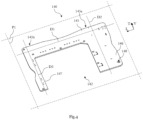
- FIG 4 illustrates, in perspective, the printed circuit board 140 according to a first exemplary embodiment of the present invention.
- at least one cutout 142 is formed in the printed circuit board 140.
- this at least one cutout 142 is arranged opposite the circulation chamber 150.
- the circulation chamber 150 extends, at least partially, through this cutout 142.
- a main extension plane of the printed circuit board 140 cuts, at least partially, this circulation chamber 150.
- the printed circuit board takes a U shape.
- the printed circuit board 140 has at least, in its main extension plane P1, a base 145 from which at least a first branch 146 and at least a second branch 147 extend.
- the base 145 extends, mainly in a first direction D1
- the first branch 146 extends, mainly in a second direction D2 perpendicular, or substantially perpendicular, to the first direction D1
- the second branch 147 extends, mainly in a third direction D3 perpendicular, or substantially perpendicular, to the first direction D1.
- the first direction D1, the second direction D2 and the third direction D3 all three lie in the main extension plane P1 of the printed circuit board 140.
- this main extension plane P1 is a transverse plane when the printed circuit board 140 is received in the housing of the electric heating device.
- the first branch 146 extends from a first side 145a of the base 145 and the second branch 147 extends from a second side 145b of this base 145, the first side 145a and the second side 145b of the base 145 being opposite each other with respect to the first straight line D1 of main extension of the base 145.
- the first branch and the second branch can extend from the same side of the base.
- the base 145 may be arranged facing the second compartment described above and the second branch 147 facing the third compartment.
- the second branch 147 of the printed circuit board may be arranged facing the inlet and outlet hydraulic connection members.
- the cutout 142 formed in this printed circuit board 140 is positioned facing the first compartment which receives the heat transfer fluid circulation chamber.
- At least one orifice 148 is formed in the printed circuit board 140, this at least one orifice 148 being adapted to be arranged opposite the tapping provided in at least one of the pads described above, and this at least one orifice 148 is adapted to receive the at least one fixing device which makes it possible to make the printed circuit board 140 integral with the external wall of the circulation chamber.
- a plurality of orifices 148 are formed on the printed circuit board 140.
- at least as many orifices 148 are formed in the printed circuit board 140 as tappings are formed in the pads, each orifice 148 being adapted to be arranged opposite one of these tappings.
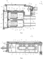
- FIG. 5 finally illustrates the electric heating device 100 according to the invention, shown without its cover.
- this figure 5 makes the printed circuit board 140, here produced according to a second exemplary embodiment, particularly visible.
- the printed circuit board 140 has an L shape, that is to say that it comprises the base 145 and the first branch 146 which extends from this base 145.
- the base 145 is thus arranged opposite the second compartment in which the electrical connection is made between the printed circuit board 140 and the control and power connectors 101, 102 and the first branch 146 is arranged opposite, at least partially, the hydraulic input connection member 103 and the hydraulic output connection member 104.
- the cutout 142 formed in the printed circuit board 140 is arranged opposite the circulation chamber 150.
- this figure 5 makes visible the fixing devices 144 which make it possible to ensure that the printed circuit board 140 is held in position in the internal volume 114 of the housing 110.
- the present invention provides an electric heating device in which the printed circuit board is arranged as close as possible to the heat transfer fluid circulation chamber, thus making it possible to reduce the overall size of the electric heating device, while avoiding the formation of electric arcs between the external wall of the circulation chamber and the potentially dangerous circuit board.
Landscapes
- Engineering & Computer Science (AREA)
- Physics & Mathematics (AREA)
- Thermal Sciences (AREA)
- Mechanical Engineering (AREA)
- Chemical & Material Sciences (AREA)
- Combustion & Propulsion (AREA)
- General Engineering & Computer Science (AREA)
- Microelectronics & Electronic Packaging (AREA)
- Air-Conditioning For Vehicles (AREA)
- Instantaneous Water Boilers, Portable Hot-Water Supply Apparatuses, And Control Of Portable Hot-Water Supply Apparatuses (AREA)
Claims (9)
- Vorrichtung zum elektrischen Erwärmen (100) einer Wärmeträgerflüssigkeit, umfassend mindestens ein Gehäuse (110), das ein Innenvolumen (114) definiert, in dem mindestens eine Zirkulationskammer (150) für die Wärmeträgerflüssigkeit und mindestens eine Leiterplatte (140), die mindestens ein elektrisches und/oder elektronisches Bauteil trägt, untergebracht sind, wobei die Zirkulationskammer (150) der Wärmeträgerflüssigkeit durch mindestens eine Außenwand (159) begrenzt ist, die Zirkulationskammer (150) der Wärmeträgerflüssigkeit mindestens ein elektrisches Erwärmungselement (154, 155) aufnimmt, das elektrisch mit dem mindestens einen elektrischen und/oder elektronischen Bauteil verbunden ist, das von der Leiterplatte (140) getragen wird, wobei die Leiterplatte (140) mindestens einen Ausschnitt (142) umfasst, der gegenüber der Zirkulationskammer (150) der Wärmeträgerflüssigkeit positioniert ist, dadurch gekennzeichnet, dass sich die Zirkulationskammer (150) mindestens teilweise durch den Ausschnitt (142) hindurch erstreckt.
- Vorrichtung zum elektrischen Erwärmen (100) nach Anspruch 1, wobei mindestens ein elektronischer Schalter (141) in dem Innenvolumen (114) des Gehäuses (110) untergebracht ist, wobei das Innenvolumen (114) des Gehäuses (110) mindestens ein erstes Fach (116), das mindestens die Zirkulationskammer (150) der Wärmeträgerflüssigkeit aufnimmt, und mindestens ein zweites Fach (117), das den mindestens einen elektronischen Schalter (141) aufnimmt, umfasst.
- Vorrichtung zum elektrischen Erwärmen (100) nach dem vorhergehenden Anspruch, wobei das Innenvolumen (114) des Gehäuses (110) mindestens ein drittes Fach (119) umfasst, in dem eine elektrische Verbindung zwischen dem mindestens einen elektrischen Erwärmungselement (154, 155) und dem mindestens einen elektrischen und/oder elektronischen Bauteil, das von der Leiterplatte (140) getragen wird, ausgeführt ist.
- Vorrichtung zum elektrischen Erwärmen (100) nach einem der vorhergehenden Ansprüche, wobei die Leiterplatte (140) in ihrer Haupterstreckungsebene (P1) mindestens eine Basis (145), die sich hauptsächlich entlang einer ersten Geraden (D1) erstreckt, und mindestens einen ersten Arm (146) umfasst, der sich hauptsächlich entlang einer zweiten Geraden (D2) erstreckt, die senkrecht oder im Wesentlichen senkrecht zu der ersten Geraden (D1) verläuft.
- Vorrichtung zum elektrischen Erwärmen (100) nach einem der vorhergehenden Ansprüche, wobei die Leiterplatte (140) eine L-Form aufweist.
- Vorrichtung zum elektrischen Erwärmen (100) nach Anspruch 4, wobei die Leiterplatte (140) in ihrer Haupterstreckungsebene (P1) mindestens einen zweiten Arm (147) umfasst, der sich hauptsächlich entlang einer dritten Geraden (D3) erstreckt, die senkrecht oder im Wesentlichen senkrecht zu der ersten Geraden (D1) verläuft.
- Vorrichtung zum elektrischen Erwärmen (100) nach einem der vorhergehenden Ansprüche 1 bis 4 oder 4, wobei die Leiterplatte (140) eine U-Form aufweist.
- Vorrichtung zum elektrischen Erwärmen (100) nach Anspruch 76 oder nach Anspruch 6 in Kombination mit Anspruch 7, wobei sich der erste Arm (146) der Leiterplatte (140) von einer ersten Seite (145a) der Basis (145) erstreckt und wobei sich der zweite Arm (147) von einer zweiten Seite (145b) der Basis (145) entgegengesetzt der ersten Seite in Bezug auf die erste Gerade (D1) erstreckt.
- Vorrichtung zum elektrischen Erwärmen (100) nach einem der vorhergehenden Ansprüche in Kombination mit den Ansprüchen 2 oder 3 und 4, wobei die Basis (145) der Leiterplatte (140) gegenüber dem zweiten Fach (117) positioniert ist, und wobei der in der Leiterplatte ausgebildete Ausschnitt (142) gegenüber dem ersten Fach (116) positioniert ist.
Applications Claiming Priority (2)
| Application Number | Priority Date | Filing Date | Title |
|---|---|---|---|
| FR2008052A FR3113113A1 (fr) | 2020-07-29 | 2020-07-29 | Dispositif de chauffage électrique d’un liquide caloporteur |
| PCT/EP2021/071076 WO2022023383A1 (fr) | 2020-07-29 | 2021-07-27 | Dispositif de chauffage électrique d'un liquide caloporteur |
Publications (2)
| Publication Number | Publication Date |
|---|---|
| EP4189302A1 EP4189302A1 (de) | 2023-06-07 |
| EP4189302B1 true EP4189302B1 (de) | 2025-02-19 |
Family
ID=72885796
Family Applications (1)
| Application Number | Title | Priority Date | Filing Date |
|---|---|---|---|
| EP21749638.9A Active EP4189302B1 (de) | 2020-07-29 | 2021-07-27 | Vorrichtung zum elektrischen erwärmen einer wärmeträgerflüssigkeit |
Country Status (4)
| Country | Link |
|---|---|
| EP (1) | EP4189302B1 (de) |
| CN (1) | CN116157634A (de) |
| FR (1) | FR3113113A1 (de) |
| WO (1) | WO2022023383A1 (de) |
Families Citing this family (2)
| Publication number | Priority date | Publication date | Assignee | Title |
|---|---|---|---|---|
| CN116804491A (zh) * | 2023-05-31 | 2023-09-26 | 浙江三花智能控制股份有限公司 | 电加热器 |
| FR3167076A1 (fr) * | 2024-10-09 | 2026-04-10 | Valeo Systemes Thermiques | Radiateur électrique pour véhicule automobile |
Family Cites Families (9)
| Publication number | Priority date | Publication date | Assignee | Title |
|---|---|---|---|---|
| DE102012013347B4 (de) * | 2012-07-06 | 2022-10-13 | Stiebel Eltron Gmbh & Co. Kg | Elektronische Leiterplatine und Verfahren zum Installieren eines Sensors an einem Heizblock für einen Durchlauferhitzer |
| FR3004058B1 (fr) * | 2013-03-26 | 2016-12-16 | Valeo Systemes Thermiques | Module de commande d'un appareil electrique |
| FR3003809B1 (fr) * | 2013-03-26 | 2016-12-16 | Valeo Systemes Thermiques | Dispositif de chauffage electrique de fluide pour vehicule automobile et circuit de chauffage associe |
| FR3014542B1 (fr) * | 2013-12-05 | 2019-09-13 | Valeo Systemes Thermiques | Dispositif electrique de conditionnement thermique de fluide pour vehicule automobile, et appareil de chauffage et/ou de climatisation associe |
| FR3027558B1 (fr) * | 2014-10-27 | 2018-04-27 | Valeo Systemes Thermiques | Dispositif de chauffage pour unite de climatisation pour vehicule automobile |
| FR3032385B1 (fr) * | 2015-02-10 | 2018-05-25 | Valeo Systemes Thermiques | Boitier d'un dispositif de chauffage electrique |
| DE102017106250A1 (de) * | 2017-03-23 | 2018-09-27 | Webasto SE | Elektrisches Heizgerät |
| CN207803458U (zh) * | 2018-02-05 | 2018-09-04 | 张宇 | 一种大储量烟油电子烟 |
| KR102571467B1 (ko) * | 2018-03-23 | 2023-08-29 | 한온시스템 주식회사 | 냉각수 히터 |
-
2020
- 2020-07-29 FR FR2008052A patent/FR3113113A1/fr not_active Ceased
-
2021
- 2021-07-27 CN CN202180055225.5A patent/CN116157634A/zh active Pending
- 2021-07-27 EP EP21749638.9A patent/EP4189302B1/de active Active
- 2021-07-27 WO PCT/EP2021/071076 patent/WO2022023383A1/fr not_active Ceased
Also Published As
| Publication number | Publication date |
|---|---|
| FR3113113A1 (fr) | 2022-02-04 |
| CN116157634A (zh) | 2023-05-23 |
| WO2022023383A1 (fr) | 2022-02-03 |
| EP4189302A1 (de) | 2023-06-07 |
Similar Documents
| Publication | Publication Date | Title |
|---|---|---|
| EP4189302B1 (de) | Vorrichtung zum elektrischen erwärmen einer wärmeträgerflüssigkeit | |
| EP1998406B1 (de) | Elektrische Anschlussvorrichtung zwischen einer Stromversorgungsquelle und einem elektrischen Heizkörper und Anwendungsverfahren einer solchen Anschlussvorrichtung | |
| FR2808131A1 (fr) | Connecteur electrique | |
| EP3840557B1 (de) | Elektrisches gerät mit einer elektrischen anschlussleiste, die von zwei seiten eines kühlkörpers gekühlt wird | |
| FR3004058A1 (fr) | Module de commande d'un appareil electrique | |
| EP2979523B1 (de) | Steuermodul für eine elektrische anwendung | |
| EP2516938A1 (de) | Elektrisches heizaggregat und zugehöriges montageverfahren | |
| FR2478204A1 (fr) | Dispositif de chauffage applicable a un filtre a carburant | |
| EP2892743B1 (de) | Vorrichtung zur elektrischen erwärmung einer flüssigkeit für ein kraftfahrzeug und zugehöriger heizkreislauf sowie heiz-und/oder klimaanlage | |
| FR3075333A1 (fr) | Echangeur de chaleur pour vehicule | |
| WO2020065170A1 (fr) | Boitier d'interface électronique d'un dispositif de chauffage électrique | |
| FR3081085A1 (fr) | Boitier de securite electrique et de raccordement de cable(s) comportant un dispositif pyrotechnique et des fusibles | |
| EP4078042B1 (de) | Fluidheizvorrichtung, insbesondere für ein fahrzeug | |
| EP4487654B1 (de) | Heizkörper eines elektrischen heizkörpers | |
| FR3105377A1 (fr) | Dispositif de chauffage électrique d’un liquide pour véhicule automobile | |
| FR3107677A1 (fr) | Ensemble de commande et de connexion électrique et dispositif associé | |
| EP4034396B1 (de) | Gehäuse einer elektronischen schnittstelle zur steuerung einer elektrischen heizvorrichtung | |
| FR3130496A1 (fr) | Radiateur électrique d’une installation de ventilation, de chauffage et/ou d’air climatisé. | |
| WO2014154572A1 (fr) | Module de commande d'un appareil electrique | |
| FR3126837A1 (fr) | Radiateur électrique d’une installation de ventilation, de chauffage et/ou d’air climatisé. | |
| FR3149372A1 (fr) | Echangeur de chaleur, système électronique et véhicule automobile associés | |
| EP4641763A1 (de) | Batterie für ein elektrisches oder hybridfahrzeug mit querträgern und verbindern zur bildung einer bahn für ein kühlmittel | |
| EP1981052A1 (de) | Schaltkasten mit Sperr-Relais | |
| FR3071696A1 (fr) | Boitier de commande d'un compresseur electrique prevu pour le refroidissement d'au moins un composant electronique | |
| WO2019002723A1 (fr) | Cadre d'un dispositif de chauffage électrique comprenant des plots de guidage ayant une surface inclinée |
Legal Events
| Date | Code | Title | Description |
|---|---|---|---|
| STAA | Information on the status of an ep patent application or granted ep patent |
Free format text: STATUS: UNKNOWN |
|
| STAA | Information on the status of an ep patent application or granted ep patent |
Free format text: STATUS: THE INTERNATIONAL PUBLICATION HAS BEEN MADE |
|
| PUAI | Public reference made under article 153(3) epc to a published international application that has entered the european phase |
Free format text: ORIGINAL CODE: 0009012 |
|
| STAA | Information on the status of an ep patent application or granted ep patent |
Free format text: STATUS: REQUEST FOR EXAMINATION WAS MADE |
|
| 17P | Request for examination filed |
Effective date: 20230216 |
|
| AK | Designated contracting states |
Kind code of ref document: A1 Designated state(s): AL AT BE BG CH CY CZ DE DK EE ES FI FR GB GR HR HU IE IS IT LI LT LU LV MC MK MT NL NO PL PT RO RS SE SI SK SM TR |
|
| DAV | Request for validation of the european patent (deleted) | ||
| DAX | Request for extension of the european patent (deleted) | ||
| GRAP | Despatch of communication of intention to grant a patent |
Free format text: ORIGINAL CODE: EPIDOSNIGR1 |
|
| STAA | Information on the status of an ep patent application or granted ep patent |
Free format text: STATUS: GRANT OF PATENT IS INTENDED |
|
| INTG | Intention to grant announced |
Effective date: 20240917 |
|
| GRAS | Grant fee paid |
Free format text: ORIGINAL CODE: EPIDOSNIGR3 |
|
| GRAA | (expected) grant |
Free format text: ORIGINAL CODE: 0009210 |
|
| STAA | Information on the status of an ep patent application or granted ep patent |
Free format text: STATUS: THE PATENT HAS BEEN GRANTED |
|
| AK | Designated contracting states |
Kind code of ref document: B1 Designated state(s): AL AT BE BG CH CY CZ DE DK EE ES FI FR GB GR HR HU IE IS IT LI LT LU LV MC MK MT NL NO PL PT RO RS SE SI SK SM TR |
|
| REG | Reference to a national code |
Ref country code: GB Ref legal event code: FG4D Free format text: NOT ENGLISH |
|
| REG | Reference to a national code |
Ref country code: CH Ref legal event code: EP |
|
| REG | Reference to a national code |
Ref country code: IE Ref legal event code: FG4D Free format text: LANGUAGE OF EP DOCUMENT: FRENCH |
|
| REG | Reference to a national code |
Ref country code: DE Ref legal event code: R096 Ref document number: 602021026405 Country of ref document: DE |
|
| REG | Reference to a national code |
Ref country code: NL Ref legal event code: MP Effective date: 20250219 |
|
| PG25 | Lapsed in a contracting state [announced via postgrant information from national office to epo] |
Ref country code: RS Free format text: LAPSE BECAUSE OF FAILURE TO SUBMIT A TRANSLATION OF THE DESCRIPTION OR TO PAY THE FEE WITHIN THE PRESCRIBED TIME-LIMIT Effective date: 20250519 |
|
| PG25 | Lapsed in a contracting state [announced via postgrant information from national office to epo] |
Ref country code: FI Free format text: LAPSE BECAUSE OF FAILURE TO SUBMIT A TRANSLATION OF THE DESCRIPTION OR TO PAY THE FEE WITHIN THE PRESCRIBED TIME-LIMIT Effective date: 20250219 |
|
| PG25 | Lapsed in a contracting state [announced via postgrant information from national office to epo] |
Ref country code: PL Free format text: LAPSE BECAUSE OF FAILURE TO SUBMIT A TRANSLATION OF THE DESCRIPTION OR TO PAY THE FEE WITHIN THE PRESCRIBED TIME-LIMIT Effective date: 20250219 |
|
| PG25 | Lapsed in a contracting state [announced via postgrant information from national office to epo] |
Ref country code: ES Free format text: LAPSE BECAUSE OF FAILURE TO SUBMIT A TRANSLATION OF THE DESCRIPTION OR TO PAY THE FEE WITHIN THE PRESCRIBED TIME-LIMIT Effective date: 20250219 |
|
| REG | Reference to a national code |
Ref country code: LT Ref legal event code: MG9D |
|
| PG25 | Lapsed in a contracting state [announced via postgrant information from national office to epo] |
Ref country code: NO Free format text: LAPSE BECAUSE OF FAILURE TO SUBMIT A TRANSLATION OF THE DESCRIPTION OR TO PAY THE FEE WITHIN THE PRESCRIBED TIME-LIMIT Effective date: 20250519 Ref country code: IS Free format text: LAPSE BECAUSE OF FAILURE TO SUBMIT A TRANSLATION OF THE DESCRIPTION OR TO PAY THE FEE WITHIN THE PRESCRIBED TIME-LIMIT Effective date: 20250619 |
|
| PG25 | Lapsed in a contracting state [announced via postgrant information from national office to epo] |
Ref country code: NL Free format text: LAPSE BECAUSE OF FAILURE TO SUBMIT A TRANSLATION OF THE DESCRIPTION OR TO PAY THE FEE WITHIN THE PRESCRIBED TIME-LIMIT Effective date: 20250219 |
|
| PG25 | Lapsed in a contracting state [announced via postgrant information from national office to epo] |
Ref country code: HR Free format text: LAPSE BECAUSE OF FAILURE TO SUBMIT A TRANSLATION OF THE DESCRIPTION OR TO PAY THE FEE WITHIN THE PRESCRIBED TIME-LIMIT Effective date: 20250219 |
|
| PG25 | Lapsed in a contracting state [announced via postgrant information from national office to epo] |
Ref country code: LV Free format text: LAPSE BECAUSE OF FAILURE TO SUBMIT A TRANSLATION OF THE DESCRIPTION OR TO PAY THE FEE WITHIN THE PRESCRIBED TIME-LIMIT Effective date: 20250219 Ref country code: PT Free format text: LAPSE BECAUSE OF FAILURE TO SUBMIT A TRANSLATION OF THE DESCRIPTION OR TO PAY THE FEE WITHIN THE PRESCRIBED TIME-LIMIT Effective date: 20250620 |
|
| PG25 | Lapsed in a contracting state [announced via postgrant information from national office to epo] |
Ref country code: GR Free format text: LAPSE BECAUSE OF FAILURE TO SUBMIT A TRANSLATION OF THE DESCRIPTION OR TO PAY THE FEE WITHIN THE PRESCRIBED TIME-LIMIT Effective date: 20250520 Ref country code: BG Free format text: LAPSE BECAUSE OF FAILURE TO SUBMIT A TRANSLATION OF THE DESCRIPTION OR TO PAY THE FEE WITHIN THE PRESCRIBED TIME-LIMIT Effective date: 20250219 |
|
| REG | Reference to a national code |
Ref country code: AT Ref legal event code: MK05 Ref document number: 1768588 Country of ref document: AT Kind code of ref document: T Effective date: 20250219 |
|
| PG25 | Lapsed in a contracting state [announced via postgrant information from national office to epo] |
Ref country code: SE Free format text: LAPSE BECAUSE OF FAILURE TO SUBMIT A TRANSLATION OF THE DESCRIPTION OR TO PAY THE FEE WITHIN THE PRESCRIBED TIME-LIMIT Effective date: 20250219 |
|
| PG25 | Lapsed in a contracting state [announced via postgrant information from national office to epo] |
Ref country code: SM Free format text: LAPSE BECAUSE OF FAILURE TO SUBMIT A TRANSLATION OF THE DESCRIPTION OR TO PAY THE FEE WITHIN THE PRESCRIBED TIME-LIMIT Effective date: 20250219 |
|
| PG25 | Lapsed in a contracting state [announced via postgrant information from national office to epo] |
Ref country code: DK Free format text: LAPSE BECAUSE OF FAILURE TO SUBMIT A TRANSLATION OF THE DESCRIPTION OR TO PAY THE FEE WITHIN THE PRESCRIBED TIME-LIMIT Effective date: 20250219 |
|
| PGFP | Annual fee paid to national office [announced via postgrant information from national office to epo] |
Ref country code: DE Payment date: 20250711 Year of fee payment: 5 |
|
| PG25 | Lapsed in a contracting state [announced via postgrant information from national office to epo] |
Ref country code: IT Free format text: LAPSE BECAUSE OF FAILURE TO SUBMIT A TRANSLATION OF THE DESCRIPTION OR TO PAY THE FEE WITHIN THE PRESCRIBED TIME-LIMIT Effective date: 20250219 |
|
| PG25 | Lapsed in a contracting state [announced via postgrant information from national office to epo] |
Ref country code: AT Free format text: LAPSE BECAUSE OF FAILURE TO SUBMIT A TRANSLATION OF THE DESCRIPTION OR TO PAY THE FEE WITHIN THE PRESCRIBED TIME-LIMIT Effective date: 20250219 |
|
| PG25 | Lapsed in a contracting state [announced via postgrant information from national office to epo] |
Ref country code: EE Free format text: LAPSE BECAUSE OF FAILURE TO SUBMIT A TRANSLATION OF THE DESCRIPTION OR TO PAY THE FEE WITHIN THE PRESCRIBED TIME-LIMIT Effective date: 20250219 Ref country code: CZ Free format text: LAPSE BECAUSE OF FAILURE TO SUBMIT A TRANSLATION OF THE DESCRIPTION OR TO PAY THE FEE WITHIN THE PRESCRIBED TIME-LIMIT Effective date: 20250219 |
|
| PG25 | Lapsed in a contracting state [announced via postgrant information from national office to epo] |
Ref country code: RO Free format text: LAPSE BECAUSE OF FAILURE TO SUBMIT A TRANSLATION OF THE DESCRIPTION OR TO PAY THE FEE WITHIN THE PRESCRIBED TIME-LIMIT Effective date: 20250219 |
|
| PG25 | Lapsed in a contracting state [announced via postgrant information from national office to epo] |
Ref country code: SK Free format text: LAPSE BECAUSE OF FAILURE TO SUBMIT A TRANSLATION OF THE DESCRIPTION OR TO PAY THE FEE WITHIN THE PRESCRIBED TIME-LIMIT Effective date: 20250219 |
|
| REG | Reference to a national code |
Ref country code: DE Ref legal event code: R097 Ref document number: 602021026405 Country of ref document: DE |
|
| PLBE | No opposition filed within time limit |
Free format text: ORIGINAL CODE: 0009261 |
|
| STAA | Information on the status of an ep patent application or granted ep patent |
Free format text: STATUS: NO OPPOSITION FILED WITHIN TIME LIMIT |
|
| REG | Reference to a national code |
Ref country code: CH Ref legal event code: L10 Free format text: ST27 STATUS EVENT CODE: U-0-0-L10-L00 (AS PROVIDED BY THE NATIONAL OFFICE) Effective date: 20251231 |
|
| 26N | No opposition filed |
Effective date: 20251120 |
|
| REG | Reference to a national code |
Ref country code: CH Ref legal event code: H13 Free format text: ST27 STATUS EVENT CODE: U-0-0-H10-H13 (AS PROVIDED BY THE NATIONAL OFFICE) Effective date: 20260224 |
|
| PG25 | Lapsed in a contracting state [announced via postgrant information from national office to epo] |
Ref country code: LU Free format text: LAPSE BECAUSE OF NON-PAYMENT OF DUE FEES Effective date: 20250727 |
|
| GBPC | Gb: european patent ceased through non-payment of renewal fee |
Effective date: 20250727 |
|
| REG | Reference to a national code |
Ref country code: BE Ref legal event code: MM Effective date: 20250731 |
|
| PG25 | Lapsed in a contracting state [announced via postgrant information from national office to epo] |
Ref country code: GB Free format text: LAPSE BECAUSE OF NON-PAYMENT OF DUE FEES Effective date: 20250727 |
|
| PG25 | Lapsed in a contracting state [announced via postgrant information from national office to epo] |
Ref country code: BE Free format text: LAPSE BECAUSE OF NON-PAYMENT OF DUE FEES Effective date: 20250731 |
|
| PG25 | Lapsed in a contracting state [announced via postgrant information from national office to epo] |
Ref country code: FR Free format text: LAPSE BECAUSE OF NON-PAYMENT OF DUE FEES Effective date: 20250731 |
|
| PG25 | Lapsed in a contracting state [announced via postgrant information from national office to epo] |
Ref country code: CH Free format text: LAPSE BECAUSE OF NON-PAYMENT OF DUE FEES Effective date: 20250731 |