EP4187945B1 - Energiearme gegenseitige detektion von nahbereichssendeempfängern - Google Patents
Energiearme gegenseitige detektion von nahbereichssendeempfängern Download PDFInfo
- Publication number
- EP4187945B1 EP4187945B1 EP21217410.6A EP21217410A EP4187945B1 EP 4187945 B1 EP4187945 B1 EP 4187945B1 EP 21217410 A EP21217410 A EP 21217410A EP 4187945 B1 EP4187945 B1 EP 4187945B1
- Authority
- EP
- European Patent Office
- Prior art keywords
- time
- monitoring device
- selected amount
- monitoring
- nearby
- Prior art date
- Legal status (The legal status is an assumption and is not a legal conclusion. Google has not performed a legal analysis and makes no representation as to the accuracy of the status listed.)
- Active
Links
Images



Classifications
-
- H—ELECTRICITY
- H04—ELECTRIC COMMUNICATION TECHNIQUE
- H04W—WIRELESS COMMUNICATION NETWORKS
- H04W8/00—Network data management
- H04W8/005—Discovery of network devices, e.g. terminals
-
- G—PHYSICS
- G01—MEASURING; TESTING
- G01S—RADIO DIRECTION-FINDING; RADIO NAVIGATION; DETERMINING DISTANCE OR VELOCITY BY USE OF RADIO WAVES; LOCATING OR PRESENCE-DETECTING BY USE OF THE REFLECTION OR RERADIATION OF RADIO WAVES; ANALOGOUS ARRANGEMENTS USING OTHER WAVES
- G01S5/00—Position-fixing by co-ordinating two or more direction or position line determinations; Position-fixing by co-ordinating two or more distance determinations
- G01S5/02—Position-fixing by co-ordinating two or more direction or position line determinations; Position-fixing by co-ordinating two or more distance determinations using radio waves
- G01S5/14—Determining absolute distances from a plurality of spaced points of known location
-
- H—ELECTRICITY
- H04—ELECTRIC COMMUNICATION TECHNIQUE
- H04Q—SELECTING
- H04Q9/00—Arrangements in telecontrol or telemetry systems for selectively calling a substation from a main station, in which substation desired apparatus is selected for applying a control signal thereto or for obtaining measured values therefrom
-
- H—ELECTRICITY
- H04—ELECTRIC COMMUNICATION TECHNIQUE
- H04W—WIRELESS COMMUNICATION NETWORKS
- H04W4/00—Services specially adapted for wireless communication networks; Facilities therefor
- H04W4/80—Services using short range communication, e.g. near-field communication [NFC], radio-frequency identification [RFID] or low energy communication
-
- H—ELECTRICITY
- H04—ELECTRIC COMMUNICATION TECHNIQUE
- H04Q—SELECTING
- H04Q2209/00—Arrangements in telecontrol or telemetry systems
- H04Q2209/40—Arrangements in telecontrol or telemetry systems using a wireless architecture
-
- H—ELECTRICITY
- H04—ELECTRIC COMMUNICATION TECHNIQUE
- H04Q—SELECTING
- H04Q2209/00—Arrangements in telecontrol or telemetry systems
- H04Q2209/80—Arrangements in the sub-station, i.e. sensing device
- H04Q2209/84—Measuring functions
- H04Q2209/845—Measuring functions where the measuring is synchronized between sensing devices
-
- H—ELECTRICITY
- H04—ELECTRIC COMMUNICATION TECHNIQUE
- H04W—WIRELESS COMMUNICATION NETWORKS
- H04W52/00—Power management, e.g. Transmission Power Control [TPC] or power classes
- H04W52/02—Power saving arrangements
- H04W52/0209—Power saving arrangements in terminal devices
Definitions
- the present disclosure relates generally to an electronic monitoring device for attaching to a limb of a person and more specifically wherein the electronic monitoring device is able to detect other electronic monitoring devices in its vicinity.
- a body worn electronic monitoring device it is common practice today to attach a body worn electronic monitoring device to a person for monitoring their location and/or enforcing a location based policy such as house arrest, curfew sentencing, pre-trial sentencing, parole, probation and a restraining order.
- a location based policy such as house arrest, curfew sentencing, pre-trial sentencing, parole, probation and a restraining order.
- the electronic monitoring device is attached with a strap to the ankle of the person or to other limbs, for example the wrist of the person. It is typically complicated to remove the electronic monitoring device and the person is prohibited from removing the electronic monitoring device to prevent violating a location based policy.
- each device When enforcing a restraining order, the user may be prohibited from coming near another person bearing or wearing another electronic monitoring device.
- One option to enforce such a policy would be for each device to continuously notify a server of its location. However this places a large burden on the server to compare the location of each device with all other devices to prevent any device from violating rules, for example for one device to come near another. Additionally if one of the devices loses communication with the server, the server is unaware of its location and cannot notify the other devices.
- the devices may transmit a short range signal continuously so that any device can detect if any other device is in the vicinity.
- the devices are generally battery powered. Such a method consumes a lot of energy and would generally cause the battery to be depleted very quickly.
- Bluetooth transceivers search for nearby transceivers only during the "pairing" process.
- WiFi transceivers search for nearby transceivers only while connecting to a new network.
- Bluetooth and WiFi can use a brute force method for a limited period of time and there is no problem with battery consumption.
- the electronic monitoring devices would need to continuously search to prevent prohibited devices from approaching them.
- One such example can be found in US 9 668 209 wherein the BLE interface timing is composed of three time windows due to the clock drifting between two discovering low energy devices.
- An aspect of an embodiment of the disclosure relates to a monitor device that periodically checks if other monitoring devices are in the nearby area.
- the monitoring devices are all equipped with a real-time clock to keep track of the time and attempt to keep the monitoring devices synchronized. At periodic preselected times all the devices attempt to search for other monitoring devices and transmit a control signal that provides information of the identity of the monitoring device.
- the monitoring devices all execute a common method of communication to enable each device to transmit its control signal and receive the control signals of all the other devices in the nearby area and prevent transmission collisions. In order to conserve energy the monitoring devices do not communicate continuously but rather only at about the periodic preselected times.
- the common method uses three stages. In the first stage all the devices listen for a first selected amount of time to detect monitoring devices with real-time clocks that start earlier than other monitoring devices. In the second stage all the devices are set with a different delay time value so that each will attempt to transmit at a different time to prevent transmission collisions. Each monitoring device listens during the delay time and when the monitoring device's delay time is over and nobody is transmitting the monitoring device begins to transmit.
- the monitoring device If the monitoring device detects transmission by another device the monitoring device waits until the end of the transmission, records the identity of the transmitting monitoring device and then waits again for the delay time before transmitting its control signal, once the monitoring device succeeds to transmit the control signal it activates a third stage wherein the monitoring device listens for a third selected amount of time for control signals of other monitoring devices in the nearby area that did not yet transmit their control signal.
- a method of detecting nearby monitoring devices by a monitoring device comprising:
- the monitoring device waits until the end of the transmission of the control signal and records the identity of the nearby monitoring device detected;
- the monitoring device resumes monitoring in receive mode until completing the respective selected amount of time; during the second selected amount of time the monitoring device restarts stage b after recording the identity of the detected nearby monitoring device, without transmitting the control signal of the monitoring device.
- the second selected amount of time is unique for each monitoring device.
- the second selected amount of time is randomly selected.
- the second selected amount of time is reselected each time stage b is restarted.
- the first selected amount of time and third selected amount of time are selected based on the number of monitoring devices expected to be nearby.
- the first selected amount of time and third selected amount of time are the same for all the monitoring devices.
- the first selected amount of time and third selected amount of time are the same for each monitoring device.
- communication time to detect nearby monitoring devices is less than a tenth of a time between two consecutive periodic preselected times.
- the first selected amount of time is selected as a function of the accuracy of the internal real-time clock of the monitoring devices and accuracy of the synchronization between the monitoring devices.
- the second selected amount of time is smaller than the third selected amount of time.
- a monitoring device comprising:
- the monitoring device waits until the end of the transmission of the control signal and records the identity of the nearby monitoring device detected;
- the monitoring device resumes monitoring in receive mode until completing the respective selected amount of time; during the second selected amount of time the monitoring device restarts stage b after recording the identity of the detected nearby monitoring device, without transmitting the control signal of the monitoring device.
- Fig. 1 is a schematic illustration of a system 100 for monitoring a group of electronic monitoring devices 110, according to an embodiment of the disclosure.
- each monitoring device 110 communicates with a central server 130 over a network 140.
- local routers 120 are installed at specific geographic locations and each monitoring device 110 communicates with the central server 130 via the local router 120 and network 140.
- local routers 120 can be domestic Wi-Fi routers, cellular base stations or other types of local communication routers.
- each monitoring device 110 includes a short range transceiver 112, which is configured to use a low energy short range communication signal 105 to notify other monitoring devices 110 in the vicinity that the monitoring device 110 is near and to search for the existence of other monitoring devices 110 in the vicinity.
- each monitoring device 110 includes also a processor 118 and memory 116 to enable execution of a program that uses the method below to enable multiple monitoring devices to synchronously notify each other that they are in the vicinity.
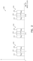
- Fig. 2 is a schematic illustration of a timeline 200 of local transmissions of short range communication signals 105 by monitoring device 110, according to an embodiment of the disclosure.
- each monitoring device 110 is synchronized to initialize transmission of a control signal M periodically based on periodic preselected times T. For example at about the beginning of every minute "t" according to a common world clock and every k seconds afterwards (t, t+k, t+2k...) where k is e.g. every 10-30 second.
- each monitoring device 110 searches for other monitoring devices 110 nearby and takes a turn to transmit its control signal M, which identifies the monitoring device 110.
- all the monitoring devices 110 are activated for specific time intervals 210 (e.g. every 10-20 seconds for about 1 second) only at about the preselected times T and they do not need to be active continuously to prevent missing transmissions of monitoring devices 110 in the vicinity.
- each monitoring device 110 will perform the method described below, to prevent transmission collisions and to assure that all the monitoring devices 110 in a nearby area will each have a turn to transmit their control signal M and identify all the other monitoring devices 110 in the vicinity.
- the method includes forming the specific time interval 210 from three stages:
- Fig. 3 is a schematic illustration of a timeline 300 of the periodic preselected times T as seen by three monitoring devices 110, according to an exemplary embodiment of the disclosure.
- each monitoring device (1, 2, 3) includes a real time clock (RTC) 114 ( Fig. 1 ) to keep track of the time, so that all the monitoring devices will be synchronized to initialize transmission of their control signal M during the common time interval 210 by the method described below at around the preselected times T (T1, T2, T3) as measured by each monitoring device 110.
- RTC 114 is kept accurate for example by:
- the actual RTC 114 of each monitoring device 110 may differ by a few milliseconds (e.g. 0-100 milliseconds).
- all the monitoring devices 110 will listen and take turns transmitting their control packet M.
- the monitoring devices 110 use the method described below to prevent transmission collisions and enable each of the monitoring devices 110 in the vicinity to transmit their control signal M, while the other monitoring devices 110 in the vicinity listen.
- Fig. 4 is a flow diagram of a method 400 practiced by each monitoring device 110 to detect other monitoring devices 110 nearby, according to an embodiment of the disclosure.
- each monitoring device 110 when approaching the periodic preselected times T each monitoring device 110 performs method 400 to determine if any other monitoring devices 110 are nearby.
- the monitoring device 110 turns on (410) an initial receive mode (RX) for the first selected amount of time Tpre (e.g. between 100-500 milliseconds) before the preselected times T (first stage 212).
- the initial receive mode catches monitoring devices 110 that have a real time clock 114, which is early, causing them to start transmitting before the preselected times T for some of the monitoring devices 110.
- receive mode the monitoring device 110 attempts to detect (420) control signals M from other monitoring devices 110.
- the monitoring device 110 detects a control signal M, then it waits (425) until the end of the control signal M and records the identity of the other monitoring device 110 in the vicinity.
- the recording may be initially to memory 116 and may be transmitted to server 130 over network 140 to act on the information.
- a control signal M may take 5-10 milliseconds to be transmitted. If no control signal M was detected during the first selected amount of time Tpre or the monitoring device 110 finished receiving the control signal M and the first selected amount of time is finished, then monitoring device 110 initiates the second stage 214. It should be noted that after receiving a control signal M during the first stage 212, monitoring device 110 continues to listen for other control signals M.
- the second stage 214 includes setting (430) the delay time D (e.g. between about 2-30 milliseconds depending on the number of monitoring devices 110 expected to be in the vicinity) for the monitoring device 110 to listen in receive mode (RX) before transmitting the monitoring device's control signal M.
- delay time D is randomly generated or preselected for each monitoring device 110.
- the delay time D is a unique value for each monitoring device.
- the delay time D may be set once or each time the monitoring device 110 is about to transmit.
- Monitoring device 110 then turns on (440) receive mode for D milliseconds.
- the delay time assures that each monitoring device 110 will transmit at a different time even if the monitoring devices' real time clocks 114 are perfectly synchronized, since generally each monitoring device 110 sets a different value for the delay.
- monitoring device 110 detects (450) another device transmitting a control signal M during the delay D, it will wait (455) until the end of the transmission and record the identity of the transmitting monitoring device 110. Then monitoring device 110 will again turn on (440) receive mode for D milliseconds. After not detecting other monitoring devices 110 transmitting during the D milliseconds the monitoring device 110 transmits (460) its control signal M for other monitoring devices 110 to receive notification of the existence of the monitoring device 110 in the vicinity.
- the delay time D and control signal M transmission time together may take about 5-50 milliseconds.
- delay time D is much shorter than Tpre and Tpost.
- the delay time D may be started over more than once if the transmission of control signals M from other monitoring devices are detected while waiting for the delay time.
- each time monitoring device 110 is ready to transmit its control signal the monitoring device 110 will first wait for delay time D before transmitting.
- the monitoring device 110 transmits (460) its control signal M, it turns on (470) receive mode again for the third selected amount of time Tpost to detect monitoring devices 110 that transmit after monitoring device 110 successfully transmitted.
- the third selected amount of time Tpost may be about 100-500 milliseconds.
- the time interval for receiving and transmitting control signals may be less than or about 1 second.
- communication time to detect nearby monitoring devices is less than a tenth or a twentieth of the time between two consecutive periodic preselected times T (e.g. t and t+k).
- the third selected amount of time Tpost is much larger than the delay time D used by the monitoring devices, for example 5, 10, 15 or 20 times larger, so that any nearby monitoring devices 110 that did not manage to transmit during the first selected amount of time Tpre or the second selected amount of time D, will manage to transmit during the third selected amount of time Tpost.
- the value of the third selected amount of time Tpost may be increased if many devices are expected to be in the vicinity (e.g. more than 5, 10, 15 or 20), then the value of the third selected amount of time Tpost may be increased.
- Tpre and Tpost may be different for each monitoring device 110 or may be the same for all monitoring devices 110. Likewise Tpre may be the same as Tpost or may be different.
- the values of Tpre and Tpost are set according to the environment in which the user of the monitoring device is expected to be located. For example if the monitoring device is expected to be in the same area with many other monitoring devices 110, Tpre and Tpost may be increased to handle many devices. If the monitoring device is expected to be in a location with only a few monitoring devices 110, Tpre and Tpost may be reduced. Optionally, Tpre may be reduced if the real-time clocks 114 are accurate and the monitoring devices 110 are almost entirely synchronized. In some embodiments of the disclosure, Tpre and/or Tpost may be given random values.
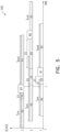
- Fig. 5 is a schematic illustration of a timeline 500 of three monitoring devices 110 implementing the above method of detecting monitoring devices 110 in their vicinity, according to an embodiment of the disclosure.
- each monitoring device 110 uses its short range transceiver 112 to perform the method of detecting other nearby monitoring devices (e.g. within a range of up to about 100-200 meters). As shown in Fig. 5 the first monitoring device 110 (with transceiver 1) performed the following:
- transceiver 1 was able to detect transceiver 3 (at step d) and transceiver 2 (at step i).
- the second monitoring device 110 (with transceiver 2) performed the following:
- transceiver 2 was able to detect transceiver 3 (at step d) and transceiver 1 (at step g).
- the third monitoring device 110 (with transceiver 3) performed the following:
- transceiver 3 was able to detect transceiver 1 (at step f) and transceiver 2 (at step i) during the specific time interval 210.
- each monitoring device 110 was able to transmit its control signal M and detect the control signal M of all the other monitoring devices 110 in the vicinity.
- the above example relates to three monitoring devices 110, however the method may be applied for any number of devices.
- the values of Tpre and Tpost may be adjusted according to the number of expected nearby monitoring devices 110.
- not all the features shown above in a particular embodiment are necessary in every embodiment of the disclosure. Further combinations of the above features are also considered to be within the scope of some embodiments of the disclosure. It will also be appreciated by persons skilled in the art that the present disclosure is not limited to what has been particularly shown and described hereinabove but rather will be defined by the claims.
Landscapes
- Engineering & Computer Science (AREA)
- Computer Networks & Wireless Communication (AREA)
- Signal Processing (AREA)
- Databases & Information Systems (AREA)
- Physics & Mathematics (AREA)
- General Physics & Mathematics (AREA)
- Radar, Positioning & Navigation (AREA)
- Remote Sensing (AREA)
- Mobile Radio Communication Systems (AREA)
- Radar Systems Or Details Thereof (AREA)
- Alarm Systems (AREA)
Claims (15)
- Verfahren zum Detektieren von in der Nähe liegenden Überwachungsvorrichtungen durch eine Überwachungsvorrichtung, umfassend:Verwenden einer internen Echtzeituhr, um periodische vorgewählte Zeiten zu verfolgen, zu denen die Überwachungsvorrichtungen versuchen, miteinander zu kommunizieren;bei Annäherung an die vorgewählten Zeitpunkte, Verwenden eines Prozessors und eines Sendeempfängers mit kurzer Reichweite, um folgende drei Schritte durchzuführen:a) Versetzen der Überwachungsvorrichtung in den Empfangsmodus für eine erste ausgewählte Zeitdauer vor Erreichen der periodischen vorgewählten Zeiten und Abhören auf eine Sendeüberwachungsvorrichtung identifizierende Kontrollsignale durch nahe gelegene Überwachungsvorrichtungen;b) Versetzen der Überwachungsvorrichtung in den Empfangsmodus für eine zweite ausgewählte Zeitdauer und nach Ablauf dieser Zeit, ohne dass in der Nähe befindliche Überwachungsvorrichtungen erfasst wurden, sendet die Überwachungsvorrichtung ihr Steuersignal;c) Versetzen der Überwachungsvorrichtung in den Empfangsmodus für eine dritte ausgewählte Zeitdauer nach Übermittlung des Kontrollsignals;in jeder Stufe während des Empfangsmodus bei Detektierung eines von einer nahe gelegenen Überwachungsvorrichtung gesendeten Kontrollsignals, die Überwachungsvorrichtung bis zum Ende der Übertragung des Kontrollsignals wartet und die Identität der detektierten nahe gelegenen Überwachungsvorrichtung aufzeichnet;während der ersten ausgewählten Zeitdauer und der dritten ausgewählten Zeitdauer setzt die Überwachungsvorrichtung die Überwachung im Empfangsmodus fort, bis zur Beendigung der jeweiligen ausgewählten Zeitdauer; während der zweiten ausgewählten Zeitdauer startet die Überwachungsvorrichtung erneut mit der Stufe b, nachdem sie die Identität der erkannten nahe gelegenen Überwachungsvorrichtung aufgezeichnet hat, ohne das Kontrollsignal der Überwachungsvorrichtung zu übertragen.
- Verfahren nach Anspruch 1, wobei die zweite ausgewählte Zeitdauer für jede Überwachungsvorrichtung einzigartig ist.
- Verfahren nach Anspruch 1, wobei die zweite ausgewählte Zeitdauer zufällig ausgewählt wird.
- Verfahren nach Anspruch 3, wobei die zweite gewählte Zeitdauer jedes Mal neu gewählt wird, wenn die Stufe b neu gestartet wird.
- Verfahren nach Anspruch 1, wobei die erste gewählte Zeitdauer und die dritte gewählte Zeitdauer auf der Grundlage der Anzahl der in der Nähe zu erwartenden Überwachungsvorrichtungen gewählt werden.
- Verfahren nach Anspruch 1, wobei die erste gewählte Zeitdauer und die dritte gewählte Zeitdauer für alle Überwachungsvorrichtungen die gleiche ist.
- Verfahren nach Anspruch 1, wobei die erste ausgewählte Zeitdauer und die dritte ausgewählte Zeitdauer für jede Überwachungseinrichtung die gleiche ist.
- Verfahren nach Anspruch 1, wobei die Kommunikationszeit zur Detektierung von in der Nähe befindlichen Überwachungsvorrichtungen weniger als ein Zehntel der Zeit zwischen zwei aufeinanderfolgenden periodisch vorgewählten Zeiten beträgt.
- Verfahren nach Anspruch 1, wobei die erste ausgewählte Zeitdauer in Funktion der Genauigkeit der internen Echtzeituhr der Überwachungsvorrichtungen und der Synchronisationsgenauigkeit zwischen den Überwachungsvorrichtungen ausgewählt wird.
- Verfahren nach Anspruch 1, wobei die zweite ausgewählte Zeitdauer kleiner ist als die dritte ausgewählte Zeitdauer.
- Überwachungsvorrichtung (110), umfassend:einen Prozessor (118) und einen Speicher (116), die zum Speichern und Ausführen eines Programms zur Detektion in der Nähe befindlicher Überwachungsvorrichtungen konfiguriert sind;eine Echtzeituhr (114), die zum Verfolgen periodischer vorgewählter Zeiten für die Überwachungsvorrichtungen zur Kommunikation mit in der Nähe befindlichen Überwachungsvorrichtungen konfiguriert ist;einen Kurzstrecken-Sendeempfänger (112), der zur Kommunikation mit in der Nähe befindlichen Überwachungsvorrichtungen konfiguriert ist;wobei der Prozessor ein Programm ausführt, um die folgenden drei Schritte bei Annäherung an die periodisch vorgewählten Zeiten durchzuführen:a) Versetzen der Überwachungsvorrichtung in den Empfangsmodus für eine erste ausgewählte Zeitdauer vor Erreichen der periodischen vorgewählten Zeiten und Abhören auf eine kommunizierende Sendeüberwachungsvorrichtung identifizierende Kontrollsignale durch nahe gelegene Überwachungsvorrichtungen;b) Versetzen der Überwachungsvorrichtung in den Empfangsmodus für eine zweite ausgewählte Zeitdauer und nach Ablauf dieser Zeit, ohne dass in der Nähe befindliche Überwachungsvorrichtungen erfasst wurden, sendet die Überwachungsvorrichtung ihr Steuersignal;c) Versetzen der Überwachungsvorrichtung in den Empfangsmodus für eine dritte ausgewählte Zeitdauer nach Übermittlung des Kontrollsignals;in jeder Stufe während des Empfangsmodus bei Detektierung eines von einer nahe gelegenen Überwachungsvorrichtung gesendeten Kontrollsignals die Überwachungsvorrichtung bis zum Ende der Übertragung des Kontrollsignals wartet und die Identität der detektierten nahe gelegenen Überwachungsvorrichtung aufzeichnet;während der ersten ausgewählten Zeitdauer und der dritten ausgewählten Zeitdauer setzt die Überwachungsvorrichtung die Überwachung im Empfangsmodus fort, bis zur Beendigung der jeweiligen ausgewählten Zeitdauer; während der zweiten ausgewählten Zeitdauer startet die Überwachungsvorrichtung erneut mit der Stufe b, nachdem sie die Identität der erkannten nahe gelegenen Überwachungsvorrichtung aufgezeichnet hat, ohne das Kontrollsignal der Überwachungsvorrichtung zu übertragen.
- Überwachungsvorrichtung nach Anspruch 11, wobei die zweite ausgewählte Zeitdauer für jede Überwachungsvorrichtung einzigartig ist.
- Überwachungsvorrichtung nach Anspruch 11, wobei die zweite ausgewählte Zeitdauer zufällig ausgewählt wird.
- Überwachungsvorrichtung nach Anspruch 13, wobei die zweite gewählte Zeitdauer jedes Mal neu gewählt wird, wenn die Stufe b neu gestartet wird.
- Überwachungsvorrichtung nach Anspruch 11, wobei die erste gewählte Zeitdauer und die dritte gewählte Zeitdauer auf der Grundlage der Anzahl der in der Nähe zu erwartenden Überwachungsvorrichtungen gewählt werden.
Applications Claiming Priority (1)
| Application Number | Priority Date | Filing Date | Title |
|---|---|---|---|
| IL288494A IL288494B2 (en) | 2021-11-28 | 2021-11-28 | Mutual detection of short-range transmitters in the near environment at low energy |
Publications (2)
| Publication Number | Publication Date |
|---|---|
| EP4187945A1 EP4187945A1 (de) | 2023-05-31 |
| EP4187945B1 true EP4187945B1 (de) | 2024-04-10 |
Family
ID=79021676
Family Applications (1)
| Application Number | Title | Priority Date | Filing Date |
|---|---|---|---|
| EP21217410.6A Active EP4187945B1 (de) | 2021-11-28 | 2021-12-23 | Energiearme gegenseitige detektion von nahbereichssendeempfängern |
Country Status (5)
| Country | Link |
|---|---|
| US (1) | US11924912B2 (de) |
| EP (1) | EP4187945B1 (de) |
| AU (1) | AU2021286318A1 (de) |
| ES (1) | ES2983479T3 (de) |
| IL (1) | IL288494B2 (de) |
Families Citing this family (1)
| Publication number | Priority date | Publication date | Assignee | Title |
|---|---|---|---|---|
| US11968257B2 (en) * | 2022-01-14 | 2024-04-23 | TurbineOne, Inc. | Pruning a distributed database for an ad-hoc peer-to-peer (P2P) network |
Family Cites Families (3)
| Publication number | Priority date | Publication date | Assignee | Title |
|---|---|---|---|---|
| JP4081424B2 (ja) * | 2003-10-09 | 2008-04-23 | 沖電気工業株式会社 | 無線通信システムとその消費電力低減方法 |
| US9204244B2 (en) * | 2013-04-08 | 2015-12-01 | Nokia Technologies Oy | Method, apparatus, and computer program product for synchronization packet transmitter selection in a wireless network |
| US9668209B1 (en) | 2016-06-29 | 2017-05-30 | Silicon Laboratories Finland Oy | Listening window adjustments for power savings in bluetooth low energy (BLE) communications |
-
2021
- 2021-11-28 IL IL288494A patent/IL288494B2/en unknown
- 2021-12-15 US US17/551,212 patent/US11924912B2/en active Active
- 2021-12-15 AU AU2021286318A patent/AU2021286318A1/en active Pending
- 2021-12-23 ES ES21217410T patent/ES2983479T3/es active Active
- 2021-12-23 EP EP21217410.6A patent/EP4187945B1/de active Active
Also Published As
| Publication number | Publication date |
|---|---|
| IL288494A (en) | 2023-06-01 |
| IL288494B1 (en) | 2024-12-01 |
| IL288494B2 (en) | 2025-04-01 |
| US20230171578A1 (en) | 2023-06-01 |
| EP4187945A1 (de) | 2023-05-31 |
| ES2983479T3 (es) | 2024-10-23 |
| AU2021286318A1 (en) | 2023-06-15 |
| US11924912B2 (en) | 2024-03-05 |
Similar Documents
| Publication | Publication Date | Title |
|---|---|---|
| US7903601B2 (en) | Asynchronous dynamic network discovery for low power systems | |
| AU766345B2 (en) | Radio receivers | |
| US20180063784A1 (en) | Devices and methods for an efficient wakeup protocol | |
| EP2686837B1 (de) | Überwachung von haustieren | |
| JP2017514374A5 (de) | ||
| US10135494B2 (en) | Connection and synchronization with a device in a non-active state based on near field communication | |
| US20100231379A1 (en) | Initiating emergency communication in response to detecting bio-feedback satisfying an alert condition | |
| US11924912B2 (en) | Low energy mutual detection of nearby short range transceivers | |
| US20220278938A1 (en) | Window widening | |
| JP6399428B2 (ja) | 通信装置及びそれを用いた通信システム | |
| JP2025503195A (ja) | 参照信号の有効持続期間の決定方法、装置及び端末 | |
| EP3094139A1 (de) | Kleinleistungsdatenübertragungsprotokoll | |
| JP7736721B2 (ja) | 近接検出システム | |
| WO2022033097A1 (zh) | 目标对象的捕获方法及装置、系统和存储介质 | |
| KR102437617B1 (ko) | 위치 추적 시스템 | |
| Delle Donne et al. | Backing out of backscatter for intermittent wireless networks | |
| JP2017163356A (ja) | 無線標識装置及び無線標識装置の制御方法 | |
| CN117119563A (zh) | 信号发送方法、信号发送处理方法及相关设备 | |
| JP2013088344A (ja) | 無線通信装置 | |
| SE1130067A1 (sv) | Transpondersystem | |
| JP4721849B2 (ja) | 時刻同期システム、計時機器、および、送信タイミング制御方法 | |
| CN116489761B (zh) | 无线对时方法、装置、对时器和传感器 | |
| US20260067818A1 (en) | Transmission processing method and apparatus, terminal, and network side device | |
| WO2018077070A1 (zh) | 提醒事件的执行方法及装置 | |
| CN109672983A (zh) | 定位追踪系统、定位装置及其定位追踪方法 |
Legal Events
| Date | Code | Title | Description |
|---|---|---|---|
| PUAI | Public reference made under article 153(3) epc to a published international application that has entered the european phase |
Free format text: ORIGINAL CODE: 0009012 |
|
| STAA | Information on the status of an ep patent application or granted ep patent |
Free format text: STATUS: THE APPLICATION HAS BEEN PUBLISHED |
|
| AK | Designated contracting states |
Kind code of ref document: A1 Designated state(s): AL AT BE BG CH CY CZ DE DK EE ES FI FR GB GR HR HU IE IS IT LI LT LU LV MC MK MT NL NO PL PT RO RS SE SI SK SM TR |
|
| STAA | Information on the status of an ep patent application or granted ep patent |
Free format text: STATUS: REQUEST FOR EXAMINATION WAS MADE |
|
| 17P | Request for examination filed |
Effective date: 20230706 |
|
| RBV | Designated contracting states (corrected) |
Designated state(s): AL AT BE BG CH CY CZ DE DK EE ES FI FR GB GR HR HU IE IS IT LI LT LU LV MC MK MT NL NO PL PT RO RS SE SI SK SM TR |
|
| GRAP | Despatch of communication of intention to grant a patent |
Free format text: ORIGINAL CODE: EPIDOSNIGR1 |
|
| STAA | Information on the status of an ep patent application or granted ep patent |
Free format text: STATUS: GRANT OF PATENT IS INTENDED |
|
| INTG | Intention to grant announced |
Effective date: 20231207 |
|
| GRAS | Grant fee paid |
Free format text: ORIGINAL CODE: EPIDOSNIGR3 |
|
| GRAA | (expected) grant |
Free format text: ORIGINAL CODE: 0009210 |
|
| STAA | Information on the status of an ep patent application or granted ep patent |
Free format text: STATUS: THE PATENT HAS BEEN GRANTED |
|
| AK | Designated contracting states |
Kind code of ref document: B1 Designated state(s): AL AT BE BG CH CY CZ DE DK EE ES FI FR GB GR HR HU IE IS IT LI LT LU LV MC MK MT NL NO PL PT RO RS SE SI SK SM TR |
|
| REG | Reference to a national code |
Ref country code: GB Ref legal event code: FG4D |
|
| REG | Reference to a national code |
Ref country code: CH Ref legal event code: EP |
|
| REG | Reference to a national code |
Ref country code: DE Ref legal event code: R096 Ref document number: 602021011598 Country of ref document: DE |
|
| REG | Reference to a national code |
Ref country code: IE Ref legal event code: FG4D |
|
| REG | Reference to a national code |
Ref country code: NL Ref legal event code: FP |
|
| REG | Reference to a national code |
Ref country code: LT Ref legal event code: MG9D |
|
| REG | Reference to a national code |
Ref country code: AT Ref legal event code: MK05 Ref document number: 1676138 Country of ref document: AT Kind code of ref document: T Effective date: 20240410 |
|
| PG25 | Lapsed in a contracting state [announced via postgrant information from national office to epo] |
Ref country code: IS Free format text: LAPSE BECAUSE OF FAILURE TO SUBMIT A TRANSLATION OF THE DESCRIPTION OR TO PAY THE FEE WITHIN THE PRESCRIBED TIME-LIMIT Effective date: 20240810 |
|
| PG25 | Lapsed in a contracting state [announced via postgrant information from national office to epo] |
Ref country code: BG Free format text: LAPSE BECAUSE OF FAILURE TO SUBMIT A TRANSLATION OF THE DESCRIPTION OR TO PAY THE FEE WITHIN THE PRESCRIBED TIME-LIMIT Effective date: 20240410 |
|
| PG25 | Lapsed in a contracting state [announced via postgrant information from national office to epo] |
Ref country code: HR Free format text: LAPSE BECAUSE OF FAILURE TO SUBMIT A TRANSLATION OF THE DESCRIPTION OR TO PAY THE FEE WITHIN THE PRESCRIBED TIME-LIMIT Effective date: 20240410 Ref country code: FI Free format text: LAPSE BECAUSE OF FAILURE TO SUBMIT A TRANSLATION OF THE DESCRIPTION OR TO PAY THE FEE WITHIN THE PRESCRIBED TIME-LIMIT Effective date: 20240410 |
|
| PG25 | Lapsed in a contracting state [announced via postgrant information from national office to epo] |
Ref country code: GR Free format text: LAPSE BECAUSE OF FAILURE TO SUBMIT A TRANSLATION OF THE DESCRIPTION OR TO PAY THE FEE WITHIN THE PRESCRIBED TIME-LIMIT Effective date: 20240711 |
|
| PG25 | Lapsed in a contracting state [announced via postgrant information from national office to epo] |
Ref country code: PT Free format text: LAPSE BECAUSE OF FAILURE TO SUBMIT A TRANSLATION OF THE DESCRIPTION OR TO PAY THE FEE WITHIN THE PRESCRIBED TIME-LIMIT Effective date: 20240812 |
|
| REG | Reference to a national code |
Ref country code: ES Ref legal event code: FG2A Ref document number: 2983479 Country of ref document: ES Kind code of ref document: T3 Effective date: 20241023 |
|
| PG25 | Lapsed in a contracting state [announced via postgrant information from national office to epo] |
Ref country code: AT Free format text: LAPSE BECAUSE OF FAILURE TO SUBMIT A TRANSLATION OF THE DESCRIPTION OR TO PAY THE FEE WITHIN THE PRESCRIBED TIME-LIMIT Effective date: 20240410 |
|
| PG25 | Lapsed in a contracting state [announced via postgrant information from national office to epo] |
Ref country code: PL Free format text: LAPSE BECAUSE OF FAILURE TO SUBMIT A TRANSLATION OF THE DESCRIPTION OR TO PAY THE FEE WITHIN THE PRESCRIBED TIME-LIMIT Effective date: 20240410 |
|
| PG25 | Lapsed in a contracting state [announced via postgrant information from national office to epo] |
Ref country code: LV Free format text: LAPSE BECAUSE OF FAILURE TO SUBMIT A TRANSLATION OF THE DESCRIPTION OR TO PAY THE FEE WITHIN THE PRESCRIBED TIME-LIMIT Effective date: 20240410 |
|
| PG25 | Lapsed in a contracting state [announced via postgrant information from national office to epo] |
Ref country code: PT Free format text: LAPSE BECAUSE OF FAILURE TO SUBMIT A TRANSLATION OF THE DESCRIPTION OR TO PAY THE FEE WITHIN THE PRESCRIBED TIME-LIMIT Effective date: 20240812 Ref country code: PL Free format text: LAPSE BECAUSE OF FAILURE TO SUBMIT A TRANSLATION OF THE DESCRIPTION OR TO PAY THE FEE WITHIN THE PRESCRIBED TIME-LIMIT Effective date: 20240410 Ref country code: NO Free format text: LAPSE BECAUSE OF FAILURE TO SUBMIT A TRANSLATION OF THE DESCRIPTION OR TO PAY THE FEE WITHIN THE PRESCRIBED TIME-LIMIT Effective date: 20240710 Ref country code: LV Free format text: LAPSE BECAUSE OF FAILURE TO SUBMIT A TRANSLATION OF THE DESCRIPTION OR TO PAY THE FEE WITHIN THE PRESCRIBED TIME-LIMIT Effective date: 20240410 Ref country code: IS Free format text: LAPSE BECAUSE OF FAILURE TO SUBMIT A TRANSLATION OF THE DESCRIPTION OR TO PAY THE FEE WITHIN THE PRESCRIBED TIME-LIMIT Effective date: 20240810 Ref country code: HR Free format text: LAPSE BECAUSE OF FAILURE TO SUBMIT A TRANSLATION OF THE DESCRIPTION OR TO PAY THE FEE WITHIN THE PRESCRIBED TIME-LIMIT Effective date: 20240410 Ref country code: GR Free format text: LAPSE BECAUSE OF FAILURE TO SUBMIT A TRANSLATION OF THE DESCRIPTION OR TO PAY THE FEE WITHIN THE PRESCRIBED TIME-LIMIT Effective date: 20240711 Ref country code: FI Free format text: LAPSE BECAUSE OF FAILURE TO SUBMIT A TRANSLATION OF THE DESCRIPTION OR TO PAY THE FEE WITHIN THE PRESCRIBED TIME-LIMIT Effective date: 20240410 Ref country code: BG Free format text: LAPSE BECAUSE OF FAILURE TO SUBMIT A TRANSLATION OF THE DESCRIPTION OR TO PAY THE FEE WITHIN THE PRESCRIBED TIME-LIMIT Effective date: 20240410 Ref country code: AT Free format text: LAPSE BECAUSE OF FAILURE TO SUBMIT A TRANSLATION OF THE DESCRIPTION OR TO PAY THE FEE WITHIN THE PRESCRIBED TIME-LIMIT Effective date: 20240410 Ref country code: RS Free format text: LAPSE BECAUSE OF FAILURE TO SUBMIT A TRANSLATION OF THE DESCRIPTION OR TO PAY THE FEE WITHIN THE PRESCRIBED TIME-LIMIT Effective date: 20240710 |
|
| REG | Reference to a national code |
Ref country code: DE Ref legal event code: R097 Ref document number: 602021011598 Country of ref document: DE |
|
| PG25 | Lapsed in a contracting state [announced via postgrant information from national office to epo] |
Ref country code: DK Free format text: LAPSE BECAUSE OF FAILURE TO SUBMIT A TRANSLATION OF THE DESCRIPTION OR TO PAY THE FEE WITHIN THE PRESCRIBED TIME-LIMIT Effective date: 20240410 |
|
| PG25 | Lapsed in a contracting state [announced via postgrant information from national office to epo] |
Ref country code: EE Free format text: LAPSE BECAUSE OF FAILURE TO SUBMIT A TRANSLATION OF THE DESCRIPTION OR TO PAY THE FEE WITHIN THE PRESCRIBED TIME-LIMIT Effective date: 20240410 |
|
| PG25 | Lapsed in a contracting state [announced via postgrant information from national office to epo] |
Ref country code: CZ Free format text: LAPSE BECAUSE OF FAILURE TO SUBMIT A TRANSLATION OF THE DESCRIPTION OR TO PAY THE FEE WITHIN THE PRESCRIBED TIME-LIMIT Effective date: 20240410 |
|
| PG25 | Lapsed in a contracting state [announced via postgrant information from national office to epo] |
Ref country code: SK Free format text: LAPSE BECAUSE OF FAILURE TO SUBMIT A TRANSLATION OF THE DESCRIPTION OR TO PAY THE FEE WITHIN THE PRESCRIBED TIME-LIMIT Effective date: 20240410 Ref country code: RO Free format text: LAPSE BECAUSE OF FAILURE TO SUBMIT A TRANSLATION OF THE DESCRIPTION OR TO PAY THE FEE WITHIN THE PRESCRIBED TIME-LIMIT Effective date: 20240410 |
|
| PG25 | Lapsed in a contracting state [announced via postgrant information from national office to epo] |
Ref country code: SM Free format text: LAPSE BECAUSE OF FAILURE TO SUBMIT A TRANSLATION OF THE DESCRIPTION OR TO PAY THE FEE WITHIN THE PRESCRIBED TIME-LIMIT Effective date: 20240410 |
|
| PG25 | Lapsed in a contracting state [announced via postgrant information from national office to epo] |
Ref country code: SM Free format text: LAPSE BECAUSE OF FAILURE TO SUBMIT A TRANSLATION OF THE DESCRIPTION OR TO PAY THE FEE WITHIN THE PRESCRIBED TIME-LIMIT Effective date: 20240410 Ref country code: SK Free format text: LAPSE BECAUSE OF FAILURE TO SUBMIT A TRANSLATION OF THE DESCRIPTION OR TO PAY THE FEE WITHIN THE PRESCRIBED TIME-LIMIT Effective date: 20240410 Ref country code: RO Free format text: LAPSE BECAUSE OF FAILURE TO SUBMIT A TRANSLATION OF THE DESCRIPTION OR TO PAY THE FEE WITHIN THE PRESCRIBED TIME-LIMIT Effective date: 20240410 Ref country code: EE Free format text: LAPSE BECAUSE OF FAILURE TO SUBMIT A TRANSLATION OF THE DESCRIPTION OR TO PAY THE FEE WITHIN THE PRESCRIBED TIME-LIMIT Effective date: 20240410 Ref country code: DK Free format text: LAPSE BECAUSE OF FAILURE TO SUBMIT A TRANSLATION OF THE DESCRIPTION OR TO PAY THE FEE WITHIN THE PRESCRIBED TIME-LIMIT Effective date: 20240410 Ref country code: CZ Free format text: LAPSE BECAUSE OF FAILURE TO SUBMIT A TRANSLATION OF THE DESCRIPTION OR TO PAY THE FEE WITHIN THE PRESCRIBED TIME-LIMIT Effective date: 20240410 |
|
| PG25 | Lapsed in a contracting state [announced via postgrant information from national office to epo] |
Ref country code: IT Free format text: LAPSE BECAUSE OF FAILURE TO SUBMIT A TRANSLATION OF THE DESCRIPTION OR TO PAY THE FEE WITHIN THE PRESCRIBED TIME-LIMIT Effective date: 20240410 |
|
| PLBE | No opposition filed within time limit |
Free format text: ORIGINAL CODE: 0009261 |
|
| STAA | Information on the status of an ep patent application or granted ep patent |
Free format text: STATUS: NO OPPOSITION FILED WITHIN TIME LIMIT |
|
| 26N | No opposition filed |
Effective date: 20250113 |
|
| PG25 | Lapsed in a contracting state [announced via postgrant information from national office to epo] |
Ref country code: SI Free format text: LAPSE BECAUSE OF FAILURE TO SUBMIT A TRANSLATION OF THE DESCRIPTION OR TO PAY THE FEE WITHIN THE PRESCRIBED TIME-LIMIT Effective date: 20240410 |
|
| PG25 | Lapsed in a contracting state [announced via postgrant information from national office to epo] |
Ref country code: MC Free format text: LAPSE BECAUSE OF FAILURE TO SUBMIT A TRANSLATION OF THE DESCRIPTION OR TO PAY THE FEE WITHIN THE PRESCRIBED TIME-LIMIT Effective date: 20240410 |
|
| REG | Reference to a national code |
Ref country code: CH Ref legal event code: PL |
|
| PG25 | Lapsed in a contracting state [announced via postgrant information from national office to epo] |
Ref country code: LU Free format text: LAPSE BECAUSE OF NON-PAYMENT OF DUE FEES Effective date: 20241223 |
|
| PG25 | Lapsed in a contracting state [announced via postgrant information from national office to epo] |
Ref country code: SE Free format text: LAPSE BECAUSE OF FAILURE TO SUBMIT A TRANSLATION OF THE DESCRIPTION OR TO PAY THE FEE WITHIN THE PRESCRIBED TIME-LIMIT Effective date: 20240410 |
|
| REG | Reference to a national code |
Ref country code: BE Ref legal event code: MM Effective date: 20241231 |
|
| PG25 | Lapsed in a contracting state [announced via postgrant information from national office to epo] |
Ref country code: BE Free format text: LAPSE BECAUSE OF NON-PAYMENT OF DUE FEES Effective date: 20241231 |
|
| PG25 | Lapsed in a contracting state [announced via postgrant information from national office to epo] |
Ref country code: CH Free format text: LAPSE BECAUSE OF NON-PAYMENT OF DUE FEES Effective date: 20241231 |
|
| PG25 | Lapsed in a contracting state [announced via postgrant information from national office to epo] |
Ref country code: IE Free format text: LAPSE BECAUSE OF NON-PAYMENT OF DUE FEES Effective date: 20241223 |
|
| PGFP | Annual fee paid to national office [announced via postgrant information from national office to epo] |
Ref country code: DE Payment date: 20251211 Year of fee payment: 5 |
|
| PGFP | Annual fee paid to national office [announced via postgrant information from national office to epo] |
Ref country code: GB Payment date: 20251219 Year of fee payment: 5 |
|
| PGFP | Annual fee paid to national office [announced via postgrant information from national office to epo] |
Ref country code: NL Payment date: 20251219 Year of fee payment: 5 Ref country code: FR Payment date: 20251229 Year of fee payment: 5 |
|
| PGFP | Annual fee paid to national office [announced via postgrant information from national office to epo] |
Ref country code: ES Payment date: 20260130 Year of fee payment: 5 |