EP4187701B1 - Lateral battery bracket comprising two semi products - Google Patents
Lateral battery bracket comprising two semi products Download PDFInfo
- Publication number
- EP4187701B1 EP4187701B1 EP21210596.9A EP21210596A EP4187701B1 EP 4187701 B1 EP4187701 B1 EP 4187701B1 EP 21210596 A EP21210596 A EP 21210596A EP 4187701 B1 EP4187701 B1 EP 4187701B1
- Authority
- EP
- European Patent Office
- Prior art keywords
- battery
- inner structure
- battery pack
- side face
- battery bracket
- Prior art date
- Legal status (The legal status is an assumption and is not a legal conclusion. Google has not performed a legal analysis and makes no representation as to the accuracy of the status listed.)
- Active
Links
Images


Classifications
-
- H—ELECTRICITY
- H01—ELECTRIC ELEMENTS
- H01M—PROCESSES OR MEANS, e.g. BATTERIES, FOR THE DIRECT CONVERSION OF CHEMICAL ENERGY INTO ELECTRICAL ENERGY
- H01M50/00—Constructional details or processes of manufacture of the non-active parts of electrochemical cells other than fuel cells, e.g. hybrid cells
- H01M50/20—Mountings; Secondary casings or frames; Racks, modules or packs; Suspension devices; Shock absorbers; Transport or carrying devices; Holders
- H01M50/244—Secondary casings; Racks; Suspension devices; Carrying devices; Holders characterised by their mounting method
-
- B—PERFORMING OPERATIONS; TRANSPORTING
- B32—LAYERED PRODUCTS
- B32B—LAYERED PRODUCTS, i.e. PRODUCTS BUILT-UP OF STRATA OF FLAT OR NON-FLAT, e.g. CELLULAR OR HONEYCOMB, FORM
- B32B15/00—Layered products comprising a layer of metal
- B32B15/01—Layered products comprising a layer of metal all layers being exclusively metallic
- B32B15/011—Layered products comprising a layer of metal all layers being exclusively metallic all layers being formed of iron alloys or steels
-
- B—PERFORMING OPERATIONS; TRANSPORTING
- B60—VEHICLES IN GENERAL
- B60K—ARRANGEMENT OR MOUNTING OF PROPULSION UNITS OR OF TRANSMISSIONS IN VEHICLES; ARRANGEMENT OR MOUNTING OF PLURAL DIVERSE PRIME-MOVERS IN VEHICLES; AUXILIARY DRIVES FOR VEHICLES; INSTRUMENTATION OR DASHBOARDS FOR VEHICLES; ARRANGEMENTS IN CONNECTION WITH COOLING, AIR INTAKE, GAS EXHAUST OR FUEL SUPPLY OF PROPULSION UNITS IN VEHICLES
- B60K1/00—Arrangement or mounting of electrical propulsion units
- B60K1/04—Arrangement or mounting of electrical propulsion units of the electric storage means for propulsion
-
- B—PERFORMING OPERATIONS; TRANSPORTING
- B60—VEHICLES IN GENERAL
- B60L—PROPULSION OF ELECTRICALLY-PROPELLED VEHICLES; SUPPLYING ELECTRIC POWER FOR AUXILIARY EQUIPMENT OF ELECTRICALLY-PROPELLED VEHICLES; ELECTRODYNAMIC BRAKE SYSTEMS FOR VEHICLES IN GENERAL; MAGNETIC SUSPENSION OR LEVITATION FOR VEHICLES; MONITORING OPERATING VARIABLES OF ELECTRICALLY-PROPELLED VEHICLES; ELECTRIC SAFETY DEVICES FOR ELECTRICALLY-PROPELLED VEHICLES
- B60L50/00—Electric propulsion with power supplied within the vehicle
- B60L50/50—Electric propulsion with power supplied within the vehicle using propulsion power supplied by batteries or fuel cells
- B60L50/60—Electric propulsion with power supplied within the vehicle using propulsion power supplied by batteries or fuel cells using power supplied by batteries
- B60L50/64—Constructional details of batteries specially adapted for electric vehicles
-
- H—ELECTRICITY
- H01—ELECTRIC ELEMENTS
- H01M—PROCESSES OR MEANS, e.g. BATTERIES, FOR THE DIRECT CONVERSION OF CHEMICAL ENERGY INTO ELECTRICAL ENERGY
- H01M50/00—Constructional details or processes of manufacture of the non-active parts of electrochemical cells other than fuel cells, e.g. hybrid cells
- H01M50/20—Mountings; Secondary casings or frames; Racks, modules or packs; Suspension devices; Shock absorbers; Transport or carrying devices; Holders
- H01M50/233—Mountings; Secondary casings or frames; Racks, modules or packs; Suspension devices; Shock absorbers; Transport or carrying devices; Holders characterised by physical properties of casings or racks, e.g. dimensions
- H01M50/242—Mountings; Secondary casings or frames; Racks, modules or packs; Suspension devices; Shock absorbers; Transport or carrying devices; Holders characterised by physical properties of casings or racks, e.g. dimensions adapted for protecting batteries against vibrations, collision impact or swelling
-
- H—ELECTRICITY
- H01—ELECTRIC ELEMENTS
- H01M—PROCESSES OR MEANS, e.g. BATTERIES, FOR THE DIRECT CONVERSION OF CHEMICAL ENERGY INTO ELECTRICAL ENERGY
- H01M50/00—Constructional details or processes of manufacture of the non-active parts of electrochemical cells other than fuel cells, e.g. hybrid cells
- H01M50/20—Mountings; Secondary casings or frames; Racks, modules or packs; Suspension devices; Shock absorbers; Transport or carrying devices; Holders
- H01M50/249—Mountings; Secondary casings or frames; Racks, modules or packs; Suspension devices; Shock absorbers; Transport or carrying devices; Holders specially adapted for aircraft or vehicles, e.g. cars or trains
-
- B—PERFORMING OPERATIONS; TRANSPORTING
- B32—LAYERED PRODUCTS
- B32B—LAYERED PRODUCTS, i.e. PRODUCTS BUILT-UP OF STRATA OF FLAT OR NON-FLAT, e.g. CELLULAR OR HONEYCOMB, FORM
- B32B2457/00—Electrical equipment
- B32B2457/10—Batteries
-
- B—PERFORMING OPERATIONS; TRANSPORTING
- B60—VEHICLES IN GENERAL
- B60Y—INDEXING SCHEME RELATING TO ASPECTS CROSS-CUTTING VEHICLE TECHNOLOGY
- B60Y2306/00—Other features of vehicle sub-units
- B60Y2306/01—Reducing damages in case of crash, e.g. by improving battery protection
-
- H—ELECTRICITY
- H01—ELECTRIC ELEMENTS
- H01M—PROCESSES OR MEANS, e.g. BATTERIES, FOR THE DIRECT CONVERSION OF CHEMICAL ENERGY INTO ELECTRICAL ENERGY
- H01M2220/00—Batteries for particular applications
- H01M2220/20—Batteries in motive systems, e.g. vehicle, ship, plane
-
- Y—GENERAL TAGGING OF NEW TECHNOLOGICAL DEVELOPMENTS; GENERAL TAGGING OF CROSS-SECTIONAL TECHNOLOGIES SPANNING OVER SEVERAL SECTIONS OF THE IPC; TECHNICAL SUBJECTS COVERED BY FORMER USPC CROSS-REFERENCE ART COLLECTIONS [XRACs] AND DIGESTS
- Y02—TECHNOLOGIES OR APPLICATIONS FOR MITIGATION OR ADAPTATION AGAINST CLIMATE CHANGE
- Y02E—REDUCTION OF GREENHOUSE GAS [GHG] EMISSIONS, RELATED TO ENERGY GENERATION, TRANSMISSION OR DISTRIBUTION
- Y02E60/00—Enabling technologies; Technologies with a potential or indirect contribution to GHG emissions mitigation
- Y02E60/10—Energy storage using batteries
Definitions
- the present disclosure relates to a battery bracket comprising two semi products, viz. an outer structure and an inner structure.
- the disclosure further relates to a battery pack with a battery bracket according to the present disclosure.
- a vehicle is disclosed that uses a battery pack with a battery bracket according to the present disclosure.
- an electric vehicle is an automobile that is propelled by an electric motor, using energy stored in rechargeable batteries.
- An electric vehicle may be solely powered by batteries or may be a form of hybrid vehicle additionally powered by for example a gasoline generator or a hydrogen fuel power cell.
- the vehicle may include a combination of electric motor and conventional combustion engine.
- an electric-vehicle battery, EVB, or traction battery is a battery used to power the propulsion of battery electric vehicles, BEVs.
- Electric-vehicle batteries differ from starting, lighting, and ignition batteries because they are designed to give power over sustained periods of time.
- a rechargeable or secondary battery differs from a primary battery in that it can be repeatedly charged and discharged, while the latter provides only an irreversible conversion of chemical to electrical energy.
- Low-capacity rechargeable batteries are used as power supply for small electronic devices, such as cellular phones, notebook computers and camcorders, while high-capacity rechargeable batteries are used as the power supply for electric and hybrid vehicles and the like.
- rechargeable batteries include an electrode assembly including a positive electrode, a negative electrode, and a separator interposed between the positive and negative electrodes, a case receiving the electrode assembly, and an electrode terminal electrically connected to the electrode assembly.
- An electrolyte solution is injected into the case in order to enable charging and discharging of the battery via an electrochemical reaction of the positive electrode, the negative electrode, and the electrolyte solution.
- the shape of the case e. g. cylindrical or prismatic, depends on the battery's intended purpose. Lithium-ion (and similar lithium polymer) batteries, widely known via their use in laptops and consumer electronics, dominate the most recent group of electric vehicles in development.
- Rechargeable batteries may be used as a battery module formed of a plurality of unit battery cells coupled in series and/or in parallel so as to provide a high energy content, in particular for motor driving of a hybrid or fully electric vehicle. That is, the battery module is formed by interconnecting the electrode terminals of the plurality of unit battery cells depending on a required amount of power and in order to realize a high-power rechargeable battery.
- Battery modules can be constructed either in block design or in modular design.
- each battery is coupled to a common current collector structure and a common battery management system and the unit thereof is arranged in a housing.
- pluralities of battery cells are connected to form submodules and several submodules are connected to form the battery module.
- battery systems often consist of a plurality of battery modules connected in series for providing a desired voltage.
- the battery modules may comprise submodules with a plurality of stacked battery cells, each stack comprising cells connected in parallel that are connected in series ( XpYs ) or multiple cells connected in series that are connected in parallel ( XsYp ) .
- a battery pack is a set of any number of (preferably identical) battery modules. They may be configured in a series, parallel or a mixture of both to deliver the desired voltage, capacity, or power density. Components of battery packs include the individual battery modules, and the interconnects, which provide electrical conductivity between them.
- Mechanical integration of battery modules may be achieved by providing a carrier framework and by positioning the battery modules thereon. Fixing the battery cells or battery modules may be achieved by fitted depressions in the framework or by mechanical interconnectors such as bolts or screws. Alternatively, the battery modules are confined by fastening side plates to lateral sides of the carrier framework. Further, cover plates may be fixed atop and below the battery modules.
- the carrier framework of the battery pack is mounted to a carrying structure of the vehicle.
- the mechanical connection may be established from the bottom side by for example bolts passing through the carrier framework of the battery pack.
- the framework is usually made of aluminum or an aluminum alloy to lower the total weight of the construction.
- Battery systems according to the prior art usually comprise a battery housing that serves as enclosure to seal the battery system against the environment and provides structural protection of the battery system's components.
- Housed battery systems are usually mounted as a whole into their application environment, e. g. an electric vehicle.
- defect system parts e. g., a defect battery submodule
- the replacement of defect system parts requires dismounting the whole battery system and removal of its housing first.
- defects of small and/or cheap system parts might then lead to dismounting and replacement of the complete battery system and its separate repair.
- As high-capacity battery systems are expensive, large and heavy, said procedure proves burdensome and the storage, e. g., in the mechanic's workshop, of the bulky battery systems becomes difficult.
- US 10 946 904 B2 relates to a vehicle body structure including a pair of side sills and a battery case joined to the side sills via respective brackets, each side sill includes an outer panel, an inner panel defining a closed cross section structure jointly with the outer panel, a first stiffener extending in the fore and aft direction in a space defined between the outer panel and the inner panel and having a lower edge joined to the lower edges of the outer panel and the inner panel, and a second stiffener formed as a channel member extending in the fore and aft direction and having an open side facing in the inboard direction, the second stiffener having an upper edge and a lower edge attached to an outboard side of the first stiffener.
- the support assemblies each include, among other things, a hoop bracket coupling a battery pack to a vehicle body structure, and a tuned bracket within an open area of the hoop bracket.
- the tuned bracket is configured to control a collapse of the hoop bracket in response to a load above a threshold level to reduce a transfer of the load to the battery pack.
- DE 10 2020 103 240 B3 discloses a fastening device for an electrical energy source which is used for traction, that is to say to drive a vehicle and which can be arranged below a vehicle floor between rocker panels of the vehicle, having a housing for receiving and holding the electrical energy source and a plurality of fastening elements for fastening the housing to a body of the vehicle, the plurality of fastening elements having a housing-side end for fastening to the housing, a sill-side end for fastening to one of the sills and in an installed state in at least one imaginary plane arranged perpendicular to a straight-ahead driving direction of the vehicle between the housing-side
- the end and the sill-side end have an at least partially curved course with at least one turning point.
- the battery bracket for mounting a battery pack case inside a vehicle.
- the battery bracket comprises: an outer structure having a lower part and an upper part forming a cavity between the lower part and the upper part; an inner structure arranged in the cavity.
- the outer structure is configured for being fixed to an outer side face of the battery pack case.
- the inner structure meanders between the lower part and the upper part in that the inner structure comprises one or more lower contact areas and one or more upper contact areas, wherein the inner structure contacts the lower part in the lower contact areas and contacts the upper part in the upper contact areas.
- a region of the inner structure is configured to being fixed to an outer side face of the battery pack case.
- Another aspect of the present invention relates to a battery pack comprising a case, the case having at least one outer side face, on which a battery bracket according to the afore-described aspect is fixed.
- Yet another aspect of the present invention refers to a vehicle comprising at least one battery pack according to the afore-mentioned aspect.
- first and second are used to describe various elements, these elements should not be limited by these terms. These terms are only used to distinguish one element from another element. For example, a first element may be named a second element and, similarly, a second element may be named a first element, without departing from the scope of the present disclosure.
- the term “and/or” includes any and all combinations of one or more of the associated listed items. Expressions such as “at least one of,” when preceding a list of elements, modify the entire list of elements and do not modify the individual elements of the list.
- a Cartesian coordinate system with axes x, y, z maybe also provided in at least some of the figures.
- the terms “upper” and “lower” are defined according to the z-axis.
- the upper cover is positioned at the upper part of the z-axis, whereas the lower cover is positioned at the lower part thereof.
- the sizes of elements may be exaggerated for clarity.
- the size or thickness of each element may be arbitrarily shown for illustrative purposes, and thus the embodiments of the present disclosure should not be construed as being limited thereto.
- a first aspect of the present invention refers to a battery bracket for mounting a battery pack case inside a vehicle.
- the battery bracket comprises: an outer structure having a lower part and an upper part forming a cavity between the lower part and the upper part; an inner structure arranged in the cavity.
- the outer structure is configured for being fixed to an outer side face of the battery pack case.
- the inner structure meanders between the lower part and the upper part in that the inner structure comprises one or more lower contact areas and one or more upper contact areas, wherein the inner structure contacts the lower part in the lower contact areas and contacts the upper part in the upper contact areas. Further, a region of the inner structure is configured for being fixed to an outer side face of the battery pack case.
- battery pack case relates to a case configured for housing a battery pack.
- the inner structure may comprise one, two, three, four, five, six, or more lower contact areas. Further, the inner structure may comprise one, two, three, four, five, six, or more upper contact areas.
- the inner structure may glide or slide on the inner surface of the outer structure (i. e., on the surface of the cavity) when the outer structure deforms such that a force is exerted to at least some of the lower and/or upper contact areas of the inner structure. Nonetheless, due to the elasticity of the inner structure, counteracting forces are exerted by the inner structure to the outer structure through the contact areas. These counteracting forces support (i. e., stabilize) the outer structure up to a certain degree, while at the same time still allowing for deformation of the outer structure.
- andering may denote that the inner structure contacts the lower part and the upper part of the outer structure in an alternating manner. However, in alternative embodiments, the inner structure may contact one of the lower and upper part of the outer structure two or more times before it then contacts the respective other part of the outer structure.
- the fixation of the outer structure to a side face of the battery pack may preferably become established by welding (e. g., weld seams). However, in embodiments, the fixation of the outer structure to a side face of the battery pack may also be established (alternatively or additionally) by other fixing methods such as screwing.
- the inner structure is fixed to the lower part in at least one of the lower contact areas.
- the inner structure is fixed to the upper part in at least one of the upper contact areas.
- the inner structure is fixed to the lower part of the outer structure in one, two, three, four, five, six, or more lower contact areas. Further, the inner structure may be fixed to the upper part of the outer structure in one, two, three, four, five, six, or more upper contact areas.
- the inner structure is fixed to the lower part of the outer structure in all lower contact areas. Further, the inner structure may be fixed to the upper part of the outer structure in all upper contact areas.
- the stabilization effect (support) of the inner structure onto the outer structure in case of deformations of the outer structure is increased, in particular due to shear forces transmitted through the inner structure between those lower and upper contact areas, in which the inner structure is fixed to the outer structure.
- a deformation of the outer structure in case of external forces acting on the outer structure may thus be reduced in comparison to embodiments, wherein the inner structure is not fixed to the outer structure.
- fixation(s) of the inner structure to the lower part and/or the upper part of the outer structure may preferably become established by welding (e. g., weld seams).
- the fixation(s) of the inner structure to the lower part and/or the upper part may also be established (alternatively or additionally) by other fixing methods such as screwing.
- the cavity formed between the lower part and the upper part comprises an opening.
- the lower part comprises a lower flange at the opening.
- the upper part comprises an upper flange at the opening.
- the lower flange and the upper flange are each configured for being fixed to an outer side face of the battery pack case.
- the lower flange and the upper flange are each directed away from the opening of the cavity.
- the flanges are each an example for a fastening means that allows a fixation of the outer structure to a side face of the battery pack.
- other fastening means may be provided alternatively or additionally to allow for a fixation of the outer structure to a side face of the battery pack.
- a region of the cavity located opposite to the opening is left void.
- left void denotes that the respective region of the cavity is not filled by the inner structure. This has the effect that the outer structure is not supported by the inner structure, resulting that this region realizes a first "crush zone,” in which external mechanical energy operating on the outer structure may be absorbed by a deformation of the first "crush zone” to a larger extend than in the region of the outer structure being internally supported by the inner structure (second "crush zone”).
- a distal end (i. e., a region opposite to the region fixed to the side face or the region closest to the side face) of the inner structure is arranged at a distance to a distal end of the outer structure such that a "crush zone" (above: second "crush zone”) of lower rigidity is realized outside the distal end of the inner structure compared to a further "crush zone” (above: first "crush zone”) of higher rigidity realized in the region, wherein the inner structure is located inside the outer structure.
- the cross-sectional profile of the outer structure tapers, at least in a region of said cross-sectional profile, when viewed along a direction pointing from the opening of the cavity through the cavity or into the cavity. It is clear that the afore-mentioned region of the inner structure is configured for being fixed to an outer side of a case of a battery pack facing the opening of the cavity formed by the outer structure, as otherwise, no mechanical connection between the inner structure and the case could be established.
- each of the lower flange, the upper flange, and the afore-mentioned region of the inner structure configured for being fixed to an outer face of a case of a battery pack are fixed at a time to a face of said case of a battery pack.
- the fixation of the inner structure to a side face of the battery pack may preferably become established by welding (e. g., by a weld seam). However, in embodiments, the fixation of the inner structure to a side face of the battery pack may also be established (alternatively or additionally) by other fixing methods such as screwing.
- the region of the inner structure configured for being fixed to an outer side face of the battery pack case is located, on a surface of the inner structure, between one of the lower contact areas of the inner structure and one of the upper contact areas of the inner structure.
- the inner structure may first contact (or be fixed to), e. g., the upper part of the outer structure, then be fixed to the side face of the battery pack, and subsequently contact (or be fixed to) the lower part of the outer structure.
- the cross-sectional profile of the battery bracket is constant at least in a region of the bracket, when viewed in a direction perpendicular to the outer side face.
- any curvatures of the outer structure as well as the curvature of the inner structure are curvatures have parallel axes of curvature (note that the curvature and the respective axis of curvature generally differentially changes for any point of a surface of a curved structure, hence also for any point of the outer structure and any point of a surface of the outer structure).
- the battery bracket is an elongated body configured for extending along the planar side face of a case of a battery pack.
- the cross-sectional profile of the battery bracket is the same for all cross-sections taken perpendicular to the side face at least over the main region of the side face.
- the ends of the battery brackets may exhibit different cross-sections, e. g., to form end caps of the battery brackets or the like.
- the outer structure is made of a sheet of metal, preferably a sheet of metal made of one piece of metal.
- the inner structure is made of a sheet of metal, preferably a sheet of metal made of one piece of metal.
- the outer structure is made of a sheet of steel.
- the inner structure is made of a sheet of steel.
- the outer structure is made of a cold roll-formed steel.
- the inner structure is made of a cold roll-formed steel.
- the outer structure and the inner structure are each made of a cold roll-formed steel, and the cold roll-formed steel of the outer structure has a higher steel material grade than the cold roll-formed steel of the inner structure.
- a second aspect of the disclosure relates to a battery pack comprising a case.
- the case has at least one outer side face, on which a battery bracket according to the first aspect is fixed.
- the case of a battery pack essentially exhibits a cuboid shape or is formed like a parallelepiped or like a prism, e. g., like a prism with a trapezoidal base area.
- Such cases of a battery pack comprise six (essentially planar) side faces.
- battery brackets according to the invention may be mounted onto one, two, three, four, five, or six of the side faces of a case of a battery pack.
- the at least one outer side face comprises an outer layer made of steel.
- the case comprises at least one stiffener formed in a planar shape and arranged perpendicular to an outer side face, to which the battery bracket is fixed.
- a third aspect of the disclosure refers to a vehicle comprising at least one battery pack according to the second aspect.
- the crush folding zone of one or more lateral members should stay outside of the battery pack housing and the space of the cell stacks.
- a covering of the lateral battery housing length with a lateral member can distribute an impactor force on further stiffener elements of the battery pack housing.
- Steel is a common material in the world of technic, as it is easily to handle during production (e. g., forming, cutting, joining, ). Steel also exhibits a high fire resistance: The melting point is high such that a degradation of physical material properties with raising of temperature is less significant in comparison to other metals being commonly in use such as aluminum. This concerns, for example, the (offset) yield point R p0,2 (T), the tensile strength R m (T), and the expansion coefficient ⁇ (T), each of these quantities being a function of the temperature T. Specifically, the expansion coefficient ⁇ (T) can contribute to a safer battery system in a case of malfunction of the latter (e. g., thermal runaway of battery the cells and, as a consequence thereof, thermal propagation).
- Another aspect is the way of fixing battery brackets onto the battery pack housing.
- welding of battery brackets on the battery pack housing may contribute to cost saving during manufacture, at transport, and even with regard to investment costs (tooling) in comparison with battery brackets being implemented in design solution as separate parts.
- a lateral battery member (battery bracket) as part of housing structure that can take a load of one or more foreign impact bodies (e. g., in case of a crush or crash event on vehicle level) coming from aside, the lateral battery member must exhibit a suitable ductile behavior (from geometrical and material point of view).
- the lateral battery member must guide (distribute) the force of an external impactor to the stiffener structure inside the housing, while at the same time prohibiting a deformation of battery cells inside the housing.
- crush folding zone(s) of the lateral member shall stay outside the battery case.
- the lateral battery member should have a progressive resistance behavior to the impactor.
- FIG. 1 provides a schematic cross-sectional view of an embodiment of a battery bracket 10 according to the invention.
- the battery bracket 10 is shown in a state being mounted onto an outer side face 22 of a battery pack case 20 for accommodating a battery pack (not shown). Only a part of the battery pack case 20 is shown in Fig. 2 .
- the battery bracket 10 comprises an outer structure 12 and an inner structure 14.
- the outer structure 12 and the inner structure 14 are two different linear semi-products, each being realized as a cold roll-formed steel profile.
- the term "linear” refers to the y-axis of the coordinate system orientated perpendicular to the drawing plane of Fig. 1 and thus not shown in the figure.
- the outer structure 12 as well as the inner structure 14 extend linearly along the y-direction (see Figs. 2 and 3 ).
- the cross-sectional profile of the battery bracket 10 as shown in Fig. 1 is the same for any intersection through the battery bracket 10 taken along a plane parallel to the x-z-plane (i. e., parallel to the drawing plane of Fig. 1 ).
- the cold roll-formed steel profile forming the outer structure 12 is made of a material belonging to a group of steel materials with higher steel material grades (e. g., advanced or ultra-high steel grades).
- the steel material grade of the outer structure 12 should be chosen depending on the design space for the battery bracket 10 and the impactor force, which the battery bracket 10 must be able to resist.
- the cold roll-formed steel profile forming the inner structure 14 is made of the material belonging to the group of steel materials having a lower steel material grade in comparison to the steel material grade of the outer structure 12.
- the (offset) yield point of the outer structure 12 is greater than the (offset) yield point of the inner structure 14.
- steel with a lower material grade may provide less rigidity but a higher degree of ductility such that larger deformations are possible without breakage.
- a reason therefore is that the inner structure shall absorb energy over its entire travel (in case of a deformation) as far as possible without breaking.
- a choice of the materials as described in the foregoing has the advantageous effect that the shape of the inner structure 14 adapts to changes in the shape of the outer structure 12 upon deformation of the latter due to the impact of external forces. This will be described in further detail below in the context of Fig. 4 .
- the outer structure 12 comprises, with respect to the z-axis of the coordinate system, a lower part 12a and an upper part 12b.
- a cavity C is formed between the lower part 12a and the upper part 12b of the outer structure 12.
- the cavity C On the left end of the outer structure 12 (with respect to the view provided by Fig. 1 ), the cavity C has an opening O.
- the cavity C is closed at its end opposite to the opening O.
- Two flanges i. e., a lower flange 120a and an upper flange 120b, are arranged at the opening O.
- the lower flange 120a is formed as part of the lower part 12a of the outer structure 12
- the upper flange 120b is formed as part of the upper part 12b of the outer structure 12.
- Each of the flanges 120a, 120b protrudes away from the opening O.
- the flanges 120a, 120b are each configured to be fixed to outer side face 22 of the battery pack case 20.
- the flanges 120a, 120b each provide contact regions 122, 124 configured for being brought into areal contact (surface contact) with the outer side face 22 of the battery pack case 20.
- the outer side face 22 may not be necessarily of essentially planar shape.
- an upper region of the outer side face 22 i. e., the region, where it contacts with the upper flange 120b
- an upper region of the outer side face 22 is essentially arranged upright (i. e., forms a plane spanned by the z-axis and the y-axis, the y-axis not shown in Fig. 1 , as it is perpendicular to the drawing plane)
- a lower region of the outer side face 22 is inclined with respect to the y-z-plane by a certain angle.
- the shape of the flanges 120a, 120b preferably reflects the shape of the surface of the respective regions on the outer side face 22, to which the flanges 120a, 120b shall be fixed.
- the upper flange 120b is arranged upright and the lower flange 120a is inclined with respect to the y-z-plane by the same angle as the lower region of outer side face 22.
- the battery bracket 10 is illustrated in a state being mounted on the outer side face 22 of the battery pack case 20, i. e., each of the flanges 120a, 120b is affixed to the outer side face 22.
- the fixation of the flanges 120a, 120b to the outer side face 22 is realized by welding.
- the outer side face 22 may comprise an outer layer 24 made of steel.
- the fixation of the flanges 120a, 120b to the outer side face 22 could alternatively or additionally be realized by other fastening means such as screws and/or rivets or the like.
- the lower and upper parts 12a, 12b of the outer structure 12 running toward each other in a left region of the outer structure 12, when viewed into the x-direction of the coordinate system.
- the outer structure 12 of the embodiment of the battery bracket 10 shown in Fig. 1 tapers in a left region of the outer structure 12.
- the lower and upper parts 12a, 12b of the outer structure 12 run in parallel in the right region of the outer structure 12.
- the inner structure 14 In the cavity C formed inside the outer structure 12, the inner structure 14 is accommodated.
- the inner structure 14 meanders between the upper part 12b and the lower part 12a of the outer structure 12.
- the inner structure 14 contacts the inner surface of the outer structure 12 at four contact areas 31, 32, 33, 34 such that the lower part 12a and the upper part 12b the outer structure 12 are touched in an alternating manner by the inner structure 14.
- a first end of the inner structure 14 forms a first contact area 31, which contacts with the upper part 12b of outer structure 12 within the tapering region (left region) of outer structure 12 (see above). Then, when following the meandering line of the inner structure 14 in the cross-sectional view of Fig.
- the next contact of the inner structure 14 with the outer structure 12 is established with the lower part 12a of outer structure 12 within the tapering region of the latter by means of the second contact area 32. Further following the inner structure 14 in view of Fig. 1 , the inner structure 14 then contacts the upper part 12b again in the region of a third contact area 33.
- the third contact area 33 is located in that portion of the outer structure 12, wherein the lower and upper parts 12a, 12b run in parallel to each other (see above).
- the inner structure 14 bends down so as to contact in turn the lower part 12a of outer structure 12, again in the region of the latter, wherein the lower and upper parts 12a, 12b run in parallel to each other (i. e., the right region of the outer structure 12 as shown in Fig. 1 ; see above).
- the inner structure 14 provides support, from the inside of outer structure 12, to the lower and upper parts 12a, 12b the outer structure 12 such that the latter is stabilized in the region, wherein the inner structure 14 extends within the cavity C.
- the inner structure 14 is fixed to the outer structure 12 at each of the four contact areas 31, 32, 33, 34.
- the inner structure 14 may not be fixed to the outer structure 12 at least some of the contact areas 31, 32, 33, 34. Even in the latter case, however, the inner structure 14 may provide support to the outer structure 12. Upon deformation of the outer structure 12, contact areas of the inner structure 14 may slide or glide along the inner surface of the structure 12.
- any fixations of the inner structure 14 to the outer structure 12 is realized by welding.
- the fixation of the inner structure 14 to the outer structure 12 could alternatively or additionally be realized by other fastening means such as screws and/or rivets or the like.
- the inner structure 14 is configured to be fixed to the outer side face 22 of the battery pack case 20.
- the inner structure 14 it is fixed to the outer side face 22 in a region 30 being arranged, on a surface of the inner structure 14, between the first contact area 31 and the second contact area 32 as described above.
- the shape of the inner structure 14 preferably reflects, in the region to be brought into contact with the outer side face 22 of the battery pack case 20, the geometry of the respective region of the outer side face 22. Then, the inner structure 14 is configured for being brought into areal contact with the outer side face 22.
- the fixation of the inner structure 14 to the outer side face 22 of is realized by welding.
- the outer side face 22 may comprise an outer layer 24 made of steel.
- the fixation of the of the inner structure 14 to the outer side face 22 could alternatively or additionally be realized by other fastening means such as screws and/or rivets or the like.
- the inner structure 14 accommodated in the cavity C formed by the outer structure 12 may not completely fill the cavity C. Instead, as shown in Fig. 1 , a certain portion of the cavity C maybe left void, i. e., the inner structure 14 may not extend into the portion of the cavity C left void. Here, the inner structure 14 completely fills this portion of the cavity C, which is formed within the tapering region of the outer structure 12 (see above). From the tapering region of the outer structure 12, the inner structure 14 extends into the right portion of the outer structure 12 (as to the view depicted in Fig. 1 ), where the lower and the upper parts 12a, 12b run parallel to each other. However, the latter region (i.
- an end portion of the outer structure 12 located opposite to the opening O of the cavity C is left void.
- This is schematically indicated in Fig. 1 by the vertical dashed line B separating, with respect to the x-axis of the coordinate system, a first portion of the outer structure 12 being filled by the inner structure 14 (i. e., the region between the outer side face 22 of the battery pack case 20 and the dashed line B; in the following referred to as "filled portion” F of the battery bracket 10) from a second portion of the outer structure 12 not being filled by the structure 14 (i. e., the region between the dashed line B and the right end of the outer structure 12; in the following referred to as "void portion" V of the battery bracket 10).
- the outer structure 12 is supported by the inner structure 14 only in the filled portion F.
- the outer structure 12 does not enjoy any support from inside. Consequently, the overall rigidity of the filled portion F is higher than the overall rigidity of the void portion V.
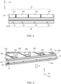
- FIG. 2 illustrates a schematic top view of an embodiment of the battery bracket according to the invention.
- the battery bracket 10 is shown in a state being mounted to the battery pack case 20 for a battery pack (not shown). Only a part of the battery pack case 20 is shown in Fig. 2 .
- the battery bracket 10 extends linearly along the y-direction of the coordinate system. In the top view, only the outer structure 12 of the battery bracket 10 is visible.
- a plurality of through-holes 40 is provided in the end of the battery bracket 10 depicted as its bottom end in the view of Fig. 2 .
- the bottom end of the battery bracket 10 as illustrated in Fig. 2 corresponds to the right end of the battery bracket 10 as shown in Fig. 1 .
- the plurality of through-holes 40 provides a means for mounting the battery bracket 10 into a vehicle (not shown).
- the plurality of through-holes 40 is arranged as a series of through-holes 41, 42, 43, and 44 stringed along a direction parallel to the y-axis.
- Each of the through-holes 41, 42, 43, 44 is arranged in the void portion V of the battery bracket 10 (see Fig. 1 ) such that the shape of the inner structure 14 is not affected by pins, screws, or other means used for mounting the battery bracket 10 into a vehicle.
- the battery bracket 10 is fixed to the outer layer 24 covering the outer side face 22 of the battery pack case 20 (see Fig. 1 ). As shown in Fig. 1 , the outer layer 24 is reverted around the lower and upper edges of the outer side face 22 so as to cover at least a part of the lower and upper side faces of the battery pack case 20.
- FIG. 3 illustrates a schematic three-dimensional view of an embodiment of the battery bracket 10 according to the invention in a state mounted to the outer side face 22 of a battery pack case 20.
- the battery pack case 20 Opposite to the outer side face 22, to which the battery bracket 10 is affixed, the battery pack case 20 is confined by a rear side 22a. To the right, the battery pack case 20 is confined by a right side face 22c.
- the left side of battery pack case 20 is not shown in Fig. 3 . Instead, the structure of the battery pack case 20 as described in the following could be continued to the left side.
- the battery pack case 20 may be subdivided into a plurality of compartments 261, 262, 263, 264 separated from each other by separators 281, 282, 283.
- the separators 281, 282, 283 may also act as an inner stiffness structure for the battery pack case 20.
- Each of the compartments 261, 262, 263, 264 is configured for accommodating a stack of battery cells (not shown).
- the compartments 261, 262, 263, 264 are aligned or stacked one after the other along the y-direction.
- the outer side face 22 of the battery pack case 20 is then formed by the entirety of the respective outer side faces of the compartments 261, 262, 263, 264 facing into the x-direction (only a side face 221 of the leftmost compartment 261 is visible in Fig. 3 ).
- the outer layer 24 may thus be correspondingly subdivided into a plurality of layer-stripes 241, 242, 243, 244 as shown in Fig. 2 .
- the layer-stripes may also act as a thermal interface to the battery module or the corresponding battery cell.
- Each of the layer-stripes 241, 242, 243, 244 covers a corresponding area of the outer side face 22 in the region of the respective compartment 261, 262, 263, 264.
- Adjacent layer-stripes 241, 242, 243, 244 may the separated from each other in the regions of the separators 281, 282, 283.
- the separators 281, 282, 283 not only separate the individual compartments 261, 262, 263, 264 from each other but also act an inner stiffener structure within the battery pack case 20, i. e., the separators 281, 282, 283 are able to absorb mechanical energy exerted onto the outer side face 22 (or the rear side 22a). This stabilizes the battery pack case 20 and in particular plays a role in the distribution of external forces acting on the battery pack case 20 via the transmission through the battery bracket 10. This will be explained in further detail below with reference to Fig. 4 .
- the outer side face 22 of the battery pack case 20 (only the side face 221 of the leftmost compartment 261 is visible in Fig. 3 , which forms a part of the outer side face 22 as described above) is covered by the outer layer 24 made of steel.
- the outer structure 12 is affixed (preferably by welding) to the outer layer 24 covering the outer side face 22 as described already above in the context of Fig. 1 .
- the inner structure 14 is affixed (preferably by welding) to the outer layer 24 is also described with reference to Fig. 1 .
- FIG 4 the deformation of an embodiment of the battery bracket 10 according to the invention, when an external mechanical force is applied to the battery bracket 10, is schematically illustrated by a three-dimensional simulation (FEA calculations) of the battery bracket 10 and (a portion of) the battery pack case 20, to which the battery bracket 10 is attached in a manner as described before with reference to Figs. 1 - 3 .
- the inner and outer structures 12, 14 of the battery bracket 10 as well as the outer side face 22 of the battery pack case 20 extend linearly along the y-direction.
- the internal strains evolving within the cold roll-formed steel sheets of the outer and inner structures 12, 14 of the battery bracket 10 as well as within the outer side face 22 of the battery pack case 20 upon the impact of an external force are indicated by shades of a gray scale.
- a darker shade of gray denotes a higher strain compared to a lighter shade of gray.
- no units are provided in Fig. 4 with regard to the gray scale.
- the filled portion F and the void portion V of the battery bracket 10 are indicated by curly brackets, which refer to the intersectional cut being visible at the front of the three-dimensional illustrations, these intersectional cuts taken through a plane parallel to the x-z-plane of the coordinate system.
- the source of the external mechanical force i. e., the foreign impactor
- the source of the external mechanical force is indicated by a geometrically simple external structure S shaped essentially like a part of a curved surface area of cylinder with a symmetry axis extending parallel to the z-direction.
- the external structure S pushes, by its curved surface area, into the void portion V of the outer structure 12 of battery bracket 10 in a direction against the x-direction of the coordinate system. Due to these pushes, the battery bracket 10 becomes deformed.
- the deformation may be depicted in an exaggerated manner in comparison to typical situations in reality for the sake of illustration.
- the overall rigidity of the filled portion F is higher than the overall rigidity of the void portion V.
- the mechanical function of the shown assembly can be described as follows: The outer structure 12 must resist the force of the foreign impactor (here: the external structure S) and at the same time guide (distribute) the force of the foreign impactor onto the stiffness structure of the battery pack case 20. This is realized by a first crush zone corresponding to the void portion V and second crush zone corresponding to the filled portion F.
- Crush zones generally are zones that may deform upon an impact exerted by an external force. To deform the crush zones, at least a part of the energy provided by the external force is absorbed and distributed within the structures forming the crush zones. The energy transmitted to the battery pack case 20 is then reduced by the amount of energy absorbed by the crush zones or, in other words, the impact of the external force onto the battery pack case 20 is alleviated by the crush zones.
- the battery bracket 10 Due to the lower rigidity of the battery bracket 10 in the first crush zone, the battery bracket 10 becomes easier deformed upon impact of an external force in comparison to the second crush zone. Thus, a main part of an external force is alleviated by the first crush zone. A remainder of the force, however, is transmitted to the second crush zone with higher rigidity.
- the second crush zone can also be deformed, but its main purpose is to distribute the (remainder of the) external force on the outer side face 22 and thus decrease, on the outer side face 22 of the battery pack case 20, the punctual impact (local impact onto a relatively small region of the outer side face 22) of the external force.
- the mechanical energy provided by the external force can be further absorbed by internal state of the structures of the battery pack case 20, as, for example, provided by the separators 281, 282, 283 (each of them arranged in parallel to the x-z-plane of the coordinate system) as described above with reference to Fig. 3 .
- the inner structure 14 provides support to the outer structure 12.
- the inner structure 14 must be configured to stabilize the walls of the outer structure 12 (i. e., the internal walls of the cavity C in the region of the filled portion F) and, moreover, should take a role to guide (distribute), via the region of the filled portion (i. e., via the second crush zone), the impactor force to other stiffness structure of battery pack case 20, thereby reducing the surface pressure on the outer side face 22 of the battery pack case 20.
- the geometry of the internal structure must be designed as crush folding suitable geometry, i.
- the material grade of the inner structure 14 must be defined adequately (see above).
- the first and second crush zones provide a progressive resistance behavior of the battery bracket 10 against an external force such as the force exerted by the external structure S.
- Fig. 4A and Fig. 4B are distinguished in that the force applied to the battery bracket 10 by the external structure S is less in the situation depicted in Fig. 4A in comparison to the situation depicted in Fig. 4B .
- the absolute values of the applied forces are not relevant in the present context.
- the void portion V of the battery bracket 10 is affected by the force exerted by the external structure S.
- the filled portion F i. e, the second crush zone
- the internal strain present in the outer structure 12 in the region of the void portion V is large in comparison to the internal strain present in the outer structure 12 in the region of the filled portion F and in the inner structure 14, as can be taken by the different shades of gray.
- the impact applied by the external structure S towards the battery pack case 20 is almost completely absorbed by the first crush zone.
- the external structure S has been penetrated into the battery bracket 10 so far that also the inner structure 14 becomes quenched by the external structure S. Accordingly, the inner structure 14 is also affected by the impact caused by the external structure S, resulting in a deformation of the alert structure 14. In other words, the impact towards the outer side face 22 of the battery pack case 20 becomes alleviated by both, the first crush zone and the second.
Landscapes
- Engineering & Computer Science (AREA)
- Chemical & Material Sciences (AREA)
- Chemical Kinetics & Catalysis (AREA)
- General Chemical & Material Sciences (AREA)
- Electrochemistry (AREA)
- Transportation (AREA)
- Mechanical Engineering (AREA)
- Aviation & Aerospace Engineering (AREA)
- Combustion & Propulsion (AREA)
- Life Sciences & Earth Sciences (AREA)
- Sustainable Development (AREA)
- Sustainable Energy (AREA)
- Power Engineering (AREA)
- Battery Mounting, Suspending (AREA)
Priority Applications (6)
| Application Number | Priority Date | Filing Date | Title |
|---|---|---|---|
| HUE21210596A HUE070679T2 (hu) | 2021-11-25 | 2021-11-25 | Két félgyártmányból álló, oldalsó akkumulátortartó konzol |
| PL21210596.9T PL4187701T3 (pl) | 2021-11-25 | 2021-11-25 | Boczny wspornik akumulatora zawierający dwa półprodukty |
| EP21210596.9A EP4187701B1 (en) | 2021-11-25 | 2021-11-25 | Lateral battery bracket comprising two semi products |
| US18/058,661 US12341211B2 (en) | 2021-11-25 | 2022-11-23 | Lateral battery bracket comprising two semi products |
| KR1020220158664A KR20230077683A (ko) | 2021-11-25 | 2022-11-23 | 전지 브래킷, 전지 브래킷을 포함하는 전지 팩 및 전지 팩을 포함하는 차량 |
| CN202211490748.5A CN116169417A (zh) | 2021-11-25 | 2022-11-25 | 电池支架、包括电池支架的电池组及包括电池组的车辆 |
Applications Claiming Priority (1)
| Application Number | Priority Date | Filing Date | Title |
|---|---|---|---|
| EP21210596.9A EP4187701B1 (en) | 2021-11-25 | 2021-11-25 | Lateral battery bracket comprising two semi products |
Publications (2)
| Publication Number | Publication Date |
|---|---|
| EP4187701A1 EP4187701A1 (en) | 2023-05-31 |
| EP4187701B1 true EP4187701B1 (en) | 2025-02-12 |
Family
ID=78789918
Family Applications (1)
| Application Number | Title | Priority Date | Filing Date |
|---|---|---|---|
| EP21210596.9A Active EP4187701B1 (en) | 2021-11-25 | 2021-11-25 | Lateral battery bracket comprising two semi products |
Country Status (4)
| Country | Link |
|---|---|
| EP (1) | EP4187701B1 (pl) |
| KR (1) | KR20230077683A (pl) |
| HU (1) | HUE070679T2 (pl) |
| PL (1) | PL4187701T3 (pl) |
Family Cites Families (5)
| Publication number | Priority date | Publication date | Assignee | Title |
|---|---|---|---|---|
| JP3918293B2 (ja) * | 1998-04-10 | 2007-05-23 | 日産自動車株式会社 | 車両用バッテリーの固定構造 |
| JP6475270B2 (ja) * | 2017-01-20 | 2019-02-27 | 株式会社Subaru | 自動車車両 |
| JP6655638B2 (ja) * | 2018-02-15 | 2020-02-26 | 本田技研工業株式会社 | 車体構造 |
| US10494030B1 (en) * | 2018-08-20 | 2019-12-03 | Ford Global Technologies, Llc | Collapsible battery pack support assembly and supporting method |
| DE102020103240B3 (de) * | 2020-02-09 | 2021-06-24 | Ford Global Technologies Llc | Befestigungsvorrichtung einer zur Traktion eines Fahrzeugs, bevorzugt Elektrofahrzeugs dienenden elektrischen Energiequelle |
-
2021
- 2021-11-25 HU HUE21210596A patent/HUE070679T2/hu unknown
- 2021-11-25 PL PL21210596.9T patent/PL4187701T3/pl unknown
- 2021-11-25 EP EP21210596.9A patent/EP4187701B1/en active Active
-
2022
- 2022-11-23 KR KR1020220158664A patent/KR20230077683A/ko active Pending
Also Published As
| Publication number | Publication date |
|---|---|
| KR20230077683A (ko) | 2023-06-01 |
| EP4187701A1 (en) | 2023-05-31 |
| PL4187701T3 (pl) | 2025-04-28 |
| HUE070679T2 (hu) | 2025-06-28 |
Similar Documents
| Publication | Publication Date | Title |
|---|---|---|
| US10720620B1 (en) | High voltage battery pack mounting systems for providing load path management during impact loading events | |
| US12036878B2 (en) | Power supply device, vehicle having power supply device, and power storage device | |
| US20220045397A1 (en) | Battery pack | |
| US20250286184A1 (en) | Lower box body of battery, battery, and electric apparatus | |
| US20250192304A1 (en) | Structural plate members for absorbing and distributing energy within traction battery packs | |
| JP7033255B2 (ja) | 組電池 | |
| EP4636875A1 (en) | Battery pack and method of manufacturing the same | |
| US20250309434A1 (en) | Battery module, and battery pack and vehicle including the same | |
| KR101381098B1 (ko) | 저속 충격 하중에 대한 손상성 및 수리성을 향상한 전기자동차용 배터리 | |
| CN219584286U (zh) | 车身结构和车辆 | |
| SE2150526A1 (en) | Battery Module, Battery Pack, and Vehicle | |
| KR20220099369A (ko) | 배터리 모듈 외곽 하우징 | |
| EP4187701B1 (en) | Lateral battery bracket comprising two semi products | |
| EP4037083B1 (en) | Protection assembly and battery housing comprising the same | |
| US12341211B2 (en) | Lateral battery bracket comprising two semi products | |
| US12134311B2 (en) | Protection assembly and battery housing comprising the same | |
| CN218101551U (zh) | 电池及用电装置 | |
| JP7474229B2 (ja) | 移動体 | |
| US10629877B2 (en) | Battery pack | |
| KR20140003909A (ko) | 저속 충격 하중에 대한 손상성 및 수리성을 향상한 전기자동차용 배터리 | |
| CN223864676U (zh) | 电池装置和车辆 | |
| CN220884027U (zh) | 车体的化学仓、车体和车辆 | |
| CN223206370U (zh) | 电池装置及用电设备 | |
| JP7104754B2 (ja) | 蓄電モジュール | |
| CN222705633U (zh) | 电池及用电设备 |
Legal Events
| Date | Code | Title | Description |
|---|---|---|---|
| PUAI | Public reference made under article 153(3) epc to a published international application that has entered the european phase |
Free format text: ORIGINAL CODE: 0009012 |
|
| STAA | Information on the status of an ep patent application or granted ep patent |
Free format text: STATUS: REQUEST FOR EXAMINATION WAS MADE |
|
| 17P | Request for examination filed |
Effective date: 20221118 |
|
| AK | Designated contracting states |
Kind code of ref document: A1 Designated state(s): AL AT BE BG CH CY CZ DE DK EE ES FI FR GB GR HR HU IE IS IT LI LT LU LV MC MK MT NL NO PL PT RO RS SE SI SK SM TR |
|
| GRAP | Despatch of communication of intention to grant a patent |
Free format text: ORIGINAL CODE: EPIDOSNIGR1 |
|
| STAA | Information on the status of an ep patent application or granted ep patent |
Free format text: STATUS: GRANT OF PATENT IS INTENDED |
|
| RIC1 | Information provided on ipc code assigned before grant |
Ipc: B60L 50/64 20190101ALI20240822BHEP Ipc: H01M 50/249 20210101AFI20240822BHEP |
|
| INTG | Intention to grant announced |
Effective date: 20240906 |
|
| GRAS | Grant fee paid |
Free format text: ORIGINAL CODE: EPIDOSNIGR3 |
|
| GRAA | (expected) grant |
Free format text: ORIGINAL CODE: 0009210 |
|
| STAA | Information on the status of an ep patent application or granted ep patent |
Free format text: STATUS: THE PATENT HAS BEEN GRANTED |
|
| AK | Designated contracting states |
Kind code of ref document: B1 Designated state(s): AL AT BE BG CH CY CZ DE DK EE ES FI FR GB GR HR HU IE IS IT LI LT LU LV MC MK MT NL NO PL PT RO RS SE SI SK SM TR |
|
| REG | Reference to a national code |
Ref country code: GB Ref legal event code: FG4D |
|
| REG | Reference to a national code |
Ref country code: CH Ref legal event code: EP |
|
| REG | Reference to a national code |
Ref country code: DE Ref legal event code: R096 Ref document number: 602021025936 Country of ref document: DE |
|
| REG | Reference to a national code |
Ref country code: IE Ref legal event code: FG4D |
|
| REG | Reference to a national code |
Ref country code: SE Ref legal event code: TRGR |
|
| REG | Reference to a national code |
Ref country code: NL Ref legal event code: MP Effective date: 20250212 |
|
| REG | Reference to a national code |
Ref country code: HU Ref legal event code: AG4A Ref document number: E070679 Country of ref document: HU |
|
| PG25 | Lapsed in a contracting state [announced via postgrant information from national office to epo] |
Ref country code: RS Free format text: LAPSE BECAUSE OF FAILURE TO SUBMIT A TRANSLATION OF THE DESCRIPTION OR TO PAY THE FEE WITHIN THE PRESCRIBED TIME-LIMIT Effective date: 20250512 |
|
| PG25 | Lapsed in a contracting state [announced via postgrant information from national office to epo] |
Ref country code: FI Free format text: LAPSE BECAUSE OF FAILURE TO SUBMIT A TRANSLATION OF THE DESCRIPTION OR TO PAY THE FEE WITHIN THE PRESCRIBED TIME-LIMIT Effective date: 20250212 |
|
| PG25 | Lapsed in a contracting state [announced via postgrant information from national office to epo] |
Ref country code: ES Free format text: LAPSE BECAUSE OF FAILURE TO SUBMIT A TRANSLATION OF THE DESCRIPTION OR TO PAY THE FEE WITHIN THE PRESCRIBED TIME-LIMIT Effective date: 20250212 |
|
| REG | Reference to a national code |
Ref country code: LT Ref legal event code: MG9D |
|
| PG25 | Lapsed in a contracting state [announced via postgrant information from national office to epo] |
Ref country code: NO Free format text: LAPSE BECAUSE OF FAILURE TO SUBMIT A TRANSLATION OF THE DESCRIPTION OR TO PAY THE FEE WITHIN THE PRESCRIBED TIME-LIMIT Effective date: 20250512 Ref country code: IS Free format text: LAPSE BECAUSE OF FAILURE TO SUBMIT A TRANSLATION OF THE DESCRIPTION OR TO PAY THE FEE WITHIN THE PRESCRIBED TIME-LIMIT Effective date: 20250612 |
|
| PG25 | Lapsed in a contracting state [announced via postgrant information from national office to epo] |
Ref country code: NL Free format text: LAPSE BECAUSE OF FAILURE TO SUBMIT A TRANSLATION OF THE DESCRIPTION OR TO PAY THE FEE WITHIN THE PRESCRIBED TIME-LIMIT Effective date: 20250212 |
|
| PG25 | Lapsed in a contracting state [announced via postgrant information from national office to epo] |
Ref country code: HR Free format text: LAPSE BECAUSE OF FAILURE TO SUBMIT A TRANSLATION OF THE DESCRIPTION OR TO PAY THE FEE WITHIN THE PRESCRIBED TIME-LIMIT Effective date: 20250212 |
|
| PG25 | Lapsed in a contracting state [announced via postgrant information from national office to epo] |
Ref country code: LV Free format text: LAPSE BECAUSE OF FAILURE TO SUBMIT A TRANSLATION OF THE DESCRIPTION OR TO PAY THE FEE WITHIN THE PRESCRIBED TIME-LIMIT Effective date: 20250212 Ref country code: PT Free format text: LAPSE BECAUSE OF FAILURE TO SUBMIT A TRANSLATION OF THE DESCRIPTION OR TO PAY THE FEE WITHIN THE PRESCRIBED TIME-LIMIT Effective date: 20250612 |
|
| PG25 | Lapsed in a contracting state [announced via postgrant information from national office to epo] |
Ref country code: GR Free format text: LAPSE BECAUSE OF FAILURE TO SUBMIT A TRANSLATION OF THE DESCRIPTION OR TO PAY THE FEE WITHIN THE PRESCRIBED TIME-LIMIT Effective date: 20250513 Ref country code: BG Free format text: LAPSE BECAUSE OF FAILURE TO SUBMIT A TRANSLATION OF THE DESCRIPTION OR TO PAY THE FEE WITHIN THE PRESCRIBED TIME-LIMIT Effective date: 20250212 |
|
| PG25 | Lapsed in a contracting state [announced via postgrant information from national office to epo] |
Ref country code: SM Free format text: LAPSE BECAUSE OF FAILURE TO SUBMIT A TRANSLATION OF THE DESCRIPTION OR TO PAY THE FEE WITHIN THE PRESCRIBED TIME-LIMIT Effective date: 20250212 |
|
| PG25 | Lapsed in a contracting state [announced via postgrant information from national office to epo] |
Ref country code: DK Free format text: LAPSE BECAUSE OF FAILURE TO SUBMIT A TRANSLATION OF THE DESCRIPTION OR TO PAY THE FEE WITHIN THE PRESCRIBED TIME-LIMIT Effective date: 20250212 |
|
| PG25 | Lapsed in a contracting state [announced via postgrant information from national office to epo] |
Ref country code: IT Free format text: LAPSE BECAUSE OF FAILURE TO SUBMIT A TRANSLATION OF THE DESCRIPTION OR TO PAY THE FEE WITHIN THE PRESCRIBED TIME-LIMIT Effective date: 20250212 |
|
| PG25 | Lapsed in a contracting state [announced via postgrant information from national office to epo] |
Ref country code: EE Free format text: LAPSE BECAUSE OF FAILURE TO SUBMIT A TRANSLATION OF THE DESCRIPTION OR TO PAY THE FEE WITHIN THE PRESCRIBED TIME-LIMIT Effective date: 20250212 Ref country code: CZ Free format text: LAPSE BECAUSE OF FAILURE TO SUBMIT A TRANSLATION OF THE DESCRIPTION OR TO PAY THE FEE WITHIN THE PRESCRIBED TIME-LIMIT Effective date: 20250212 |
|
| PG25 | Lapsed in a contracting state [announced via postgrant information from national office to epo] |
Ref country code: RO Free format text: LAPSE BECAUSE OF FAILURE TO SUBMIT A TRANSLATION OF THE DESCRIPTION OR TO PAY THE FEE WITHIN THE PRESCRIBED TIME-LIMIT Effective date: 20250212 |
|
| PG25 | Lapsed in a contracting state [announced via postgrant information from national office to epo] |
Ref country code: SK Free format text: LAPSE BECAUSE OF FAILURE TO SUBMIT A TRANSLATION OF THE DESCRIPTION OR TO PAY THE FEE WITHIN THE PRESCRIBED TIME-LIMIT Effective date: 20250212 |
|
| REG | Reference to a national code |
Ref country code: DE Ref legal event code: R097 Ref document number: 602021025936 Country of ref document: DE |
|
| PGFP | Annual fee paid to national office [announced via postgrant information from national office to epo] |
Ref country code: HU Payment date: 20251127 Year of fee payment: 5 |
|
| PLBE | No opposition filed within time limit |
Free format text: ORIGINAL CODE: 0009261 |
|
| STAA | Information on the status of an ep patent application or granted ep patent |
Free format text: STATUS: NO OPPOSITION FILED WITHIN TIME LIMIT |
|
| PGFP | Annual fee paid to national office [announced via postgrant information from national office to epo] |
Ref country code: DE Payment date: 20251104 Year of fee payment: 5 |
|
| PGFP | Annual fee paid to national office [announced via postgrant information from national office to epo] |
Ref country code: GB Payment date: 20251030 Year of fee payment: 5 |
|
| PGFP | Annual fee paid to national office [announced via postgrant information from national office to epo] |
Ref country code: AT Payment date: 20260113 Year of fee payment: 5 |
|
| PGFP | Annual fee paid to national office [announced via postgrant information from national office to epo] |
Ref country code: FR Payment date: 20251117 Year of fee payment: 5 |
|
| 26N | No opposition filed |
Effective date: 20251113 |
|
| PGFP | Annual fee paid to national office [announced via postgrant information from national office to epo] |
Ref country code: PL Payment date: 20251117 Year of fee payment: 5 |