EP4187697A2 - Anordnung für ein fahrzeug mit einer vielzahl von batterien und einem evakuierungssystem - Google Patents
Anordnung für ein fahrzeug mit einer vielzahl von batterien und einem evakuierungssystem Download PDFInfo
- Publication number
- EP4187697A2 EP4187697A2 EP22209390.8A EP22209390A EP4187697A2 EP 4187697 A2 EP4187697 A2 EP 4187697A2 EP 22209390 A EP22209390 A EP 22209390A EP 4187697 A2 EP4187697 A2 EP 4187697A2
- Authority
- EP
- European Patent Office
- Prior art keywords
- enclosure
- assembly
- housing
- pipe
- damping
- Prior art date
- Legal status (The legal status is an assumption and is not a legal conclusion. Google has not performed a legal analysis and makes no representation as to the accuracy of the status listed.)
- Pending
Links
Images


Classifications
-
- H—ELECTRICITY
- H02—GENERATION; CONVERSION OR DISTRIBUTION OF ELECTRIC POWER
- H02J—ELECTRIC POWER NETWORKS; CIRCUIT ARRANGEMENTS OR SYSTEMS FOR SUPPLYING OR DISTRIBUTING ELECTRIC POWER; SYSTEMS FOR STORING ELECTRIC ENERGY
- H02J7/00—Circuit arrangements for charging or discharging batteries or for supplying loads from batteries
- H02J7/855—Circuit arrangements for charging or discharging batteries or for supplying loads from batteries with circuits adapted for supplying loads from the battery
-
- B—PERFORMING OPERATIONS; TRANSPORTING
- B60—VEHICLES IN GENERAL
- B60R—VEHICLES, VEHICLE FITTINGS, OR VEHICLE PARTS, NOT OTHERWISE PROVIDED FOR
- B60R16/00—Electric or fluid circuits specially adapted for vehicles and not otherwise provided for; Arrangement of elements of electric or fluid circuits specially adapted for vehicles and not otherwise provided for
- B60R16/02—Electric or fluid circuits specially adapted for vehicles and not otherwise provided for; Arrangement of elements of electric or fluid circuits specially adapted for vehicles and not otherwise provided for electric constitutive elements
- B60R16/04—Arrangement of batteries
-
- H—ELECTRICITY
- H01—ELECTRIC ELEMENTS
- H01M—PROCESSES OR MEANS, e.g. BATTERIES, FOR THE DIRECT CONVERSION OF CHEMICAL ENERGY INTO ELECTRICAL ENERGY
- H01M50/00—Constructional details or processes of manufacture of the non-active parts of electrochemical cells other than fuel cells, e.g. hybrid cells
- H01M50/20—Mountings; Secondary casings or frames; Racks, modules or packs; Suspension devices; Shock absorbers; Transport or carrying devices; Holders
- H01M50/204—Racks, modules or packs for multiple batteries or multiple cells
-
- B—PERFORMING OPERATIONS; TRANSPORTING
- B64—AIRCRAFT; AVIATION; COSMONAUTICS
- B64D—EQUIPMENT FOR FITTING IN OR TO AIRCRAFT; FLIGHT SUITS; PARACHUTES; ARRANGEMENT OR MOUNTING OF POWER PLANTS OR PROPULSION TRANSMISSIONS IN AIRCRAFT
- B64D47/00—Equipment not otherwise provided for
-
- H—ELECTRICITY
- H01—ELECTRIC ELEMENTS
- H01M—PROCESSES OR MEANS, e.g. BATTERIES, FOR THE DIRECT CONVERSION OF CHEMICAL ENERGY INTO ELECTRICAL ENERGY
- H01M10/00—Secondary cells; Manufacture thereof
- H01M10/42—Methods or arrangements for servicing or maintenance of secondary cells or secondary half-cells
- H01M10/425—Structural combination with electronic components, e.g. electronic circuits integrated to the outside of the casing
- H01M10/4257—Smart batteries, e.g. electronic circuits inside the housing of the cells or batteries
-
- H—ELECTRICITY
- H01—ELECTRIC ELEMENTS
- H01M—PROCESSES OR MEANS, e.g. BATTERIES, FOR THE DIRECT CONVERSION OF CHEMICAL ENERGY INTO ELECTRICAL ENERGY
- H01M10/00—Secondary cells; Manufacture thereof
- H01M10/42—Methods or arrangements for servicing or maintenance of secondary cells or secondary half-cells
- H01M10/52—Removing gases inside the secondary cell, e.g. by absorption
-
- H—ELECTRICITY
- H01—ELECTRIC ELEMENTS
- H01M—PROCESSES OR MEANS, e.g. BATTERIES, FOR THE DIRECT CONVERSION OF CHEMICAL ENERGY INTO ELECTRICAL ENERGY
- H01M50/00—Constructional details or processes of manufacture of the non-active parts of electrochemical cells other than fuel cells, e.g. hybrid cells
- H01M50/20—Mountings; Secondary casings or frames; Racks, modules or packs; Suspension devices; Shock absorbers; Transport or carrying devices; Holders
- H01M50/249—Mountings; Secondary casings or frames; Racks, modules or packs; Suspension devices; Shock absorbers; Transport or carrying devices; Holders specially adapted for aircraft or vehicles, e.g. cars or trains
-
- H—ELECTRICITY
- H01—ELECTRIC ELEMENTS
- H01M—PROCESSES OR MEANS, e.g. BATTERIES, FOR THE DIRECT CONVERSION OF CHEMICAL ENERGY INTO ELECTRICAL ENERGY
- H01M50/00—Constructional details or processes of manufacture of the non-active parts of electrochemical cells other than fuel cells, e.g. hybrid cells
- H01M50/30—Arrangements for facilitating escape of gases
-
- H—ELECTRICITY
- H01—ELECTRIC ELEMENTS
- H01M—PROCESSES OR MEANS, e.g. BATTERIES, FOR THE DIRECT CONVERSION OF CHEMICAL ENERGY INTO ELECTRICAL ENERGY
- H01M50/00—Constructional details or processes of manufacture of the non-active parts of electrochemical cells other than fuel cells, e.g. hybrid cells
- H01M50/30—Arrangements for facilitating escape of gases
- H01M50/317—Re-sealable arrangements
-
- H—ELECTRICITY
- H01—ELECTRIC ELEMENTS
- H01M—PROCESSES OR MEANS, e.g. BATTERIES, FOR THE DIRECT CONVERSION OF CHEMICAL ENERGY INTO ELECTRICAL ENERGY
- H01M50/00—Constructional details or processes of manufacture of the non-active parts of electrochemical cells other than fuel cells, e.g. hybrid cells
- H01M50/30—Arrangements for facilitating escape of gases
- H01M50/317—Re-sealable arrangements
- H01M50/325—Re-sealable arrangements comprising deformable valve members, e.g. elastic or flexible valve members
-
- H—ELECTRICITY
- H01—ELECTRIC ELEMENTS
- H01M—PROCESSES OR MEANS, e.g. BATTERIES, FOR THE DIRECT CONVERSION OF CHEMICAL ENERGY INTO ELECTRICAL ENERGY
- H01M50/00—Constructional details or processes of manufacture of the non-active parts of electrochemical cells other than fuel cells, e.g. hybrid cells
- H01M50/30—Arrangements for facilitating escape of gases
- H01M50/342—Non-re-sealable arrangements
- H01M50/3425—Non-re-sealable arrangements in the form of rupturable membranes or weakened parts, e.g. pierced with the aid of a sharp member
-
- H—ELECTRICITY
- H01—ELECTRIC ELEMENTS
- H01M—PROCESSES OR MEANS, e.g. BATTERIES, FOR THE DIRECT CONVERSION OF CHEMICAL ENERGY INTO ELECTRICAL ENERGY
- H01M50/00—Constructional details or processes of manufacture of the non-active parts of electrochemical cells other than fuel cells, e.g. hybrid cells
- H01M50/30—Arrangements for facilitating escape of gases
- H01M50/35—Gas exhaust passages comprising elongated, tortuous or labyrinth-shaped exhaust passages
-
- H—ELECTRICITY
- H01—ELECTRIC ELEMENTS
- H01M—PROCESSES OR MEANS, e.g. BATTERIES, FOR THE DIRECT CONVERSION OF CHEMICAL ENERGY INTO ELECTRICAL ENERGY
- H01M50/00—Constructional details or processes of manufacture of the non-active parts of electrochemical cells other than fuel cells, e.g. hybrid cells
- H01M50/30—Arrangements for facilitating escape of gases
- H01M50/35—Gas exhaust passages comprising elongated, tortuous or labyrinth-shaped exhaust passages
- H01M50/358—External gas exhaust passages located on the battery cover or case
-
- H—ELECTRICITY
- H01—ELECTRIC ELEMENTS
- H01M—PROCESSES OR MEANS, e.g. BATTERIES, FOR THE DIRECT CONVERSION OF CHEMICAL ENERGY INTO ELECTRICAL ENERGY
- H01M50/00—Constructional details or processes of manufacture of the non-active parts of electrochemical cells other than fuel cells, e.g. hybrid cells
- H01M50/30—Arrangements for facilitating escape of gases
- H01M50/375—Vent means sensitive to or responsive to temperature
-
- B—PERFORMING OPERATIONS; TRANSPORTING
- B64—AIRCRAFT; AVIATION; COSMONAUTICS
- B64D—EQUIPMENT FOR FITTING IN OR TO AIRCRAFT; FLIGHT SUITS; PARACHUTES; ARRANGEMENT OR MOUNTING OF POWER PLANTS OR PROPULSION TRANSMISSIONS IN AIRCRAFT
- B64D2221/00—Electric power distribution systems onboard aircraft
-
- H—ELECTRICITY
- H01—ELECTRIC ELEMENTS
- H01M—PROCESSES OR MEANS, e.g. BATTERIES, FOR THE DIRECT CONVERSION OF CHEMICAL ENERGY INTO ELECTRICAL ENERGY
- H01M2200/00—Safety devices for primary or secondary batteries
- H01M2200/10—Temperature sensitive devices
-
- H—ELECTRICITY
- H01—ELECTRIC ELEMENTS
- H01M—PROCESSES OR MEANS, e.g. BATTERIES, FOR THE DIRECT CONVERSION OF CHEMICAL ENERGY INTO ELECTRICAL ENERGY
- H01M2200/00—Safety devices for primary or secondary batteries
- H01M2200/20—Pressure-sensitive devices
-
- H—ELECTRICITY
- H01—ELECTRIC ELEMENTS
- H01M—PROCESSES OR MEANS, e.g. BATTERIES, FOR THE DIRECT CONVERSION OF CHEMICAL ENERGY INTO ELECTRICAL ENERGY
- H01M2220/00—Batteries for particular applications
- H01M2220/20—Batteries in motive systems, e.g. vehicle, ship, plane
-
- Y—GENERAL TAGGING OF NEW TECHNOLOGICAL DEVELOPMENTS; GENERAL TAGGING OF CROSS-SECTIONAL TECHNOLOGIES SPANNING OVER SEVERAL SECTIONS OF THE IPC; TECHNICAL SUBJECTS COVERED BY FORMER USPC CROSS-REFERENCE ART COLLECTIONS [XRACs] AND DIGESTS
- Y02—TECHNOLOGIES OR APPLICATIONS FOR MITIGATION OR ADAPTATION AGAINST CLIMATE CHANGE
- Y02E—REDUCTION OF GREENHOUSE GAS [GHG] EMISSIONS, RELATED TO ENERGY GENERATION, TRANSMISSION OR DISTRIBUTION
- Y02E60/00—Enabling technologies; Technologies with a potential or indirect contribution to GHG emissions mitigation
- Y02E60/10—Energy storage using batteries
Definitions
- the present invention relates to an assembly for a vehicle, in particular an aircraft, wherein said assembly comprises a plurality of batteries and an evacuation system arranged to evacuate fluids from the vehicle.
- the invention also relates to a vehicle equipped with such an assembly.
- An aircraft conventionally comprises batteries, in particular lithium-ion batteries, in order to ensure the power supply of the devices present in the aircraft.
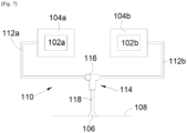
- FIG. 7 shows a state of the art installation mode.
- the installation comprises two battery blocks 102a-b, each consisting of at least one battery, and each battery block 102a-b is enclosed in an enclosure 104a-b delimited by a wall and ensuring the confinement of the battery block 102a-b in the event of a fault on one of the batteries of said battery pack 102a-b.
- the aircraft When a battery deteriorates, gases can spread in the enclosure 104a-b.
- the aircraft To evacuate these gases, the aircraft includes an evacuation system 110 which ensures the evacuation of the gases to the outside of the aircraft.
- the evacuation system 110 is provided for two battery packs 102a-b and comprises an outlet port 106 which is arranged in the skin 108 of the aircraft, a T-fitting 114 and, for each battery pack 102a-b, a evacuation pipe 112a-b fluidly connected between the associated enclosure 104a-b and one of the two inlets of the T-piece 114.
- Evacuation system 110 also includes an outlet line 118 fluidly connected between an outlet of tee fitting 114 and outlet port 106.
- the T-piece 114 is equipped with a non-return valve 116, here in the form of a ball which, depending on the pressure in each evacuation pipe 112a-b moves between the two inlets of the T-piece 114 in order to block them alternately and thus allow the passage of gas from an evacuation pipe 112a-b towards the outlet orifice 106.
- a non-return valve 116 here in the form of a ball which, depending on the pressure in each evacuation pipe 112a-b moves between the two inlets of the T-piece 114 in order to block them alternately and thus allow the passage of gas from an evacuation pipe 112a-b towards the outlet orifice 106.
- the pressurized gas flows into the evacuation pipe 112a and pushes the ball against the other evacuation pipe 112b to block it and prevent the flow of the fluid to battery pack 102b.
- the gas then continues its advance through the outlet pipe 118 then the outlet orifice 106.
- lines 112a-b and 118 and tee 114 When a battery deteriorates, it can generate excess pressure which then propagates through lines 112a-b and 118 and tee 114. In order to withstand this excess pressure, lines 112a-b and 118 must be relatively strong. To do this, they are made of metal and the evacuation system 110 is then relatively heavy, which is detrimental from the point of view of consumption for the aircraft.
- An object of the present invention is to provide an assembly for a vehicle, in particular an aircraft, where said assembly comprises a plurality of batteries and an evacuation system arranged to evacuate fluids from the vehicle, and where this evacuation system is lighter than in the case of the state of the art.
- Such an assembly allows, among other things, damping of an overpressure propagating when a battery deteriorates.
- each enclosure comprises a temperature sensor designed to measure the temperature prevailing in said enclosure
- the assembly comprises a reservoir containing an inert gas under pressure, a network of overflow pipes comprising one end fluidly connected to the reservoir through a solenoid valve starting point, for each enclosure, one end fluidly connected to said enclosure through an inlet solenoid valve, and one end fluidly connected to the main pipe through an inlet solenoid valve, and a secondary control unit arranged to receive the measurements transmitted by the temperature sensors and control each solenoid valve in closing or opening.
- the invention also proposes an aircraft comprising an outer skin and at least one assembly according to one of the preceding variants.
- FIG. 1 shows an aircraft 100 which comprises a fuselage 102 having an outer skin 158 and inside which is fixed an assembly 150 according to the invention and which is represented diagrammatically in Fig. 2 for a first embodiment of the invention and to the Fig. 3 for a second embodiment of the invention.
- the invention is more particularly described in the case of an aircraft, it applies to all vehicles transporting battery packs in operation.
- the assembly 150 comprises a plurality of battery packs 152a-c and each battery pack 152a-c is enclosed in a casing 202 ensuring the confinement of the battery pack 152a-c and presenting a face connection 203.
- there are three battery packs 152a-c but the invention can be implemented from at least two battery packs 152a-c.
- Each battery block 152a-c comprises at least one battery, in particular a lithium-ion battery. These batteries are intended to power electrical appliances of the aircraft 100 through electrical conductors, not shown, which run between the batteries and the electrical appliances.
- Assembly 150 also includes an evacuation system 160 which includes an exit port 156 which is arranged through the outer skin 158 of the aircraft 100, a main line 161 fluidly connected to the exit port 156, and, for each housing 202, an exhaust line 162a-c fluidly connected between the connection face 203 of the associated housing 202 and the main line 161 and through the latter to the outlet port 156.
- evacuation system 160 includes an exit port 156 which is arranged through the outer skin 158 of the aircraft 100, a main line 161 fluidly connected to the exit port 156, and, for each housing 202, an exhaust line 162a-c fluidly connected between the connection face 203 of the associated housing 202 and the main line 161 and through the latter to the outlet port 156.
- the pressurized gas flows in the corresponding evacuation pipe 162a-c, to the main pipe 161 and to the outlet orifice 156 .
- an overpressure can be generated. This overpressure can then propagate through the evacuation pipes 162a-c and the main pipe 161.
- the evacuation system 160 comprises at the connection between each connection face 203 and the associated evacuation pipe 162a-c, a damping box 170a-c of a first type and at the connection between the main pipe 161 and the outlet orifice 156, a damping box 170d of a second type.
- Each damping box 170a-d is provided to limit the amplitude of the overpressure which propagates from the box 202 towards the outlet orifice 156 in the evacuation system 160 and it is no longer necessary to provide rigid pipes. and heavy, and lighter pipes can then be used.
- the evacuation system 160 no longer requires the use of a T-piece with a non-return system, which makes it possible to have a simpler installation with less maintenance. It is also possible to fit more than two 152a-c battery packs.
- Each damping box 170a-c of the first type which is at the level of a box 202 makes it possible to attenuate an overpressure which would come out of said box 202 through the connection face 203 to the outlet port 156 and performs the function of a non-return valve in the event that an overpressure comes from another box 202.
- the damping box 170a of the first corresponding type dampens the overpressure which propagates in the corresponding evacuation pipe 162a and the main pipe 161, and if the overpressure which reaches the main pipe 161 is still relatively powerful, the damping box 170d of the second type which is at the level of the outlet orifice 156 dampens the overpressure before it exits to the outside.
- each casing 202 is housed in an enclosure 154a-c delimited by a wall 205 and ensuring the confinement of the battery pack 152a-c enclosed in said casing 202 and of the damping casing 170a- c of the first type associated with said box 202.
- Each evacuation pipe 162a-c is fluidically connected to the connection face 203 of the corresponding housing 202 through the wall 205 of the associated enclosure 154a-c.
- Figs. 4 to 6 show different embodiments of a damping box 370, 470, 570.
- Each Fig. 4 to 6 shows a damping box 370, 470, 570 of the first type which is at the connection between a connection face 303, 403, 503 of the box 302, 402, 502 and the evacuation pipe 312, 412, 512 associated.
- each damping box 370, 470, 570 of the first type can take one or the other of the different forms proposed.
- the casing 302, 402, 502 is fixed to the structure of the aircraft 100.
- the wall 372, 472, 572 of the enclosure 354, 454, 554 is also fixed to the structure of the aircraft 100 by first fixing means 103.
- the box 302, 402, 502 can then be fixed to the wall 372, 472, 572 of the enclosure 354, 454, 554, or directly to the structure of the aircraft 100 by fixing means 101 that said box 302, 402, 502 is housed in an enclosure 354, 454, 554 or not.
- the damping case 370 of the first type comprises a rupture disc 304 constituting the connection face 303 of the case 302 in which the battery pack 352 is enclosed.
- the rupture disc 304 is a wall which is calibrated to rupture when the pressure which is exerted on it reaches a planned threshold and whose mechanical resistance is lower than the mechanical resistance of the other faces of the housing 302 to ensure that the bursting disc 304 will indeed break before said other faces.
- the damping casing 370 of the first type also comprises a bellows 306, a first end of which is fixed in a leaktight manner to the casing 302 around the rupture disc 304 and a second end of which is fixed in a leaktight manner at the inlet of the pipeline. evacuation 312.
- the overpressure will break the rupture disc 304 which will reduce its amplitude and the bellows 306 will inflate under the effect of the overpressure which will also reduce its amplitude.
- the wall 372 of the enclosure 354 encloses the battery unit 352, its casing 302, the inlet of the evacuation pipe 312 and bellows 306.
- the bellows 306 has at each end a skirt 308 which is fixed here by nuts 310 around the skirt 308, respectively to the housing 302 or to the evacuation pipe 312.
- an O-ring 312 is clamped between the skirt 308 and the housing 302 and an O-ring 314 is clamped between the skirt 308 and the exhaust pipe 312.
- the damping housing 470 of the first type comprises a weakened zone 405 made in the connection face 403 of the housing 402 in which the battery block 452 is enclosed.
- the weakened zone 405 is for example an orifice or a pre-cut zone or a zone less thick than the other faces of the housing 402.
- the weakened zone 405 has a mechanical strength lower than the mechanical strength of the other faces of the housing 402.
- the damping box 470 of the first type also comprises a bursting disc 404 which is fixed between the connection face 403 of the box 402 and the inlet of the evacuation pipe 412.
- the damping box 470 includes a frame 413 against which the bursting disc 404 is held.
- the frame 413 is fixed to the structure of the aircraft 100 or to the wall 472 of the enclosure 454 when it is present.
- the damping case 470 of the first type also comprises a first bellows 406a, a first end of which is fixed in a sealed manner to the case 402 around the weakened zone 405 and a second end of which is fixed in a tight manner against a first face of the disc. 404, and a second bellows 406b, a first end of which is sealed against a second face of the rupture disc 404 and a second end of which is sealed to the inlet of the evacuation pipe 412. Both sides of rupture disc 404 are opposite each other.
- the overpressure will break the bursting disc 404 which will attenuate its amplitude and the bellows 406a-b will inflate under the effect of the overpressure which will also attenuate its amplitude.
- each bellows 406 has at each end a skirt which is fixed here by nuts around the skirt, to the bursting disc 404 and to the housing 402 or to the pipe evacuation 412. To complete the seal, an O-ring is tightened between each skirt and the corresponding counterpart.
- the damping box 570 of the first type comprises a weakened zone 505 made in the connection face 503 of the box 502 in which the battery block 552 is enclosed.
- the weakened zone 505 is for example an orifice or a pre-cut zone or a zone less thick than the other faces of the housing 502.
- the weakened zone 505 has a mechanical strength lower than the mechanical strength of the other faces of the housing 502.
- the damping box 570 of the first type also comprises a frame 514 which is fixed in a sealed manner between the evacuation pipe 512 and the connection face 503 of the box 502.
- the frame 514 is fixed and fitted into the inlet of the evacuation pipe 512.
- the frame 514 has a window 516 which passes through it and a shutter 518 which is mounted on the frame 514 and which is movable alternately between a closed position in which the shutter 518 closes the window 516 and an open position in which the shutter 518 does not does not close the window 516.
- the window 516 is opposite the weakened zone 505.
- the damping box 570 also comprises a return means 507, such as for example a spring, which forces the flap 518 into the closed position.
- the force exerted by the return means 507 must be sufficient to maintain the shutter 518 in the closed position but must not impede the opening of the shutter 518 when the pressure exerted on the shutter 518 exceeds a threshold.
- the flap 518 is rotatably mounted, and opens towards the evacuation pipe 512 and the return means 507 is for example a torsion spring.
- the overpressure will push the shutter 518 towards the open position in order to release the window 516 which will attenuate the amplitude of the overpressure.
- the wall 572 of the enclosure 554 encloses the battery unit 552, its casing 502, the inlet of the evacuation pipe 512 , the frame 514 and the flap 518.
- the latter is pierced with a hole 522 whose diameter is for example of the order of 1 to 2 mm.
- the outlet of the exhaust pipe 312, 412, 512 takes the place of the housing 302, 402, 502 and the outlet port 156 takes the place of the exhaust pipe 312 , 412, 512.
- the disc rupture or the flap is then at the outlet of the evacuation pipe 312, 412, 512 and the bellows, when present, is between the outlet of the evacuation pipe 312, 412, 512 and the exit port 156.
- Figs. 4 to 6 are passively operated snubber boxes, but active snubber boxes can be used.
- the return means 507 is replaced by an actuator 509, for example of the motor or jack type, which is arranged to move the flap 518 from the open position to the closed position and vice versa.
- the assembly 150 also comprises a control unit 178 which comprises for example, connected by a communication bus, a processor or CPU ("Central Processing Unit"), a random access memory RAM ("Random Access Memory”) , a ROM (Read Only Memory) memory, a storage unit such as a hard disk or a storage medium reader, such as an SD (Secure Digital) card reader, at least one communication interface, allowing for example the control unit 178 to communicate, among other things, with each actuator 509.
- a control unit 178 which comprises for example, connected by a communication bus, a processor or CPU ("Central Processing Unit"), a random access memory RAM (“Random Access Memory”) , a ROM (Read Only Memory) memory, a storage unit such as a hard disk or a storage medium reader, such as an SD (Secure Digital) card reader, at least one communication interface, allowing for example the control unit 178 to communicate, among other things, with each actuator 509.
- the processor is capable of executing instructions loaded into RAM from ROM, external memory (not shown), storage media (such as an SD card), or a network of communication. When the equipment is powered up, the processor is able to read instructions from RAM and execute them. These instructions form a computer program causing the implementation, by the processor, of all or part of the algorithms and steps described below.
- All or part of the algorithms and steps described below can be implemented in software form by executing a set of instructions by a programmable machine, for example a DSP (Digital Signal Processor) or a microcontroller, or be implemented in hardware form by a dedicated machine or component, for example an FPGA (Field-Programmable Gate Array) or an ASIC (Application-Specific Integrated Circuit).
- a programmable machine for example a DSP (Digital Signal Processor) or a microcontroller
- a dedicated machine or component for example an FPGA (Field-Programmable Gate Array) or an ASIC (Application-Specific Integrated Circuit).
- Each enclosure 154a-c is equipped with a sensor system 176 with a pressure sensor and a temperature sensor which are provided to measure the pressure and the temperature prevailing in said enclosure 154a-c and the control unit 178 is arranged to receive the measurements transmitted by the pressure sensors and the temperature sensors.
- the control unit 178 determines whether a problem is occurring at the level of one of the enclosures 154a-c or not. Thus, a problem occurs in an enclosure 154a-c if the temperature and/or the pressure of the enclosure 154a-c exceeds recorded thresholds, and no problem occurs in the enclosure 154a-c if neither the temperature nor the pressure in said enclosure 154a-c does not exceed the recorded thresholds.
- each enclosure 154a-c is equipped with such a damping box of the first type.
- the control unit 178 controls the actuator 509 associated with each enclosure 154a-c so that it positions the associated shutter 518 in the open position, and when a problem is detected at the level of an enclosure 154a-c, the control unit 178 controls each actuator 509 corresponding to an enclosure 154a-c where no problem is detected so that it positions the corresponding flap 518 in the closed position.
- the shutters 518 corresponding to the other enclosures 154a-c are closed to prevent propagation to healthy enclosures 154a-c and to attenuate the amplitude of the overpressure.
- each enclosure 154a-c is equipped with such a damping box of the first type.
- the control unit 178 controls the actuator 509 of each enclosure 154a-c so that it positions the associated shutter 518 in the closed position, and when a problem is detected at the level of an enclosure 154a-c , the control unit 178 controls the actuator 509 corresponding to said enclosure 154a-c so that it positions the corresponding flap 518 in the open position.
- the flap 518 corresponding to said enclosure 154a-c is opened to attenuate the amplitude of the overpressure.
- the assembly 150 comprises a reservoir 180 containing an inert gas under pressure and a network of overflow pipes 182 comprising one end fluidly connected to the reservoir 180 through a starting solenoid valve 179, for each chamber 154a- c, one end fluidically connected to said enclosure 154a-c, and one end fluidically connected to the main pipe 161.
- the assembly 150 also comprises for each enclosure 154a-c and the main pipe 161, an inlet solenoid valve 181 which is mounted at the level of the end fluidly connected to said enclosure 154a-c, respectively to the main pipe 161.
- the inert gas spreads through the outflow pipe network 182 and depending on which inlet solenoid valve 181 is open the inert gas spreads into the enclosure 154a-c, respectively.
- the main pipe 161 considered and the evacuation pipes 162a-c when the inert gas spreads in the main pipe 161.
- This embodiment can be implemented with each of the active or passive embodiments described above.
- Assembly 150 also includes a secondary control unit which may be the same as that described above or another of the same type in communication with it.
- the secondary control unit is considered to be control unit 178.
- each enclosure 154a-c comprises a system of sensors 176 with a temperature sensor which is provided to measure the temperature prevailing in said enclosure 154a-c and the secondary control unit 178 is arranged to to receive the measurements transmitted by each temperature sensor and to control the starting solenoid valve 179 alternately in opening or closing and each arrival solenoid valve 181 in opening or closing.
- the secondary control unit 178 determines whether a problem is occurring at the level of one of the enclosures 154a-c or not. Thus, a problem occurs in an enclosure 154a-c if the temperature exceeds a recorded threshold and no problem occurs if the temperature does not exceed the recorded threshold.
- the secondary control unit 178 commands the outgoing solenoid valve 179 to close, preventing the flow of inert gas into the enclosures 154a-c and the main pipe 161.
- the secondary control unit 178 commands the starting solenoid valve 179 to open, which allows the flow of inert gas in the network of overflow pipes 182 and the unit control secondary 178 commands the inlet solenoid valve 181 corresponding to each enclosure 154a-c having a problem to open and the inlet solenoid valves 181 of the other enclosures 154a-c and of the main pipe 161 to close.
- each inlet solenoid valve 181 is preferentially non-return to prevent the inert or overpressure gas from spreading from the enclosure 154a-c towards the reservoir 180.
Landscapes
- Chemical & Material Sciences (AREA)
- Chemical Kinetics & Catalysis (AREA)
- Electrochemistry (AREA)
- General Chemical & Material Sciences (AREA)
- Engineering & Computer Science (AREA)
- Manufacturing & Machinery (AREA)
- Aviation & Aerospace Engineering (AREA)
- Microelectronics & Electronic Packaging (AREA)
- Mechanical Engineering (AREA)
- Power Engineering (AREA)
- Gas Exhaust Devices For Batteries (AREA)
- Battery Mounting, Suspending (AREA)
Applications Claiming Priority (1)
| Application Number | Priority Date | Filing Date | Title |
|---|---|---|---|
| FR2112507A FR3129531B1 (fr) | 2021-11-25 | 2021-11-25 | Ensemble pour un véhicule comportant une pluralité de batteries et un système d’évacuation |
Publications (2)
| Publication Number | Publication Date |
|---|---|
| EP4187697A2 true EP4187697A2 (de) | 2023-05-31 |
| EP4187697A3 EP4187697A3 (de) | 2023-11-01 |
Family
ID=80999841
Family Applications (1)
| Application Number | Title | Priority Date | Filing Date |
|---|---|---|---|
| EP22209390.8A Pending EP4187697A3 (de) | 2021-11-25 | 2022-11-24 | Anordnung für ein fahrzeug mit einer vielzahl von batterien und einem evakuierungssystem |
Country Status (4)
| Country | Link |
|---|---|
| US (1) | US20230158979A1 (de) |
| EP (1) | EP4187697A3 (de) |
| CN (1) | CN116161231A (de) |
| FR (1) | FR3129531B1 (de) |
Families Citing this family (1)
| Publication number | Priority date | Publication date | Assignee | Title |
|---|---|---|---|---|
| FR3159593B1 (fr) * | 2024-02-23 | 2026-01-09 | Safran Electrical & Power | Système d’évacuation de gaz depuis des boîtiers pour batterie d’un aéronef comprenant des moyens synchronisés de connexion entre chaque boîtier et des moyens d’évacuation de gaz du système |
Family Cites Families (6)
| Publication number | Priority date | Publication date | Assignee | Title |
|---|---|---|---|---|
| DE102012217383A1 (de) * | 2012-09-26 | 2014-03-27 | Robert Bosch Gmbh | System zur Entgasung von Akkumulatoren |
| US10734622B2 (en) * | 2013-02-25 | 2020-08-04 | The Boeing Company | Ventilation conduit for an aircraft |
| EP2942226A1 (de) * | 2014-05-06 | 2015-11-11 | Airbus Operations GmbH | Flugzeugbatterieentleerungssystem |
| DE202016001797U1 (de) * | 2016-03-21 | 2016-04-14 | Airbus Operations Gmbh | Transportvorrichtung für Lithiumbatterien in einem Flugzeug |
| DE102017128251A1 (de) * | 2017-11-29 | 2019-05-29 | Airbus Operations Gmbh | Abgasleitung für eine Batterie in einem Luftfahrzeug |
| FR3085546B1 (fr) * | 2018-09-03 | 2025-05-23 | Airbus Helicopters | Module avec un caisson de confinement destine a une batterie electrique modulaire pour aeronef et batterie electrique modulaire pour aeronef |
-
2021
- 2021-11-25 FR FR2112507A patent/FR3129531B1/fr active Active
-
2022
- 2022-11-22 US US17/991,979 patent/US20230158979A1/en active Pending
- 2022-11-24 EP EP22209390.8A patent/EP4187697A3/de active Pending
- 2022-11-25 CN CN202211491569.3A patent/CN116161231A/zh active Pending
Also Published As
| Publication number | Publication date |
|---|---|
| EP4187697A3 (de) | 2023-11-01 |
| CN116161231A (zh) | 2023-05-26 |
| FR3129531B1 (fr) | 2024-03-08 |
| US20230158979A1 (en) | 2023-05-25 |
| FR3129531A1 (fr) | 2023-05-26 |
Similar Documents
| Publication | Publication Date | Title |
|---|---|---|
| CA2804339C (fr) | Raccord de remplissage, recipient et procede de remplissage correspondants | |
| CA3154857C (fr) | Dispositif d'echappement anti propagation de batteries lithium-ion d'aeronef | |
| CA2838429C (fr) | Raccord de remplissage, recipient, procede de remplissage et prise de conditionnement | |
| EP2771598B1 (de) | Isolierventil | |
| EP3379121A1 (de) | Magnetventil zur überwachung und steuerung der fluidversorgung einer gebäudeinstallation und vorrichtung mit einem solchen magnetventil | |
| EP4187697A2 (de) | Anordnung für ein fahrzeug mit einer vielzahl von batterien und einem evakuierungssystem | |
| FR2974883A1 (fr) | Vanne montee sur un reservoir contenant un gaz a haute pression | |
| FR3065438A1 (fr) | Systeme de prise d'air multiposition pour un aeronef | |
| FR2727734A1 (fr) | Vannes de reglage a double debit | |
| EP3788283B1 (de) | Luftprobenahmesystem mit einem überdruckventil | |
| EP0061964A1 (de) | Zu oder geöffnetes sprengladungbetätigtes Ventil | |
| WO2020120903A1 (fr) | Systeme adapte a l'extinction d'un feu de batterie | |
| WO2018104670A1 (fr) | Emballage de transport et/ou d'entreposage de matières radioactives comprenant un système de communication fluidique amélioré entre l'intérieur et l'extérieur de l'enceinte de confinement | |
| WO1994005940A1 (fr) | Vanne du type a siege cylindrique, a siege conique ou a tiroir | |
| EP4293212B1 (de) | Gehäusesystem mit wärmetauscher zur erwärmung von dihydrogen | |
| EP2003380A1 (de) | Sicherheitsventil und Tankbehälter, der mit einem solchen Ventil ausgestattet ist | |
| EP4450864B1 (de) | Schutzvorrichtung und -verfahren für einen gaszylinderhahn, system mit einer solchen vorrichtung | |
| WO2019220024A1 (fr) | Procede de detection de fuite dans une tete de reservoir de gaz sous pression et tete de reservoir permettant d'utiliser un tel procede | |
| EP3868649B1 (de) | Luftfahrzeug, das mit einem boden und einer brandschutz- und/oder rauchschutz-klappe ausgestattet ist | |
| FR2899300A1 (fr) | Dispositif de valve de bouteille de gaz liquefie | |
| FR3161073A1 (fr) | Ensemble de batterie et véhicule correspondant | |
| EP4631131A1 (de) | Vorrichtung zur verwaltung der atmungsfähigkeit und des drucks eines batteriepacks mit sicherheitsentladung | |
| FR2798182A1 (fr) | Dispositif pour reseau d'adduction d'eau, base et module le composant et son application aux ensembles de comptage | |
| FR3034835A1 (fr) | Dispositif anti-retour pour une canalisation de transport d'un fluide | |
| EP2236727A1 (de) | Vorrichtung zum Verschließen eines Kastens für einen Aufrollmechanismus eines Rollladens oder Ähnlichem |
Legal Events
| Date | Code | Title | Description |
|---|---|---|---|
| PUAI | Public reference made under article 153(3) epc to a published international application that has entered the european phase |
Free format text: ORIGINAL CODE: 0009012 |
|
| STAA | Information on the status of an ep patent application or granted ep patent |
Free format text: STATUS: THE APPLICATION HAS BEEN PUBLISHED |
|
| AK | Designated contracting states |
Kind code of ref document: A2 Designated state(s): AL AT BE BG CH CY CZ DE DK EE ES FI FR GB GR HR HU IE IS IT LI LT LU LV MC ME MK MT NL NO PL PT RO RS SE SI SK SM TR |
|
| PUAL | Search report despatched |
Free format text: ORIGINAL CODE: 0009013 |
|
| AK | Designated contracting states |
Kind code of ref document: A3 Designated state(s): AL AT BE BG CH CY CZ DE DK EE ES FI FR GB GR HR HU IE IS IT LI LT LU LV MC ME MK MT NL NO PL PT RO RS SE SI SK SM TR |
|
| RIC1 | Information provided on ipc code assigned before grant |
Ipc: H01M 50/375 20210101ALI20230922BHEP Ipc: H01M 50/358 20210101ALI20230922BHEP Ipc: H01M 50/35 20210101ALI20230922BHEP Ipc: H01M 50/342 20210101ALI20230922BHEP Ipc: H01M 50/325 20210101ALI20230922BHEP Ipc: H01M 50/249 20210101ALI20230922BHEP Ipc: H01M 50/204 20210101AFI20230922BHEP |
|
| STAA | Information on the status of an ep patent application or granted ep patent |
Free format text: STATUS: REQUEST FOR EXAMINATION WAS MADE |
|
| 17P | Request for examination filed |
Effective date: 20240426 |
|
| RBV | Designated contracting states (corrected) |
Designated state(s): AL AT BE BG CH CY CZ DE DK EE ES FI FR GB GR HR HU IE IS IT LI LT LU LV MC ME MK MT NL NO PL PT RO RS SE SI SK SM TR |