EP4187115B1 - Verbesserte aufhängevorrichtung - Google Patents
Verbesserte aufhängevorrichtung Download PDFInfo
- Publication number
- EP4187115B1 EP4187115B1 EP22208178.8A EP22208178A EP4187115B1 EP 4187115 B1 EP4187115 B1 EP 4187115B1 EP 22208178 A EP22208178 A EP 22208178A EP 4187115 B1 EP4187115 B1 EP 4187115B1
- Authority
- EP
- European Patent Office
- Prior art keywords
- self
- screwing
- hanger
- threaded cylindrical
- tapping
- Prior art date
- Legal status (The legal status is an assumption and is not a legal conclusion. Google has not performed a legal analysis and makes no representation as to the accuracy of the status listed.)
- Active
Links
Images

Classifications
-
- F—MECHANICAL ENGINEERING; LIGHTING; HEATING; WEAPONS; BLASTING
- F16—ENGINEERING ELEMENTS AND UNITS; GENERAL MEASURES FOR PRODUCING AND MAINTAINING EFFECTIVE FUNCTIONING OF MACHINES OR INSTALLATIONS; THERMAL INSULATION IN GENERAL
- F16B—DEVICES FOR FASTENING OR SECURING CONSTRUCTIONAL ELEMENTS OR MACHINE PARTS TOGETHER, e.g. NAILS, BOLTS, CIRCLIPS, CLAMPS, CLIPS OR WEDGES; JOINTS OR JOINTING
- F16B25/00—Screws that cut thread in the body into which they are screwed, e.g. wood screws
- F16B25/001—Screws that cut thread in the body into which they are screwed, e.g. wood screws characterised by the material of the body into which the screw is screwed
- F16B25/0026—Screws that cut thread in the body into which they are screwed, e.g. wood screws characterised by the material of the body into which the screw is screwed the material being a hard non-organic material, e.g. stone, concrete or drywall
-
- F—MECHANICAL ENGINEERING; LIGHTING; HEATING; WEAPONS; BLASTING
- F16—ENGINEERING ELEMENTS AND UNITS; GENERAL MEASURES FOR PRODUCING AND MAINTAINING EFFECTIVE FUNCTIONING OF MACHINES OR INSTALLATIONS; THERMAL INSULATION IN GENERAL
- F16B—DEVICES FOR FASTENING OR SECURING CONSTRUCTIONAL ELEMENTS OR MACHINE PARTS TOGETHER, e.g. NAILS, BOLTS, CIRCLIPS, CLAMPS, CLIPS OR WEDGES; JOINTS OR JOINTING
- F16B33/00—Features common to bolt and nut
- F16B33/06—Surface treatment of parts furnished with screw-thread, e.g. for preventing seizure or fretting
-
- F—MECHANICAL ENGINEERING; LIGHTING; HEATING; WEAPONS; BLASTING
- F16—ENGINEERING ELEMENTS AND UNITS; GENERAL MEASURES FOR PRODUCING AND MAINTAINING EFFECTIVE FUNCTIONING OF MACHINES OR INSTALLATIONS; THERMAL INSULATION IN GENERAL
- F16B—DEVICES FOR FASTENING OR SECURING CONSTRUCTIONAL ELEMENTS OR MACHINE PARTS TOGETHER, e.g. NAILS, BOLTS, CIRCLIPS, CLAMPS, CLIPS OR WEDGES; JOINTS OR JOINTING
- F16B37/00—Nuts or like thread-engaging members
- F16B37/04—Devices for fastening nuts to surfaces, e.g. sheets, plates
Definitions
- the invention relates to the technical sector of fixing elements in the building and more particularly concerns a so-called suspension eyebolt.
- this type of piton is perfectly known to a person skilled in the art.
- this eyebolt comprises a cylindrical body constituting a wood screw for tapping machine, generally 6 x 60 mm, having at one of its ends a hexagonal head, for example 10 mm, with an M6 female thread, M7 or M8, intended to receive a threaded rod.
- This threaded rod has a length adapted to the configuration, for example of wooden beam elements, and is intended to receive elements of a framework, for example, for fixing a false ceiling.
- This same type of eyebolt also exists in a configuration, no longer female, but in a male configuration, in the sense that the hexagonal head is replaced by a threaded cylindrical bearing for screwing the rod.
- a hexagonal seat is formed between this threaded cylindrical seat and the screwing seat of the eyebolt.
- this type of eyebolt is most often intended to be fixed to a wooden support, for example beams.
- This eyebolt comprises a self-tapping cylindrical bearing, one of the ends of which has a head arranged for screwing in a threaded rod capable of receiving an element such as a false ceiling frame, and is subjected to a hardness treatment carbonitriding type to be screwed directly into concrete without the use of a dowel.
- the diameter of the cylindrical bearing corresponds to a 5 mm hole in concrete.
- the Applicant has also developed such a more resistant piton, the diameter of the cylindrical bearing of which corresponds to a 5.5 mm hole in concrete.
- the disadvantage therefore becomes the need to drill the concrete wall with a diameter of 5.5mm.
- the Applicant provides a 5.5 mm diameter drilling bit at the same time as the eyebolt, since the diameter is not standard.
- the invention aims to remedy these drawbacks in a simple, safe, effective and rational manner by providing a so-called suspension eyebolt, which makes it possible to eliminate the ankle, and consequently, to work more quickly, with less fatigue, without a specific drill, while having increased resistance.
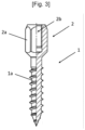
- a pin comprising a self-tapping threaded cylindrical bearing, one end of which has a head arranged for screwing in a threaded rod capable of receiving an element, such as a framework for false ceiling .
- the piton is subjected to a carbonitriding type hardness treatment to be screwed directly into concrete without the use of a dowel.
- the nominal diameter of the self-tapping threaded cylindrical bearing is 6.9 mm, which makes it possible to increase the resistance of the eyebolt, to eliminate the dowel, and therefore, to work more quickly, with less fatigue, and in particular to drill concrete with a standard 6 mm diameter.
- the length of the cylindrical span is 35 mm, to adapt to thin prefabricated concrete slabs.
- the thread pitch of the self-tapping threaded cylindrical seat has also been studied and is preferably 3.2 mm to offer the best grip in concrete.
- the internal thread in the case of a female head, or the threaded cylindrical seat in the case of a male head are present over a length of at least 11 mm.
- the head (2) can be of the female type, as illustrated, being constituted by a hexagonal surface (2a) having an internal tapping (2b) for screwing the threaded rod, preferably present on a length of at least 11 mm.
- the female thread is for example M6 for the false ceiling, M7 for the plumber's collar with M7 base or M8 for the heavy series soundproof collar with M8 base.
- the eyebolt (1) can be screwed directly into the concrete, without the use of a dowel, as recalled in the analysis of the prior art.
- the length of the self-tapping cylindrical seat (1a) is 35.
- the thread pitch of the self-tapping threaded cylindrical seat (1a) is 3.2 mm, and the tip sets an angle of 45° .
- the nominal diameter of the self-tapping threaded cylindrical surface (1a), that is to say including thread is 6.9 mm which allows a drilling of 6 mm in concrete, with a standard drill, while avoiding the use of a dowel, and guaranteeing increased resistance of the eyebolt (1).
Landscapes
- Engineering & Computer Science (AREA)
- General Engineering & Computer Science (AREA)
- Mechanical Engineering (AREA)
- Joining Of Building Structures In Genera (AREA)
- Load-Bearing And Curtain Walls (AREA)
- Finishing Walls (AREA)
Claims (6)
- Aufhänger (1) bestehend aus einem selbstschneidenden, zylindrischen Gewindeschaft (1a), wobei ein Ende einen Kopf (2) aufweist, der zum Einschrauben einer Gewindestange eingerichtet ist, die ein Element wie ein Gerüst für eine abgehängte Decke aufnehmen kann, wobei der Aufhänger (1) einer Härtebehandlung wie der Carbonitrierung unterzogen wird, um direkt in Beton ohne Verwendung eines Dübels eingeschraubt zu werden, dadurch gekennzeichnet, dass der Nenndurchmesser des selbstschneidenden, zylindrischen Gewindeschafts (1a) 6,9 mm beträgt.
- Aufhänger (1) nach Anspruch 1, dadurch gekennzeichnet, dass die Länge des selbstschneidenden, zylindrischen Gewindeschafts (1a) 35 mm beträgt.
- Aufhänger (1) nach Anspruch 1, dadurch gekennzeichnet, dass die Gewindesteigung des selbstschneidenden, zylindrischen Gewindeschafts (1a) 3,2 mm beträgt.
- Aufhänger (1) nach Anspruch 1, dadurch gekennzeichnet, dass er eine Spitze mit einem Winkel von 45° aufweist.
- Aufhänger (1) nach Anspruch 1, dadurch gekennzeichnet, dass der Kopf (2) zum Einschrauben einer Gewindestange vom weiblichen Typ ist, bestehend aus einem sechseckigen Abschnitt (2a) mit einem Innengewinde (2b) zum Einschrauben der genannten Stange.
- Aufhänger (1) nach Anspruch 1, dadurch gekennzeichnet, dass der Kopf (2) zum Einschrauben einer Gewindestange vom männlichen Typ ist, bestehend aus einem zylindrischen Gewindeabschnitt zum Einschrauben der genannten Stange, wobei ein sechseckiger Abschnitt zwischen dem genannten zylindrischen Gewindeabschnitt und dem selbstschneidenden, zylindrischen Gewindeschaft (1a) ausgebildet ist.
Applications Claiming Priority (1)
| Application Number | Priority Date | Filing Date | Title |
|---|---|---|---|
| FR2112725A FR3129694B1 (fr) | 2021-11-30 | 2021-11-30 | Piton de suspension perfectionné |
Publications (3)
| Publication Number | Publication Date |
|---|---|
| EP4187115A1 EP4187115A1 (de) | 2023-05-31 |
| EP4187115B1 true EP4187115B1 (de) | 2024-07-03 |
| EP4187115C0 EP4187115C0 (de) | 2024-07-03 |
Family
ID=79831419
Family Applications (1)
| Application Number | Title | Priority Date | Filing Date |
|---|---|---|---|
| EP22208178.8A Active EP4187115B1 (de) | 2021-11-30 | 2022-11-17 | Verbesserte aufhängevorrichtung |
Country Status (2)
| Country | Link |
|---|---|
| EP (1) | EP4187115B1 (de) |
| FR (1) | FR3129694B1 (de) |
Cited By (1)
| Publication number | Priority date | Publication date | Assignee | Title |
|---|---|---|---|---|
| FR3165293A1 (fr) * | 2024-08-01 | 2026-02-06 | Francois Inglese | Patte à vis perfectionnée |
Family Cites Families (4)
| Publication number | Priority date | Publication date | Assignee | Title |
|---|---|---|---|---|
| US4439077A (en) | 1982-02-11 | 1984-03-27 | Godsted Kent B | Concrete screw anchor |
| CN2545415Y (zh) * | 2002-04-11 | 2003-04-16 | 久可工业股份有限公司 | 具有不同高低螺牙之三线螺纹双头固定螺丝 |
| FR3038354B1 (fr) | 2015-07-03 | 2017-12-29 | Sarl Francois Inglese | Piton de suspension |
| ES2990260T3 (es) * | 2019-06-12 | 2024-11-29 | Illinois Tool Works | Tornillo para hormigón para colgar un armazón de un techo suspendido |
-
2021
- 2021-11-30 FR FR2112725A patent/FR3129694B1/fr active Active
-
2022
- 2022-11-17 EP EP22208178.8A patent/EP4187115B1/de active Active
Cited By (1)
| Publication number | Priority date | Publication date | Assignee | Title |
|---|---|---|---|---|
| FR3165293A1 (fr) * | 2024-08-01 | 2026-02-06 | Francois Inglese | Patte à vis perfectionnée |
Also Published As
| Publication number | Publication date |
|---|---|
| FR3129694B1 (fr) | 2023-12-08 |
| EP4187115A1 (de) | 2023-05-31 |
| FR3129694A1 (fr) | 2023-06-02 |
| EP4187115C0 (de) | 2024-07-03 |
Similar Documents
| Publication | Publication Date | Title |
|---|---|---|
| EP0705987B1 (de) | Selbstschneidende gebohrte Kopfschraube | |
| RU2314441C9 (ru) | Винт с потайной головкой | |
| FR2850435A1 (fr) | Cheville d'ancrage pour materiau friable | |
| FR2739151A1 (fr) | Dispositif de solidarisation d'une piece sur un support | |
| EP4187115B1 (de) | Verbesserte aufhängevorrichtung | |
| CA2346552A1 (fr) | Assemblage filete integral de deux tubes metalliques | |
| FR2784722A1 (fr) | Vis a bois | |
| FR3038354A1 (fr) | Piton de suspension | |
| EP2237730B1 (de) | Osteosynthesevorrichtung mit schnellbefestigungsmitteln | |
| FR2518635A1 (fr) | Joint d'outil comportant des epaulements interieurs/exterieurs d'ajustage | |
| FR2835296A3 (fr) | Vis pour plaque en bois | |
| FR2567432A1 (fr) | Porte-outil, en particulier pour un outil tournant, muni d'un dispositif de reglage axial | |
| US6427289B2 (en) | Tool handle connection system and apparatus, and methods of making and using same | |
| EP0587478A1 (de) | Schneideinsatz für Graviermaschinen | |
| FR3165293A1 (fr) | Patte à vis perfectionnée | |
| EP1467110B1 (de) | Schraube und Befestigungs-Überwurfmutter, insbesondere zur Befestigung von Platten oder Elementen für Abdeckungen bzw. Verkleidungen. | |
| EP0020261B1 (de) | Zange zum konzentrischen Spannen | |
| FR2699617A1 (fr) | Insert à douille et élément fileté. | |
| NZ198528A (en) | Screw/stud extractor;expanding jaw blades engage bore | |
| FR2674160A1 (fr) | Foret pour le percage de materiaux, en particulier de materiaux refractaires. | |
| BE1027500B1 (fr) | Embout et procédé de vissage de crochet de maçonnerie | |
| FR2491804A1 (fr) | Mandrin de serrage pour queue d'outil cylindrique | |
| FR3119178A3 (fr) | Elément de fixation pour robinetterie | |
| FR2689944A1 (fr) | Vis pour tous types de bois naturels et reconstitués et matériaux de synthèse. | |
| GB2293425A (en) | Fixing anchors,e.g.for window or door frames |
Legal Events
| Date | Code | Title | Description |
|---|---|---|---|
| PUAI | Public reference made under article 153(3) epc to a published international application that has entered the european phase |
Free format text: ORIGINAL CODE: 0009012 |
|
| STAA | Information on the status of an ep patent application or granted ep patent |
Free format text: STATUS: THE APPLICATION HAS BEEN PUBLISHED |
|
| AK | Designated contracting states |
Kind code of ref document: A1 Designated state(s): AL AT BE BG CH CY CZ DE DK EE ES FI FR GB GR HR HU IE IS IT LI LT LU LV MC ME MK MT NL NO PL PT RO RS SE SI SK SM TR |
|
| STAA | Information on the status of an ep patent application or granted ep patent |
Free format text: STATUS: REQUEST FOR EXAMINATION WAS MADE |
|
| 17P | Request for examination filed |
Effective date: 20230609 |
|
| RBV | Designated contracting states (corrected) |
Designated state(s): AL AT BE BG CH CY CZ DE DK EE ES FI FR GB GR HR HU IE IS IT LI LT LU LV MC ME MK MT NL NO PL PT RO RS SE SI SK SM TR |
|
| GRAP | Despatch of communication of intention to grant a patent |
Free format text: ORIGINAL CODE: EPIDOSNIGR1 |
|
| STAA | Information on the status of an ep patent application or granted ep patent |
Free format text: STATUS: GRANT OF PATENT IS INTENDED |
|
| INTG | Intention to grant announced |
Effective date: 20240408 |
|
| GRAS | Grant fee paid |
Free format text: ORIGINAL CODE: EPIDOSNIGR3 |
|
| GRAA | (expected) grant |
Free format text: ORIGINAL CODE: 0009210 |
|
| STAA | Information on the status of an ep patent application or granted ep patent |
Free format text: STATUS: THE PATENT HAS BEEN GRANTED |
|
| AK | Designated contracting states |
Kind code of ref document: B1 Designated state(s): AL AT BE BG CH CY CZ DE DK EE ES FI FR GB GR HR HU IE IS IT LI LT LU LV MC ME MK MT NL NO PL PT RO RS SE SI SK SM TR |
|
| REG | Reference to a national code |
Ref country code: CH Ref legal event code: EP |
|
| REG | Reference to a national code |
Ref country code: DE Ref legal event code: R096 Ref document number: 602022004325 Country of ref document: DE |
|
| U01 | Request for unitary effect filed |
Effective date: 20240703 |
|
| U07 | Unitary effect registered |
Designated state(s): AT BE BG DE DK EE FI FR IT LT LU LV MT NL PT SE SI Effective date: 20240709 |
|
| U20 | Renewal fee for the european patent with unitary effect paid |
Year of fee payment: 3 Effective date: 20241126 |
|
| PG25 | Lapsed in a contracting state [announced via postgrant information from national office to epo] |
Ref country code: NO Free format text: LAPSE BECAUSE OF FAILURE TO SUBMIT A TRANSLATION OF THE DESCRIPTION OR TO PAY THE FEE WITHIN THE PRESCRIBED TIME-LIMIT Effective date: 20241003 |
|
| PG25 | Lapsed in a contracting state [announced via postgrant information from national office to epo] |
Ref country code: GR Free format text: LAPSE BECAUSE OF FAILURE TO SUBMIT A TRANSLATION OF THE DESCRIPTION OR TO PAY THE FEE WITHIN THE PRESCRIBED TIME-LIMIT Effective date: 20241004 Ref country code: PL Free format text: LAPSE BECAUSE OF FAILURE TO SUBMIT A TRANSLATION OF THE DESCRIPTION OR TO PAY THE FEE WITHIN THE PRESCRIBED TIME-LIMIT Effective date: 20240703 |
|
| PG25 | Lapsed in a contracting state [announced via postgrant information from national office to epo] |
Ref country code: IS Free format text: LAPSE BECAUSE OF FAILURE TO SUBMIT A TRANSLATION OF THE DESCRIPTION OR TO PAY THE FEE WITHIN THE PRESCRIBED TIME-LIMIT Effective date: 20241103 |
|
| PG25 | Lapsed in a contracting state [announced via postgrant information from national office to epo] |
Ref country code: CZ Free format text: LAPSE BECAUSE OF FAILURE TO SUBMIT A TRANSLATION OF THE DESCRIPTION OR TO PAY THE FEE WITHIN THE PRESCRIBED TIME-LIMIT Effective date: 20240703 Ref country code: HR Free format text: LAPSE BECAUSE OF FAILURE TO SUBMIT A TRANSLATION OF THE DESCRIPTION OR TO PAY THE FEE WITHIN THE PRESCRIBED TIME-LIMIT Effective date: 20240703 |
|
| PG25 | Lapsed in a contracting state [announced via postgrant information from national office to epo] |
Ref country code: ES Free format text: LAPSE BECAUSE OF FAILURE TO SUBMIT A TRANSLATION OF THE DESCRIPTION OR TO PAY THE FEE WITHIN THE PRESCRIBED TIME-LIMIT Effective date: 20240703 Ref country code: RS Free format text: LAPSE BECAUSE OF FAILURE TO SUBMIT A TRANSLATION OF THE DESCRIPTION OR TO PAY THE FEE WITHIN THE PRESCRIBED TIME-LIMIT Effective date: 20241003 |
|
| PG25 | Lapsed in a contracting state [announced via postgrant information from national office to epo] |
Ref country code: RS Free format text: LAPSE BECAUSE OF FAILURE TO SUBMIT A TRANSLATION OF THE DESCRIPTION OR TO PAY THE FEE WITHIN THE PRESCRIBED TIME-LIMIT Effective date: 20241003 Ref country code: PL Free format text: LAPSE BECAUSE OF FAILURE TO SUBMIT A TRANSLATION OF THE DESCRIPTION OR TO PAY THE FEE WITHIN THE PRESCRIBED TIME-LIMIT Effective date: 20240703 Ref country code: NO Free format text: LAPSE BECAUSE OF FAILURE TO SUBMIT A TRANSLATION OF THE DESCRIPTION OR TO PAY THE FEE WITHIN THE PRESCRIBED TIME-LIMIT Effective date: 20241003 Ref country code: IS Free format text: LAPSE BECAUSE OF FAILURE TO SUBMIT A TRANSLATION OF THE DESCRIPTION OR TO PAY THE FEE WITHIN THE PRESCRIBED TIME-LIMIT Effective date: 20241103 Ref country code: HR Free format text: LAPSE BECAUSE OF FAILURE TO SUBMIT A TRANSLATION OF THE DESCRIPTION OR TO PAY THE FEE WITHIN THE PRESCRIBED TIME-LIMIT Effective date: 20240703 Ref country code: GR Free format text: LAPSE BECAUSE OF FAILURE TO SUBMIT A TRANSLATION OF THE DESCRIPTION OR TO PAY THE FEE WITHIN THE PRESCRIBED TIME-LIMIT Effective date: 20241004 Ref country code: ES Free format text: LAPSE BECAUSE OF FAILURE TO SUBMIT A TRANSLATION OF THE DESCRIPTION OR TO PAY THE FEE WITHIN THE PRESCRIBED TIME-LIMIT Effective date: 20240703 Ref country code: CZ Free format text: LAPSE BECAUSE OF FAILURE TO SUBMIT A TRANSLATION OF THE DESCRIPTION OR TO PAY THE FEE WITHIN THE PRESCRIBED TIME-LIMIT Effective date: 20240703 |
|
| PG25 | Lapsed in a contracting state [announced via postgrant information from national office to epo] |
Ref country code: SM Free format text: LAPSE BECAUSE OF FAILURE TO SUBMIT A TRANSLATION OF THE DESCRIPTION OR TO PAY THE FEE WITHIN THE PRESCRIBED TIME-LIMIT Effective date: 20240703 |
|
| PG25 | Lapsed in a contracting state [announced via postgrant information from national office to epo] |
Ref country code: SK Free format text: LAPSE BECAUSE OF FAILURE TO SUBMIT A TRANSLATION OF THE DESCRIPTION OR TO PAY THE FEE WITHIN THE PRESCRIBED TIME-LIMIT Effective date: 20240703 |
|
| PLBE | No opposition filed within time limit |
Free format text: ORIGINAL CODE: 0009261 |
|
| STAA | Information on the status of an ep patent application or granted ep patent |
Free format text: STATUS: NO OPPOSITION FILED WITHIN TIME LIMIT |
|
| 26N | No opposition filed |
Effective date: 20250404 |
|
| PG25 | Lapsed in a contracting state [announced via postgrant information from national office to epo] |
Ref country code: MC Free format text: LAPSE BECAUSE OF FAILURE TO SUBMIT A TRANSLATION OF THE DESCRIPTION OR TO PAY THE FEE WITHIN THE PRESCRIBED TIME-LIMIT Effective date: 20240703 |
|
| PG25 | Lapsed in a contracting state [announced via postgrant information from national office to epo] |
Ref country code: IE Free format text: LAPSE BECAUSE OF NON-PAYMENT OF DUE FEES Effective date: 20241117 |
|
| PG25 | Lapsed in a contracting state [announced via postgrant information from national office to epo] |
Ref country code: RO Free format text: LAPSE BECAUSE OF FAILURE TO SUBMIT A TRANSLATION OF THE DESCRIPTION OR TO PAY THE FEE WITHIN THE PRESCRIBED TIME-LIMIT Effective date: 20240703 |
|
| U20 | Renewal fee for the european patent with unitary effect paid |
Year of fee payment: 4 Effective date: 20251127 |
|
| PG25 | Lapsed in a contracting state [announced via postgrant information from national office to epo] |
Ref country code: HU Free format text: LAPSE BECAUSE OF FAILURE TO SUBMIT A TRANSLATION OF THE DESCRIPTION OR TO PAY THE FEE WITHIN THE PRESCRIBED TIME-LIMIT; INVALID AB INITIO Effective date: 20221117 |
|
| PG25 | Lapsed in a contracting state [announced via postgrant information from national office to epo] |
Ref country code: CY Free format text: LAPSE BECAUSE OF FAILURE TO SUBMIT A TRANSLATION OF THE DESCRIPTION OR TO PAY THE FEE WITHIN THE PRESCRIBED TIME-LIMIT; INVALID AB INITIO Effective date: 20221117 |