EP4186793A2 - Systeme und verfahren zur erkennung von wasserlecks und/oder verhinderung von abwasserüberlauf - Google Patents
Systeme und verfahren zur erkennung von wasserlecks und/oder verhinderung von abwasserüberlauf Download PDFInfo
- Publication number
- EP4186793A2 EP4186793A2 EP22209456.7A EP22209456A EP4186793A2 EP 4186793 A2 EP4186793 A2 EP 4186793A2 EP 22209456 A EP22209456 A EP 22209456A EP 4186793 A2 EP4186793 A2 EP 4186793A2
- Authority
- EP
- European Patent Office
- Prior art keywords
- sensor
- controller
- toilet bowl
- valve
- disposed
- Prior art date
- Legal status (The legal status is an assumption and is not a legal conclusion. Google has not performed a legal analysis and makes no representation as to the accuracy of the status listed.)
- Granted
Links
Images


Classifications
-
- B—PERFORMING OPERATIONS; TRANSPORTING
- B64—AIRCRAFT; AVIATION; COSMONAUTICS
- B64D—EQUIPMENT FOR FITTING IN OR TO AIRCRAFT; FLIGHT SUITS; PARACHUTES; ARRANGEMENT OR MOUNTING OF POWER PLANTS OR PROPULSION TRANSMISSIONS IN AIRCRAFT
- B64D11/00—Passenger or crew accommodation; Flight-deck installations not otherwise provided for
- B64D11/02—Toilet fittings
Definitions
- the present disclosure relates to drain systems and methods for improved overflow detection and, more particularly, improved waste water overflow detection systems and methods for use in aircraft lavatories.
- Aircraft cabins include lavatories having drain systems disposed therein.
- the waste water drain system may result in waste water overflow due to a faulty rinse valve being stuck in an open condition, or the like. In such a condition, waste water may flow continuously into an aircraft lavatory. Additionally, typical waste volume detection in a waste collection tank may be prone to generating erroneous readings. An overflow condition is often detected by passengers in a manual manner.
- a system is disclosed herein.
- the system may comprise: a first sensor disposed in a first toilet bowl; a display device; and a controller electronically coupled to the first sensor, the controller configured to: receive, via the first sensor, a first signal indicating the first sensor is exposed to water, and transmit a second signal to the display device indicating an overflow condition is about to occur in the first toilet bowl.
- the system further comprises a second toilet bowl comprising a second sensor, wherein the first sensor and the second sensor are water sensors.
- the first toilet bowl may be disposed in a first lavatory on an aircraft and the second toilet bowl is disposed in a second lavatory on the aircraft.
- the controller may be configured to determine a location of the first sensor in response to receiving the first signal and transmit the location to the display device to be displayed.
- the system may further comprise a first acoustic emission (AE) sensor and a second AE sensor electronically coupled to the controller, the first AE sensor and the second AE sensor configured to be coupled to a fluid conduit.
- the controller may be configured to receive, via the first AE sensor and the second AE sensor, acoustic data.
- the system may further comprise a second sensor disposed in a waste tank, the waste tank in fluid communication with the first toilet bowl during operation, the second sensor electronically coupled to the controller, the second sensor configured to measure a wastewater level in the waste tank and send to the controller.
- the leak detection sensor may comprise: a fluid conduit; a valve disposed at least partially within the fluid conduit; a first acoustic emission sensor coupled to the fluid conduit upstream of the valve; a second acoustic emission sensor coupled to the fluid conduit downstream of the valve; and a controller in electronic communication with the first acoustic emission sensor and the second acoustic emission sensor, the controller configured to determine a leak at the valve in response to acoustic data received from the first acoustic emission sensor and the second acoustic emission sensor.
- the fluid conduit extends from a toilet bowl to a waste tank.
- the toilet bowl may be disposed in a lavatory of an aircraft.
- the leak detection system may further comprise a display device, the controller in electric communication with the display device, the controller configured to send an indication to the display device in response to determining the leak at the valve.
- the controller may be further configured to send a signal to the valve to close the valve in response to detecting the leak.
- a plumbing system may comprise a first lavatory and a second lavatory having the leak detection system. The controller may be configured to determine whether the first lavatory or the second lavatory has the leak.
- the aircraft may comprise: a toilet bowl disposed in a lavatory; a waste tank; a fluid conduit extending from the toilet bowl to the waste tank; a valve disposed in the fluid conduit, the valve configured to transition from a closed state to an open state to fluidly couple the toilet bowl to the waste tank; a waste water level sensor disposed in the waste tank, the waste water level sensor configured to measure a waste water level within the waste tank; a controller electronically coupled to the waste water level sensor, the controller configured to: receive, via the waste water level sensor, the waste water level in the waste tank, and transmit an indication to a display device in response to the waste water level exceeding a threshold level.
- the aircraft may further comprise a second sensor disposed in the toilet bowl, the second sensor comprising a water sensor.
- the second sensor may be disposed inside the toilet bowl at a height above an estimated maximum waste water threshold during operation of the toilet bowl.
- the waste water level sensor may comprises a fluorinated ethylene propylene (FEP) coating.
- FEP fluorinated ethylene propylene
- the aircraft may further comprise a first acoustic emission sensor disposed upstream of the valve, the first acoustic emission sensor in electronic communication with the controller, the controller configured to determine a leak in the fluid conduit.
- the aircraft may further comprise a second acoustic emission sensor disposed downstream of the valve, the second acoustic emission sensor in electronic communication with the controller, the controller configured to determine the leak in the fluid conduit based on measurements form the first acoustic emission sensor and the second acoustic emission sensor.
- Overflow of a toilet bowl may lead to discomfort, inconvenience to passengers, blockage of lavatory use, etc.
- Leakage due to a malfunctioning rinse valve may cause a toilet drainage system to continuously run and lead to an emptying of clean water and filling of a waste tank.
- erroneous readings of waste level in a waste tank may lead to blocking a lavatory use unnecessarily, resulting in discomfort of passengers due to long wait lines or the like.
- Overflow conditions of typical plumbing systems are manually detected (e.g., via a passenger or service person upon an aircraft).
- the waste water leakage detection system may comprise a first acoustic emission (AE) sensor, a second AE sensor, a rinse valve, and a fluid conduit.
- the valve is disposed within the fluid conduit.
- the first AE sensor is disposed upstream of the valve and the second AE sensor is disposed downstream of the valve.
- measurements from the first AE sensor and the second AE sensor may be compared and/or analyzed (e.g., by a processor), to determine whether fluid is leaking past the valve, in accordance with various embodiments.
- the waste water leakage detection system may facilitate real-time and/or accurate leakage data (e.g., via pattern recognition or the like).
- the system in response to the waste water leakage detection system determining a leak (e.g., due to a faulty valve), the system may be configured to identify the leakage location (e.g., which lavatory or fixture in a lavatory), a mass flow rate of leakage, and/or send an indication signal to a crew member, in accordance with various embodiments.
- the rinse valve and manual inlet valve may be closed prior to or shortly after an overflow condition occurring.
- the overflow detection system may comprise a first sensor disposed in a toilet bowl and a second sensor disposed in a waste water tank.
- the first sensor may be configured to detect when a water level has been exceeded within the toilet bowl.
- the first sensor may comprise a water sensor.
- the water sensor may be configured to detect when the sensor is exposed to water.
- the water sensor may be disposed at a predetermined height in the toilet bowl and send a signal to the overflow detections system in response to being exposed to water.
- the second sensor may be configured to detect a waste level in the waste water tank.
- the second sensor may comprise a coating disposed thereon.
- the coating may comprise fluorinated ethylene propylene (FEP).
- FEP fluorinated ethylene propylene
- the coating may be configured to prevent adhesion to the second sensor.
- the second sensor may be configured to prevent adhesion and/or accumulation of waste water on the second sensor, thus preventing false readings and resulting in greater accuracy, in accordance with various embodiments.
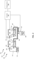
- the lavatory 100 comprises a toilet 110, a water basin 120 (e.g., a sink), and a faucet 130.
- the lavatory 100 further comprises a plumbing system 200.
- the plumbing system 200 is in fluid communication with the toilet 110, the water basin 120, and the faucet 130.
- waste water may be transferred throughout the plumbing system 200 as described further herein.
- running water via the faucet 130 waste water may be transferred throughout the plumbing system 200 as described further herein.
- the plumbing system 200 comprises a rinse valve 205 associated with each toilet bowl (e.g., toilet bowls 203, 204).
- the rinse valve 205 is configured to open in response to external activation (e.g., via flushing of a handle, via a sensor detecting a person is no longer in front of the sensor, or the like).
- waste water e.g., potable water
- fluid conduits 209 may flow from a potable water tank 214 to a toilet bowl 203 or toilet bowl 204.
- waste water may be dispensed through a fluid conduits 206, 207 from each toilet bowl (e.g., toilet bowls 203, 204) to the waste tank 208.
- any solid waste may be transported from the toilet bowl (e.g., toilet bowl 203 or toilet bowl 204) to the waste tank 208 as waste water, in accordance with various embodiments.
- the overflow detection system 201 comprises a first sensor 210 configured to be disposed in each toilet bowl (e.g., first toilet bowl 203 and second toilet bowl 204) of the plumbing system 200.
- a plurality of the first sensor 210 may be disposed around (e.g., partially or fully) a circumference of a respective toilet bowl (e.g., toilet bowls 203, 204). The present disclosure is not limited in this regard.
- the first sensor 210 is in electronic (i.e., electrical or wireless) communication with a controller 250.
- controller 250 may be integrated into computer system of the aircraft.
- controller 250 may be configured as a central network element or hub to access various systems and components of the overflow detection system 201 and/or the leak detection system 202.
- Controller 250 may comprise a network, computer-based system, and/or software components configured to provide an access point to various systems and components of the overflow detection system 201 and/or the leak detection system 202.
- controller 250 may comprise a processor.
- controller 250 may be implemented in a single processor.
- controller 250 may be implemented as and may include one or more processors and/or one or more tangible, non-transitory memories and be capable of implementing logic.
- processors can be a general purpose processor, a digital signal processor (DSP), an application specific integrated circuit (ASIC), a field programable gate array (FPGA) or other programable logic device, discrete gate or transistor logic, discrete hardware components, or any combination thereof.
- Controller 250 may comprise a processor configured to implement various logical operations in response to execution of instructions, for example, instructions stored on a non-transitory, tangible, computer-readable medium configured to communicate with controller 250.
- System program instructions and/or controller instructions may be loaded onto a non-transitory, tangible computer-readable medium having instructions stored thereon that, in response to execution by a controller, cause the controller to perform various operations.
- the term "non-transitory” is to be understood to remove only propagating transitory signals per se from the claim scope and does not relinquish rights to all standard computer-readable media that are not only propagating transitory signals per se. Stated another way, the meaning of the term “non-transitory computer-readable medium” and “non-transitory computer-readable storage medium” should be construed to exclude only those types of transitory computer-readable media which were found in In Re Nuijten to fall outside the scope of patentable subject matter under 35 U.S.C. ⁇ 101.
- the first sensor is spaced apart vertically from an estimated maximum water level 211 during use of each toilet bowl (e.g., toilet bowls 203, 204). In this regard, the first sensor 210 may be prevented from activation during normal operation of the plumbing system 200.
- the first sensor 210 is a water sensor (i.e., configured to detect water). The first sensor 210 is configured to send a signal the controller 250 in response to detecting water. In this regard, in response to water in the toilet bowl (e.g., toilet bowl 203 or toilet bowl 204) reaching a level of the first sensor 210, the first sensor 210 sends an indication to the controller 250.
- the controller may be configured to determine from the signal sent by the first sensor 210 a location of the sensor (e.g., in a forward lavatory, aft lavatory, or the like) and send an indication to a display device (or indicator) that an overflow condition has occurred.
- a crew member may be notified (e.g., via the display device) that a toilet bowl (e.g., toilet bowl 203 or toilet bowl 204) is experiencing an overflow condition (i.e., water has extended vertically past the first sensor 210), and in which lavatory the overflow is occurring.
- the controller 250 may determine, based on which sensor 210 the signal is received from, which lavatory has a toilet bowl (e.g., toilet bowl 203 or toilet bowl 204) that is about to experience an overflow condition. Thus, in response to a crew member seeing the indication, the crew member may manually close an inlet shutoff valve 213.
- the inlet shutoff valve 213 is disposed fluidly between the potable water tank 214 and the rinse valve 205. In this regard, the inlet shutoff valve prevents potable water from flowing into the toilet bowl 203 in response to being in a closed position.
- the controller 250 may be in electronic communication with the valve 205.
- the controller 250 may be configured to command the valve 205 to close in response to receiving a signal from the first sensor 210 via a secondary closing mechanism (e.g., a closing mechanism independent of a primary closing mechanism for the valve 205).
- the second sensor 220 is disposed within the waste tank 208.
- the second sensor 220 may also be in electronic communication with the controller 250.
- the second sensor 220 comprises a waste water level sensor.
- the waste water level sensor may extend from a top portion of the waste tank 208 towards a bottom portion of the waste tank 208.
- the waste tank 208 may continuously provide a waste water level in the waste tank 208 to the controller 250.
- a predetermined threshold e.g., 100 % vertical height of the waste water level sensor
- the controller 250 may send a signal to the display device 260.
- the controller 250 may be configured to send a warning signal at a predetermined level (e.g., 80% vertical height of the waste water level sensor) to indicate the waste tank should be emptied soon.
- the waste water level sensor may comprise an FEP coating disposed therein.
- the FEP coating may provide excellent abrasion resistance due, at least in part, to being non-porous, chemical resistant, having a low coefficient of friction, etc., in accordance with various embodiments.
- the FEP coating may be between 0.5 mm (0.2 in) and 5 mm (2.0 in) thick, or between 1 mm (0.4 in) and 2 mm (0.8 in) thick, or approximately 1.5 mm (0.6 in) thick.
- the FEP coating may prevent erroneous readings experienced by typical point level sensors, in accordance with various embodiments.
- the FEP coating may provide a non-stick measurement probe without holes, moving parts, hidden voids, or the like.
- the waste level sensor may be a conductive sensor, facilitating use within waste tank 208 regardless of material type and regardless of any film that may build up on the walls of the waste tank 208.
- the second sensor 220 may be configured to provide a true volumetric output reading regardless of a shape of waste tank 208 (e.g., irregular shapes). In this regard, greater accuracy of waste water level within the waste tank 208 may be delineated.
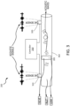
- the leak detection system 202 of the plumbing system 200 from FIG. 3 is illustrated, in accordance with various embodiments.
- the leak detection system 202 comprises a first AE sensor 310 and a second AE sensor 320.
- the first AE sensor 310 and the second AE sensor 320 may be disposed on a radially outer surface of a fluid conduit 302 in the plumbing system 200 from FIG. 2 .
- the fluid conduit 302 may be in accordance with fluid conduit 206 or fluid conduit 207 or the like.
- the valve 205 of the plumbing system 200 from FIG. 2 is disposed axially between the first AE sensor 310 and the second AE sensor 320.
- the first AE sensor 310 is disposed upstream of the valve 205 and the second AE sensor 320 is disposed downstream of the valve 205.
- the AE sensors 310, 320 are configured to detect, track, and measure AE signals as they propagate through the fluid conduit 302. For example, escaping fluid (e.g., at the valve 205) creates an acoustic signal as it passes through a perforation in the fluid conduit 302 or the valve 205.
- the controller 250 may be trained to detect a leak via a leak classifier trained with a neural network (e.g., a deep neural network (DNN), an artificial neural network (ANN), or the like).
- a neural network e.g., a deep neural network (DNN), an artificial neural network (ANN), or the like.
- any or all of the following variables of the detected acoustic signals may be utilized for leak detection by the controller 250: peak, mean, and/or standard deviation in a time domain and/or skewness, kurtosis, or peak frequency in a frequency domain.
- the neural network may determine which variable(s) is/are best suited for determining a leak.
- other variables may be utilized alone or in combination with the variables previously mentioned, namely energy, root-mean squared, crest factor, and/or frequency centroid. The present disclosure is not limited in this regard.
- a selection algorithm based on cross entropy may be employed to rank the variables from best to worst for leak detection.
- a set of variables may be determined based on the selection algorithm.
- leak rates and propagating distances may be factored in to consider the behavior of the variables that are most accurate relative to other variables.
- variable(s) may be determined for use in the leak detection system 202.
- the controller 250 may determine, based on measurements from the AE sensors 310, 320, whether there is a leak proximate the valve 205. Based on a variable set determined from the neural network a leak detection accuracy between 95% and 100% may be obtained. For example, a variable set including peak, mean, frequency, and kurtosis may provide between 95% and 100% leak detection accuracy, in accordance with various embodiments.
- an indication signal may be sent to display device 260 from FIG. 2 .
- a crew member may be informed that a respective valve is leaking and close the valve manually, in accordance with various embodiments.
- the leak detection system 202 and the overflow detection system 201 may be utilized independently or in combination.
- the present disclosure is not limited in this regard.
- the leak detection system 202 may be utilized without the overflow detection system 201 and vice versa.
- the first sensor 210 may be utilized without the second sensor 220 and vice versa.
- systems 201, 202 may detect leaking and/or near overflow of a toilet bowl (e.g., toilet bowl 203 or toilet bowl 204) via the valve 205 in advance to prevent the overflow condition.
- the systems 201, 202 signals to a crew member that an overflow condition is occurring or about to occur, as opposed to awaiting visual detection by a person, increasing safety and comfortability for passengers.
- the systems 201, 202 may provide real time monitoring of leakage of the valve 205 and potential overflow of waste water in a lavatory to crew members.
- the systems 201, 202 are more accurate and reliable relative to manual detection systems and methods.
- the control system 400 may comprise AE sensors 310, 320, water sensor 210, level sensor 220 and the display device 260.
- the controller 250 receives acoustic data from the AE sensors 310, 320, water exposure data from water sensor 210, and/or waste level data from the level sensor 220.
- the controller may determine whether an leak and/or overflow condition is occurring based on the combination of data (e.g., acoustic data and water sensor data), in accordance with various embodiments.
- a more robust and/or accurate leak / overflow detection system may be created, in accordance with various embodiments.
- the controller 250 is in electronic communication with the inlet shutoff valve 213. In this regard, in response to determining a leak or an overflow condition is occurring, or about to occur, the controller 250 may command the inlet shutoff valve to transition from an open position to a closed position to prevent a flow from the potable water tank 214 into a respective toilet bowl 203, in accordance with various embodiments.
- references to "one embodiment”, “an embodiment”, “an example embodiment”, etc. indicate that the embodiment described may include a particular feature, structure, or characteristic, but every embodiment may not necessarily include the particular feature, structure, or characteristic. Moreover, such phrases are not necessarily referring to the same embodiment. Further, when a particular feature, structure, or characteristic is described in connection with an embodiment, it is submitted that it is within the knowledge of one skilled in the art to affect such feature, structure, or characteristic in connection with other embodiments whether or not explicitly described. After reading the description, it will be apparent to one skilled in the relevant art(s) how to implement the disclosure in alternative embodiments.
Landscapes
- Engineering & Computer Science (AREA)
- Aviation & Aerospace Engineering (AREA)
- Sanitary Device For Flush Toilet (AREA)
- Examining Or Testing Airtightness (AREA)
Applications Claiming Priority (2)
| Application Number | Priority Date | Filing Date | Title |
|---|---|---|---|
| IN202141054170 | 2021-11-24 | ||
| US17/848,868 US12146814B2 (en) | 2021-11-24 | 2022-06-24 | Systems and methods for detecting water leaks and/or preventing waste water overflow |
Publications (3)
| Publication Number | Publication Date |
|---|---|
| EP4186793A2 true EP4186793A2 (de) | 2023-05-31 |
| EP4186793A3 EP4186793A3 (de) | 2023-08-30 |
| EP4186793B1 EP4186793B1 (de) | 2025-10-15 |
Family
ID=84361505
Family Applications (1)
| Application Number | Title | Priority Date | Filing Date |
|---|---|---|---|
| EP22209456.7A Active EP4186793B1 (de) | 2021-11-24 | 2022-11-24 | Systeme und verfahren zur erkennung von wasserlecks und verhinderung von abwasserüberlauf |
Country Status (1)
| Country | Link |
|---|---|
| EP (1) | EP4186793B1 (de) |
Cited By (1)
| Publication number | Priority date | Publication date | Assignee | Title |
|---|---|---|---|---|
| CN119617319A (zh) * | 2024-12-09 | 2025-03-14 | 中国商用飞机有限责任公司 | 一种泄漏检测系统、方法及飞行器 |
Family Cites Families (9)
| Publication number | Priority date | Publication date | Assignee | Title |
|---|---|---|---|---|
| US5732417A (en) * | 1996-03-12 | 1998-03-31 | Envirovac Inc. | Vaccum toilet system |
| US6178569B1 (en) * | 1999-04-19 | 2001-01-30 | Niccole Family Trust | Toilet overflow control |
| WO2006042053A2 (en) * | 2004-10-07 | 2006-04-20 | Richard Quintana | Intelligent flow control unit and water management system |
| US20060174707A1 (en) * | 2005-02-09 | 2006-08-10 | Zhang Jack K | Intelligent valve control methods and systems |
| DE202009010176U1 (de) * | 2009-07-27 | 2009-12-03 | Evac Gmbh | Vakuumtoilette und Steuereinheit zum Steuern eines Betriebs einer Vakuumtoilette |
| DE102011018809A1 (de) * | 2011-04-27 | 2012-10-31 | Airbus Operations Gmbh | Vakuumtoiletteneinheit mit Urinalfunktion |
| US9568390B2 (en) * | 2013-06-27 | 2017-02-14 | Dresser, Inc. | System and method for filtering noise from acoustic energy from a valve |
| US20160289945A1 (en) * | 2016-03-17 | 2016-10-06 | Robert W. Seneff | Combination toilet and urinal |
| CN112483908A (zh) * | 2020-11-23 | 2021-03-12 | 中国华能集团清洁能源技术研究院有限公司 | 一种基于声波的管道监测系统及监测方法 |
-
2022
- 2022-11-24 EP EP22209456.7A patent/EP4186793B1/de active Active
Cited By (1)
| Publication number | Priority date | Publication date | Assignee | Title |
|---|---|---|---|---|
| CN119617319A (zh) * | 2024-12-09 | 2025-03-14 | 中国商用飞机有限责任公司 | 一种泄漏检测系统、方法及飞行器 |
Also Published As
| Publication number | Publication date |
|---|---|
| EP4186793B1 (de) | 2025-10-15 |
| EP4186793A3 (de) | 2023-08-30 |
Similar Documents
| Publication | Publication Date | Title |
|---|---|---|
| US12146814B2 (en) | Systems and methods for detecting water leaks and/or preventing waste water overflow | |
| US10107665B2 (en) | Toilet with flush jet fill tube flow meter | |
| JP5605765B2 (ja) | トイレ装置 | |
| US20160161940A1 (en) | Intelligent water emergency system | |
| CN109415892A (zh) | 自动将释放到马桶便池的水量调节成与便池内容物一致的系统、包括这种系统的马桶以及相关方法 | |
| JP2013090748A (ja) | 排尿情報測定装置 | |
| US10877493B2 (en) | Monitoring system for monitoring a water level in a plumbing element, and a plumbing element | |
| WO2017219142A1 (en) | Fluid flow measuring and control devices and method | |
| US20150105694A1 (en) | Urine Flow Meter And A Method To Measure Urination Flow | |
| US20140020167A1 (en) | Combination of vacuum toilet and grey water system functions | |
| US20190003171A1 (en) | Method for Controlling a Vacuum Sewage System for a Building or for a Marine Vessel | |
| EP4186793B1 (de) | Systeme und verfahren zur erkennung von wasserlecks und verhinderung von abwasserüberlauf | |
| JP5821472B2 (ja) | トイレ装置 | |
| US11959791B2 (en) | Systems and methods for smart point level sensing of waste tank | |
| KR102719702B1 (ko) | 급배수설비의 이상감지시스템 | |
| JP6459139B2 (ja) | 検知装置及び小便器洗浄装置 | |
| EP4194820B1 (de) | Systeme und verfahren zur intelligenten punktebenenmessung eines flugzeugabfalltanks | |
| JP6471891B2 (ja) | 排泄情報測定装置 | |
| EP4137646A1 (de) | Ultraschallsensorbasierte ablaufsysteme und verfahren | |
| US12018972B2 (en) | Contactless waste tank level sensing systems and methods | |
| JP6927372B2 (ja) | 貯湯式電気温水器 | |
| EP4187212A1 (de) | Kontaktlose systeme und verfahren zur messung des abfalltankfüllstands | |
| EP4155472A1 (de) | System und verfahren zur verwaltung, steuerung und prädiktiven wartung in anlagen in feuchträumen und flüssigkeitsverteilungsnetzen | |
| US20230056884A1 (en) | Ultrasonic sensor based drain systems and methods | |
| EP3705895B1 (de) | Urinalsensorsystem |
Legal Events
| Date | Code | Title | Description |
|---|---|---|---|
| PUAI | Public reference made under article 153(3) epc to a published international application that has entered the european phase |
Free format text: ORIGINAL CODE: 0009012 |
|
| STAA | Information on the status of an ep patent application or granted ep patent |
Free format text: STATUS: THE APPLICATION HAS BEEN PUBLISHED |
|
| AK | Designated contracting states |
Kind code of ref document: A2 Designated state(s): AL AT BE BG CH CY CZ DE DK EE ES FI FR GB GR HR HU IE IS IT LI LT LU LV MC ME MK MT NL NO PL PT RO RS SE SI SK SM TR |
|
| PUAL | Search report despatched |
Free format text: ORIGINAL CODE: 0009013 |
|
| AK | Designated contracting states |
Kind code of ref document: A3 Designated state(s): AL AT BE BG CH CY CZ DE DK EE ES FI FR GB GR HR HU IE IS IT LI LT LU LV MC ME MK MT NL NO PL PT RO RS SE SI SK SM TR |
|
| RIC1 | Information provided on ipc code assigned before grant |
Ipc: F17D 5/06 20060101ALI20230725BHEP Ipc: B64D 11/02 20060101AFI20230725BHEP |
|
| P01 | Opt-out of the competence of the unified patent court (upc) registered |
Effective date: 20230922 |
|
| STAA | Information on the status of an ep patent application or granted ep patent |
Free format text: STATUS: REQUEST FOR EXAMINATION WAS MADE |
|
| 17P | Request for examination filed |
Effective date: 20240229 |
|
| RBV | Designated contracting states (corrected) |
Designated state(s): AL AT BE BG CH CY CZ DE DK EE ES FI FR GB GR HR HU IE IS IT LI LT LU LV MC ME MK MT NL NO PL PT RO RS SE SI SK SM TR |
|
| GRAP | Despatch of communication of intention to grant a patent |
Free format text: ORIGINAL CODE: EPIDOSNIGR1 |
|
| STAA | Information on the status of an ep patent application or granted ep patent |
Free format text: STATUS: GRANT OF PATENT IS INTENDED |
|
| INTG | Intention to grant announced |
Effective date: 20250512 |
|
| GRAS | Grant fee paid |
Free format text: ORIGINAL CODE: EPIDOSNIGR3 |
|
| GRAA | (expected) grant |
Free format text: ORIGINAL CODE: 0009210 |
|
| STAA | Information on the status of an ep patent application or granted ep patent |
Free format text: STATUS: THE PATENT HAS BEEN GRANTED |
|
| AK | Designated contracting states |
Kind code of ref document: B1 Designated state(s): AL AT BE BG CH CY CZ DE DK EE ES FI FR GB GR HR HU IE IS IT LI LT LU LV MC ME MK MT NL NO PL PT RO RS SE SI SK SM TR |
|
| REG | Reference to a national code |
Ref country code: GB Ref legal event code: FG4D Ref country code: CH Ref legal event code: F10 Free format text: ST27 STATUS EVENT CODE: U-0-0-F10-F00 (AS PROVIDED BY THE NATIONAL OFFICE) Effective date: 20251015 |
|
| REG | Reference to a national code |
Ref country code: IE Ref legal event code: FG4D |
|
| REG | Reference to a national code |
Ref country code: DE Ref legal event code: R096 Ref document number: 602022022992 Country of ref document: DE |
|
| PGFP | Annual fee paid to national office [announced via postgrant information from national office to epo] |
Ref country code: DE Payment date: 20251022 Year of fee payment: 4 |
|
| PGFP | Annual fee paid to national office [announced via postgrant information from national office to epo] |
Ref country code: AT Payment date: 20260113 Year of fee payment: 4 |
|
| PGFP | Annual fee paid to national office [announced via postgrant information from national office to epo] |
Ref country code: FR Payment date: 20251119 Year of fee payment: 4 |
|
| REG | Reference to a national code |
Ref country code: NL Ref legal event code: MP Effective date: 20251015 |
|
| REG | Reference to a national code |
Ref country code: AT Ref legal event code: MK05 Ref document number: 1846769 Country of ref document: AT Kind code of ref document: T Effective date: 20251015 |
|
| PG25 | Lapsed in a contracting state [announced via postgrant information from national office to epo] |
Ref country code: NL Free format text: LAPSE BECAUSE OF FAILURE TO SUBMIT A TRANSLATION OF THE DESCRIPTION OR TO PAY THE FEE WITHIN THE PRESCRIBED TIME-LIMIT Effective date: 20251015 |
|
| PG25 | Lapsed in a contracting state [announced via postgrant information from national office to epo] |
Ref country code: ES Free format text: LAPSE BECAUSE OF FAILURE TO SUBMIT A TRANSLATION OF THE DESCRIPTION OR TO PAY THE FEE WITHIN THE PRESCRIBED TIME-LIMIT Effective date: 20251015 |
|
| REG | Reference to a national code |
Ref country code: LT Ref legal event code: MG9D |
|
| PG25 | Lapsed in a contracting state [announced via postgrant information from national office to epo] |
Ref country code: NO Free format text: LAPSE BECAUSE OF FAILURE TO SUBMIT A TRANSLATION OF THE DESCRIPTION OR TO PAY THE FEE WITHIN THE PRESCRIBED TIME-LIMIT Effective date: 20260115 |
|
| PG25 | Lapsed in a contracting state [announced via postgrant information from national office to epo] |
Ref country code: HR Free format text: LAPSE BECAUSE OF FAILURE TO SUBMIT A TRANSLATION OF THE DESCRIPTION OR TO PAY THE FEE WITHIN THE PRESCRIBED TIME-LIMIT Effective date: 20251015 Ref country code: AT Free format text: LAPSE BECAUSE OF FAILURE TO SUBMIT A TRANSLATION OF THE DESCRIPTION OR TO PAY THE FEE WITHIN THE PRESCRIBED TIME-LIMIT Effective date: 20251015 Ref country code: FI Free format text: LAPSE BECAUSE OF FAILURE TO SUBMIT A TRANSLATION OF THE DESCRIPTION OR TO PAY THE FEE WITHIN THE PRESCRIBED TIME-LIMIT Effective date: 20251015 |
|
| PG25 | Lapsed in a contracting state [announced via postgrant information from national office to epo] |
Ref country code: RS Free format text: LAPSE BECAUSE OF FAILURE TO SUBMIT A TRANSLATION OF THE DESCRIPTION OR TO PAY THE FEE WITHIN THE PRESCRIBED TIME-LIMIT Effective date: 20260115 |
|
| PG25 | Lapsed in a contracting state [announced via postgrant information from national office to epo] |
Ref country code: IS Free format text: LAPSE BECAUSE OF FAILURE TO SUBMIT A TRANSLATION OF THE DESCRIPTION OR TO PAY THE FEE WITHIN THE PRESCRIBED TIME-LIMIT Effective date: 20260215 |
|
| PG25 | Lapsed in a contracting state [announced via postgrant information from national office to epo] |
Ref country code: PT Free format text: LAPSE BECAUSE OF FAILURE TO SUBMIT A TRANSLATION OF THE DESCRIPTION OR TO PAY THE FEE WITHIN THE PRESCRIBED TIME-LIMIT Effective date: 20260216 |
|
| PG25 | Lapsed in a contracting state [announced via postgrant information from national office to epo] |
Ref country code: PL Free format text: LAPSE BECAUSE OF FAILURE TO SUBMIT A TRANSLATION OF THE DESCRIPTION OR TO PAY THE FEE WITHIN THE PRESCRIBED TIME-LIMIT Effective date: 20251015 |
|
| PG25 | Lapsed in a contracting state [announced via postgrant information from national office to epo] |
Ref country code: LV Free format text: LAPSE BECAUSE OF FAILURE TO SUBMIT A TRANSLATION OF THE DESCRIPTION OR TO PAY THE FEE WITHIN THE PRESCRIBED TIME-LIMIT Effective date: 20251015 |
|
| PG25 | Lapsed in a contracting state [announced via postgrant information from national office to epo] |
Ref country code: BG Free format text: LAPSE BECAUSE OF FAILURE TO SUBMIT A TRANSLATION OF THE DESCRIPTION OR TO PAY THE FEE WITHIN THE PRESCRIBED TIME-LIMIT Effective date: 20251015 |