EP4186732A1 - Vehicle-mounted dc/dc bond strap detection circuit - Google Patents
Vehicle-mounted dc/dc bond strap detection circuit Download PDFInfo
- Publication number
- EP4186732A1 EP4186732A1 EP20943999.1A EP20943999A EP4186732A1 EP 4186732 A1 EP4186732 A1 EP 4186732A1 EP 20943999 A EP20943999 A EP 20943999A EP 4186732 A1 EP4186732 A1 EP 4186732A1
- Authority
- EP
- European Patent Office
- Prior art keywords
- board
- converter
- resistor
- detection circuit
- ground wire
- Prior art date
- Legal status (The legal status is an assumption and is not a legal conclusion. Google has not performed a legal analysis and makes no representation as to the accuracy of the status listed.)
- Pending
Links
- 238000001514 detection method Methods 0.000 title claims abstract description 78
- 238000000034 method Methods 0.000 claims abstract description 7
- 239000003990 capacitor Substances 0.000 claims description 24
- 238000010586 diagram Methods 0.000 description 9
- 230000002159 abnormal effect Effects 0.000 description 4
- 238000004891 communication Methods 0.000 description 3
- 230000008878 coupling Effects 0.000 description 3
- 238000010168 coupling process Methods 0.000 description 3
- 238000005859 coupling reaction Methods 0.000 description 3
- 230000000694 effects Effects 0.000 description 2
- RYGMFSIKBFXOCR-UHFFFAOYSA-N Copper Chemical compound [Cu] RYGMFSIKBFXOCR-UHFFFAOYSA-N 0.000 description 1
- WHXSMMKQMYFTQS-UHFFFAOYSA-N Lithium Chemical compound [Li] WHXSMMKQMYFTQS-UHFFFAOYSA-N 0.000 description 1
- 230000000712 assembly Effects 0.000 description 1
- 238000000429 assembly Methods 0.000 description 1
- 230000009286 beneficial effect Effects 0.000 description 1
- 238000002485 combustion reaction Methods 0.000 description 1
- 229910052802 copper Inorganic materials 0.000 description 1
- 239000010949 copper Substances 0.000 description 1
- 238000005516 engineering process Methods 0.000 description 1
- 230000007613 environmental effect Effects 0.000 description 1
- 238000010438 heat treatment Methods 0.000 description 1
- 229910052744 lithium Inorganic materials 0.000 description 1
Images


Classifications
-
- G—PHYSICS
- G01—MEASURING; TESTING
- G01R—MEASURING ELECTRIC VARIABLES; MEASURING MAGNETIC VARIABLES
- G01R31/00—Arrangements for testing electric properties; Arrangements for locating electric faults; Arrangements for electrical testing characterised by what is being tested not provided for elsewhere
- G01R31/50—Testing of electric apparatus, lines, cables or components for short-circuits, continuity, leakage current or incorrect line connections
- G01R31/66—Testing of connections, e.g. of plugs or non-disconnectable joints
-
- B—PERFORMING OPERATIONS; TRANSPORTING
- B60—VEHICLES IN GENERAL
- B60L—PROPULSION OF ELECTRICALLY-PROPELLED VEHICLES; SUPPLYING ELECTRIC POWER FOR AUXILIARY EQUIPMENT OF ELECTRICALLY-PROPELLED VEHICLES; ELECTRODYNAMIC BRAKE SYSTEMS FOR VEHICLES IN GENERAL; MAGNETIC SUSPENSION OR LEVITATION FOR VEHICLES; MONITORING OPERATING VARIABLES OF ELECTRICALLY-PROPELLED VEHICLES; ELECTRIC SAFETY DEVICES FOR ELECTRICALLY-PROPELLED VEHICLES
- B60L53/00—Methods of charging batteries, specially adapted for electric vehicles; Charging stations or on-board charging equipment therefor; Exchange of energy storage elements in electric vehicles
- B60L53/20—Methods of charging batteries, specially adapted for electric vehicles; Charging stations or on-board charging equipment therefor; Exchange of energy storage elements in electric vehicles characterised by converters located in the vehicle
- B60L53/22—Constructional details or arrangements of charging converters specially adapted for charging electric vehicles
-
- B—PERFORMING OPERATIONS; TRANSPORTING
- B60—VEHICLES IN GENERAL
- B60L—PROPULSION OF ELECTRICALLY-PROPELLED VEHICLES; SUPPLYING ELECTRIC POWER FOR AUXILIARY EQUIPMENT OF ELECTRICALLY-PROPELLED VEHICLES; ELECTRODYNAMIC BRAKE SYSTEMS FOR VEHICLES IN GENERAL; MAGNETIC SUSPENSION OR LEVITATION FOR VEHICLES; MONITORING OPERATING VARIABLES OF ELECTRICALLY-PROPELLED VEHICLES; ELECTRIC SAFETY DEVICES FOR ELECTRICALLY-PROPELLED VEHICLES
- B60L9/00—Electric propulsion with power supply external to the vehicle
- B60L9/02—Electric propulsion with power supply external to the vehicle using DC motors
- B60L9/08—Electric propulsion with power supply external to the vehicle using DC motors fed from AC supply lines
- B60L9/12—Electric propulsion with power supply external to the vehicle using DC motors fed from AC supply lines with static converters
-
- G—PHYSICS
- G01—MEASURING; TESTING
- G01R—MEASURING ELECTRIC VARIABLES; MEASURING MAGNETIC VARIABLES
- G01R19/00—Arrangements for measuring currents or voltages or for indicating presence or sign thereof
- G01R19/0038—Circuits for comparing several input signals and for indicating the result of this comparison, e.g. equal, different, greater, smaller (comparing pulses or pulse trains according to amplitude)
-
- G—PHYSICS
- G01—MEASURING; TESTING
- G01R—MEASURING ELECTRIC VARIABLES; MEASURING MAGNETIC VARIABLES
- G01R31/00—Arrangements for testing electric properties; Arrangements for locating electric faults; Arrangements for electrical testing characterised by what is being tested not provided for elsewhere
- G01R31/005—Testing of electric installations on transport means
- G01R31/006—Testing of electric installations on transport means on road vehicles, e.g. automobiles or trucks
-
- G—PHYSICS
- G01—MEASURING; TESTING
- G01R—MEASURING ELECTRIC VARIABLES; MEASURING MAGNETIC VARIABLES
- G01R31/00—Arrangements for testing electric properties; Arrangements for locating electric faults; Arrangements for electrical testing characterised by what is being tested not provided for elsewhere
- G01R31/50—Testing of electric apparatus, lines, cables or components for short-circuits, continuity, leakage current or incorrect line connections
- G01R31/52—Testing for short-circuits, leakage current or ground faults
-
- H—ELECTRICITY
- H02—GENERATION; CONVERSION OR DISTRIBUTION OF ELECTRIC POWER
- H02M—APPARATUS FOR CONVERSION BETWEEN AC AND AC, BETWEEN AC AND DC, OR BETWEEN DC AND DC, AND FOR USE WITH MAINS OR SIMILAR POWER SUPPLY SYSTEMS; CONVERSION OF DC OR AC INPUT POWER INTO SURGE OUTPUT POWER; CONTROL OR REGULATION THEREOF
- H02M3/00—Conversion of DC power input into DC power output
Definitions
- This disclosure relates to the field of electronic circuits technology, and in particular to a detection circuit for an on-board direct current/direct current (DC/DC) ground wire.
- DC/DC direct current/direct current
- new energy vehicles have been increasingly recognized due to requirements of environmental protection, and uses of the new energy vehicles are increasingly popular. Since a new energy vehicle uses a power lithium battery to drive a motor to obtain power, a direct current generator driven by an internal combustion engine through a belt is no longer used, but is replaced by an on-board DC/DC converter.
- the on-board DC/DC converter since a load of a low-voltage electric apparatus of the whole vehicle ranges from 1KW to 3KW, the on-board DC/DC converter also needs to have an ability to provide an output ranging from 1KW to 3KW, and an output current ranges from 70A to 200A. Due to a relatively large current, a required output copper cable also has a relatively large cross-sectional area, and is expensive.
- a positive electrode of the on-board DC/DC converter is connected with a low-voltage storage battery generally through only one output wire, a negative electrode of the on-board DC/DC converter is directly connected with a vehicle frame through a nearby a ground wire, and the low-voltage storage battery is also connected with the vehicle frame through a nearby ground wire.
- An output current of the on-board DC/DC converter flows from the positive electrode of the on-board DC/DC converter to the low-voltage storage battery through the output wire, and then flows back to the on-board DC/DC converter through a ground wire of a negative electrode of the low-voltage storage battery, a vehicle body, and a DC/DC ground wire.
- the low-voltage storage battery is required to supply power for the on-board DC/DC converter.
- a standby circuit for the on-board DC/DC converter has a positive input and a negative input. The positive input of the standby circuit is controlled by an on-board controller to be on or off to control a DC/DC to be on or off, and the negative input of the standby circuit is connected with the vehicle body by being connected with the negative electrode of the low-voltage storage battery.
- a detection circuit for an on-board direct current/direct current (DC/DC) ground wire is provided in implementations of the present disclosure, which is beneficial to detecting a disconnection of a ground wire and avoiding a wiring harness from being burned up due to a continuous output of an excessive current.
- a detection circuit for an on-board DC/DC ground wire includes a digital signal process (DSP) controller, a detection circuit, a standby circuit for an on-board DC/DC converter, and a power-supply negative wire for the on-board DC/DC converter.
- the DSP controller is connected with the detection circuit.
- the detection circuit is connected with the standby circuit for the on-board DC/DC converter and the power-supply negative wire for the on-board DC/DC converter respectively.
- the detection circuit is further connected with an external input voltage.
- the detection circuit includes a comparator, a first conductive branch, a second conductive branch, and a third conductive branch.
- the comparator includes a positive input end and a negative input end. The positive input end is connected with the second conductive branch.
- the negative input end is connected with the first conductive branch.
- the first conductive branch includes a resistor R1, a resistor R2, and a capacitor C1.
- the resistor R1 has one end connected with the external input voltage.
- the resistor R1 has another end connected with the negative input end of the comparator, one end of the resistor R2, and one end of the capacitor C1. Another end of the resistor R2 and another end of the capacitor C1 are grounded.
- the second conductive branch includes a resistor R3, a resistor R4, and a capacitor C2.
- the resistor R3 has one end connected with the external input voltage.
- the resistor R3 has another end connected with one end of the resistor R4, the positive input end of the comparator, and one end of the capacitor C2.
- Another end of the resistor R4 and another end of the capacitor C2 are connected with the power-supply negative wire for the on-board DC/DC converter.
- the third conductive branch includes a resistor R5.
- the resistor R5 has one end connected with the standby circuit for the on-board DC/DC converter and grounded.
- the resistor R5 has another end connected with the power-supply negative wire for the on-board DC/DC converter.
- the first conductive branch and the second conductive branch are connected with the external input voltage.
- the second conductive branch is connected with the third conductive branch and the power-supply negative wire for the on-board DC/DC converter.
- the comparator is a voltage comparator.
- a positive input voltage of the comparator is supplied from the external input voltage via a resistor R3 and a resistor R4, and a negative input voltage of the comparator is supplied from the external input voltage via a resistor R1 and a resistor R2.
- a DSP control circuit is configured to control the standby circuit for the on-board DC/DC converter to be on or off.
- the DSP control circuit is further configured to control the standby circuit for the on-board DC/DC converter to increase or reduce an output current.
- an on-board device in the present disclosure.
- the on-board device includes the detection circuit for the on-board DC/DC ground wire of the first aspect of implementations of the present disclosure.
- the detection circuit for the on-board DC/DC ground wire includes the DSP controller, the detection circuit, the standby circuit for the on-board DC/DC converter, and the power-supply negative wire for the on-board DC/DC converter.
- the DSP controller is connected with the detection circuit.
- the detection circuit is connected with the standby circuit for the on-board DC/DC converter and the power-supply negative wire for the on-board DC/DC converter respectively.
- the detection circuit is further connected with the external input voltage.
- the detection circuit includes the comparator, the first conductive branch, the second conductive branch, and the third conductive branch.
- the comparator includes the positive input end and the negative input end.
- the positive input end is connected with the second conductive branch.
- the negative input end is connected with the first conductive branch.
- the detection circuit is connected between the DSP controller and the standby circuit for the on-board DC/DC converter, and the detection circuit is connected between the DSP controller and the power-supply negative wire for the on-board DC/DC converter.
- a large current in implementations of the present disclosure may mean that an electronic component in a circuit consumes a larger current than normal, and a range of the large current has exceeded a standard current, which is an electronic fault phenomenon.
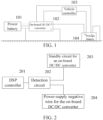
- FIG. 1 is a schematic structural diagram of a wiring circuit for a ground wire of an on-board direct current/direct current (DC/DC) converter provided in implementations of the present disclosure.
- the wiring circuit may include a power battery 101, an on-board DC/DC converter 102, a vehicle controller 103, and a storage battery 104.
- the power battery 101 is connected with the on-board DC/DC converter 102 through a high-voltage cable shielding layer.
- the on-board DC/DC converter 102 is connected with a negative electrode of the storage battery 104 through a power-supply negative wire for the on-board DC/DC converter.
- the on-board DC/DC converter 102 is connected with the vehicle controller 103 through a power-supply positive wire for the on-board DC/DC converter.
- the vehicle controller 103 is connected with a positive electrode of the storage battery 104.
- the positive electrode of the storage battery 104 is connected with the on-board DC/DC converter 102 through an on-board DC/DC positive output wire.
- the negative electrode of the storage battery 104 is connected with a vehicle frame or a vehicle body through a storage-battery ground wire.
- the on-board DC/DC converter 102 is connected with the vehicle frame or the vehicle body through a DC/DC ground wire.
- the high-voltage cable shielding layer is connected with the vehicle frame or the vehicle body through a ground wire.
- the high-voltage cable shielding layer is connected with the vehicle frame or the vehicle body to keep a shielding effect.
- the storage battery 104 is configured to supply power for the on-board DC/DC converter 102.
- the vehicle controller 103 is configured to control the on-board DC/DC converter 102 to be on or off.
- an operation principle of the wiring circuit for the ground wire of the on-board DC/DC converter illustrated in FIG 1 is as follows.
- the on-board DC/DC converter 102 is connected with the vehicle frame or the vehicle body through one DC/DC ground wire
- the storage battery 104 is connected with the vehicle frame or the vehicle body through one storage-battery ground wire.
- An output current of the on-board DC/DC converter 102 flows from the positive electrode of the on-board DC/DC converter 102 to the storage battery 104 through the on-board DC/DC positive output wire, and then flows back to the on-board DC/DC converter 102 through the storage-battery ground wire, the vehicle body or the vehicle frame, and the DC/DC ground wire.
- the storage battery 104 is required to supply power for the on-board DC/DC converter 102.
- a standby circuit is inside the on-board DC/DC converter 102, and the standby circuit has a positive input and a negative input.
- the positive input of the standby circuit is controlled by the vehicle controller 103 to be on or off, so as to control the on-board DC/DC converter 102 to be on or off.
- the negative input of the standby circuit inside the on-board DC/DC converter 102 is connected with the vehicle body by being connected with the negative electrode of the storage battery 104.
- FIG. 2 is a schematic structural diagram of a detection circuit for an on-board DC/DC ground wire provided in implementations of the present disclosure.
- the detection circuit for the on-board DC/DC ground wire includes a digital signal process (DSP) controller 201, a detection circuit 202, a standby circuit for the on-board DC/DC converter 203, and a power-supply negative wire for the on-board DC/DC converter 204.
- the DSP controller 201 is connected with the detection circuit 202.
- the detection circuit 202 is connected with the standby circuit for the on-board DC/DC converter 203 and the power-supply negative wire for the on-board DC/DC converter 204 respectively.
- the detection circuit 202 is also connected with an external input voltage.
- the DSP controller 201 may be configured to control the standby circuit for the on-board DC/DC converter 203 to increase or reduce an output current and may be configured to control an on or off state of the standby circuit for the on-board DC/DC converter 203.
- the detection circuit 202 may be configured to detect an operation of the standby circuit for the on-board DC/DC converter 203.
- the detection circuit 202 may be configured to detect the disconnection or the poor contact of the ground wire in the standby circuit for the on-board DC/DC converter 203.
- the detection circuit for the on-board DC/DC ground wire illustrated in the schematic structural diagram of FIG. 2 can detect an abnormal case of the wiring circuit of the ground wire connected with the on-board DC/DC converter 102 illustrated in FIG. 1 , such as, the disconnection or the poor contact of the ground wire.
- the detection circuit 202 is connected between the DSP controller 201 and standby circuit for the on-board DC/DC converter 203, and the detection circuit 202 is connected between the DSP controller 201 and the power-supply negative wire for the on-board DC/DC converter 204.
- the above detection circuit 202 can detect a large current in the power-supply negative wire for the on-board DC/DC converter 204 or a shielding wire due to the disconnection or the poor contact of the ground wire of the DC/DC converter 102, thereby avoiding the wiring harness from being burned up due to a continuous output of the large current and avoiding an electronic fault phenomenon of the large current.
- FIG. 3 is a schematic structural diagram of a detection circuit for an on-board DC/DC ground wire provided in other implementations of the present disclosure.
- the detection circuit includes a comparator, a first conductive branch, a second conductive branch, and a third conductive branch.
- the first conductive branch includes a resistor R1, a resistor R2, and a capacitor C1.
- the resistor R1 has one end connected with external input voltage VREF.
- the resistor R1 has another end connected with a negative input end of the comparator, one end of the resistor R2, and one end of the capacitor C1. Another end of the resistor R2 and another end of the capacitor C1 are grounded.
- the second conductive branch includes a resistor R3, a resistor R4, and a capacitor C2.
- the resistor R3 has one end connected with external input voltage VREF.
- the resistor R3 has another end connected with one end of the resistor R4, a positive input end of the comparator, and one end of the capacitor C2.
- Another end of the resistor R4 and another end of the capacitor C2 are connected with the power-supply negative wire for the on-board DC/DC converter.
- the third conductive branch includes a resistor R5.
- the resistor R5 has one end connected with the standby circuit for the on-board DC/DC converter and grounded.
- the resistor R5 has another end connected with the power-supply negative wire for the on-board DC/DC converter.
- the first conductive branch and the second conductive branch are connected with the external input voltage.
- the second conductive branch is connected with the third conductive branch and the power-supply negative wire for the on-board DC/DC converter.
- the comparator in the above detection circuit for the on-board DC/DC ground wire may include a voltage comparator, which is not specifically limited herein.
- a positive input voltage of the comparator is supplied from the external input voltage via the resistor R3 and the resistor R4, and a negative input voltage of the comparator is supplied from the external input voltage via the resistor R1 and the resistor R2.
- FIG. 4 is a schematic structural diagram of a detection circuit for an on-board DC/DC ground wire provided in other implementations of the present disclosure.
- the detection circuit for the on-board DC/DC ground wire includes a DSP controller, a detection circuit, a standby circuit for an on-board DC/DC converter, a power-supply negative wire for the on-board DC/DC converter, a storage battery, a vehicle frame, and a housing.
- the detection circuit includes a comparator, a first conductive branch, a second conductive branch, and a third conductive branch.
- the DSP controller is connected with a port 7 of the comparator in the detection circuit.
- the second conductive branch of the detection circuit is connected with an external input voltage.
- the third conductive branch of the detection circuit is connected with the standby circuit for the on-board DC/DC converter.
- the second conductive branch of the detection circuit and the third conductive branch each are connected with the power-supply negative wire for the on-board DC/DC converter.
- the above detection circuit can be connected with the housing and the vehicle frame through a second ground wire. In implementations of the present disclosure, since the housing and the vehicle frame are connected with ground in a vehicle system, a connection with the housing or the vehicle frame is equivalent to grounding.
- the above standby circuit for the on-board DC/DC converter is connected with a positive electrode of the storage battery.
- the second conductive branch and the third conductive branch of the above detection circuit are connected with a negative electrode of the storage battery through the power-supply negative wire for the on-board DC/DC converter.
- the negative electrode of the storage battery is connected with the vehicle frame through a first ground wire, and the housing in the detection circuit is connected with the vehicle frame through the second ground wire.
- the comparator includes a positive input end and a negative input end.
- the positive input end is connected with the second conductive branch, and the negative input end is connected with the first conductive branch.
- the first conductive branch includes a resistor R1, a resistor R2, and a capacitor C1.
- the resistor R1 has one end connected with external input voltage VREF.
- the resistor R1 has another end connected with the negative input end (a port 6) of the comparator, one end of the resistor R2, and one end of the capacitor C1.
- Another end of the resistor R2 and another end of the capacitor C1 are connected with the vehicle frame.
- the second conductive branch includes a resistor R3, a resistor R4, and a capacitor C2.
- the resistor R3 has one end connected with external input voltage VREF.
- the resistor R3 has another end connected with one end of the resistor R4, the positive input end (a port 5) of the comparator, and one end of the capacitor C2.
- Another end of the resistor R4 and another end of the capacitor C2 are connected with the power-supply negative wire for the on-board DC/DC converter.
- the third conductive branch includes a resistor R5.
- the resistor R5 has one end connected with the standby circuit for the on-board DC/DC converter and the housing.
- the resistor R5 has another end connected with the power-supply negative wire for the on-board DC/DC converter.
- the first conductive branch and the second conductive branch are connected with the external input voltage.
- the second conductive branch is connected with the third conductive branch and the power-supply negative wire for the on-board DC/DC converter.
- the comparator in the above detection circuit for the on-board DC/DC ground wire may include a voltage comparator, which is not specifically limited herein.
- a positive input voltage of the comparator is supplied from the external input voltage via the resistor R3 and the resistor R4, and a negative input voltage of the comparator is supplied from the external input voltage via the resistor R1 and the resistor R2.
- the above resistor R5 has a resistance at a level of milliohm, such that a normal operation of a DC/DC standby circuit will not be affected, and an abnormal operation of the DC/DC standby circuit will not occur.
- the above DSP control circuit is configured to control the standby circuit for the on-board DC/DC converter to be on or off, such that if the DC/DC ground wire is detected to be abnormal, the DSP control circuit can directly control the DC/DC converter to be off, thereby avoiding the wiring harness in the circuit from being burned out or burned up.
- the DSP control circuit is further configured to control the standby circuit for the on-board DC/DC converter to increase or reduce an output current, such that the DSP controller can control the DC/DC converter to reduce the output current if an excessive current flowing through the DC/DC ground wire or the high-voltage cable shielding layer is detected, thereby avoiding the wiring harness from being burned up due to the continuous output of the excessive current.
- an operation principle of the detection circuit for the on-board DC/DC ground wire illustrated in FIG 4 is as follows.
- the standby circuit for the on-board DC/DC converter has a very small supply current, such that a voltage drop across the power-supply negative wire for the on-board DC/DC converter is also very low, which can be regarded as the same as a low level of the vehicle body.
- a voltage of the negative input end of the comparator is higher than a voltage of the positive input end of the comparator, such that the comparator outputs a low level.
- the power-supply negative wire for the on-board DC/DC converter and the negative electrode of the storage battery are connected with the vehicle frame through the first ground wire. If the first ground wire is in poor contact with or disconnected with the vehicle frame, a relatively large current will be generated and flow back to the standby circuit for the on-board DC/DC converter through the power-supply negative wire for the on-board DC/DC converter. When the relatively large current flows through the resistor R5 with the resistance at the level of milliohm, a relatively large voltage drop can be generated, such that a voltage of the power-supply negative wire for the on-board DC/DC converter is higher than a voltage of the vehicle body or the vehicle frame.
- the positive input voltage of the comparator is higher than the negative input voltage of the comparator, and the comparator outputs a high level to the DSP controller.
- the DSP controller controls the DC/DC converter to reduce the output current or turns off the DC/DC converter, thereby avoiding the wiring harness in the vehicle system from being burned up due to the continuous output of the large current.
- the detection circuit is connected between the DSP controller and the standby circuit for the on-board DC/DC converter, and the detection circuit is connected between the DSP controller and the power-supply negative wire for the on-board DC/DC converter.
- the above detection circuit can detect a large current in the power-supply negative wire for the DC/DC converter or a shielding wire due to the disconnection or the poor contact of the ground wire of the standby circuit for the DC/DC converter, such that the DSP controller controls the standby circuit for the on-board DC/DC converter to reduce the output current or controls the standby circuit for the on-board DC/DC converter to be off.
- the above large current may mean that a device in the circuit consumes a larger current than normal, thereby avoiding the electronic fault phenomenon of the large current.
- an on-board device is provided in implementations of the present disclosure.
- the on-board device includes the detection circuit for the on-board DC/DC ground wire provided in any of the above implementations.
- the detection circuit for the on-board DC/DC ground wire in the on-board device is the same as the detection circuit for the on-board DC/DC ground wire described in any of the above implementations, and will not be repeated herein.
- the units described as separate components may or may not be physically separated, the components illustrated as units may or may not be physical units, that is, they may be in the same place or may be distributed to multiple network elements. Part or all of the units may be selected according to actual needs to achieve the purpose of the technical solutions of implementations.
- the functional units in various implementations of the present disclosure may be integrated into one processing unit, or each unit may be physically present, or two or more units may be integrated into one unit.
- the above unit integrated may be implemented in the form of hardware or in the form of a software functional unit.
Landscapes
- Engineering & Computer Science (AREA)
- Physics & Mathematics (AREA)
- General Physics & Mathematics (AREA)
- Power Engineering (AREA)
- Chemical & Material Sciences (AREA)
- Combustion & Propulsion (AREA)
- Transportation (AREA)
- Mechanical Engineering (AREA)
- Life Sciences & Earth Sciences (AREA)
- Sustainable Development (AREA)
- Sustainable Energy (AREA)
- Emergency Protection Circuit Devices (AREA)
- Dc-Dc Converters (AREA)
- Electric Propulsion And Braking For Vehicles (AREA)
Abstract
Description
- This disclosure relates to the field of electronic circuits technology, and in particular to a detection circuit for an on-board direct current/direct current (DC/DC) ground wire.
- At present, new energy vehicles have been increasingly recognized due to requirements of environmental protection, and uses of the new energy vehicles are increasingly popular. Since a new energy vehicle uses a power lithium battery to drive a motor to obtain power, a direct current generator driven by an internal combustion engine through a belt is no longer used, but is replaced by an on-board DC/DC converter.
- However, since a load of a low-voltage electric apparatus of the whole vehicle ranges from 1KW to 3KW, the on-board DC/DC converter also needs to have an ability to provide an output ranging from 1KW to 3KW, and an output current ranges from 70A to 200A. Due to a relatively large current, a required output copper cable also has a relatively large cross-sectional area, and is expensive. In order to save costs, a positive electrode of the on-board DC/DC converter is connected with a low-voltage storage battery generally through only one output wire, a negative electrode of the on-board DC/DC converter is directly connected with a vehicle frame through a nearby a ground wire, and the low-voltage storage battery is also connected with the vehicle frame through a nearby ground wire. An output current of the on-board DC/DC converter flows from the positive electrode of the on-board DC/DC converter to the low-voltage storage battery through the output wire, and then flows back to the on-board DC/DC converter through a ground wire of a negative electrode of the low-voltage storage battery, a vehicle body, and a DC/DC ground wire.
- However, this wiring manner has a side effect as follows. The low-voltage storage battery is required to supply power for the on-board DC/DC converter. A standby circuit for the on-board DC/DC converter has a positive input and a negative input. The positive input of the standby circuit is controlled by an on-board controller to be on or off to control a DC/DC to be on or off, and the negative input of the standby circuit is connected with the vehicle body by being connected with the negative electrode of the low-voltage storage battery. If the DC/DC ground wire or the ground wire of the low-voltage storage battery is in poor contact with the vehicle body, a relatively large impedance or even a disconnection may occur between the DC/DC ground wire or the ground wire of the low-voltage storage battery and the vehicle body, thereby resulting in a current of hundreds of amperes flowing back to the DC/DC through a shielding layer or a negative wire of the standby circuit. Finally, a wiring harness will be heated seriously until the wiring harness is burned up.
- A detection circuit for an on-board direct current/direct current (DC/DC) ground wire is provided in implementations of the present disclosure, which is beneficial to detecting a disconnection of a ground wire and avoiding a wiring harness from being burned up due to a continuous output of an excessive current.
- In a first aspect, a detection circuit for an on-board DC/DC ground wire is provided in implementations of the present disclosure. The detection circuit for the on-board DC/DC ground wire includes a digital signal process (DSP) controller, a detection circuit, a standby circuit for an on-board DC/DC converter, and a power-supply negative wire for the on-board DC/DC converter. The DSP controller is connected with the detection circuit. The detection circuit is connected with the standby circuit for the on-board DC/DC converter and the power-supply negative wire for the on-board DC/DC converter respectively. The detection circuit is further connected with an external input voltage. The detection circuit includes a comparator, a first conductive branch, a second conductive branch, and a third conductive branch. The comparator includes a positive input end and a negative input end. The positive input end is connected with the second conductive branch. The negative input end is connected with the first conductive branch.
- In an implementation, the first conductive branch includes a resistor R1, a resistor R2, and a capacitor C1. The resistor R1 has one end connected with the external input voltage. The resistor R1 has another end connected with the negative input end of the comparator, one end of the resistor R2, and one end of the capacitor C1. Another end of the resistor R2 and another end of the capacitor C1 are grounded.
- In an implementation, the second conductive branch includes a resistor R3, a resistor R4, and a capacitor C2. The resistor R3 has one end connected with the external input voltage. The resistor R3 has another end connected with one end of the resistor R4, the positive input end of the comparator, and one end of the capacitor C2. Another end of the resistor R4 and another end of the capacitor C2 are connected with the power-supply negative wire for the on-board DC/DC converter.
- In an implementation, the third conductive branch includes a resistor R5. The resistor R5 has one end connected with the standby circuit for the on-board DC/DC converter and grounded. The resistor R5 has another end connected with the power-supply negative wire for the on-board DC/DC converter.
- In an implementation, the first conductive branch and the second conductive branch are connected with the external input voltage. The second conductive branch is connected with the third conductive branch and the power-supply negative wire for the on-board DC/DC converter.
- In an implementation, the comparator is a voltage comparator. A positive input voltage of the comparator is supplied from the external input voltage via a resistor R3 and a resistor R4, and a negative input voltage of the comparator is supplied from the external input voltage via a resistor R1 and a resistor R2.
- In an implementation, a DSP control circuit is configured to control the standby circuit for the on-board DC/DC converter to be on or off.
- In an implementation, the DSP control circuit is further configured to control the standby circuit for the on-board DC/DC converter to increase or reduce an output current.
- In a second aspect, an on-board device is provided in the present disclosure. The on-board device includes the detection circuit for the on-board DC/DC ground wire of the first aspect of implementations of the present disclosure.
- In implementations of the present disclosure, the detection circuit for the on-board DC/DC ground wire includes the DSP controller, the detection circuit, the standby circuit for the on-board DC/DC converter, and the power-supply negative wire for the on-board DC/DC converter. The DSP controller is connected with the detection circuit. The detection circuit is connected with the standby circuit for the on-board DC/DC converter and the power-supply negative wire for the on-board DC/DC converter respectively. The detection circuit is further connected with the external input voltage. The detection circuit includes the comparator, the first conductive branch, the second conductive branch, and the third conductive branch. The comparator includes the positive input end and the negative input end. The positive input end is connected with the second conductive branch. The negative input end is connected with the first conductive branch. In this way, the detection circuit is connected between the DSP controller and the standby circuit for the on-board DC/DC converter, and the detection circuit is connected between the DSP controller and the power-supply negative wire for the on-board DC/DC converter. Once the ground wire of the DC/DC converter is in poor contact with or even disconnected with the vehicle body, or the ground wire of the low-voltage storage battery is in poor contact with or even disconnected with the vehicle body, a current of hundreds of amperes is generated, the detection circuit can detect a large current in the power-supply negative wire for the on-board DC/DC converter due to a disconnection or a poor contact of the ground wire of the DC/DC converter, thereby avoiding the wiring harness from being burned up due to the continuous output of the large current.
- In order to more clearly explain technical situations in implementations or the related art of the present disclosure, the following will briefly introduce accompanying drawings involved in implementations or the related art of the present disclosure.
-
FIG. 1 is a schematic structural diagram of a wiring circuit for a ground wire of an on-board direct current/direct current (DC/DC) converter provided in implementations of the present disclosure. -
FIG. 2 is a schematic structural diagram of a detection circuit for an on-board DC/DC ground wire provided in implementations of the present disclosure. -
FIG. 3 is a schematic structural diagram of a detection circuit for an on-board DC/DC ground wire provided in other implementations of the present disclosure. -
FIG. 4 is a schematic structural diagram of a detection circuit for an on-board DC/DC ground wire provided in other implementations of the present disclosure. - In order to make those skilled in the art better understand technical solutions of the present disclosure, technical solutions of implementations of the present disclosure will be described clearly and completely with reference to accompanying drawings in implementations. Apparently, implementations described hereinafter are merely some implementations, rather than all implementations of the present disclosure. All other implementations obtained by those of ordinary skill in the art based on implementations without creative efforts shall fall within the protection scope of the present disclosure.
- The terms "first", "second", and the like used in the specification, the claims, and the accompany drawings of the present disclosure are used to distinguish different objects rather than describe a particular order. The terms "include", "comprise", and "have" as well as variations thereof are intended to cover non-exclusive inclusion. For example, a process, system, product, or device including a series of steps or units is not limited to the listed steps or units, on the contrary, it can optionally include other steps or units that are not listed; alternatively, other steps or units inherent to the process, product, or device can be included either.
- The term "implementation" referred to herein means that particular features, structures, or properties described in conjunction with implementations may be defined in at least one implementation of the present disclosure. The phrase "implementation" appearing in various places in the specification does not necessarily refer to the same implementation or an independent/ alternative implementation that is mutually exclusive with other implementations. Those skilled in the art will understand expressly and implicitly that an implementation described herein may be combined with other implementations.
- In order to better explain implementations of the present disclosure, a large current in implementations of the present disclosure may mean that an electronic component in a circuit consumes a larger current than normal, and a range of the large current has exceeded a standard current, which is an electronic fault phenomenon.
- Reference can be made to
FIG. 1 , which is a schematic structural diagram of a wiring circuit for a ground wire of an on-board direct current/direct current (DC/DC) converter provided in implementations of the present disclosure. The wiring circuit may include apower battery 101, an on-board DC/DC converter 102, avehicle controller 103, and astorage battery 104. Thepower battery 101 is connected with the on-board DC/DC converter 102 through a high-voltage cable shielding layer. The on-board DC/DC converter 102 is connected with a negative electrode of thestorage battery 104 through a power-supply negative wire for the on-board DC/DC converter. The on-board DC/DC converter 102 is connected with thevehicle controller 103 through a power-supply positive wire for the on-board DC/DC converter. Thevehicle controller 103 is connected with a positive electrode of thestorage battery 104. The positive electrode of thestorage battery 104 is connected with the on-board DC/DC converter 102 through an on-board DC/DC positive output wire. The negative electrode of thestorage battery 104 is connected with a vehicle frame or a vehicle body through a storage-battery ground wire. The on-board DC/DC converter 102 is connected with the vehicle frame or the vehicle body through a DC/DC ground wire. The high-voltage cable shielding layer is connected with the vehicle frame or the vehicle body through a ground wire. The high-voltage cable shielding layer is connected with the vehicle frame or the vehicle body to keep a shielding effect. Thestorage battery 104 is configured to supply power for the on-board DC/DC converter 102. Thevehicle controller 103 is configured to control the on-board DC/DC converter 102 to be on or off. - Optionally, an operation principle of the wiring circuit for the ground wire of the on-board DC/DC converter illustrated in
FIG 1 is as follows. In normal cases, the on-board DC/DC converter 102 is connected with the vehicle frame or the vehicle body through one DC/DC ground wire, and thestorage battery 104 is connected with the vehicle frame or the vehicle body through one storage-battery ground wire. An output current of the on-board DC/DC converter 102 flows from the positive electrode of the on-board DC/DC converter 102 to thestorage battery 104 through the on-board DC/DC positive output wire, and then flows back to the on-board DC/DC converter 102 through the storage-battery ground wire, the vehicle body or the vehicle frame, and the DC/DC ground wire. - In the wiring circuit illustrated in
FIG. 1 , thestorage battery 104 is required to supply power for the on-board DC/DC converter 102. In the meanwhile, a standby circuit is inside the on-board DC/DC converter 102, and the standby circuit has a positive input and a negative input. The positive input of the standby circuit is controlled by thevehicle controller 103 to be on or off, so as to control the on-board DC/DC converter 102 to be on or off. The negative input of the standby circuit inside the on-board DC/DC converter 102 is connected with the vehicle body by being connected with the negative electrode of thestorage battery 104. In abnormal cases, if the DC/DC ground wire is in poor contact with the vehicle body or the vehicle frame, or the storage-battery ground wire of thestorage battery 104 is in poor contact with the vehicle body or the vehicle frame, a relatively large impedance or even a disconnection of the storage-battery ground wire may occur between the DC/DC ground wire or the storage-battery ground wire of thestorage battery 104 and the vehicle body or the vehicle frame. Finally, a current of hundreds of amperes flowing back to the on-board DC/DC converter 102 through the high-voltage cable shielding layer or a negative wire of the standby circuit for the on-board DC/DC converter 102, thereby resulting in severe heating of the wiring harness until the wiring harness is burned up. - Implementations of the present disclosure are described in detail below in combination with the accompanying drawings.
- Reference can be made to
FIG. 2 , which is a schematic structural diagram of a detection circuit for an on-board DC/DC ground wire provided in implementations of the present disclosure. The detection circuit for the on-board DC/DC ground wire includes a digital signal process (DSP)controller 201, adetection circuit 202, a standby circuit for the on-board DC/DC converter 203, and a power-supply negative wire for the on-board DC/DC converter 204. TheDSP controller 201 is connected with thedetection circuit 202. Thedetection circuit 202 is connected with the standby circuit for the on-board DC/DC converter 203 and the power-supply negative wire for the on-board DC/DC converter 204 respectively. Thedetection circuit 202 is also connected with an external input voltage. - In addition, the
DSP controller 201 may be configured to control the standby circuit for the on-board DC/DC converter 203 to increase or reduce an output current and may be configured to control an on or off state of the standby circuit for the on-board DC/DC converter 203. Thedetection circuit 202 may be configured to detect an operation of the standby circuit for the on-board DC/DC converter 203. For example, thedetection circuit 202 may be configured to detect the disconnection or the poor contact of the ground wire in the standby circuit for the on-board DC/DC converter 203. - Optionally, the detection circuit for the on-board DC/DC ground wire illustrated in the schematic structural diagram of
FIG. 2 can detect an abnormal case of the wiring circuit of the ground wire connected with the on-board DC/DC converter 102 illustrated inFIG. 1 , such as, the disconnection or the poor contact of the ground wire. Specifically, in implementations of the present disclosure, thedetection circuit 202 is connected between theDSP controller 201 and standby circuit for the on-board DC/DC converter 203, and thedetection circuit 202 is connected between theDSP controller 201 and the power-supply negative wire for the on-board DC/DC converter 204. Once the ground wire of the DC/DC converter 102 is in poor contact with or even disconnected with the vehicle body, or the ground wire of the storage battery is in poor contact with or even disconnected with the vehicle body, a current of hundreds of amperes is generated, theabove detection circuit 202 can detect a large current in the power-supply negative wire for the on-board DC/DC converter 204 or a shielding wire due to the disconnection or the poor contact of the ground wire of the DC/DC converter 102, thereby avoiding the wiring harness from being burned up due to a continuous output of the large current and avoiding an electronic fault phenomenon of the large current. - Reference can be made to
FIG. 3 , which is a schematic structural diagram of a detection circuit for an on-board DC/DC ground wire provided in other implementations of the present disclosure. The detection circuit includes a comparator, a first conductive branch, a second conductive branch, and a third conductive branch. - Optionally, the first conductive branch includes a resistor R1, a resistor R2, and a capacitor C1. The resistor R1 has one end connected with external input voltage VREF. The resistor R1 has another end connected with a negative input end of the comparator, one end of the resistor R2, and one end of the capacitor C1. Another end of the resistor R2 and another end of the capacitor C1 are grounded.
- Optionally, the second conductive branch includes a resistor R3, a resistor R4, and a capacitor C2. The resistor R3 has one end connected with external input voltage VREF. The resistor R3 has another end connected with one end of the resistor R4, a positive input end of the comparator, and one end of the capacitor C2. Another end of the resistor R4 and another end of the capacitor C2 are connected with the power-supply negative wire for the on-board DC/DC converter.
- Optionally, the third conductive branch includes a resistor R5. The resistor R5 has one end connected with the standby circuit for the on-board DC/DC converter and grounded. The resistor R5 has another end connected with the power-supply negative wire for the on-board DC/DC converter.
- Optionally, the first conductive branch and the second conductive branch are connected with the external input voltage. The second conductive branch is connected with the third conductive branch and the power-supply negative wire for the on-board DC/DC converter.
- Optionally, the comparator in the above detection circuit for the on-board DC/DC ground wire may include a voltage comparator, which is not specifically limited herein. A positive input voltage of the comparator is supplied from the external input voltage via the resistor R3 and the resistor R4, and a negative input voltage of the comparator is supplied from the external input voltage via the resistor R1 and the resistor R2.
- Reference can be made to
FIG. 4 , which is a schematic structural diagram of a detection circuit for an on-board DC/DC ground wire provided in other implementations of the present disclosure. The detection circuit for the on-board DC/DC ground wire includes a DSP controller, a detection circuit, a standby circuit for an on-board DC/DC converter, a power-supply negative wire for the on-board DC/DC converter, a storage battery, a vehicle frame, and a housing. The detection circuit includes a comparator, a first conductive branch, a second conductive branch, and a third conductive branch. - Optionally, the DSP controller is connected with a
port 7 of the comparator in the detection circuit. The second conductive branch of the detection circuit is connected with an external input voltage. The third conductive branch of the detection circuit is connected with the standby circuit for the on-board DC/DC converter. The second conductive branch of the detection circuit and the third conductive branch each are connected with the power-supply negative wire for the on-board DC/DC converter. The above detection circuit can be connected with the housing and the vehicle frame through a second ground wire. In implementations of the present disclosure, since the housing and the vehicle frame are connected with ground in a vehicle system, a connection with the housing or the vehicle frame is equivalent to grounding. - Optionally, the above standby circuit for the on-board DC/DC converter is connected with a positive electrode of the storage battery. The second conductive branch and the third conductive branch of the above detection circuit are connected with a negative electrode of the storage battery through the power-supply negative wire for the on-board DC/DC converter. The negative electrode of the storage battery is connected with the vehicle frame through a first ground wire, and the housing in the detection circuit is connected with the vehicle frame through the second ground wire.
- The comparator includes a positive input end and a negative input end. The positive input end is connected with the second conductive branch, and the negative input end is connected with the first conductive branch.
- Optionally, the first conductive branch includes a resistor R1, a resistor R2, and a capacitor C1. The resistor R1 has one end connected with external input voltage VREF. The resistor R1 has another end connected with the negative input end (a port 6) of the comparator, one end of the resistor R2, and one end of the capacitor C1. Another end of the resistor R2 and another end of the capacitor C1 are connected with the vehicle frame.
- Optionally, the second conductive branch includes a resistor R3, a resistor R4, and a capacitor C2. The resistor R3 has one end connected with external input voltage VREF. The resistor R3 has another end connected with one end of the resistor R4, the positive input end (a port 5) of the comparator, and one end of the capacitor C2. Another end of the resistor R4 and another end of the capacitor C2 are connected with the power-supply negative wire for the on-board DC/DC converter.
- Optionally, the third conductive branch includes a resistor R5. The resistor R5 has one end connected with the standby circuit for the on-board DC/DC converter and the housing. The resistor R5 has another end connected with the power-supply negative wire for the on-board DC/DC converter.
- Optionally, the first conductive branch and the second conductive branch are connected with the external input voltage. The second conductive branch is connected with the third conductive branch and the power-supply negative wire for the on-board DC/DC converter.
- Optionally, the comparator in the above detection circuit for the on-board DC/DC ground wire may include a voltage comparator, which is not specifically limited herein. A positive input voltage of the comparator is supplied from the external input voltage via the resistor R3 and the resistor R4, and a negative input voltage of the comparator is supplied from the external input voltage via the resistor R1 and the resistor R2.
- Optionally, the above resistor R5 has a resistance at a level of milliohm, such that a normal operation of a DC/DC standby circuit will not be affected, and an abnormal operation of the DC/DC standby circuit will not occur.
- Optionally, the above DSP control circuit is configured to control the standby circuit for the on-board DC/DC converter to be on or off, such that if the DC/DC ground wire is detected to be abnormal, the DSP control circuit can directly control the DC/DC converter to be off, thereby avoiding the wiring harness in the circuit from being burned out or burned up.
- Optionally, the DSP control circuit is further configured to control the standby circuit for the on-board DC/DC converter to increase or reduce an output current, such that the DSP controller can control the DC/DC converter to reduce the output current if an excessive current flowing through the DC/DC ground wire or the high-voltage cable shielding layer is detected, thereby avoiding the wiring harness from being burned up due to the continuous output of the excessive current.
- Optionally, an operation principle of the detection circuit for the on-board DC/DC ground wire illustrated in
FIG 4 is as follows. During normal operation, the standby circuit for the on-board DC/DC converter has a very small supply current, such that a voltage drop across the power-supply negative wire for the on-board DC/DC converter is also very low, which can be regarded as the same as a low level of the vehicle body. In implementations of the present disclosure, by setting resistances of the resistor R1, the resistor R2, the resistor R3, and the resistor R4, a voltage of the negative input end of the comparator is higher than a voltage of the positive input end of the comparator, such that the comparator outputs a low level. The power-supply negative wire for the on-board DC/DC converter and the negative electrode of the storage battery are connected with the vehicle frame through the first ground wire. If the first ground wire is in poor contact with or disconnected with the vehicle frame, a relatively large current will be generated and flow back to the standby circuit for the on-board DC/DC converter through the power-supply negative wire for the on-board DC/DC converter. When the relatively large current flows through the resistor R5 with the resistance at the level of milliohm, a relatively large voltage drop can be generated, such that a voltage of the power-supply negative wire for the on-board DC/DC converter is higher than a voltage of the vehicle body or the vehicle frame. Finally, the positive input voltage of the comparator is higher than the negative input voltage of the comparator, and the comparator outputs a high level to the DSP controller. Here, the DSP controller controls the DC/DC converter to reduce the output current or turns off the DC/DC converter, thereby avoiding the wiring harness in the vehicle system from being burned up due to the continuous output of the large current. - It can be seen that in implementations of the present disclosure, the detection circuit is connected between the DSP controller and the standby circuit for the on-board DC/DC converter, and the detection circuit is connected between the DSP controller and the power-supply negative wire for the on-board DC/DC converter. Once the ground wire connected with the power-supply negative wire for the on-board DC/DC converter is in poor contact with or even disconnected with the vehicle body, or the ground wire of the low-voltage storage battery is in poor contact with or even disconnected with the vehicle body, a current of hundreds of amperes is generated, the above detection circuit can detect a large current in the power-supply negative wire for the DC/DC converter or a shielding wire due to the disconnection or the poor contact of the ground wire of the standby circuit for the DC/DC converter, such that the DSP controller controls the standby circuit for the on-board DC/DC converter to reduce the output current or controls the standby circuit for the on-board DC/DC converter to be off. The above large current may mean that a device in the circuit consumes a larger current than normal, thereby avoiding the electronic fault phenomenon of the large current.
- In a possible implementation, an on-board device is provided in implementations of the present disclosure. The on-board device includes the detection circuit for the on-board DC/DC ground wire provided in any of the above implementations. The detection circuit for the on-board DC/DC ground wire in the on-board device is the same as the detection circuit for the on-board DC/DC ground wire described in any of the above implementations, and will not be repeated herein.
- It should be noted that for the sake of simplicity, the above implementations of the present disclosure are described as a series of action combinations. However, it will be appreciated by those skilled in the art that implementations are not limited by the sequence of actions described. According to implementations, some steps or operations may be performed in other orders or simultaneously. Besides, it will be appreciated by those skilled in the art that implementations described in the specification are exemplary implementations, and the actions and modules involved are not necessarily essential to the present disclosure.
- In the above implementations, the description of each implementation has its own emphasis. For the parts not described in detail in one implementation, reference may be made to related descriptions in other implementations.
- In implementations of the present disclosure, it should be understood that the apparatus disclosed in implementations provided in the present disclosure may be implemented in other manners. For example, the device/apparatus implementations described above are merely illustrative; for instance, the division of the unit is only a logical function division and there can be other manners of division during actual implementations, for example, multiple units or assemblies may be combined or may be integrated into another system, or some features may be ignored, omitted, or not performed. In addition, coupling or communication connection between each illustrated or discussed component may be direct coupling or communication connection, or may be indirect coupling or communication among devices or units via some interfaces, and may be electrical connection or other forms of connection.
- The units described as separate components may or may not be physically separated, the components illustrated as units may or may not be physical units, that is, they may be in the same place or may be distributed to multiple network elements. Part or all of the units may be selected according to actual needs to achieve the purpose of the technical solutions of implementations.
- In addition, the functional units in various implementations of the present disclosure may be integrated into one processing unit, or each unit may be physically present, or two or more units may be integrated into one unit. The above unit integrated may be implemented in the form of hardware or in the form of a software functional unit.
- The above implementations in the present disclosure are described in detail. Principles and implementations of the present disclosure are elaborated with specific implementations herein. The above illustration of implementations is only used to help to understand methods and core ideas of the present disclosure. In the meanwhile, for those of ordinary skill in the art, according to ideas of the present disclosure, there will be changes in specific implementation manners and application scope. To sum up, contents of this specification should not be understood as limitation on the present disclosure.
Claims (10)
- A detection circuit for an on-board direct current/direct current (DC/DC) ground wire, comprising a digital signal process (DSP) controller, a detection circuit, a standby circuit for an on-board DC/DC converter, and a power-supply negative wire for the on-board DC/DC converter, whereinthe DSP controller is connected with the detection circuit, the detection circuit is connected with the standby circuit for the on-board DC/DC converter and the power-supply negative wire for the on-board DC/DC converter respectively, and the detection circuit is further connected with an external input voltage;the detection circuit comprises a comparator, a first conductive branch, a second conductive branch, and a third conductive branch; andthe comparator comprises a positive input end and a negative input end, the positive input end is connected with the second conductive branch, and the negative input end is connected with the first conductive branch.
- The detection circuit for the on-board DC/DC ground wire of claim 1, wherein the first conductive branch comprises a resistor R1, a resistor R2, and a capacitor C1, wherein
the resistor R1 has one end connected with the external input voltage, the resistor R1 has another end connected with the negative input end of the comparator, one end of the resistor R2, and one end of the capacitor C1, and another end of the resistor R2 and another end of the capacitor C1 are grounded. - The detection circuit for the on-board DC/DC ground wire of claim 1, wherein the second conductive branch comprises a resistor R3, a resistor R4, and a capacitor C2, wherein
the resistor R3 has one end connected with the external input voltage, the resistor R3 has another end connected with one end of the resistor R4, the positive input end of the comparator, and one end of the capacitor C2, and another end of the resistor R4 and another end of the capacitor C2 are connected with the power-supply negative wire for the on-board DC/DC converter. - The detection circuit for the on-board DC/DC ground wire of claim 1, wherein the third conductive branch comprises a resistor R5, wherein
the resistor R5 has one end connected with the standby circuit for the on-board DC/DC converter and a housing, and the resistor R5 has another end connected with the power-supply negative wire for the on-board DC/DC converter. - The detection circuit for the on-board DC/DC ground wire of any of claims 1 to 4, wherein
the first conductive branch and the second conductive branch are connected with the external input voltage, and the second conductive branch is connected with the third conductive branch and the power-supply negative wire for the on-board DC/DC converter. - The detection circuit for the on-board DC/DC ground wire of any of claims 1 to 3, wherein the comparator is a voltage comparator, wherein
a positive input voltage of the comparator is supplied from the external input voltage via a resistor R3 and a resistor R4, and a negative input voltage of the comparator is supplied from the external input voltage via a resistor R1 and a resistor R2. - The detection circuit for the on-board DC/DC ground wire of claim 4, wherein the resistor R5 has a resistance at a level of milliohm.
- The detection circuit for the on-board DC/DC ground wire of claim 1, wherein a DSP control circuit is configured to control the standby circuit for the on-board DC/DC converter to be on or off.
- The detection circuit for the on-board DC/DC ground wire of claim 8, wherein the DSP control circuit is further configured to control the standby circuit for the on-board DC/DC converter to increase or decrease an output current.
- An on-board device, comprising the detection circuit for the on-board DC/DC ground wire of any of claims 1 to 9.
Applications Claiming Priority (1)
| Application Number | Priority Date | Filing Date | Title |
|---|---|---|---|
| PCT/CN2020/101311 WO2022006845A1 (en) | 2020-07-10 | 2020-07-10 | Vehicle-mounted dc/dc bond strap detection circuit |
Publications (2)
| Publication Number | Publication Date |
|---|---|
| EP4186732A1 true EP4186732A1 (en) | 2023-05-31 |
| EP4186732A4 EP4186732A4 (en) | 2023-11-15 |
Family
ID=76344784
Family Applications (1)
| Application Number | Title | Priority Date | Filing Date |
|---|---|---|---|
| EP20943999.1A Pending EP4186732A4 (en) | 2020-07-10 | 2020-07-10 | Vehicle-mounted dc/dc bond strap detection circuit |
Country Status (4)
| Country | Link |
|---|---|
| US (1) | US12099098B2 (en) |
| EP (1) | EP4186732A4 (en) |
| CN (1) | CN112997090B (en) |
| WO (1) | WO2022006845A1 (en) |
Families Citing this family (3)
| Publication number | Priority date | Publication date | Assignee | Title |
|---|---|---|---|---|
| JP7632112B2 (en) | 2021-06-24 | 2025-02-19 | トヨタ自動車株式会社 | Power System |
| CN115684795B (en) * | 2022-10-31 | 2026-01-23 | 创联新能源科技(深圳)有限公司 | Comprehensive detector for vehicle-mounted charger and direct-current power supply converter of electric automobile |
| CN118731771B (en) * | 2024-06-25 | 2025-12-05 | 中国第一汽车股份有限公司 | Ground loop test methods, apparatus and electronic equipment |
Family Cites Families (12)
| Publication number | Priority date | Publication date | Assignee | Title |
|---|---|---|---|---|
| JP3307173B2 (en) * | 1995-03-20 | 2002-07-24 | 松下電器産業株式会社 | Earth leakage detection device |
| US6977518B2 (en) * | 2002-11-11 | 2005-12-20 | Matsushita Electric Works, Ltd. | Electrical leak detecting apparatus |
| EP2011685B1 (en) * | 2006-04-25 | 2020-01-15 | Mitsubishi Denki Kabushiki Kaisha | Control device for electric vehicle |
| JP4365847B2 (en) * | 2006-10-24 | 2009-11-18 | 三菱電機株式会社 | In-vehicle electric load power supply control device |
| CN101604282B (en) * | 2008-06-13 | 2012-08-29 | 鸿富锦精密工业(深圳)有限公司 | Voltage detection alarm device |
| JPWO2012157036A1 (en) * | 2011-05-13 | 2014-07-31 | トヨタ自動車株式会社 | Vehicle power system |
| CN104635141B (en) * | 2015-01-30 | 2018-07-03 | 华为技术有限公司 | A kind of integrated circuit detection method, apparatus and system |
| KR102522608B1 (en) * | 2016-11-18 | 2023-04-17 | 현대모비스 주식회사 | Apparatus of detecting a leakage current of high-power inverter for 48V mild hybrid and the method thereof |
| CN206583996U (en) * | 2016-11-25 | 2017-10-24 | 上海荣威塑胶工业有限公司 | Ground detection device and pond system |
| JP6711462B2 (en) * | 2017-07-18 | 2020-06-17 | 東芝三菱電機産業システム株式会社 | Ground fault detector and power conditioner |
| CN207677430U (en) * | 2018-01-18 | 2018-07-31 | 苏州超云新能源有限公司 | inverter leakage protection circuit and inverter |
| CN213354193U (en) * | 2020-07-10 | 2021-06-04 | 深圳欣锐科技股份有限公司 | A vehicle-mounted DC/DC ground wire detection circuit and vehicle-mounted equipment |
-
2020
- 2020-07-10 EP EP20943999.1A patent/EP4186732A4/en active Pending
- 2020-07-10 CN CN202080006016.7A patent/CN112997090B/en active Active
- 2020-07-10 WO PCT/CN2020/101311 patent/WO2022006845A1/en not_active Ceased
-
2023
- 2023-01-09 US US18/094,531 patent/US12099098B2/en active Active
Also Published As
| Publication number | Publication date |
|---|---|
| EP4186732A4 (en) | 2023-11-15 |
| CN112997090B (en) | 2022-12-23 |
| CN112997090A (en) | 2021-06-18 |
| WO2022006845A1 (en) | 2022-01-13 |
| US20230160976A1 (en) | 2023-05-25 |
| US12099098B2 (en) | 2024-09-24 |
Similar Documents
| Publication | Publication Date | Title |
|---|---|---|
| US12099098B2 (en) | Detection circuit for on-board direct current/direct current (DC/DC) ground wire and on-board device | |
| TWI453432B (en) | Insulating detection circuit and method thereof | |
| WO2010113927A1 (en) | Electric vehicle charger and ground fault detection method | |
| CN108695692B (en) | A highly integrated anti-electromagnetic shielding high-voltage distribution box | |
| CN1072407C (en) | Charging terminal shortcircuit preventing circuit for battery pack | |
| EP2840405A1 (en) | In-vehicle power supply apparatus | |
| US9321360B2 (en) | Electronic control unit | |
| CN105958629A (en) | BMS power supply device and power supply method for electric automobile | |
| CN106936183B (en) | Power supply control circuit, electric vehicle charging guide circuit and charging pile | |
| CN213354193U (en) | A vehicle-mounted DC/DC ground wire detection circuit and vehicle-mounted equipment | |
| CN207388881U (en) | A battery management system CAN communication circuit | |
| CN115700185A (en) | Relay control system and battery system | |
| JP5947518B2 (en) | Electronic control unit | |
| KR20250085323A (en) | Electric vehicle charging controller and charging control method of the same | |
| KR20250085395A (en) | Electric vehicle charging controller and charging control method of the same | |
| CN210912091U (en) | Battery management unit for sending pulse width modulation signal to detect high-voltage interlock | |
| CN223462951U (en) | High-voltage motor controller circuit board | |
| CN115768650A (en) | Power supply system | |
| US11600991B2 (en) | Electrical circuit arrangement for an energy storage system and method for operating said electrical circuit arrangement | |
| CN224068376U (en) | Battery charging and discharging architecture, vehicle power distribution architecture and vehicle | |
| CN112217181B (en) | Power protection method and circuit for electronic device | |
| CN111463859A (en) | Control method of battery parallel system and battery parallel system | |
| CN223680742U (en) | Surge current suppressing circuit and vehicle-mounted charger | |
| US20210057902A1 (en) | Power protection method and circuit for electronic device | |
| JP5814742B2 (en) | Electronic control unit |
Legal Events
| Date | Code | Title | Description |
|---|---|---|---|
| STAA | Information on the status of an ep patent application or granted ep patent |
Free format text: STATUS: THE INTERNATIONAL PUBLICATION HAS BEEN MADE |
|
| PUAI | Public reference made under article 153(3) epc to a published international application that has entered the european phase |
Free format text: ORIGINAL CODE: 0009012 |
|
| STAA | Information on the status of an ep patent application or granted ep patent |
Free format text: STATUS: REQUEST FOR EXAMINATION WAS MADE |
|
| 17P | Request for examination filed |
Effective date: 20230113 |
|
| AK | Designated contracting states |
Kind code of ref document: A1 Designated state(s): AL AT BE BG CH CY CZ DE DK EE ES FI FR GB GR HR HU IE IS IT LI LT LU LV MC MK MT NL NO PL PT RO RS SE SI SK SM TR |
|
| DAV | Request for validation of the european patent (deleted) | ||
| DAX | Request for extension of the european patent (deleted) | ||
| A4 | Supplementary search report drawn up and despatched |
Effective date: 20231013 |
|
| RIC1 | Information provided on ipc code assigned before grant |
Ipc: B60L 53/22 20190101ALI20231009BHEP Ipc: B60L 9/12 20060101ALI20231009BHEP Ipc: B60L 3/00 20190101AFI20231009BHEP |