EP4186726A1 - Verfahren zur herstellung eines verdeckbezugs eines faltverdecks für ein cabriolet-fahrzeug sowie faltverdeck für ein cabriolet-fahrzeug - Google Patents
Verfahren zur herstellung eines verdeckbezugs eines faltverdecks für ein cabriolet-fahrzeug sowie faltverdeck für ein cabriolet-fahrzeug Download PDFInfo
- Publication number
- EP4186726A1 EP4186726A1 EP22205350.6A EP22205350A EP4186726A1 EP 4186726 A1 EP4186726 A1 EP 4186726A1 EP 22205350 A EP22205350 A EP 22205350A EP 4186726 A1 EP4186726 A1 EP 4186726A1
- Authority
- EP
- European Patent Office
- Prior art keywords
- top cover
- profile
- edge
- edging
- seam
- Prior art date
- Legal status (The legal status is an assumption and is not a legal conclusion. Google has not performed a legal analysis and makes no representation as to the accuracy of the status listed.)
- Granted
Links
Images


Classifications
-
- B—PERFORMING OPERATIONS; TRANSPORTING
- B60—VEHICLES IN GENERAL
- B60J—WINDOWS, WINDSCREENS, NON-FIXED ROOFS, DOORS, OR SIMILAR DEVICES FOR VEHICLES; REMOVABLE EXTERNAL PROTECTIVE COVERINGS SPECIALLY ADAPTED FOR VEHICLES
- B60J7/00—Non-fixed roofs; Roofs with movable panels, e.g. rotary sunroofs
- B60J7/0084—Water draining for non-fixed roofs or roof panels
-
- B—PERFORMING OPERATIONS; TRANSPORTING
- B60—VEHICLES IN GENERAL
- B60J—WINDOWS, WINDSCREENS, NON-FIXED ROOFS, DOORS, OR SIMILAR DEVICES FOR VEHICLES; REMOVABLE EXTERNAL PROTECTIVE COVERINGS SPECIALLY ADAPTED FOR VEHICLES
- B60J7/00—Non-fixed roofs; Roofs with movable panels, e.g. rotary sunroofs
- B60J7/08—Non-fixed roofs; Roofs with movable panels, e.g. rotary sunroofs of non-sliding type, i.e. movable or removable roofs or panels, e.g. let-down tops or roofs capable of being easily detached or of assuming a collapsed or inoperative position
- B60J7/12—Non-fixed roofs; Roofs with movable panels, e.g. rotary sunroofs of non-sliding type, i.e. movable or removable roofs or panels, e.g. let-down tops or roofs capable of being easily detached or of assuming a collapsed or inoperative position foldable; Tensioning mechanisms therefor, e.g. struts
- B60J7/1226—Soft tops for convertible vehicles
-
- B—PERFORMING OPERATIONS; TRANSPORTING
- B60—VEHICLES IN GENERAL
- B60J—WINDOWS, WINDSCREENS, NON-FIXED ROOFS, DOORS, OR SIMILAR DEVICES FOR VEHICLES; REMOVABLE EXTERNAL PROTECTIVE COVERINGS SPECIALLY ADAPTED FOR VEHICLES
- B60J7/00—Non-fixed roofs; Roofs with movable panels, e.g. rotary sunroofs
- B60J7/08—Non-fixed roofs; Roofs with movable panels, e.g. rotary sunroofs of non-sliding type, i.e. movable or removable roofs or panels, e.g. let-down tops or roofs capable of being easily detached or of assuming a collapsed or inoperative position
- B60J7/12—Non-fixed roofs; Roofs with movable panels, e.g. rotary sunroofs of non-sliding type, i.e. movable or removable roofs or panels, e.g. let-down tops or roofs capable of being easily detached or of assuming a collapsed or inoperative position foldable; Tensioning mechanisms therefor, e.g. struts
- B60J7/1226—Soft tops for convertible vehicles
- B60J7/1234—Soft tops for convertible vehicles characterised by arches, e.g. shape or material
- B60J7/1252—Soft tops for convertible vehicles characterised by arches, e.g. shape or material characterised by lateral arches
Definitions
- the invention relates to a method for producing a top cover for a folding top for a convertible vehicle and a folding top for a convertible vehicle.
- folding tops of this type have a multi-layer structure and include an outer top cover, usually a middle padding or insulating mat and a roof liner facing the interior.
- the upholstery and insulating mat not only ensures acoustic and thermal insulation, but also supports the beautiful shape of the folding top.
- an upholstery mat is provided, it is designed as a separate layer and is partially attached to the outer fabric of the convertible top. In this way, in the closed position of the folding top, the padding mat rests sufficiently against the fabric of the top. In the closed position, the top cover material and the upholstery mat are carried by the top components and span the passenger compartment.
- the adjustable folding top extends from a windshield frame (not shown) arranged on the front, the so-called A-pillar, into a rear region of the vehicle. In a four-seater, this is the C-pillar.
- the folding top is constructed symmetrically in relation to a central axis.
- the edge areas of the top cover are usually bordered with a binding tape, with a welt forming a rain gutter also being sewn onto the top cover in the side areas of the top cover by means of the binding tape.
- a disadvantage of this design of the side areas by means of the edging with sewn The rain gutter is the visible seam required for this on the visible side of the soft top fabric. If there are deviations in the sewing process on the finished folding top, this visible seam appears to be visually unappealing. Furthermore, the sewing thread fades with the service life and the influence of weather conditions, which is also perceived as visually disturbing.
- this object is achieved by the features specified in claim 1 .
- the folding top according to the invention is essentially based on an arrangement of a strip-shaped edging and a rubber-elastic or flexible strip-shaped profile on a lower edge of the top cover, with the edging enclosing the profile in the shape of a pocket and being fixed to the top cover via a first and second seam that is not visible when viewed from the outside is.
- a top cover of a folding top for a convertible vehicle can be produced in such a way that it has an improved visual appearance due to no visible seams on the visible side of the top cover.
- a rain gutter can be produced that easily adapts to the folding movement of the folding top during an adjustment movement between the open and closed position and ensures reliable water management in the lateral edge area of the folding top.
- the gutter is realized by an elastic, strip-shaped insert.
- the strip-shaped, elastic insert is advantageously made of a plastic such as ethylene-propylene-diene rubber (EPDM).
- EPDM ethylene-propylene-diene rubber
- the x, y, z direction corresponds to the directions of a standard vehicle coordinate system, in which x denotes the longitudinal direction of the vehicle, y denotes the transverse direction and z denotes the vertical direction.
- a folding top 1 for an open motor vehicle, a convertible is shown as an example.
- the cabriolet has a body, which is not shown in the illustration, on which a folding top 1 is placed above a belt line, which can be moved from a closed position spanning a passenger compartment into a folded storage position/open position (not shown) in a rear top compartment.
- the folding top has a top cover 10 made of a top fabric on which is stretched over a top linkage or bows, which are also not shown in the drawing, and.
- the top cover 10 contains a cutout that is used to accommodate a rear window.
- the top cloth 10 has an outer side 10a facing the visible side and an inner side 10b facing the passenger compartment and is conventional multi-layered with an outer layer and an inner layer. This is well known to those skilled in the art and will not be described in more detail here.
- the top cloth 10 has a peripheral edge R which must be in sealing contact with the vehicle. In this case, either the edge R of the top cover 10 rests against a body component via sealing elements or a top component connected to the top cover 10 via a sealing element.
- the top cover 10 is attached to the roof cap in the area of the A-pillar at least in the front edge area RV.
- the top cloth 10 is connected, for example, in a suitable manner to a tensioning bracket via its rear edge area RH and is tensioned by the tensioning bracket in the closed position.
- lateral edge areas RS extend on both sides, which are designed with a rain gutter-like projection P running in the longitudinal direction of the vehicle (x-direction).
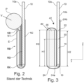
- edge trim RB This usual design of the edge trim RB is the expert, for example, from DE 41 12 256 A1 known and in a schematic representation in the figure 2 shown in a sectional view.
- the lateral edge regions RS of the top cover 10 or the corresponding downward-pointing edges RK are surrounded by an edging band E, which is fixed by sewing using a seam N1 visible from the outside 10a.
- the strip-shaped part of the edging tape E running on the outside 10a of the top cover 10 is simply folded over and guided backwards around the edge RK to the inside 10b of the top cover 10 .
- a cord-shaped profile strand P (keder cord) which is wrapped by a strip-shaped loop of a piping tape KB.
- the loop of the piping strip KB is also sewn to the edge of the top cover 10 via a seam N2.
- a projection V running in the longitudinal direction (x-direction) of the vehicle in the manner of a rain gutter is formed by this cord-shaped profile strand P projecting outwards from the top cloth 10 in the z-direction.
- figure 3 shows the embodiment of the lateral edge region RS/14 of the top cover 10 produced by means of the method according to the invention in a sectional view.
- this lateral edge area 14 runs on both sides of the top cover 10, starting from the front edge area RV in the area of the A pillar to the C pillar in a four-seater convertible. Only a lateral edge region 14 is described below, since the structure of the top cover 10 is mirror-symmetrical with respect to a central axis running in the x-direction.
- the figure shows a section of a lower edge region 14 running in the longitudinal direction and an edge 16 of the top cloth 10 pointing downwards in the z-direction.
- the section of the lateral edge region 14 of the top cloth 10 shown in cross section is designed with a projection 40 running in the longitudinal direction, which forms a channel 42 for water drainage in the longitudinal direction.
- the projection 40 is formed by a strip-shaped, flexible profile 44 running along the edge region 14, which is rectangular in cross section and is enclosed and kept covered by a binding tape 24, as described below.
- the flexible profile 44 has a height H0 and is preferably made of an elastic plastic such as ethylene-propylene-diene rubber (EPDM).
- EPDM ethylene-propylene-diene rubber
- the binding tape 24 comprises a first end area 24a and a second end area 24b and is made of a textile material or a plastic material.
- a strip-shaped part of the edging strip 24 rests directly on the outer side 10a of the top fabric 10, with the edging strip 24 extending upwards in the z direction by means of its first end region 24a, starting from the edge 16 of the top fabric 10 and is fixed at a distance H1, starting from the edge 16, by means of a first seam 30.
- This first seam 30 runs in the longitudinal direction parallel to the marginal edge 16 and is shown only schematically. Starting from the first seam 30, the edging tape continues to run upwards on the outside 10a and is then turned over further outwards and runs downwards in the z-direction and encloses both the flexible profile 44 completely and the edge 16 of the top cover 10.
- the edging strip 24 forms a tunnel-shaped receiving space A for the profile 44, which completely encases it is.
- the binding tape 24 is guided upwards in the z-direction around the edge 16 to the inside 10b and is fixed there at a distance H2 by means of a second seam 32 at its second end region 24b.
- This second seam 32 is also designed as a longitudinal seam parallel to the edge 16 and is arranged in a concealed manner as seen from the outside.
- the second seam 32 is manufactured in such a way that the stitches only penetrate the second end region 24b and the top cover 10 and are executed at the height H2.
- the profile 44 is designed and arranged at its height H0 in such a way that it covers the seam 32 at the height H2 from the visible side and the seam 32 is introduced in the area of the channel 42 .
- a top cloth 10 having an outer side 10a, an inner side 10b and an edge region 14 with an edge 16 is provided.
- an edging tape 24 is provided, which is strip-shaped and includes a first and a second end region 24a, 24b.
- the binding tape 24 is preferably made of a textile material or a plastic.
- a rubber-elastic or flexible, strip-shaped profile is required for the manufacturing process. This is made, for example, from an elastic plastic, for example an EPDM or a foam rubber.
- the edging 24 is applied flush to the edge 16 of the top cloth by means of its first end region 24a, a first strip-shaped region of the edging 24 running upwards in the z direction lying directly on the outside 10a.
- a fixation of the edging strip 24 is then achieved by means of a first seam 30 on the top cover 10 at a height H1.
- the height H1 is measured starting from the edge 16 of the top cover 10, as in the figure 3 is dimensioned.
- the profile 44 fixed on the first strip-shaped area.
- the profile 44 runs upwards in the z-direction, starting from the edge 16, and has a height H0.
- the height H0 is dimensioned in such a way that the profile 44 covers the first seam 30 .
- the profile 44 is fixed, for example, by means of an adhesive tape, which is applied to the profile 44 or the first strip-shaped area 44 .
- an adhesive can also be applied directly to the profile 44 or the strip-shaped area of the edging tape 24 .
- the edge region 14 prefabricated in this way is placed in a folding device.
- the edging strip 24 is then bent over in such a way that the edging strip is simply folded outwards around the profile 44 and in the region of the edge 16 encloses it and is guided upwards on the inside 10b of the top cover 10 in the z-direction. This is in the folded situation in the figure 6 shown.
- the edging strip 24 is fixed to the top cloth 10 in the region of its second end region 24b.
- This is done by means of a second seam 32 at a height H2 on the top cover 10, the second seam 32 being introduced in such a way that only the top cover 10 and the second end region 24b of the edging are sewn using stitches during the sewing process.
- the seam at the height H2 is arranged in such a way that the profile 44 encased with the binding tape 24 covers the second seam 32 .
- the second seam 32 is located above the first seam 30, viewed in the z-direction.
- This arrangement of the second seam 32 is achieved, for example, in such a way that before the sewing process and the production of the second seam 32, the upward-pointing end 44a of the profile 44 enclosed by the binding tape 24 is pressed downwards in the z-direction, so that the outside 10a in the Area of height H2 is exposed for sewing. After the sewing process, the flexible profile 44 expands upwards again in the opposite direction and the second seam 32 is covered by the bordered profile 44 . In this area between the profile 44 and the top cloth 10, a channel 42 running in the longitudinal direction is formed, which is used for water management.
Landscapes
- Engineering & Computer Science (AREA)
- Mechanical Engineering (AREA)
- Sewing Machines And Sewing (AREA)
- Seal Device For Vehicle (AREA)
- Decoration Of Textiles (AREA)
Abstract
Description
- Die Erfindung betrifft ein Verfahren zur Herstellung eines Verdeckbezugs eines Faltverdeck für ein Cabriolet-Fahrzeug sowie Faltverdeck für ein Cabriolet-Fahrzeug.
- Moderne Cabriolet-Fahrzeuge mit einem Faltverdeck und flexiblem Verdeckbezug müssen hohe Ansprüche an Ganzjahrestauglichkeit, Geräusch- und Temperaturisolation sowie an ein optisches Erscheinungsbild erfüllen. Um diesen Anforderungen zu genügen sind derartige Faltverdecke mehrlagig aufgebaut und umfassen einen äußeren Verdeckbezug, in der Regel eine mittlere Polster- oder auch Dämmmatte und einen zum Innenraum weisenden Innenhimmel. Dabei gewährleistet die Polster- und Dämmmatte nicht nur eine akustische sowie thermische Isolation sondern unterstützt auch eine schöne Formgebung des Faltverdecks.
- Soweit eine Polstermatte vorgesehen ist, ist diese als separate Lage ausgeführt und partiell an dem äußeren Verdeckbezugstoff befestigt. Hierdurch wird in der Schließstellung des Faltverdecks eine ausreichende Anlage der Polstermatte am Verdeckbezugstoff erreicht. In der Schließstellung werden der Verdeckbezugstoff sowie die Polstermatte von den Verdeckbauteilen getragen und überspannt den Fahrgastraum. Das verstellbare Faltverdeck erstreckt sich ausgehend von einem auf der Vorderseite angeordneten nicht dargestellten Windschutzscheibenrahmen, der sogenannten A-Säule in einen Heckbereich des Fahrzeugs. Bei einem einem Viersitzer ist dies die C-Säule. Das Faltverdeck ist bezogen auf eine Mittelachse symmetrisch aufgebaut.
- Die Randbereiche des Verdeckbezugs sind in der Regel mit einem Einfassband eingefasst, wobei in den Seitenbereichen des Verdeckbezugs mittels des Einfassbandes auch ein eine Regenrinne bildender Keder mit an den Verdeckbezug angenäht wird. Hierdurch wird sowohl eine Verstärkung des Randbereichs als auch eine Wasserführung erreicht. Nachteilig bei dieser Ausgestaltung der Seitenbereiche mittels des Einfassbandes mit aufgenähter Regenrinne ist die hierfür erforderliche sichtbare Naht auf der Sichtseite des Verdeckbezugstoffes. Diese sichtbare Naht erscheint bei Abweichungen beim Nähvorgang am fertiggestellten Faltverdeck als optisch nicht ansprechend. Des Weiteren verblasst der Nähfaden mit der Lebensdauer und dem Einfluss von Witterungsbedingungen, was ebenfalls als optisch störend empfunden wird.
- Es ist Aufgabe der Erfindung ein Verfahren zur Herstellung eines Verdeckbezugs eines Faltverdecks für ein Cabriolet-Fahrzeug derart weiterzubilden, dass der mit dem Verfahren hergestellte Verdeckbezug hohen Qualitätsanforderungen genügt und gleichzeitig ein hochwertiges, optisch ansprechendes Erscheinungsbild hat.
- Diese Aufgabe wird unter einem ersten Aspekt durch die im Patentanspruch 1 angegebenen Merkmale gelöst.
- Das erfindungsgemäße Faltverdeck basiert im Wesentlichen auf einer Anordnung eines streifenförmigen Einfassbandes und einem gummielastischen oder flexiblen streifenförmigen Profil an einer unteren Randkante des Verdeckbezugs, wobei das Einfassband das Profil taschenförmig umschließt und über eine von der Außenseite her gesehen nicht sichtbare erste und zweite Naht am Verdeckbezug festgelegt ist.
- Das erfindungsgemäße Herstellverfahren zur Herstellung des Verdeckbezugs mit seitlichem Randbereich RS umfasst dabei die folgenden Schritte:
- Bereitstellen eines Verdeckbezugs mit einer Außenseite und einer Innenseite und mit einem Randbereich und einer Randkante
- Bereitstellen eines Einfassbandes, welches streifenförmig ausgeführt und einen ersten und einen zweiten Endbereich umfasst
- Bereitstellen eines gummielastischen oder flexiblen, streifenförmigen Profils
- Anlegen des Einfassbandes mittels seines ersten Endbereichs an die Randkante des Verdeckbezugs, wobei ein erster streifenförmiger Bereich des Einfassbandes in z- Richtung nach oben verlaufend unmittelbar auf der Außenseite anliegt
- Festlegen des Einfassbandes mittels einer ersten Naht am Verdeckbezug in einer Höhe H1 ausgehend von der Randkante
- Fixieren des Profils auf dem ersten streifenförmigen Bereich des Einfassbandes, wobei das Profil ausgehend von der Randkante in z-Richtung nach oben verläuft und eine Höhe H0 ausgehend von der Randkante aufweist, wobei die Höhe H0 derart bemessen ist, dass das Profil die erste Naht in der Höhe H1 überdeckt
- Umbugen des Einfassbandes derart, dass das Einfassband nach außen um das Profil einfach umgeschlagen wird und im Bereich der Randkante diese umschließt und auf der Innenseite des Verdeckbezugs in z-Richtung nach oben geführt wird
- Festlegen des Einfassbandes im Bereich seines zweiten Endbereichs mittels einer zweiten Naht in einer Höhe an dem Verdeckbezug, wobei die zweite Naht derart eingebracht wird, dass ausschließlich der Verdeckbezug und der zweite Endbereich des Einfassbandes beim Nähvorgang vernäht werden.
- Durch das erfindungsgemäße Verfahren kann ein Verdeckbezug eines Faltverdecks für ein Cabriolet-Fahrzeug derart hergestellt werden, dass dieser ein verbessertes optisches Erscheinungsbild durch keine sichtbaren Nähte auf der Sichtseite des Verdeckbezugs hat.
- Es kann eine Regenrinne hergestellt werden, die sich der Faltbewegung des Faltverdecks bei einer Verstellbewegung zwischen der Offen und Schließstellung einfach anpasst und ein sicheres Wassermanagment im seitlichen Randbereich des Faltverdecks gewährleistet. Die Regenrinne wird dabei erfindungsgemäß durch ein elastisches streifenförmiges Einlegeteil realisiert.
- Vorteilhafterweise ist das streifenförmige, elastische Einlegeteil aus einem Kunststoff wie Ethylen-Propylen-Dien-Kautschuk (EPDM) hergestellt. Durch die Verwendung dieses Werkstoffes, kann der Randbereich mit einer wulstartigen in Fahrzeuglängsrichtung verlaufenden Ausprägung hergestellt werden, wobei der Randbereich flexibel ist und sich beim Öffnen und Schließen des Faltverdecks entsprechend anpasst und sich mit dem Verdeckbezug in der Offenstellung des Faltverdecks einfach in Falten legen lässt.
- Weiterbildungen der Erfindung sind in den abhängigen Ansprüchen, der Beschreibung sowie den Zeichnungen angegeben.
- Die x, y, z- Richtung entspricht den Richtungen eines üblichen Fahrzeugkoordinatensystems, bei dem x die Fahrzeuglängsrichtung, y die Querrichtung und z die Hochrichtung bezeichnet.
- Die Erfindung wird nachfolgend beispielhaft unter Bezugnahme auf die beigefügten Zeichnungen beschrieben.
- Es zeigen:
- Fig. 1
- eine Seitenansicht auf ein Faltverdeck bei geschlossenem Verdeck (Schließ-stellung),
- Fig. 2
- einen Querschnitt durch einen seitlichen Randabschnitt des Faltverdecks nach dem Stand der Technik,
- Fig. 3
- einen Querschnitt durch einen seitlichen Randabschnitt des Faltverdecks gemäß der vorliegenden Erfindung,
- Fig. 4
- eine schematische Darstellung der Herstellung des Faltverdecks im seitlichen Randabschnitt in einem ersten Verfahrensschritt,
- Fig. 5
- eine schematische Darstellung der Herstellung des Faltverdecks im seitlichen Randabschnitt in einem zweiten Verfahrensschritt; und
- Fig. 6
- eine schematische Darstellung der Herstellung des Faltverdecks im seitlichen Randabschnitt in einem anschließenden weiteren Verfahrensschritt.
- In
Fig. 1 ist exemplarisch ein Faltverdeck 1 für ein offenes Kraftfahrzeug, ein Cabriolet, dargestellt. Das Cabriolet weist eine Karosserie auf, die in der Darstellung nicht gezeigt wird, auf die oberhalb einer Gürtellinie ein Faltverdeck 1 aufgesetzt ist, dass aus einem einen Fahrgastraum überspannenden Schließstellung in eine nicht gezeigte zusammen gefaltete Ablagestellung/Offenstellung in einen heckseitigen Verdeckkasten bewegt werden kann. Das Faltverdeck weist dabei einen Verdeckbezug 10 aus einem Verdeckbezugstoff auf der sich über einem Verdeckgestänge oder Spriegeln, die in der Zeichnung ebenfalls nicht dargestellt sind, spannt und. Der Verdeckbezug 10 enthält einen Ausschnitt, der zur Aufnahme einer Heckscheibe dient. Der Verdeckbezug 10 hat eine zur Sichtseite weisende Außenseite 10a und eine zum Fahrgastraum weisende Innenseite 10b und ist üblicherweise mehrlagig aus einer Außenlage und einer Innenlage ausgeführt. Dies ist dem Fachmann allgemein bekannt und wird an dieser Stelle nicht näher beschrieben. - Der Verdeckbezug 10 ist besitzt einen umlaufenden Rand R, der an dem Fahrzeug dichtend anliegen muss. Hierbei liegt entweder der Rand R des Verdeckbezugs 10 über Dichtelemente oder ein an dem Verdeckbezug 10 angebundenes Verdeckbauteil über ein Dichtelement an einem Karosseriebauteil an.
- Der Verdeckbezug 10 ist zumindest im vorderen Randbereich RV an der Dachkappe im Bereich der A-Säule angebunden. Über seinen hinteren Randbereich RH ist der Verdeckbezug 10 beispielsweise in geeigneter Weise mit einem Spannbügel verbunden und wird durch den Spannbügel in der Schließposition gespannt. Zwischen dem vorderen Randbereich RV und dem hinteren Randbereich RH erstrecken sich beidseits seitliche Randbereiche RS, die mit einem in Fahrzeuglängsrichtung (x-Richtung) verlaufenden, regenrinnenartigen Vorsprung P ausgeführt sind.
- Diese übliche Ausführung des Randbesatzes RB ist dem Fachmann beispielsweise aus der
DE 41 12 256 A1 bekannt und in einer schematischen Darstellung in derFigur 2 in einer Schnittdarstellung gezeigt. Hierbei werden die seitlichen Randbereiche RS des Verdeckbezugs 10 bzw. die entsprechenden nach unten weisenden Randkanten RK von einem Einfassband E umschlossen, welches durch Nähen mittels einer -von der Außenseite 10a her gesehen- sichtbaren Naht N1 festgelegt ist. Der auf der Außenseite 10a des Verdeckbezugs 10 verlaufende streifenförmige Teil des Einfassbandes E ist dabei einfach umgeschlagen und um die Randkante RK nach hinten auf die Innenseite 10b des Verdeckbezugs 10 geführt. Ferner liegt zwischen dem auf der Außenseite 10a liegenden streifenförmigen Teil des Einfassbandes E und der zugewandten Außenseite 10a des Verdeckbezugs 10 ein schnurförmiger Profilstrang P (Kederschnur) der von einer streifenförmigen Schlaufe eines Kederbandes KB umschlungen ist. Die Schlaufe des Kederbandes KB ist ebenfalls mit dem Rand des Verdeckbezugs 10 über eine Naht N2 vernäht. Durch diesen vom Verdeckbezug 10 in z-Richtung nach außen abstehenden schnurförmigen Profilstrang P ist ein regenrinnenartiger in Fahrzeuglängsrichtung (x-Richtung) verlaufender Vorsprung V gebildet. -
Figur 3 zeigt die mittels des erfindungsgemäßen Verfahrens hergestellte Ausführung des seitlichen Randbereichs RS/14 des Verdeckbezugs 10 in einer Schnittansicht. Wie bereits beschrieben verläuft dieser seitliche Randbereich 14 jeweils beidseits des Verdeckbezugs 10 ausgehend von dem vorderen Randbereich RV im Bereich der A-Säule bis zu der C-Säule bei einem Viersitzer Cabriolet. Nachfolgend wird nur ein seitlicher Randbereich 14 beschrieben, da der Aufbau des Verdeckbezugs 10 bezogen auf eine in x-Richtung verlaufende Mittelachse spiegelsymmetrisch aufgebaut ist. Die Figur zeigt dabei einen Ausschnitt eines unteren in Längsrichtung verlaufenden Randbereich 14 und eine in z-Richtung nach unten weisende Randkante 16 des Verdeckbezugs 10. - Der im Querschnitt dargestellte Ausschnitt des seitlichen Randbereichs 14 des Verdeckbezugs 10 ist mit einem in Längsrichtung verlaufenden Vorsprung 40 ausgeführt, der eine Rinne 42 zum Wasserablauf in Längsrichtung ausbildet.
- Der Vorsprung 40 wird durch ein streifenförmig am Randbereich 14 verlaufendes weichelastisches Profil 44 gebildet, welches im Querschnitt rechteckig ausgebildet ist und von einem Einfassband 24, wie nachfolgend beschrieben, umschlossen, abgedeckt gehalten wird. Das weichelastische Profil 44 besitzt eine Höhe H0 und ist vorzugsweise aus einem elastischen Kunststoff wie einem Ethylen-Propylen-Dien-Kautschuk (EPDM) ausgeführt. Das Profil 44 schließt mit seiner in Hochrichtung nach unten weisenden Unterkante 44a im Wesentlichen bündig mit der Randkante 16 ab.
- Das Einfassband 24 umfasst einen ersten Endbereich 24a und einen zweiten Endbereich 24b und ist aus einem textilen Material oder einem Kunststoffmaterial.
- Wie es aus der Zeichnung der
Figur 3 bzw. 6 zu erkennen ist, liegt ein streifenförmiger Teil des Einfassbandes 24 unmittelbar auf der Außenseite 10a des Verdeckbezugs 10 an, wobei sich das Einfassband 24 mittels seines ersten Endbereichs 24a ausgehend von der Randkante 16 des Verdeckbezugs 10 in z- Richtung nach oben erstreckt und in einem Abstand H1 ausgehend von der Randkante 16 mittels einer ersten Naht 30 festgelegt ist. Dies erste Naht 30 verläuft in Längsrichtung parallel zur Randkante 16 und ist nur schematisch angezeigt. Ausgehend von der ersten Naht 30 verläuft das Einfassband weiter auf der Außenseite 10a nach oben und ist dann im weiteren Verlauf nach außen hin umgeschlagen und verläuft in z- Richtung nach unten und umschließt dabei sowohl das weichelastische Profil 44 vollständig als auch die Randkante 16 des Verdeckbezugs 10. Wie es aus den Zeichnungen zu erkennen ist, bildet das Einfassband 24 einen tunnelförmigen Aufnahmeraum A für das Profil 44, welches vollständig ummantelt ist. Das Einfassband 24 ist ausgehend von der Außenseite um die Randkante 16 auf die Innenseite 10b in z- Richtung nach oben geführt und dort in einem Abstand H2 mittels einer zweiten Naht 32 an seinem zweiten Endbereich 24b festgelegt. Diese zweite Naht 32 ist ebenfalls als Längsnaht parallel zur Randkante 16 ausgebildet und von der Außenseite gesehen verdeckt angeordnet. Die zweite Naht 32 ist derart gefertigt, dass die Stiche ausschließlich den zweiten Endbereich 24b und den Verdeckbezug 10 durchdringen und in der Höhe H2 ausgeführt sind. Das Profil 44 ist in seiner Höhe H0 derart ausgeführt und angeordnet, dass es die Naht 32 in der Höhe H2 von der Sichtseite her verdeckt und die Naht 32 im Bereich der Rinne 42 eingebracht ist. - Bei dem Verfahren zur Herstellung des Verdeckbezugs 10 mit seitlichem Randbereich 14 sind folgende Schritte vorgesehen:
Zunächst wird ein Verdeckbezugs 10, der eine Außenseite 10a, eine Innenseite 10b und einen Randbereich 14 mit einer Randkante 16 aufweist bereitgestellt. Des Weiteren wird ein Einfassband 24 bereitgestellt, welches streifenförmig ausgeführt ist und einen ersten und einen zweiten Endbereich 24a, 24b umfasst. Das Einfassband 24 ist vorzugsweise aus einem textilen Material oder einem Kunststoff. Weiterhin wird für das Herstellverfahren ein gummielastischen oder flexiblen, streifenförmigen Profil benötigt. Dieses ist beispielsweise aus einem elastischen Kunststoff z.B. einem EPDM oder einem Moosgummi. - In einem ersten Verfahrensschritt, der in der
Figur 4 dargestellt ist, wird das Einfassband 24 mittels seines ersten Endbereichs 24a bündig an die Randkante 16 des Verdeckbezugs angelegt, wobei ein erster streifenförmiger Bereich des Einfassbandes 24 in z- Richtung nach oben verlaufend unmittelbar auf der Außenseite 10a anliegt. Eine Fixierung des Einfassbandes 24 wird dann mittels einer ersten Naht 30 am Verdeckbezug 10 in einer Höhe H1 erreicht. Die Höhe H1 bemisst sich ausgehend von der Randkante 16 des Verdeckbezugs 10, wie es in derFigur 3 bemaßt ist. - Nachdem das Einfassband auf der Außenseite des Verdeckbezugs 10 fixiert angeordnet ist, wird in einem in der
Figur 5 dargestellten nachfolgenden Verfahrensschritt das Profil 44 auf dem ersten streifenförmigen Bereich festgelegt. Hierbei verläuft das Profil 44 ausgehend von der Randkante 16 in z-Richtung nach oben und weist eine Höhe H0 auf. Die Höhe H0 ist derart bemessen, dass das Profil 44 die erste Naht 30 überdeckt. Das Fixieren des Profils 44 erfolgt beispielsweise mittels eines Klebebandes, welches auf das Profil 44 oder den ersten streifenförmigen Bereich 44 appliziert wird. In einer alternativen Variante kann auch unmittelbar auf das Profil 44 oder den streifenförmigen Bereich des Einfassbandes 24 ein Klebstoff appliziert werden. - Nach dem Festlegen des Profils 44 wird der derart vorkonfektionierte Randbereich 14 in eine Umbugvorrichtung eingelegt. Es erfolgt dann ein Umbugen des Einfassbandes 24 derart, dass das Einfassband nach außen um das Profil 44 einfach umgeschlagen wird und im Bereich der Randkante 16 diese umschließt und auf der Innenseite 10b des Verdeckbezugs 10 in z-Richtung nach oben geführt wird. Dies ist in der umgebugten Situation in der
Figur 6 dargestellt. - Abschließend wird nun das Einfassband 24 im Bereich seines zweiten Endbereichs 24b an dem Verdeckbezug 10 festgelegt. Dies erfolgt mittels einer zweiten Naht 32 in einer Höhe H2 an dem Verdeckbezug 10, wobei die zweite Naht 32 derart eingebracht wird, dass ausschließlich der Verdeckbezug 10 und der zweite Endbereich 24b des Einfassbandes mittels Stichen beim Nähvorgang vernäht werden. Die Naht in der Höhe H2 ist dabei derart angeordnet, dass das mit dem Einfassband 24 ummantelte Profil 44 die zweite Naht 32 überdeckt. Wie es aus der Darstellung der
Figuren 3 und6 zu erkennen ist, liegt die zweite Naht 32 in z- Richtung gesehen über der ersten Naht 30. - Diese Anordnung der zweiten Naht 32 wird beispielsweise derart erreicht, dass vor dem Nähvorgang und Herstellen der zweiten Naht 32 das nach oben weisende Ende 44a des mit dem Einfassband 24 umschlossenen Profils 44 in z-Richtung nach unten gedrückt wird, so dass die Außenseite 10a im Bereich der Höhe H2 für den Nähvorgang freiliegend ist. Nach dem Nähvorgang dehnt sich das flexible Profil 44 wieder in die entgegengesetzte Richtung nach oben aus und die zweite Naht 32 ist mittels des eingefassten Profils 44 verdeckt. In diesem Bereich zwischen Profil 44 und Verdeckbezug 10 bildet sich dabei eine in Längsrichtung verlaufende Rinne 42 die dem Wassermanagment dient.
-
- 1
- Faltverdeck
- 10
- Verdeckbezug
- 10a
- Außenseite
- 10b
- Innenseite
- 14
- Randbereich
- 16
- Randkante
- 24
- Einfassband
- 24a
- erster Endbereich
- 24b
- zweiter Endbereich
- 30
- erste Naht
- 32
- zweite Naht
- 40
- Vorsprung
- 42
- Rinne
- 44
- Profil
- R
- Rand
- RV
- vorderer Randbereich
- RH
- hinterer Randbereich
- RS
- seitlicher Randbereich
Claims (7)
- Verfahren zur Herstellung eines Verdeckbezugs (10) eines Faltverdeck (1) für ein Cabriolet-Fahrzeug, wobei der Verdeckbezug (10) eine Außenseite (10a) und eine Innenseite (10b) umfasst und weiterhin zumindest einen seitlichen Randbereiche (14) mit einer Randkante (16) aufweist, wobei der seitliche Randbereich (14) im Bereich der Randkante (16) mit einem zur Außenseite (10a) weisenden Vorsprung (V), welcher eine in Längsrichtung verlaufende Rinne (42) bildet, ausgeführt ist, mit den Schritten:a. Bereitstellen eines Verdeckbezugs (10) mit einer Außenseite (10a) und einer Innenseite (10b) und mit einem Randbereich (14) und einer Randkante (16)b. Bereitstellen eines Einfassbandes (24), welches streifenförmig ausgeführt und einen ersten und einen zweiten Endbereich (24a, 24b) umfasstc. Bereitstellen eines gummielastischen oder flexiblen, streifenförmigen Profils (44)d. Anlegen des Einfassbandes (24) mittels seines ersten Endbereichs (24a) an die Randkante (16) des Verdeckbezugs (10), wobei das Einfassbandes (24) in z-Richtung nach oben verlaufend unmittelbar auf der Außenseite (10a) anliegt und der zweite Endbereich (24b) nach oben weisend ausgerichtet iste. Festlegen des Einfassbandes (24) mittels einer ersten Naht (30) am Verdeckbezug (10) in einer Höhe H1 ausgehend von der Randkante (16)f. Fixieren des Profils (44) auf dem Einfassband (24), wobei das Profil (44) ausgehend von der Randkante (16) in z-Richtung nach oben verläuft und eine Höhe H0 ausgehend von der Randkante (16) aufweist, wobei die Höhe H0 derart bemessen ist, dass das Profil (44) die erste Naht (30) in der Höhe H1 überdecktg. Umschlagen des Einfassbandes (24) derart, dass das Einfassband (24) nach außen um eine in z-Richtung nach oben weisende Seitenkante (44a) des Profils (44) einfach umgeschlagen wird, in z- Richtung auf einer Außenseite nach unten geführt wird und im weiteren Verlauf den Bereich der Randkante (16) umschließt und auf der Innenseite (10b) des Verdeckbezugs (10) in z-Richtung nach oben geführt wirdh. Festlegen des Einfassbandes (24) im Bereich seines zweiten Endbereichs (24b) mittels einer zweiten Naht (32) in einer Höhe H2 an dem Verdeckbezug (10), wobei die zweite Naht (32) derart eingebracht wird, dass ausschließlich der Verdeckbezug (10) und der zweite Endbereich (24b) des Einfassbandes (24) beim Nähvorgang vernäht werden und die zweite Naht (32) mittels des eingefassten Profils (44) verdeckt angeordnet ist.
- Verfahren zur Herstellung eines Verdeckbezugs (10) nach Anspruch 1, dadurch gekennzeichnet, dass das Fixieren des Profils (44) in Schritt f mittels eines Klebebandes erfolgt, welches auf das Profil (44) oder den ersten streifenförmigen Bereich des Einfassbandes (24) appliziert wird.
- Verfahren zur Herstellung eines Verdeckbezugs (10) nach Anspruch 1, dadurch gekennzeichnet, dass das Fixieren des Profils (44) in Schritt f durch ein unmittelbares Verkleben erfolgt, wobei ein Klebstoff auf das Profil (44) oder den streifenförmigen Bereich des Einfassbandes (24) appliziert wird.
- Verfahren zur Herstellung eines Verdeckbezugs (10) nach einem der vorangehenden Ansprüche, dadurch gekennzeichnet, dass das Umschlagen des Einfassbandes (24) in Schritt g in einer Umbugvorrichtung erfolgt.
- Verfahren zur Herstellung eines Verdeckbezugs (10) nach einem der vorangehenden Ansprüche, dadurch gekennzeichnet, dass die zweite Naht (32) in einer Höhe H2 in dem Schritt h derart eingebracht wird, dass vor dem Nähvorgang und Herstellen der zweiten Naht (32) das nach oben weisende Ende (44a) des mit dem Einfassband (24) umschlossenen/eingefassten Profils (44) in z-Richtung nach unten gedrückt wird, so dass die Außenseite (10a) im Bereich der Höhe H2 für den Nähvorgang freiliegend ist.
- Verfahren zur Herstellung eines Verdeckbezugs (10) nach einem der vorangehenden Ansprüche, dadurch gekennzeichnet, dass als Profil (44) ein elastischer Kunststoff z.B. ein EPDM oder ein Moosgummi verwendet wird.
- Verdeckbezug (10) für ein Faltverdecks, wobei der Verdeckbezug (10) nach einem der vorangehenden Ansprüche 1-6 hergestellt ist.
Applications Claiming Priority (1)
| Application Number | Priority Date | Filing Date | Title |
|---|---|---|---|
| DE102021213223.5A DE102021213223B4 (de) | 2021-11-24 | 2021-11-24 | Verfahren zur Herstellung eines Verdeckbezugs eines Faltverdecks für ein Cabriolet-Fahrzeug sowie Faltverdeck für ein Cabriolet-Fahrzeug |
Publications (2)
| Publication Number | Publication Date |
|---|---|
| EP4186726A1 true EP4186726A1 (de) | 2023-05-31 |
| EP4186726B1 EP4186726B1 (de) | 2024-06-12 |
Family
ID=84246048
Family Applications (1)
| Application Number | Title | Priority Date | Filing Date |
|---|---|---|---|
| EP22205350.6A Active EP4186726B1 (de) | 2021-11-24 | 2022-11-03 | Verfahren zur herstellung eines verdeckbezugs eines faltverdecks für ein cabriolet-fahrzeug sowie faltverdeck für ein cabriolet-fahrzeug |
Country Status (2)
| Country | Link |
|---|---|
| EP (1) | EP4186726B1 (de) |
| DE (1) | DE102021213223B4 (de) |
Citations (5)
| Publication number | Priority date | Publication date | Assignee | Title |
|---|---|---|---|---|
| DE4112256A1 (de) | 1991-04-15 | 1992-10-22 | Parat Werk Schoenenbach Gmbh | Klapp- bzw. faltverdeck fuer fahrzeuge wie cabriolets o. dgl. |
| DE29819187U1 (de) * | 1998-10-28 | 1999-08-12 | Wilhelm Karmann GmbH, 49084 Osnabrück | Kraftfahrzeug mit einem faltbaren Verdeck |
| US6189950B1 (en) * | 1997-10-29 | 2001-02-20 | Nishikawa Rubber Co., Ltd. | Sealing structure for a convertible |
| EP1103402A2 (de) * | 1999-11-26 | 2001-05-30 | PARAT Automotive, Schönenbach GmbH + Co. KG | Cabriolet-Verdeck |
| JP2005349930A (ja) * | 2004-06-10 | 2005-12-22 | Toyo Seat Co Ltd | 車両用幌の雨垂れ防止構造 |
Family Cites Families (2)
| Publication number | Priority date | Publication date | Assignee | Title |
|---|---|---|---|---|
| US2765192A (en) | 1953-04-16 | 1956-10-02 | Blake George | Replaceable cover for convertible automobile top |
| DE102014110646A1 (de) | 2014-07-29 | 2016-02-04 | Dr. Ing. H.C. F. Porsche Aktiengesellschaft | Fahrzeugverdeck |
-
2021
- 2021-11-24 DE DE102021213223.5A patent/DE102021213223B4/de active Active
-
2022
- 2022-11-03 EP EP22205350.6A patent/EP4186726B1/de active Active
Patent Citations (5)
| Publication number | Priority date | Publication date | Assignee | Title |
|---|---|---|---|---|
| DE4112256A1 (de) | 1991-04-15 | 1992-10-22 | Parat Werk Schoenenbach Gmbh | Klapp- bzw. faltverdeck fuer fahrzeuge wie cabriolets o. dgl. |
| US6189950B1 (en) * | 1997-10-29 | 2001-02-20 | Nishikawa Rubber Co., Ltd. | Sealing structure for a convertible |
| DE29819187U1 (de) * | 1998-10-28 | 1999-08-12 | Wilhelm Karmann GmbH, 49084 Osnabrück | Kraftfahrzeug mit einem faltbaren Verdeck |
| EP1103402A2 (de) * | 1999-11-26 | 2001-05-30 | PARAT Automotive, Schönenbach GmbH + Co. KG | Cabriolet-Verdeck |
| JP2005349930A (ja) * | 2004-06-10 | 2005-12-22 | Toyo Seat Co Ltd | 車両用幌の雨垂れ防止構造 |
Also Published As
| Publication number | Publication date |
|---|---|
| DE102021213223B4 (de) | 2023-06-07 |
| DE102021213223A1 (de) | 2023-05-25 |
| EP4186726B1 (de) | 2024-06-12 |
Similar Documents
| Publication | Publication Date | Title |
|---|---|---|
| DE2655990C2 (de) | ||
| DE10007575A1 (de) | Klapp bzw. Faltverdeck für Kraftfahrzeuge mit einem äußeren Verdeckbezug und mindestens einer an diesem angeordeten Scheibe | |
| EP1092576B1 (de) | Verdeck für Fahrzeuge, insbes. Klapp- oder Faltverdeck | |
| DE10240759C5 (de) | Verdeck für ein Cabriolet-Fahrzeug | |
| DE102016115505A1 (de) | Faltverdeck mit Flächenspriegeln | |
| DE8333168U1 (de) | Cabriolet-verdeckattrappe | |
| DE102021213223B4 (de) | Verfahren zur Herstellung eines Verdeckbezugs eines Faltverdecks für ein Cabriolet-Fahrzeug sowie Faltverdeck für ein Cabriolet-Fahrzeug | |
| DE19910950C1 (de) | Schiebehimmel für ein Fahrzeugdach | |
| DE1530674A1 (de) | Kabriolett-Winterverdeck | |
| EP1092575B1 (de) | Klapp-bzw. Faltverdeck für Fahrzeuge wie Cabriolets od. dgl. | |
| DE10214235A1 (de) | Formteil und Verfahren zu dessen Herstellung | |
| WO2005095138A1 (de) | Verdeck eines cabriolet-kraftfahrzeuges | |
| DE102020208589B4 (de) | Faltverdeck für ein Cabriolet-Fahrzeug | |
| EP3974218B1 (de) | Faltverdeck für ein cabriolet-fahrzeug mit beweglicher heckscheibe | |
| DE102009035043B4 (de) | Dachstruktur für ein Cabrioletfahrzeug | |
| EP1384610B2 (de) | Dachkonstruktion für Fahrzeuge | |
| DE102006044234B4 (de) | Cabriolet-Verdeckbezug | |
| EP3967532B1 (de) | Faltverdeck für ein cabriolet-fahrzeug | |
| DE10056894B4 (de) | Cabriolet-Fahrzeug | |
| EP1040949A2 (de) | Klapp- bzw. Faltverdeck für Kraftfahrzeuge mit einem äusseren Verdeckbezug und mindestens einer an diesem angeordneten Scheibe | |
| DE4234811A1 (de) | Cabriolet-Verdeck | |
| DE102011014694B4 (de) | Faltbares Verdeck für ein Cabriolet-Fahrzeug, insbesondere für ein zumindest 4-sitziges Cabriolet-Fahrzeug | |
| DE102011014693B4 (de) | Faltbares Verdeck für ein Cabriolet-Fahrzeug, insbesondere für ein zumindest 4-sitziges Cabriolet-Fahrzeug | |
| DE10156350A1 (de) | Kraftwagen mit einem Dachmodul | |
| DE29918234U1 (de) | Verdeck für Fahrzeuge, insbesondere Klapp- oder Faltverdeck |
Legal Events
| Date | Code | Title | Description |
|---|---|---|---|
| PUAI | Public reference made under article 153(3) epc to a published international application that has entered the european phase |
Free format text: ORIGINAL CODE: 0009012 |
|
| STAA | Information on the status of an ep patent application or granted ep patent |
Free format text: STATUS: THE APPLICATION HAS BEEN PUBLISHED |
|
| AK | Designated contracting states |
Kind code of ref document: A1 Designated state(s): AL AT BE BG CH CY CZ DE DK EE ES FI FR GB GR HR HU IE IS IT LI LT LU LV MC ME MK MT NL NO PL PT RO RS SE SI SK SM TR |
|
| STAA | Information on the status of an ep patent application or granted ep patent |
Free format text: STATUS: REQUEST FOR EXAMINATION WAS MADE |
|
| 17P | Request for examination filed |
Effective date: 20230718 |
|
| RBV | Designated contracting states (corrected) |
Designated state(s): AL AT BE BG CH CY CZ DE DK EE ES FI FR GB GR HR HU IE IS IT LI LT LU LV MC ME MK MT NL NO PL PT RO RS SE SI SK SM TR |
|
| GRAP | Despatch of communication of intention to grant a patent |
Free format text: ORIGINAL CODE: EPIDOSNIGR1 |
|
| STAA | Information on the status of an ep patent application or granted ep patent |
Free format text: STATUS: GRANT OF PATENT IS INTENDED |
|
| INTG | Intention to grant announced |
Effective date: 20240116 |
|
| GRAS | Grant fee paid |
Free format text: ORIGINAL CODE: EPIDOSNIGR3 |
|
| GRAA | (expected) grant |
Free format text: ORIGINAL CODE: 0009210 |
|
| STAA | Information on the status of an ep patent application or granted ep patent |
Free format text: STATUS: THE PATENT HAS BEEN GRANTED |
|
| AK | Designated contracting states |
Kind code of ref document: B1 Designated state(s): AL AT BE BG CH CY CZ DE DK EE ES FI FR GB GR HR HU IE IS IT LI LT LU LV MC ME MK MT NL NO PL PT RO RS SE SI SK SM TR |
|
| REG | Reference to a national code |
Ref country code: GB Ref legal event code: FG4D Free format text: NOT ENGLISH |
|
| REG | Reference to a national code |
Ref country code: CH Ref legal event code: EP |
|
| REG | Reference to a national code |
Ref country code: DE Ref legal event code: R096 Ref document number: 502022001041 Country of ref document: DE |
|
| P01 | Opt-out of the competence of the unified patent court (upc) registered |
Effective date: 20240527 |
|
| REG | Reference to a national code |
Ref country code: IE Ref legal event code: FG4D Free format text: LANGUAGE OF EP DOCUMENT: GERMAN |
|
| PG25 | Lapsed in a contracting state [announced via postgrant information from national office to epo] |
Ref country code: BG Free format text: LAPSE BECAUSE OF FAILURE TO SUBMIT A TRANSLATION OF THE DESCRIPTION OR TO PAY THE FEE WITHIN THE PRESCRIBED TIME-LIMIT Effective date: 20240612 |
|
| PG25 | Lapsed in a contracting state [announced via postgrant information from national office to epo] |
Ref country code: FI Free format text: LAPSE BECAUSE OF FAILURE TO SUBMIT A TRANSLATION OF THE DESCRIPTION OR TO PAY THE FEE WITHIN THE PRESCRIBED TIME-LIMIT Effective date: 20240612 Ref country code: HR Free format text: LAPSE BECAUSE OF FAILURE TO SUBMIT A TRANSLATION OF THE DESCRIPTION OR TO PAY THE FEE WITHIN THE PRESCRIBED TIME-LIMIT Effective date: 20240612 |
|
| REG | Reference to a national code |
Ref country code: LT Ref legal event code: MG9D |
|
| PG25 | Lapsed in a contracting state [announced via postgrant information from national office to epo] |
Ref country code: GR Free format text: LAPSE BECAUSE OF FAILURE TO SUBMIT A TRANSLATION OF THE DESCRIPTION OR TO PAY THE FEE WITHIN THE PRESCRIBED TIME-LIMIT Effective date: 20240913 |
|
| REG | Reference to a national code |
Ref country code: NL Ref legal event code: MP Effective date: 20240612 |
|
| PG25 | Lapsed in a contracting state [announced via postgrant information from national office to epo] |
Ref country code: ES Free format text: LAPSE BECAUSE OF FAILURE TO SUBMIT A TRANSLATION OF THE DESCRIPTION OR TO PAY THE FEE WITHIN THE PRESCRIBED TIME-LIMIT Effective date: 20240612 |
|
| PG25 | Lapsed in a contracting state [announced via postgrant information from national office to epo] |
Ref country code: LV Free format text: LAPSE BECAUSE OF FAILURE TO SUBMIT A TRANSLATION OF THE DESCRIPTION OR TO PAY THE FEE WITHIN THE PRESCRIBED TIME-LIMIT Effective date: 20240612 |
|
| PG25 | Lapsed in a contracting state [announced via postgrant information from national office to epo] |
Ref country code: NO Free format text: LAPSE BECAUSE OF FAILURE TO SUBMIT A TRANSLATION OF THE DESCRIPTION OR TO PAY THE FEE WITHIN THE PRESCRIBED TIME-LIMIT Effective date: 20240912 Ref country code: LV Free format text: LAPSE BECAUSE OF FAILURE TO SUBMIT A TRANSLATION OF THE DESCRIPTION OR TO PAY THE FEE WITHIN THE PRESCRIBED TIME-LIMIT Effective date: 20240612 Ref country code: HR Free format text: LAPSE BECAUSE OF FAILURE TO SUBMIT A TRANSLATION OF THE DESCRIPTION OR TO PAY THE FEE WITHIN THE PRESCRIBED TIME-LIMIT Effective date: 20240612 Ref country code: GR Free format text: LAPSE BECAUSE OF FAILURE TO SUBMIT A TRANSLATION OF THE DESCRIPTION OR TO PAY THE FEE WITHIN THE PRESCRIBED TIME-LIMIT Effective date: 20240913 Ref country code: FI Free format text: LAPSE BECAUSE OF FAILURE TO SUBMIT A TRANSLATION OF THE DESCRIPTION OR TO PAY THE FEE WITHIN THE PRESCRIBED TIME-LIMIT Effective date: 20240612 Ref country code: ES Free format text: LAPSE BECAUSE OF FAILURE TO SUBMIT A TRANSLATION OF THE DESCRIPTION OR TO PAY THE FEE WITHIN THE PRESCRIBED TIME-LIMIT Effective date: 20240612 Ref country code: BG Free format text: LAPSE BECAUSE OF FAILURE TO SUBMIT A TRANSLATION OF THE DESCRIPTION OR TO PAY THE FEE WITHIN THE PRESCRIBED TIME-LIMIT Effective date: 20240612 Ref country code: RS Free format text: LAPSE BECAUSE OF FAILURE TO SUBMIT A TRANSLATION OF THE DESCRIPTION OR TO PAY THE FEE WITHIN THE PRESCRIBED TIME-LIMIT Effective date: 20240912 |
|
| PG25 | Lapsed in a contracting state [announced via postgrant information from national office to epo] |
Ref country code: NL Free format text: LAPSE BECAUSE OF FAILURE TO SUBMIT A TRANSLATION OF THE DESCRIPTION OR TO PAY THE FEE WITHIN THE PRESCRIBED TIME-LIMIT Effective date: 20240612 |
|
| PG25 | Lapsed in a contracting state [announced via postgrant information from national office to epo] |
Ref country code: NL Free format text: LAPSE BECAUSE OF FAILURE TO SUBMIT A TRANSLATION OF THE DESCRIPTION OR TO PAY THE FEE WITHIN THE PRESCRIBED TIME-LIMIT Effective date: 20240612 |
|
| PG25 | Lapsed in a contracting state [announced via postgrant information from national office to epo] |
Ref country code: PT Free format text: LAPSE BECAUSE OF FAILURE TO SUBMIT A TRANSLATION OF THE DESCRIPTION OR TO PAY THE FEE WITHIN THE PRESCRIBED TIME-LIMIT Effective date: 20241014 |
|
| PG25 | Lapsed in a contracting state [announced via postgrant information from national office to epo] |
Ref country code: PT Free format text: LAPSE BECAUSE OF FAILURE TO SUBMIT A TRANSLATION OF THE DESCRIPTION OR TO PAY THE FEE WITHIN THE PRESCRIBED TIME-LIMIT Effective date: 20241014 |
|
| PG25 | Lapsed in a contracting state [announced via postgrant information from national office to epo] |
Ref country code: PL Free format text: LAPSE BECAUSE OF FAILURE TO SUBMIT A TRANSLATION OF THE DESCRIPTION OR TO PAY THE FEE WITHIN THE PRESCRIBED TIME-LIMIT Effective date: 20240612 |
|
| PG25 | Lapsed in a contracting state [announced via postgrant information from national office to epo] |
Ref country code: EE Free format text: LAPSE BECAUSE OF FAILURE TO SUBMIT A TRANSLATION OF THE DESCRIPTION OR TO PAY THE FEE WITHIN THE PRESCRIBED TIME-LIMIT Effective date: 20240612 |
|
| PG25 | Lapsed in a contracting state [announced via postgrant information from national office to epo] |
Ref country code: IS Free format text: LAPSE BECAUSE OF FAILURE TO SUBMIT A TRANSLATION OF THE DESCRIPTION OR TO PAY THE FEE WITHIN THE PRESCRIBED TIME-LIMIT Effective date: 20241012 |
|
| PG25 | Lapsed in a contracting state [announced via postgrant information from national office to epo] |
Ref country code: CZ Free format text: LAPSE BECAUSE OF FAILURE TO SUBMIT A TRANSLATION OF THE DESCRIPTION OR TO PAY THE FEE WITHIN THE PRESCRIBED TIME-LIMIT Effective date: 20240612 |
|
| PG25 | Lapsed in a contracting state [announced via postgrant information from national office to epo] |
Ref country code: RO Free format text: LAPSE BECAUSE OF FAILURE TO SUBMIT A TRANSLATION OF THE DESCRIPTION OR TO PAY THE FEE WITHIN THE PRESCRIBED TIME-LIMIT Effective date: 20240612 Ref country code: SK Free format text: LAPSE BECAUSE OF FAILURE TO SUBMIT A TRANSLATION OF THE DESCRIPTION OR TO PAY THE FEE WITHIN THE PRESCRIBED TIME-LIMIT Effective date: 20240612 |
|
| PG25 | Lapsed in a contracting state [announced via postgrant information from national office to epo] |
Ref country code: SM Free format text: LAPSE BECAUSE OF FAILURE TO SUBMIT A TRANSLATION OF THE DESCRIPTION OR TO PAY THE FEE WITHIN THE PRESCRIBED TIME-LIMIT Effective date: 20240612 |
|
| PG25 | Lapsed in a contracting state [announced via postgrant information from national office to epo] |
Ref country code: SM Free format text: LAPSE BECAUSE OF FAILURE TO SUBMIT A TRANSLATION OF THE DESCRIPTION OR TO PAY THE FEE WITHIN THE PRESCRIBED TIME-LIMIT Effective date: 20240612 Ref country code: SK Free format text: LAPSE BECAUSE OF FAILURE TO SUBMIT A TRANSLATION OF THE DESCRIPTION OR TO PAY THE FEE WITHIN THE PRESCRIBED TIME-LIMIT Effective date: 20240612 Ref country code: RO Free format text: LAPSE BECAUSE OF FAILURE TO SUBMIT A TRANSLATION OF THE DESCRIPTION OR TO PAY THE FEE WITHIN THE PRESCRIBED TIME-LIMIT Effective date: 20240612 Ref country code: PL Free format text: LAPSE BECAUSE OF FAILURE TO SUBMIT A TRANSLATION OF THE DESCRIPTION OR TO PAY THE FEE WITHIN THE PRESCRIBED TIME-LIMIT Effective date: 20240612 Ref country code: IS Free format text: LAPSE BECAUSE OF FAILURE TO SUBMIT A TRANSLATION OF THE DESCRIPTION OR TO PAY THE FEE WITHIN THE PRESCRIBED TIME-LIMIT Effective date: 20241012 Ref country code: EE Free format text: LAPSE BECAUSE OF FAILURE TO SUBMIT A TRANSLATION OF THE DESCRIPTION OR TO PAY THE FEE WITHIN THE PRESCRIBED TIME-LIMIT Effective date: 20240612 Ref country code: CZ Free format text: LAPSE BECAUSE OF FAILURE TO SUBMIT A TRANSLATION OF THE DESCRIPTION OR TO PAY THE FEE WITHIN THE PRESCRIBED TIME-LIMIT Effective date: 20240612 |
|
| PG25 | Lapsed in a contracting state [announced via postgrant information from national office to epo] |
Ref country code: IT Free format text: LAPSE BECAUSE OF FAILURE TO SUBMIT A TRANSLATION OF THE DESCRIPTION OR TO PAY THE FEE WITHIN THE PRESCRIBED TIME-LIMIT Effective date: 20240612 |
|
| REG | Reference to a national code |
Ref country code: DE Ref legal event code: R097 Ref document number: 502022001041 Country of ref document: DE |
|
| PG25 | Lapsed in a contracting state [announced via postgrant information from national office to epo] |
Ref country code: DK Free format text: LAPSE BECAUSE OF FAILURE TO SUBMIT A TRANSLATION OF THE DESCRIPTION OR TO PAY THE FEE WITHIN THE PRESCRIBED TIME-LIMIT Effective date: 20240612 |
|
| PLBE | No opposition filed within time limit |
Free format text: ORIGINAL CODE: 0009261 |
|
| STAA | Information on the status of an ep patent application or granted ep patent |
Free format text: STATUS: NO OPPOSITION FILED WITHIN TIME LIMIT |
|
| REG | Reference to a national code |
Ref country code: DE Ref legal event code: R082 Ref document number: 502022001041 Country of ref document: DE Representative=s name: EULER, MATTHIAS, DR., DE |
|
| 26N | No opposition filed |
Effective date: 20250313 |
|
| PG25 | Lapsed in a contracting state [announced via postgrant information from national office to epo] |
Ref country code: MC Free format text: LAPSE BECAUSE OF FAILURE TO SUBMIT A TRANSLATION OF THE DESCRIPTION OR TO PAY THE FEE WITHIN THE PRESCRIBED TIME-LIMIT Effective date: 20240612 |
|
| PG25 | Lapsed in a contracting state [announced via postgrant information from national office to epo] |
Ref country code: LU Free format text: LAPSE BECAUSE OF NON-PAYMENT OF DUE FEES Effective date: 20241103 |
|
| REG | Reference to a national code |
Ref country code: BE Ref legal event code: MM Effective date: 20241130 |
|
| PG25 | Lapsed in a contracting state [announced via postgrant information from national office to epo] |
Ref country code: SE Free format text: LAPSE BECAUSE OF FAILURE TO SUBMIT A TRANSLATION OF THE DESCRIPTION OR TO PAY THE FEE WITHIN THE PRESCRIBED TIME-LIMIT Effective date: 20240612 |
|
| PG25 | Lapsed in a contracting state [announced via postgrant information from national office to epo] |
Ref country code: BE Free format text: LAPSE BECAUSE OF NON-PAYMENT OF DUE FEES Effective date: 20241130 |
|
| PG25 | Lapsed in a contracting state [announced via postgrant information from national office to epo] |
Ref country code: IE Free format text: LAPSE BECAUSE OF NON-PAYMENT OF DUE FEES Effective date: 20241103 |
|
| PGFP | Annual fee paid to national office [announced via postgrant information from national office to epo] |
Ref country code: DE Payment date: 20251119 Year of fee payment: 4 |
|
| PGFP | Annual fee paid to national office [announced via postgrant information from national office to epo] |
Ref country code: AT Payment date: 20260113 Year of fee payment: 4 |
|
| PGFP | Annual fee paid to national office [announced via postgrant information from national office to epo] |
Ref country code: FR Payment date: 20251126 Year of fee payment: 4 |
|
| PG25 | Lapsed in a contracting state [announced via postgrant information from national office to epo] |
Ref country code: HU Free format text: LAPSE BECAUSE OF FAILURE TO SUBMIT A TRANSLATION OF THE DESCRIPTION OR TO PAY THE FEE WITHIN THE PRESCRIBED TIME-LIMIT; INVALID AB INITIO Effective date: 20221103 |
|
| PG25 | Lapsed in a contracting state [announced via postgrant information from national office to epo] |
Ref country code: CY Free format text: LAPSE BECAUSE OF FAILURE TO SUBMIT A TRANSLATION OF THE DESCRIPTION OR TO PAY THE FEE WITHIN THE PRESCRIBED TIME-LIMIT; INVALID AB INITIO Effective date: 20221103 |