EP4186675A1 - Injection mold - Google Patents
Injection mold Download PDFInfo
- Publication number
- EP4186675A1 EP4186675A1 EP22767444.7A EP22767444A EP4186675A1 EP 4186675 A1 EP4186675 A1 EP 4186675A1 EP 22767444 A EP22767444 A EP 22767444A EP 4186675 A1 EP4186675 A1 EP 4186675A1
- Authority
- EP
- European Patent Office
- Prior art keywords
- mold
- injection
- rear surface
- molded product
- split
- Prior art date
- Legal status (The legal status is an assumption and is not a legal conclusion. Google has not performed a legal analysis and makes no representation as to the accuracy of the status listed.)
- Pending
Links
Images



Classifications
-
- B—PERFORMING OPERATIONS; TRANSPORTING
- B29—WORKING OF PLASTICS; WORKING OF SUBSTANCES IN A PLASTIC STATE IN GENERAL
- B29C—SHAPING OR JOINING OF PLASTICS; SHAPING OF MATERIAL IN A PLASTIC STATE, NOT OTHERWISE PROVIDED FOR; AFTER-TREATMENT OF THE SHAPED PRODUCTS, e.g. REPAIRING
- B29C45/00—Injection moulding, i.e. forcing the required volume of moulding material through a nozzle into a closed mould; Apparatus therefor
- B29C45/17—Component parts, details or accessories; Auxiliary operations
- B29C45/26—Moulds
- B29C45/37—Mould cavity walls, i.e. the inner surface forming the mould cavity, e.g. linings
- B29C45/372—Mould cavity walls, i.e. the inner surface forming the mould cavity, e.g. linings provided with means for marking or patterning, e.g. numbering articles
-
- B—PERFORMING OPERATIONS; TRANSPORTING
- B29—WORKING OF PLASTICS; WORKING OF SUBSTANCES IN A PLASTIC STATE IN GENERAL
- B29C—SHAPING OR JOINING OF PLASTICS; SHAPING OF MATERIAL IN A PLASTIC STATE, NOT OTHERWISE PROVIDED FOR; AFTER-TREATMENT OF THE SHAPED PRODUCTS, e.g. REPAIRING
- B29C45/00—Injection moulding, i.e. forcing the required volume of moulding material through a nozzle into a closed mould; Apparatus therefor
- B29C45/17—Component parts, details or accessories; Auxiliary operations
- B29C45/26—Moulds
- B29C45/263—Moulds with mould wall parts provided with fine grooves or impressions, e.g. for record discs
-
- B—PERFORMING OPERATIONS; TRANSPORTING
- B29—WORKING OF PLASTICS; WORKING OF SUBSTANCES IN A PLASTIC STATE IN GENERAL
- B29C—SHAPING OR JOINING OF PLASTICS; SHAPING OF MATERIAL IN A PLASTIC STATE, NOT OTHERWISE PROVIDED FOR; AFTER-TREATMENT OF THE SHAPED PRODUCTS, e.g. REPAIRING
- B29C33/00—Moulds or cores; Details thereof or accessories therefor
- B29C33/30—Mounting, exchanging or centering
- B29C33/301—Modular mould systems [MMS], i.e. moulds built up by stacking mould elements, e.g. plates, blocks, rods
-
- B—PERFORMING OPERATIONS; TRANSPORTING
- B29—WORKING OF PLASTICS; WORKING OF SUBSTANCES IN A PLASTIC STATE IN GENERAL
- B29C—SHAPING OR JOINING OF PLASTICS; SHAPING OF MATERIAL IN A PLASTIC STATE, NOT OTHERWISE PROVIDED FOR; AFTER-TREATMENT OF THE SHAPED PRODUCTS, e.g. REPAIRING
- B29C33/00—Moulds or cores; Details thereof or accessories therefor
- B29C33/38—Moulds or cores; Details thereof or accessories therefor characterised by the material or the manufacturing process
- B29C33/3842—Manufacturing moulds, e.g. shaping the mould surface by machining
-
- B—PERFORMING OPERATIONS; TRANSPORTING
- B29—WORKING OF PLASTICS; WORKING OF SUBSTANCES IN A PLASTIC STATE IN GENERAL
- B29C—SHAPING OR JOINING OF PLASTICS; SHAPING OF MATERIAL IN A PLASTIC STATE, NOT OTHERWISE PROVIDED FOR; AFTER-TREATMENT OF THE SHAPED PRODUCTS, e.g. REPAIRING
- B29C33/00—Moulds or cores; Details thereof or accessories therefor
- B29C33/42—Moulds or cores; Details thereof or accessories therefor characterised by the shape of the moulding surface, e.g. ribs or grooves
- B29C33/424—Moulding surfaces provided with means for marking or patterning
-
- B—PERFORMING OPERATIONS; TRANSPORTING
- B29—WORKING OF PLASTICS; WORKING OF SUBSTANCES IN A PLASTIC STATE IN GENERAL
- B29C—SHAPING OR JOINING OF PLASTICS; SHAPING OF MATERIAL IN A PLASTIC STATE, NOT OTHERWISE PROVIDED FOR; AFTER-TREATMENT OF THE SHAPED PRODUCTS, e.g. REPAIRING
- B29C45/00—Injection moulding, i.e. forcing the required volume of moulding material through a nozzle into a closed mould; Apparatus therefor
- B29C45/17—Component parts, details or accessories; Auxiliary operations
- B29C45/26—Moulds
- B29C45/34—Moulds having venting means
- B29C45/345—Moulds having venting means using a porous mould wall or a part thereof, e.g. made of sintered metal
-
- B—PERFORMING OPERATIONS; TRANSPORTING
- B29—WORKING OF PLASTICS; WORKING OF SUBSTANCES IN A PLASTIC STATE IN GENERAL
- B29C—SHAPING OR JOINING OF PLASTICS; SHAPING OF MATERIAL IN A PLASTIC STATE, NOT OTHERWISE PROVIDED FOR; AFTER-TREATMENT OF THE SHAPED PRODUCTS, e.g. REPAIRING
- B29C45/00—Injection moulding, i.e. forcing the required volume of moulding material through a nozzle into a closed mould; Apparatus therefor
- B29C45/17—Component parts, details or accessories; Auxiliary operations
- B29C45/72—Heating or cooling
- B29C45/73—Heating or cooling of the mould
- B29C45/7331—Heat transfer elements, e.g. heat pipes
-
- B—PERFORMING OPERATIONS; TRANSPORTING
- B29—WORKING OF PLASTICS; WORKING OF SUBSTANCES IN A PLASTIC STATE IN GENERAL
- B29C—SHAPING OR JOINING OF PLASTICS; SHAPING OF MATERIAL IN A PLASTIC STATE, NOT OTHERWISE PROVIDED FOR; AFTER-TREATMENT OF THE SHAPED PRODUCTS, e.g. REPAIRING
- B29C45/00—Injection moulding, i.e. forcing the required volume of moulding material through a nozzle into a closed mould; Apparatus therefor
- B29C45/17—Component parts, details or accessories; Auxiliary operations
- B29C45/40—Removing or ejecting moulded articles
- B29C2045/4057—Removing or ejecting moulded articles the ejecting surface being large with regard to the surface of the article
-
- B—PERFORMING OPERATIONS; TRANSPORTING
- B29—WORKING OF PLASTICS; WORKING OF SUBSTANCES IN A PLASTIC STATE IN GENERAL
- B29C—SHAPING OR JOINING OF PLASTICS; SHAPING OF MATERIAL IN A PLASTIC STATE, NOT OTHERWISE PROVIDED FOR; AFTER-TREATMENT OF THE SHAPED PRODUCTS, e.g. REPAIRING
- B29C45/00—Injection moulding, i.e. forcing the required volume of moulding material through a nozzle into a closed mould; Apparatus therefor
- B29C45/0001—Injection moulding, i.e. forcing the required volume of moulding material through a nozzle into a closed mould; Apparatus therefor characterised by the choice of material
-
- B—PERFORMING OPERATIONS; TRANSPORTING
- B29—WORKING OF PLASTICS; WORKING OF SUBSTANCES IN A PLASTIC STATE IN GENERAL
- B29C—SHAPING OR JOINING OF PLASTICS; SHAPING OF MATERIAL IN A PLASTIC STATE, NOT OTHERWISE PROVIDED FOR; AFTER-TREATMENT OF THE SHAPED PRODUCTS, e.g. REPAIRING
- B29C45/00—Injection moulding, i.e. forcing the required volume of moulding material through a nozzle into a closed mould; Apparatus therefor
- B29C45/17—Component parts, details or accessories; Auxiliary operations
- B29C45/40—Removing or ejecting moulded articles
-
- B—PERFORMING OPERATIONS; TRANSPORTING
- B29—WORKING OF PLASTICS; WORKING OF SUBSTANCES IN A PLASTIC STATE IN GENERAL
- B29K—INDEXING SCHEME ASSOCIATED WITH SUBCLASSES B29B, B29C OR B29D, RELATING TO MOULDING MATERIALS OR TO MATERIALS FOR MOULDS, REINFORCEMENTS, FILLERS OR PREFORMED PARTS, e.g. INSERTS
- B29K2905/00—Use of metals, their alloys or their compounds, as mould material
Definitions
- the present invention relates to an injection mold.
- Injection molding is a process for molding an injection-molded product by injecting, into an injection mold, a material to be injection-molded, which is melted by applying heat.
- a design demanded by exterior parts may be a glossy surface (specular surface), but there has been a gradual increase in selection of micro-embossing patterns in order to give an aesthetical function such as textures, and give surface properties such as scratch and stain resistance.
- the micro-embossing patterns are not uniformly transferred during the injection molding, depending on the structure of the mold, and the resulting gloss difference leads to the frequent occurrence of a phenomenon in which the exterior surface of the molded article is unevenly reflected.
- Injection-molded products on which typical embossing patterns are engraved, are generally applied without post processing such as coating/plating, and concealment by the post processing is impossible.
- post processing such as coating/plating
- concealment by the post processing is impossible.
- the aesthetical problem with the surfaces becoming dappled is a serious problem, which needs to be urgently solved.
- Patent document Korean Patent Registration No. 10-2189820
- One aspect of the present invention is to provide an injection mold capable of implementing uniform transfer onto an injection-molded product.
- the injection mold according to an embodiment of the present invention is an injection mold for manufacturing an injection-molded product through injection molding, comprising: a transfer mold, which is disposed in front of the injection-molded product and forms a pattern on a front surface of the injection-molded product; and a rear surface mold which is disposed behind the injection-molded product.
- a rear surface part of the rear surface mold, which faces a rear surface of the injection-molded product, may comprise a heat dissipating metal.
- an injection-molded product according to an embodiment of the present invention may be manufactured by the injection mold according to an embodiment of the present invention.
- the rear surface part of the rear surface mold which faces the rear surface of the injection-molded product, may be made of the heat dissipating metal to realize the effects of achieving the uniform transfer and preventing the outer appearance of the injection-molded product from being deteriorated when the transfer mold forms the pattern on the front surface of the injection-molded product.
- FIG. 1 is a cross-sectional view illustrating an injection mold according to an embodiment of the present invention.
- an injection mold 10 is an injection mold for manufacturing an injection-molded product M through injection molding, comprising a transfer mold 100, which forms a pattern on a front surface of the injection-molded product M, and a rear surface mold 200, which is disposed behind the injection-molded product M.
- a transfer mold 100 which forms a pattern on a front surface of the injection-molded product M
- a rear surface mold 200 which is disposed behind the injection-molded product M.
- Each of rear surface parts 211 and 221 of the rear surface mold 200, which face a rear surface of the injection-molded product M comprises a heat dissipating metal.
- FIG. 2 is an enlarged cross-sectional view illustrating an area A in FIG. 1 .
- the transfer mold 100 may be disposed in front of the injection-molded product M to form the pattern on the front surface of the injection-molded product M.
- the front surface of the injection-molded product M means a surface on a front side of the injection-molded product M.
- the front surface may be a surface on an upper side of the injection-molded product M.
- the pattern may be formed on a front surface part 111 of the transfer mold 100, which faces the front surface of the injection-molded product M, so that the pattern is transferred onto the injection-molded product.
- An embossing pattern may be formed on the front surface part 111 of the transfer mold 100.
- the front surface part 111 of the transfer mold 100 may be processed by chemical etching to have roughness on a surface thereof.
- the embossing pattern, which is formed on the front surface part 111 of the transfer mold 100 may have a roughness Ra of, for example, 50 um or less.
- the roughness Ra of the embossing pattern, which is formed on the front surface part 111 may be 5.8 um to 30 um. More specifically, for example, the roughness Ra of the embossing pattern, which is formed on the front surface part 111, may be 10 um.
- the rear surface mold 200 may be disposed behind the injection-molded product M to support the rear surface of the injection-molded product M.
- the rear surface of the injection-molded product M means a surface on a rear side of the injection-molded product M.
- the rear surface may be a surface on a lower side of the injection-molded product M.
- the rear surface mold 200 may be disposed below the injection-molded product M.
- Each of the rear surface parts 211 and 221 of the rear surface mold 200, which face the rear surface of the injection-molded product M, may comprise a heat dissipating metal.
- the heat dissipating metal may be made of a Porcerax material.
- the injection mold 10 according to an embodiment of the present invention, which is configured as above, has an effect of achieving uniform transfer during injection because each of the rear surface parts 211 and 221 of the rear surface mold 200, which face the injection-molded product M, comprises the heat dissipating metal.
- each of the rear surface parts 211 and 221 is made of the Porcerax material that is a heat dissipating metal, heat exchange may become faster during the injection. Accordingly, the uniform transfer may be performed so that a sense of difference is not accompanied by the injection-molded product M corresponding to a split mold portion.
- FIG. 3 is an enlarged image showing an example of an area B in FIG. 1 .
- FIG. 4 is an enlarged image showing another example of the area B in FIG. 1 .
- the rear surface parts 211 and 221 of the rear surface mold 200 may be processed through the discharging.
- Each of the rear surface parts 211 and 221 made of the Porcerax material, which are processed through the discharging, may have 20% to 30% of air pores therein. Accordingly, the rear surface parts 211 and 221 of the rear surface mold 200 may have a gas vent function using a vent structure with an air pore shape.
- the rear surface parts 211 and 221 of the rear surface mold 200 may be processed by surface milling or polishing after the discharging.
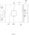
- FIG. 5 is a plan view illustrating an example of a rear surface mold in the injection mold according to an embodiment of the present invention.
- FIG. 6 is a plan view illustrating another example of the rear surface mold in the injection mold according to an embodiment of the present invention.
- the rear surface mold 200 may be provided in a split type.
- the rear surface mold 200 may comprise a first split mold 210, and a second split mold 220 which is disposed at a central portion of the first split mold 210 on a plan view.
- the second split mold 220 may move upward relative to the first split mold 210 after the injection, and the injection-molded product M may be easily separated from the rear surface mold 200.
- a rear surface mold 200' may comprise a first split mold 210, and a second split mold 220' which is disposed on an edge of the first split mold 210 on a plan view. That is, each of the second split molds 220 and 220' may be disposed at a central portion or an edge of the first split mold 210 (see FIGS. 5 and 6 ).
- the edge of the first split mold 210' may be an edge of a portion on which the injection-molded product M is formed in the first split mold 210.
- a cross-section of the second split mold 220 may be formed in a quadrangle shape.
- a coupling hole 212 corresponding to the second split mold 220 may be formed in the first split mold 210 so that the second split mold 220 is coupled to the first split mold.
- a cross-section of the second split mold 220' may be formed in a circular shape.
- a rear surface part 221' of the second split mold 220' may be formed in a circular shape on a plan view.
- Manufactured was an injection mold comprising a transfer mold, which is disposed in front of an injection-molded product to form a pattern on a front surface of the injection-molded product, and a rear surface mold, which is disposed behind the injection-molded product.
- the rear surface mold was formed as a mold in a two-part split type, comprising a first split mold, and a second split mold disposed at a central portion of the first split mold on a plan view.
- An embossing pattern was formed on a front surface part of the transfer mold, which faces the front surface of the injection-molded product.
- a chemical etching process was performed so that the embossing pattern, which is formed on the front surface part of the transfer mold, has a roughness Ra of 10 ⁇ m.
- a rear surface part of the rear surface mold which faces a rear surface of the injection-molded product, was made of a Porcerax material that is a heat dissipating metal.
- the rear surface part of the rear surface mold was processed by surface polishing after the discharging.
- An injection mold was manufactured using the same method as Embodiment 1, except that a rear surface part of a rear surface mold is formed without surface treatment, after the discharging.
- An injection mold was manufactured using the same method as Embodiment 1, except that a rear surface part of a rear surface mold is not split, and ordinary mold steel (HP4M) is applied thereto.
- HP4M ordinary mold steel
- An injection mold was manufactured using the same method as Embodiment 1, except that ordinary mold steel (HP4M) is applied to a rear surface part of a rear surface mold.
- HP4M ordinary mold steel
- An injection mold was manufactured using the same method as Embodiment 1, except that a Be-Cu metal material is applied to a rear surface part of a rear surface mold.
- An injection mold was manufactured using the same method as Embodiment 1, except that a Telfon (PTFE) material is applied to a rear surface part of a rear surface mold.
- PTFE Telfon
- Samples for evaluating appearances of the injection-molded products which were manufactured by Manufacturing Examples 1 and 2 and Comparative Examples 1 to 4, were manufactured under the same molding conditions by applying Ls Mtron LGE-II 220N electric molding machine.
- All measurements in the experiment results mean appearance surfaces on top surfaces of the micro-embo patterned injection-molded products.
- a change in outer appearance of the top surfaces according to split positions of the rear surface according to a degree of embossing pattern transfer may be observed through naked eyes.
- the degree of transfer was evaluated, and a confocal microscope was used to measure a change in roughness Ra at the positions at which the outer appearance is changed, and a thickness of a line on which the change of the roughness Ra continues.
- Table 1 The results of measurements are shown in Table 1 below.
- the sense of difference due to the different degree in embossing pattern transfer according to the results observed through the naked eyes may be recognized when the change in roughness Ra is ⁇ 0.5 um (5%) or more and when the thickness in boundary line is 2 mm or more.
- Table 1 it may be seen that the sense of difference does not occur in Manufacturing Examples 1 and 2, whereas the sense of difference occurs in Comparative Examples 1 to 4.
- the rear surface part of the rear surface mold, which faces the rear surface of the injection-molded product is made of a Porcerax material that is a heat dissipating metal, uniform transfer is achieved.
Landscapes
- Engineering & Computer Science (AREA)
- Mechanical Engineering (AREA)
- Manufacturing & Machinery (AREA)
- Physics & Mathematics (AREA)
- Thermal Sciences (AREA)
- Moulds For Moulding Plastics Or The Like (AREA)
- Injection Moulding Of Plastics Or The Like (AREA)
- Diaphragms For Electromechanical Transducers (AREA)
- Pens And Brushes (AREA)
Abstract
Description
- The present application claims the benefit of the priority of
Korean Patent Application No. 10-2021-0031020, filed on March 9, 2021 - The present invention relates to an injection mold.
- Injection molding is a process for molding an injection-molded product by injecting, into an injection mold, a material to be injection-molded, which is melted by applying heat.
- Many parts of vehicles and electronic products have been manufactured by injection molding, and parts having various exterior designs have been provided by using patterns engraved in an injection mold. A design demanded by exterior parts may be a glossy surface (specular surface), but there has been a gradual increase in selection of micro-embossing patterns in order to give an aesthetical function such as textures, and give surface properties such as scratch and stain resistance. However, there is a phenomenon in which the micro-embossing patterns are not uniformly transferred during the injection molding, depending on the structure of the mold, and the resulting gloss difference leads to the frequent occurrence of a phenomenon in which the exterior surface of the molded article is unevenly reflected. Injection-molded products, on which typical embossing patterns are engraved, are generally applied without post processing such as coating/plating, and concealment by the post processing is impossible. Thus, the aesthetical problem with the surfaces becoming dappled is a serious problem, which needs to be urgently solved.
- [Prior art document] (Patent document)
Korean Patent Registration No. 10-2189820 - One aspect of the present invention is to provide an injection mold capable of implementing uniform transfer onto an injection-molded product.
- The injection mold according to an embodiment of the present invention is an injection mold for manufacturing an injection-molded product through injection molding, comprising: a transfer mold, which is disposed in front of the injection-molded product and forms a pattern on a front surface of the injection-molded product; and a rear surface mold which is disposed behind the injection-molded product. A rear surface part of the rear surface mold, which faces a rear surface of the injection-molded product, may comprise a heat dissipating metal.
- In addition, an injection-molded product according to an embodiment of the present invention may be manufactured by the injection mold according to an embodiment of the present invention.
- According to the present invention, the rear surface part of the rear surface mold, which faces the rear surface of the injection-molded product, may be made of the heat dissipating metal to realize the effects of achieving the uniform transfer and preventing the outer appearance of the injection-molded product from being deteriorated when the transfer mold forms the pattern on the front surface of the injection-molded product.
-
-
FIG. 1 is a cross-sectional view illustrating an injection mold according to an embodiment of the present invention. -
FIG. 2 is an enlarged cross-sectional view illustrating an area A inFIG. 1 . -
FIG. 3 is an enlarged image showing an example of an area B inFIG. 1 . -
FIG. 4 is an enlarged image showing another example of the area B inFIG. 1 . -
FIG. 5 is a plan view illustrating an example of a rear surface mold in the injection mold according to an embodiment of the present invention. -
FIG. 6 is a plan view illustrating another example of the rear surface mold in the injection mold according to an embodiment of the present invention. - The purpose, specified advantages, and novel features of the present invention will be clarified through following embodiments described with reference to the accompanying drawings. Note that the same or similar components in the drawings are designated by the same reference numerals as far as possible even if they are shown in different drawings. The present invention may be embodied in different forms and should not be construed as limited by the embodiments set forth herein. Moreover, in the following description of the present invention, the detailed descriptions of the related well-known art, which may unnecessarily obscure subject matters of the present invention, will be ruled out.
-
FIG. 1 is a cross-sectional view illustrating an injection mold according to an embodiment of the present invention. - Referring to
FIG. 1 , aninjection mold 10 according to an embodiment of the present invention is an injection mold for manufacturing an injection-molded product M through injection molding, comprising atransfer mold 100, which forms a pattern on a front surface of the injection-molded product M, and arear surface mold 200, which is disposed behind the injection-molded product M. Each ofrear surface parts rear surface mold 200, which face a rear surface of the injection-molded product M, comprises a heat dissipating metal. -
FIG. 2 is an enlarged cross-sectional view illustrating an area A inFIG. 1 . - In more detail, referring to
FIGS. 1 and2 , thetransfer mold 100 may be disposed in front of the injection-molded product M to form the pattern on the front surface of the injection-molded product M. Here, the front surface of the injection-molded product M means a surface on a front side of the injection-molded product M. Referring toFIG. 1 , the front surface may be a surface on an upper side of the injection-molded product M. - In addition, the pattern may be formed on a
front surface part 111 of thetransfer mold 100, which faces the front surface of the injection-molded product M, so that the pattern is transferred onto the injection-molded product. An embossing pattern may be formed on thefront surface part 111 of thetransfer mold 100. Here, thefront surface part 111 of thetransfer mold 100 may be processed by chemical etching to have roughness on a surface thereof. - For example, the embossing pattern, which is formed on the
front surface part 111 of thetransfer mold 100, may have a roughness Ra of, for example, 50 um or less. Specifically, for example, the roughness Ra of the embossing pattern, which is formed on thefront surface part 111, may be 5.8 um to 30 um. More specifically, for example, the roughness Ra of the embossing pattern, which is formed on thefront surface part 111, may be 10 um. - Referring to
FIG. 1 , therear surface mold 200 may be disposed behind the injection-molded product M to support the rear surface of the injection-molded product M. Here, the rear surface of the injection-molded product M means a surface on a rear side of the injection-molded product M. Referring toFIG. 1 , the rear surface may be a surface on a lower side of the injection-molded product M. For example, therear surface mold 200 may be disposed below the injection-molded product M. - Each of the
rear surface parts rear surface mold 200, which face the rear surface of the injection-molded product M, may comprise a heat dissipating metal. The heat dissipating metal may be made of a Porcerax material. - Thus, the
injection mold 10 according to an embodiment of the present invention, which is configured as above, has an effect of achieving uniform transfer during injection because each of therear surface parts rear surface mold 200, which face the injection-molded product M, comprises the heat dissipating metal. - Particularly, in the
rear surface mold 200 having a split structure, since each of therear surface parts -
FIG. 3 is an enlarged image showing an example of an area B inFIG. 1 .FIG. 4 is an enlarged image showing another example of the area B inFIG. 1 . - Referring to
FIG. 3 , in an example, therear surface parts rear surface mold 200 may be processed through the discharging. Each of therear surface parts rear surface parts rear surface mold 200 may have a gas vent function using a vent structure with an air pore shape. - Referring to
FIG. 4 , in another example, therear surface parts rear surface mold 200 may be processed by surface milling or polishing after the discharging. -
FIG. 5 is a plan view illustrating an example of a rear surface mold in the injection mold according to an embodiment of the present invention.FIG. 6 is a plan view illustrating another example of the rear surface mold in the injection mold according to an embodiment of the present invention. - Referring to
FIGS. 1 and5 , therear surface mold 200 may be provided in a split type. In an example, therear surface mold 200 may comprise afirst split mold 210, and asecond split mold 220 which is disposed at a central portion of thefirst split mold 210 on a plan view. - Accordingly, the
second split mold 220 may move upward relative to thefirst split mold 210 after the injection, and the injection-molded product M may be easily separated from therear surface mold 200. - Referring to
FIG. 6 , in another example, a rear surface mold 200' may comprise afirst split mold 210, and a second split mold 220' which is disposed on an edge of thefirst split mold 210 on a plan view. That is, each of thesecond split molds 220 and 220' may be disposed at a central portion or an edge of the first split mold 210 (seeFIGS. 5 and6 ). The edge of the first split mold 210' may be an edge of a portion on which the injection-molded product M is formed in thefirst split mold 210. Referring toFIG. 5 , in an example, a cross-section of thesecond split mold 220 may be formed in a quadrangle shape. Acoupling hole 212 corresponding to thesecond split mold 220 may be formed in thefirst split mold 210 so that thesecond split mold 220 is coupled to the first split mold. - Referring to
FIG. 6 , in another example, a cross-section of the second split mold 220' may be formed in a circular shape. A rear surface part 221' of the second split mold 220' may be formed in a circular shape on a plan view. - Manufactured was an injection mold comprising a transfer mold, which is disposed in front of an injection-molded product to form a pattern on a front surface of the injection-molded product, and a rear surface mold, which is disposed behind the injection-molded product. In addition, the rear surface mold was formed as a mold in a two-part split type, comprising a first split mold, and a second split mold disposed at a central portion of the first split mold on a plan view.
- An embossing pattern was formed on a front surface part of the transfer mold, which faces the front surface of the injection-molded product. A chemical etching process was performed so that the embossing pattern, which is formed on the front surface part of the transfer mold, has a roughness Ra of 10 µm.
- A rear surface part of the rear surface mold, which faces a rear surface of the injection-molded product, was made of a Porcerax material that is a heat dissipating metal. The rear surface part of the rear surface mold was processed by surface polishing after the discharging.
- In addition, an ASA resin was used as a material to be injected.
- An injection mold was manufactured using the same method as Embodiment 1, except that a rear surface part of a rear surface mold is formed without surface treatment, after the discharging.
- An injection mold was manufactured using the same method as Embodiment 1, except that a rear surface part of a rear surface mold is not split, and ordinary mold steel (HP4M) is applied thereto.
- An injection mold was manufactured using the same method as Embodiment 1, except that ordinary mold steel (HP4M) is applied to a rear surface part of a rear surface mold.
- An injection mold was manufactured using the same method as Embodiment 1, except that a Be-Cu metal material is applied to a rear surface part of a rear surface mold.
- An injection mold was manufactured using the same method as Embodiment 1, except that a Telfon (PTFE) material is applied to a rear surface part of a rear surface mold.
- Samples for evaluating appearances of the injection-molded products, which were manufactured by Manufacturing Examples 1 and 2 and Comparative Examples 1 to 4, were manufactured under the same molding conditions by applying Ls Mtron LGE-II 220N electric molding machine.
- All measurements in the experiment results mean appearance surfaces on top surfaces of the micro-embo patterned injection-molded products. A change in outer appearance of the top surfaces according to split positions of the rear surface according to a degree of embossing pattern transfer may be observed through naked eyes. In order to quantify characteristics of change in outer appearance of injection-molded products, the degree of transfer was evaluated, and a confocal microscope was used to measure a change in roughness Ra at the positions at which the outer appearance is changed, and a thickness of a line on which the change of the roughness Ra continues. The results of measurements are shown in Table 1 below. (Confocal microscope: Keynence VK-X1100)
[Table 1] Change in roughness on boundary of split component (µm) Thickness in boundary line (mm) Manufacturing Example 1 0.1999 0.28 Manufacturing Example 2 0.228 0.33 Comparative Example 1 -0.048 0.5 Comparative Example 2 1.595 2.55 Comparative Example 3 2.502 2.1 Comparative Example 4 -2.912 3.89 - In the difference in embossing pattern on the split positions of the rear surface, the sense of difference due to the different degree in embossing pattern transfer according to the results observed through the naked eyes may be recognized when the change in roughness Ra is ±0.5 um (5%) or more and when the thickness in boundary line is 2 mm or more. As shown in Table 1, it may be seen that the sense of difference does not occur in Manufacturing Examples 1 and 2, whereas the sense of difference occurs in Comparative Examples 1 to 4. Thus, it is seen that, when the rear surface part of the rear surface mold, which faces the rear surface of the injection-molded product, is made of a Porcerax material that is a heat dissipating metal, uniform transfer is achieved.
- Although the present invention has been described with reference to the limited embodiments, the embodiments are merely intended to specifically describe the present invention, and the present invention is not limited thereto. The present invention may be variously implemented by those of ordinary skill in the art within the technical idea of the present invention.
- The specific protective scope of the present invention will become apparent from the appended claims.
-
- 10:
- Injection mold
- 100:
- Transfer mold
- 111:
- Front surface part
- 200:
- Rear surface mold
- 211, 221:
- Rear surface part
- 212:
- Coupling hole
- 220:
- Second split mold
- 211, 221:
- Rear surface part
- M:
- Injection-molded product
Claims (10)
- An injection mold for manufacturing an injection-molded product through injection molding, the injection mold comprising:a transfer mold disposed in front of the injection-molded product and configured to form a pattern on a front surface of the injection-molded product; anda rear surface mold disposed behind the injection-molded product,wherein a rear surface part of the rear surface mold, which faces a rear surface of the injection-molded product, comprises a heat dissipating metal.
- The injection mold of claim 1, wherein the heat dissipating metal is made of a Porcerax material.
- The injection mold of claim 2, wherein the rear surface part of the rear surface mold is processed through discharging.
- The injection mold of claim 2, wherein the rear surface part of the rear surface mold is processed by surface milling or polishing after discharging.
- The injection mold of claim 1, wherein the rear surface mold is provided in a split type.
- The injection mold of claim 5, wherein the rear surface mold comprises a first split mold, and a second split mold which is disposed at a central portion or an edge of the first split mold on a plan view.
- The injection mold of claim 6, wherein a coupling hole having a shape corresponding to the second split mold is formed in the first split mold so that the second split mold is coupled to the first split mold.
- The injection mold of claim 6, wherein each of rear surface parts of the first split mold and the second split mold, which face the rear surface of the injection-molded product, comprises the heat dissipating metal, and
the heat dissipating metal is made of a Porcerax material. - The injection mold of claim 1, wherein an embossing pattern is formed on a front surface part of the transfer mold, which faces the front surface of the injection-molded product, so that an embossed pattern is formed on the front surface of the injection-molded product.
- An injection-molded product manufactured by the injection mold according to any one of claims 1 to 9.
Applications Claiming Priority (2)
| Application Number | Priority Date | Filing Date | Title |
|---|---|---|---|
| KR1020210031020A KR102782529B1 (en) | 2021-03-09 | 2021-03-09 | Injection mold |
| PCT/KR2022/003202 WO2022191548A1 (en) | 2021-03-09 | 2022-03-07 | Injection mold |
Publications (2)
| Publication Number | Publication Date |
|---|---|
| EP4186675A1 true EP4186675A1 (en) | 2023-05-31 |
| EP4186675A4 EP4186675A4 (en) | 2024-03-13 |
Family
ID=83228053
Family Applications (1)
| Application Number | Title | Priority Date | Filing Date |
|---|---|---|---|
| EP22767444.7A Pending EP4186675A4 (en) | 2021-03-09 | 2022-03-07 | INJECTION MOLD |
Country Status (6)
| Country | Link |
|---|---|
| US (1) | US12472669B2 (en) |
| EP (1) | EP4186675A4 (en) |
| JP (1) | JP7666808B2 (en) |
| KR (1) | KR102782529B1 (en) |
| CN (1) | CN116249608A (en) |
| WO (1) | WO2022191548A1 (en) |
Family Cites Families (35)
| Publication number | Priority date | Publication date | Assignee | Title |
|---|---|---|---|---|
| JPH0664005A (en) * | 1992-08-21 | 1994-03-08 | Honda Motor Co Ltd | Injection mold |
| JPH0732426A (en) | 1993-07-20 | 1995-02-03 | Japan Synthetic Rubber Co Ltd | Manufacturing method of molded products for push button switches |
| US5439622A (en) * | 1993-09-07 | 1995-08-08 | Motorola, Inc. | Method and apparatus for producing molded parts |
| JPH07205748A (en) * | 1994-01-21 | 1995-08-08 | Bridgestone Corp | Manufacture of pad cover for air bag |
| WO1998034770A1 (en) * | 1997-02-10 | 1998-08-13 | Kaneka Corporation | Skin-carrying in-mold expanded molded body manufacturing method, the molded body, and mold used for manufacturing the same |
| JP2877803B1 (en) | 1998-03-31 | 1999-04-05 | 三洋電機株式会社 | Resin molding die, production method thereof, and resin molding method |
| JP2000280304A (en) * | 1999-03-30 | 2000-10-10 | Suzuki Motor Corp | Resin injection molding equipment |
| US6475423B1 (en) * | 1999-12-10 | 2002-11-05 | Slipmate Company | Hybrid injection molding process for enhancing exterior appearance of molded articles by molding fabric thereto |
| JP2002113751A (en) | 2000-10-06 | 2002-04-16 | Sintokogio Ltd | Method for molding internal reflector and mold for molding internal reflector |
| JP3767465B2 (en) | 2001-11-27 | 2006-04-19 | 松下電工株式会社 | Method for producing thin-walled molded product and molding die apparatus used therefor |
| KR100493742B1 (en) * | 2002-03-15 | 2005-06-10 | 주식회사 현동 | Injection Molding Method of the Products having a Pattern on the Surface |
| IL166459A0 (en) | 2002-09-19 | 2006-01-15 | Husky Injection Molding | Cooling tube and method of use thereof |
| TWI235103B (en) | 2003-11-18 | 2005-07-01 | Asia Optical Co Inc | Molding mechanism for high precision optical lens |
| JP2005238456A (en) | 2004-02-24 | 2005-09-08 | Sumitomo Chemical Co Ltd | Manufacturing method for uneven large-sized light guide plate |
| JP4815898B2 (en) | 2004-06-29 | 2011-11-16 | コニカミノルタオプト株式会社 | Injection mold and injection molding method |
| JP2006142521A (en) | 2004-11-17 | 2006-06-08 | Ricoh Co Ltd | Injection molding method, molding mold and molded product |
| JP4335225B2 (en) * | 2006-04-19 | 2009-09-30 | 株式会社日本製鋼所 | Method and apparatus for manufacturing resin molded body |
| KR101282250B1 (en) * | 2006-05-12 | 2013-07-10 | 삼성전자주식회사 | Mold apparatus and portable computer manufactured thereby |
| US20080054049A1 (en) * | 2006-09-01 | 2008-03-06 | Lear Corporation | Mold and method for making a trim component |
| JP5176618B2 (en) | 2008-03-17 | 2013-04-03 | 株式会社村田製作所 | Imprint mold and imprint method using the same |
| CN101980848A (en) * | 2008-03-31 | 2011-02-23 | 柯尼卡美能达精密光学株式会社 | Optical element manufacturing method, optical element molding die, and optical element |
| JP5360679B2 (en) | 2008-12-12 | 2013-12-04 | 株式会社リコー | Thermal control mold for injection molding and manufacturing method thereof |
| WO2013047606A1 (en) * | 2011-09-30 | 2013-04-04 | 株式会社カネカ | Molded resin body for surface-mounted light-emitting device, manufacturing method thereof, and surface-mounted light-emitting device |
| KR101409438B1 (en) | 2012-04-30 | 2014-06-19 | (주)대동아이텍 | Method for forming patterns in injection molding |
| KR101426266B1 (en) * | 2012-12-20 | 2014-08-06 | 한국생산기술연구원 | Manufacturing method of three-dimensions cooling mold and junction device of the same |
| KR101557222B1 (en) | 2014-03-21 | 2015-10-05 | 주식회사 동원테크 | Apparatus for making door trim for automabile by vacuum and injection mold and method for the same |
| CN106163783A (en) * | 2014-04-23 | 2016-11-23 | 横滨橡胶株式会社 | Airtyred manufacture method and manufacture device |
| KR102321060B1 (en) | 2015-05-15 | 2021-11-04 | 레이몰드 주식회사 | Injecion mold |
| JP6622545B2 (en) | 2015-10-08 | 2019-12-18 | 東芝機械株式会社 | Glass forming apparatus and glass forming method |
| JP6528282B2 (en) | 2016-03-09 | 2019-06-12 | パナソニックIpマネジメント株式会社 | In-mold forming film, in-mold forming method and in-mold forming apparatus |
| JP6488506B2 (en) * | 2016-08-22 | 2019-03-27 | トーノファインプレーティング株式会社 | Mold having surface uneven structure, method for producing the same, and method for producing antiglare resin structure using the die |
| JP2020121409A (en) * | 2017-05-25 | 2020-08-13 | 日産自動車株式会社 | Molding die and molding method |
| KR102011905B1 (en) | 2018-11-27 | 2019-08-21 | 주은테크 주식회사 | Injection mold for diversifying embo pattern |
| KR102189820B1 (en) | 2019-04-25 | 2020-12-14 | 덕양산업 주식회사 | Injection mold for vehicle panel that can punch operation |
| KR102790899B1 (en) * | 2021-03-09 | 2025-04-04 | 주식회사 엘지화학 | Injection mold |
-
2021
- 2021-03-09 KR KR1020210031020A patent/KR102782529B1/en active Active
-
2022
- 2022-03-07 EP EP22767444.7A patent/EP4186675A4/en active Pending
- 2022-03-07 WO PCT/KR2022/003202 patent/WO2022191548A1/en not_active Ceased
- 2022-03-07 JP JP2023509440A patent/JP7666808B2/en active Active
- 2022-03-07 US US18/024,705 patent/US12472669B2/en active Active
- 2022-03-07 CN CN202280006395.9A patent/CN116249608A/en active Pending
Also Published As
| Publication number | Publication date |
|---|---|
| US12472669B2 (en) | 2025-11-18 |
| KR102782529B1 (en) | 2025-03-18 |
| US20230339161A1 (en) | 2023-10-26 |
| KR20220126577A (en) | 2022-09-16 |
| JP7666808B2 (en) | 2025-04-22 |
| CN116249608A (en) | 2023-06-09 |
| EP4186675A4 (en) | 2024-03-13 |
| WO2022191548A1 (en) | 2022-09-15 |
| JP2023537736A (en) | 2023-09-05 |
Similar Documents
| Publication | Publication Date | Title |
|---|---|---|
| EP4186676A1 (en) | Injection mold | |
| US20080048349A1 (en) | Low-cost plastic spherical mirror | |
| EP2786876A1 (en) | Transfer film for in-mold injection showing three-dimensional pattern, and preparation method thereof | |
| US11619766B2 (en) | Micro- and nano-hot embossing method for optical glass lens arrays | |
| EP1841830B1 (en) | Adhesive sheet having multi-staged air vent channels | |
| EP0644028B1 (en) | Process for the production of molded article with sealed pattern | |
| US12472669B2 (en) | Injection mold | |
| KR101268749B1 (en) | Insert mold transcription film with glossy or lusterless pattern and method for fabricating the same | |
| WO2002064344A1 (en) | Molding metal mold, method of producing molding metal mold, and articles molded by molding metal mold | |
| KR101281833B1 (en) | Insert mold transcription film with lusterless hair-line pattern and method for fabricating the same | |
| US6607306B2 (en) | Resin ferrule for use in optical fiber connector and molding die therefor | |
| CN116495981B (en) | Forming mold and preparation method thereof, and forming method of curved glass | |
| KR20230135925A (en) | Injection mold | |
| JP3789370B2 (en) | Method for producing thermoplastic resin sheet and sheet | |
| US7997889B2 (en) | Method for making hard mold | |
| JP5421081B2 (en) | Mold for injection molding of vehicle parts, vehicle parts, and molding method of vehicle parts | |
| KR20240034593A (en) | Injection mold | |
| KR200333367Y1 (en) | outer decoration product with anodized and tilted glossy faces | |
| Ruehl et al. | Direct Processing of PVD Hard Coatings via Focused Ion Beam Milling for Microinjection Molding. Micromachines 2023, 14, 294 | |
| TWI295226B (en) | Film for in-mold decoration, method for making the same and process for making a product having the same | |
| JP2013184445A (en) | Insert molded product, and method of manufacturing the same | |
| US20040008950A1 (en) | Resin ferrule for use in optical fiber connector and molding die therefor | |
| JP2013142802A (en) | Antireflection film, mold used for production of antireflection film, and production method of mold | |
| JPH08190007A (en) | Optical reflection mirror and its production | |
| CN112026214A (en) | Technological method for forming glass fiber board |
Legal Events
| Date | Code | Title | Description |
|---|---|---|---|
| STAA | Information on the status of an ep patent application or granted ep patent |
Free format text: STATUS: THE INTERNATIONAL PUBLICATION HAS BEEN MADE |
|
| PUAI | Public reference made under article 153(3) epc to a published international application that has entered the european phase |
Free format text: ORIGINAL CODE: 0009012 |
|
| STAA | Information on the status of an ep patent application or granted ep patent |
Free format text: STATUS: REQUEST FOR EXAMINATION WAS MADE |
|
| 17P | Request for examination filed |
Effective date: 20230221 |
|
| AK | Designated contracting states |
Kind code of ref document: A1 Designated state(s): AL AT BE BG CH CY CZ DE DK EE ES FI FR GB GR HR HU IE IS IT LI LT LU LV MC MK MT NL NO PL PT RO RS SE SI SK SM TR |
|
| A4 | Supplementary search report drawn up and despatched |
Effective date: 20240213 |
|
| RIC1 | Information provided on ipc code assigned before grant |
Ipc: B29C 45/37 20060101ALI20240207BHEP Ipc: B29C 33/30 20060101ALI20240207BHEP Ipc: B29C 33/38 20060101ALI20240207BHEP Ipc: B29C 33/42 20060101ALI20240207BHEP Ipc: B29C 45/26 20060101AFI20240207BHEP |
|
| DAV | Request for validation of the european patent (deleted) | ||
| DAX | Request for extension of the european patent (deleted) |