EP4185743B1 - Methods for producing a monocrystalline ingot by horizontal magnetic field czochralski - Google Patents
Methods for producing a monocrystalline ingot by horizontal magnetic field czochralski Download PDFInfo
- Publication number
- EP4185743B1 EP4185743B1 EP21755262.9A EP21755262A EP4185743B1 EP 4185743 B1 EP4185743 B1 EP 4185743B1 EP 21755262 A EP21755262 A EP 21755262A EP 4185743 B1 EP4185743 B1 EP 4185743B1
- Authority
- EP
- European Patent Office
- Prior art keywords
- melt
- ingot
- magnetic field
- neck
- pulling
- Prior art date
- Legal status (The legal status is an assumption and is not a legal conclusion. Google has not performed a legal analysis and makes no representation as to the accuracy of the status listed.)
- Active
Links
Images




Classifications
-
- C—CHEMISTRY; METALLURGY
- C30—CRYSTAL GROWTH
- C30B—SINGLE-CRYSTAL GROWTH; UNIDIRECTIONAL SOLIDIFICATION OF EUTECTIC MATERIAL OR UNIDIRECTIONAL DEMIXING OF EUTECTOID MATERIAL; REFINING BY ZONE-MELTING OF MATERIAL; PRODUCTION OF A HOMOGENEOUS POLYCRYSTALLINE MATERIAL WITH DEFINED STRUCTURE; SINGLE CRYSTALS OR HOMOGENEOUS POLYCRYSTALLINE MATERIAL WITH DEFINED STRUCTURE; AFTER-TREATMENT OF SINGLE CRYSTALS OR A HOMOGENEOUS POLYCRYSTALLINE MATERIAL WITH DEFINED STRUCTURE; APPARATUS THEREFOR
- C30B15/00—Single-crystal growth by pulling from a melt, e.g. Czochralski method
- C30B15/10—Crucibles or containers for supporting the melt
-
- C—CHEMISTRY; METALLURGY
- C30—CRYSTAL GROWTH
- C30B—SINGLE-CRYSTAL GROWTH; UNIDIRECTIONAL SOLIDIFICATION OF EUTECTIC MATERIAL OR UNIDIRECTIONAL DEMIXING OF EUTECTOID MATERIAL; REFINING BY ZONE-MELTING OF MATERIAL; PRODUCTION OF A HOMOGENEOUS POLYCRYSTALLINE MATERIAL WITH DEFINED STRUCTURE; SINGLE CRYSTALS OR HOMOGENEOUS POLYCRYSTALLINE MATERIAL WITH DEFINED STRUCTURE; AFTER-TREATMENT OF SINGLE CRYSTALS OR A HOMOGENEOUS POLYCRYSTALLINE MATERIAL WITH DEFINED STRUCTURE; APPARATUS THEREFOR
- C30B15/00—Single-crystal growth by pulling from a melt, e.g. Czochralski method
- C30B15/20—Controlling or regulating
-
- C—CHEMISTRY; METALLURGY
- C30—CRYSTAL GROWTH
- C30B—SINGLE-CRYSTAL GROWTH; UNIDIRECTIONAL SOLIDIFICATION OF EUTECTIC MATERIAL OR UNIDIRECTIONAL DEMIXING OF EUTECTOID MATERIAL; REFINING BY ZONE-MELTING OF MATERIAL; PRODUCTION OF A HOMOGENEOUS POLYCRYSTALLINE MATERIAL WITH DEFINED STRUCTURE; SINGLE CRYSTALS OR HOMOGENEOUS POLYCRYSTALLINE MATERIAL WITH DEFINED STRUCTURE; AFTER-TREATMENT OF SINGLE CRYSTALS OR A HOMOGENEOUS POLYCRYSTALLINE MATERIAL WITH DEFINED STRUCTURE; APPARATUS THEREFOR
- C30B15/00—Single-crystal growth by pulling from a melt, e.g. Czochralski method
- C30B15/30—Mechanisms for rotating or moving either the melt or the crystal
-
- C—CHEMISTRY; METALLURGY
- C30—CRYSTAL GROWTH
- C30B—SINGLE-CRYSTAL GROWTH; UNIDIRECTIONAL SOLIDIFICATION OF EUTECTIC MATERIAL OR UNIDIRECTIONAL DEMIXING OF EUTECTOID MATERIAL; REFINING BY ZONE-MELTING OF MATERIAL; PRODUCTION OF A HOMOGENEOUS POLYCRYSTALLINE MATERIAL WITH DEFINED STRUCTURE; SINGLE CRYSTALS OR HOMOGENEOUS POLYCRYSTALLINE MATERIAL WITH DEFINED STRUCTURE; AFTER-TREATMENT OF SINGLE CRYSTALS OR A HOMOGENEOUS POLYCRYSTALLINE MATERIAL WITH DEFINED STRUCTURE; APPARATUS THEREFOR
- C30B29/00—Single crystals or homogeneous polycrystalline material with defined structure characterised by the material or by their shape
- C30B29/02—Elements
- C30B29/06—Silicon
-
- C—CHEMISTRY; METALLURGY
- C30—CRYSTAL GROWTH
- C30B—SINGLE-CRYSTAL GROWTH; UNIDIRECTIONAL SOLIDIFICATION OF EUTECTIC MATERIAL OR UNIDIRECTIONAL DEMIXING OF EUTECTOID MATERIAL; REFINING BY ZONE-MELTING OF MATERIAL; PRODUCTION OF A HOMOGENEOUS POLYCRYSTALLINE MATERIAL WITH DEFINED STRUCTURE; SINGLE CRYSTALS OR HOMOGENEOUS POLYCRYSTALLINE MATERIAL WITH DEFINED STRUCTURE; AFTER-TREATMENT OF SINGLE CRYSTALS OR A HOMOGENEOUS POLYCRYSTALLINE MATERIAL WITH DEFINED STRUCTURE; APPARATUS THEREFOR
- C30B30/00—Production of single crystals or homogeneous polycrystalline material with defined structure characterised by the action of electric or magnetic fields, wave energy or other specific physical conditions
- C30B30/04—Production of single crystals or homogeneous polycrystalline material with defined structure characterised by the action of electric or magnetic fields, wave energy or other specific physical conditions using magnetic fields
Definitions
- This invention generally relates to the production of monocrystalline silicon ingots by horizontal magnetic field Czochralski.
- Horizontal magnetic field Czochralski HMCZ methods may be used to produce relatively high quality silicon wafers. Strong convection control under horizontal magnetic field Czochralski enables a relatively smooth axial diameter profile as well as improves the nanotopology due to low dopant striation.
- the magnetic field may change the condition of the ingot-melt interface due to relatively high velocity and complexity of the melt flow.
- ZD zero dislocation
- the ingot crown is grown under controlled conditions with application of the horizontal magnetic field. Controlled growth conditions include longer process times to allow the crown height to be longer (e.g., 250 mm to 450 mm for 300 mm crystals) and in some instances special crown shapes are used.
- Neck growth is conventionally performed under horizontal magnetic field to stabilize the melt temperature near the meniscus. Conventional horizontal magnetic field methods result in longer process times.
- HMCz horizontal magnetic field Czochralski
- JP H11 209197 A describes the production of a silicon single crystal ingot by a magnetic field Czochralski method in which seeding is executed while no magnetic field is applied. Further methods for producing monocrystalline silicon ingots by the Czochralski method are disclosed in KR 2014 0094830 A , US 2009 169460 A1 and US 2012 279438 A1 .
- the present invention is directed to a method for producing a monocrystalline silicon ingot having a neck and a main body suspended from the neck by the horizontal magnetic field Czochralski method.
- An outwardly flaring portion is disposed between the neck and the ingot main body.
- the monocrystalline silicon ingot is grown in an ingot puller apparatus having a heat shield.
- a seed crystal is contacted with a silicon melt held within a crucible.
- the neck is pulled from the silicon melt.
- a horizontal magnetic field is not applied to the melt while the neck is pulled from the melt.
- the crucible is rotated at a crucible rotation rate of 8 rpm or more while pulling the neck from the melt.
- a distance between the melt and a bottom of the heat shield is at least 60 mm while pulling the neck from the melt.
- the outwardly flaring portion is pulled from the melt, wherein a horizontal magnetic field is not applied to the melt while pulling the outwardly flaring portion from the melt.
- the ingot main body is pulled from the melt.
- the main body is suspended from the neck, the outwardly flaring portion being disposed between the neck and the ingot main body.
- a horizontal magnetic field is applied to the melt while the ingot main body is pulled from the melt.
- the present invention provides a method for producing a monocrystalline silicon ingot by the horizontal magnetic field Czochralski method (HMCz).
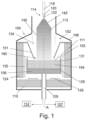
- An ingot puller apparatus (or more simply “ingot puller") for growing a monocrystalline silicon ingot is indicated generally at "100" in Figure 1 .
- the ingot puller apparatus 100 includes a crystal puller housing 108 that defines a growth chamber 152 for pulling a silicon ingot 113 from a melt 104 of silicon.
- the ingot puller apparatus 100 includes a crucible 102 disposed within the growth chamber 152 for holding the melt 104 of silicon.
- the crucible 102 is supported by a susceptor 106.
- the crucible 102 includes a floor 129 and a sidewall 131 that extends upward from the floor 129.
- the sidewall 131 is generally vertical.
- the floor 129 includes the curved portion of the crucible 102 that extends below the sidewall 131.
- a silicon melt 104 having a melt surface 111 (i.e., melt-ingot interface).
- the susceptor 106 is supported by a shaft 105.
- the susceptor 106, crucible 102, shaft 105 and ingot 113 have a common longitudinal axis A or "pull axis" A.
- a pulling mechanism 114 is provided within the ingot puller apparatus 100 for growing and pulling an ingot 113 from the melt 104.
- Pulling mechanism 114 includes a pulling cable 118, a seed holder or chuck 120 coupled to one end of the pulling cable 118, and a seed crystal 122 coupled to the seed holder or chuck 120 for initiating crystal growth.
- One end of the pulling cable 118 is connected to a pulley (not shown) or a drum (not shown), or any other suitable type of lifting mechanism, for example, a shaft, and the other end is connected to the chuck 120 that holds the seed crystal 122.
- the seed crystal 122 is lowered to contact the melt 104.
- the pulling mechanism 114 is operated to cause the seed crystal 122 to rise. This causes a single crystal ingot 113 to be pulled from the melt 104.
- a crucible drive unit 107 e.g., a motor
- a lift mechanism 112 raises and lowers the crucible 102 along the pull axis A during the growth process.
- the crucible 102 and susceptor 106 may be raised to maintain the melt surface 111 at or near the same position relative to the ingot puller apparatus 100.
- a crystal drive unit may also rotate the pulling cable 118 and ingot 113 in a direction opposite the direction in which the crucible drive unit 107 rotates the crucible 102 (e.g., counter-rotation). In embodiments using iso-rotation, the crystal drive unit may rotate the pulling cable 118 in the same direction in which the crucible drive unit 107 rotates the crucible 102. In addition, the crystal drive unit raises and lowers the ingot 113 relative to the melt surface 111 as desired during the growth process.
- the ingot puller apparatus 100 may include an inert gas system to introduce and withdraw an inert gas such as argon from the growth chamber 152.
- the ingot puller apparatus 100 may also include a dopant feed system (not shown) for introducing dopant into the melt 104.
- a quantity of polycrystalline silicon, or polysilicon is charged to the crucible 102 (e.g., charge of 250 kg or more).
- a variety of sources of polycrystalline silicon may be used including, for example, granular polycrystalline silicon produced by thermal decomposition of silane or a halosilane in a fluidized bed reactor or polycrystalline silicon produced in a Siemens reactor.
- the charge is heated to a temperature above about the melting temperature of silicon (e.g., about 1412°C) to melt the charge.
- the charge i.e., the resulting melt
- the ingot puller apparatus 100 includes bottom insulation 110 and side insulation 124 to retain heat in the puller apparatus 100.
- the ingot puller apparatus 100 includes a bottom heater 126 disposed below the crucible floor 129. The crucible 102 may be moved to be in relatively close proximity to the bottom heater 126 to melt the polycrystalline silicon charged to the crucible 102.
- the ingot 113 includes a crown portion 142 in which the ingot transitions and tapers outward from the seed crystal 122 to reach a target diameter.
- the ingot 113 includes a constant diameter portion 145 or cylindrical "main body" of the crystal which is grown by increasing the pull rate.
- the main body 145 of the ingot 113 has a relatively constant diameter.
- the ingot 113 includes a tail or end-cone (not shown) in which the ingot tapers in diameter after the main body 145. When the diameter becomes small enough, the ingot 113 is then separated from the melt 104.
- the ingot 113 has a central longitudinal axis A that extends through the crown portion 142 and a terminal end of the ingot 113.
- the ingot puller apparatus 100 includes a side heater 135 and a susceptor 106 that encircles the crucible 102 to maintain the temperature of the melt 104 during crystal growth.
- the side heater 135 is disposed radially outward to the crucible sidewall 131 as the crucible 102 travels up and down the pull axis A.
- the side heater 135 and bottom heater 126 may be any type of heater that allows the side heater 135 and bottom heater 126 to operate as described herein.
- the heaters 135, 126 are resistance heaters.
- the side heater 135 and bottom heater 126 may be controlled by a control system (not shown) so that the temperature of the melt 104 is controlled throughout the pulling process.
- the ingot puller apparatus 100 also includes a reflector assembly 151 (or simply “reflector” or “heat shield”) disposed within the growth chamber 152 and above the melt 104 which shrouds the ingot 113 during ingot growth.
- the heat shield 151 may be partially disposed within the crucible 102 during crystal growth.
- the heat shield 151 defines a central passage 160 for receiving the ingot 113 as the ingot is pulled by the pulling mechanism 114.
- the reflector 151 is, in general, a heat shield adapted to retain heat underneath itself and above the melt 104.
- any reflector design and material of construction e.g., graphite or gray quartz
- the reflector 151 has a bottom 138 ( Figure 2 ) and the bottom 138 of the reflector 151 is separated from the surface of the melt by a distance Hr during ingot growth.
- the constant diameter portion 145 of the ingot 113 has a circumferential edge 150, a central axis A that is parallel to the circumferential edge 150 and a radius R that extends from the central axis A to the circumferential edge 150.
- the central axis A also passes through the cone 142 and neck 116.
- the diameter of the main ingot body 145 may vary and, in some embodiments, the diameter may be about 150 mm, about 200 mm, about 300 mm, greater than about 300 mm, about 450 mm or even greater than about 450 mm.
- the single crystal silicon ingot 113 may generally have any resistivity.
- the single crystal silicon ingot 113 may be doped or undoped.
- the ingot main body 145 is grown while applying a horizontal magnetic field to the crucible 102 and melt 104 in accordance with known horizontal magnetic field Czochralski techniques (HMCz).
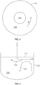
- Figures 4-5 show a horizontal magnetic field applied to a crucible 102 and melt 104 during ingot growth.
- a cylindrical coordinate system for the crucible 102 includes a radial direction R, an angular direction ⁇ , and an axial direction Z.
- the melt 104 may contain one or more convective flow cells 132, 134 induced by heating of the crucible 102 and rotation of the crucible 102 and/or ingot 113 in the angular direction ⁇ .
- the structure and interaction of these one or more convective flow cells 132, 134 may be modulated via regulation of one or more process parameters and/or the application of a horizontal magnetic field as described in detail herein below.
- Figure 6 is a diagram illustrating a horizontal magnetic field applied to the crucible 102 and melt 104 in the ingot puller apparatus 100.
- the crucible 102 contains the silicon melt 104 from which the ingot 113 is grown.
- the transition between the melt and the crystal is generally referred to as the crystal-melt interface (alternatively the melt-crystal, solid-melt or melt-solid interface) and is typically non-linear, for example concave, convex or gull-winged relative to the melt surface.
- Two magnetic poles 157 are placed in opposition to generate a magnetic field generally perpendicular to the crystal-growth direction and generally parallel to the melt surface 111.
- the magnetic poles 157 may be a conventional electromagnet, a superconductor electromagnet, or any other suitable magnet for producing a horizontal magnetic field of the desired strength.
- Application of a horizontal magnetic field gives rise to Lorentz force along the axial direction, in a direction opposite of fluid motion, with opposing forces driving melt convection.
- the convection in the melt is thus suppressed, and the axial temperature gradient in the crystal near the interface increases.
- the melt-crystal interface then moves upward to the crystal side to accommodate the increased axial temperature gradient in the crystal near the interface and the contribution from the melt convection in the crucible decreases.
- the horizontal configuration has the advantage of efficiency in damping a convective flow at the melt surface 111.
- the position of the magnetic poles 157 relative to the melt surface 111 may be varied to adjust the position of the maximum gauss plane (MGP) relative to the melt surface 111.
- the magnetic poles 157 may be cooled (e.g., water cooled) and/or may include a ferrous shield to reduce stray magnetic fields and to enhance the strength of the field produced.
- the loss of zero dislocation (ZD) structure is generally higher during silicon crystal Cz growth in a horizontal magnetic (HMCZ) field versus growth in a Cusp (or vertical) magnetic field.
- the LZD rate in HMCZ can be lowered with shorter process time by not applying a magnetic field (e.g., a horizontal magnetic field or any type of magnetic field) during neck 116 growth and/or at least a portion of crown 142 growth or by applying a relatively weak horizontal magnetic field (e.g., less than 1500 gauss) during neck 116 growth and/or at least a portion of crown 142 growth.
- a horizontal magnetic field is not applied to the melt while the neck is pulled from the melt.
- a magnetic field is not applied to the melt 104 (i.e., the magnetic poles 157 are not powered) or a relatively weak magnetic field such as 1500 gauss or less is applied.
- a horizontal magnetic field is not applied to the melt while pulling the outwardly flaring portion from the melt.
- the entire crown 142 is formed without a magnetic field being applied to the melt or a relatively weak magnetic field such as 1500 gauss or less is applied. In some embodiments, when the crown diameter is less than 120 mm, a magnetic field is not applied to the melt or a magnetic field is applied with the magnetic flux density being less than 1500 gauss. In some embodiments, the magnetic field flux is ramped up (i.e., increase) during crown growth.
- a horizontal magnetic field is applied to the melt 104 during growth of the constant diameter portion 145.
- a horizontal magnetic field having a magnetic flux density of at least 1500 gauss (e.g., 1500 gauss to 4000 gauss or 2000 gauss to 4000 gauss).
- one or more growth conditions are controlled.
- the crucible 102 is rotated at a crucible rotation rate of 8 rpm or more while pulling the neck 116 from the melt 104.
- the distance (Hr) between the bottom 138 of the reflector 151 and the surface 111 of the melt 104 is at least 60 mm while pulling the neck 116 from the melt 104.
- the pull rate of the neck may be at least 1.5 mm/min or from 1.5 mm/min to 4.5 mm/min.
- a relatively long crown may be used such as a crown having a height of at least 220 mm.
- methods of the present invention have several advantages.
- the process time to produce the ingot may be reduced.
- the convective flow of the melt may be increased.
- the distance (Hr) between the reflector and the melt during neck growth to 60 mm or more
- the neck temperature increases which reduces dislocations in the neck and process time may be reduced.
- Ingots were grown by the horizontal magnetic field Czochralski process (HMCz).
- HMCz horizontal magnetic field Czochralski process
- a set of ingots were grown with a horizontal magnetic field being applied during crown growth ("Group A”).
- a second set of ingots were also grown with a horizontal magnetic field being applied during crown growth but at a faster pull speed (“Group B”).
- a third set of ingots were grown without a magnetic field being applied during crown growth (but applied during growth of the main body of the ingot) ("Group C").
- the time to grow the crown for each set of ingots is shown in Figure 7 .
- the ingots in which a horizontal magnetic field was applied during crown growth took 1.5 times as long to grow than the ingot in which a horizontal magnetic field was not applied during crown growth.
- the longer run time may be attributed to the larger crown height in ingots in which a horizontal magnetic field was applied during crown growth.
- Figure 8 shows the range of neck pull speeds in which zero dislocation was achieved for a variety of reflector distances ("Hr group_1”) and a variety of magnet conditions during neck growth (cusp field being applied during neck growth (“Cusp On”) or no magnetic field being applied during neck growth (“HMCZ off”)). As shown in Figure 8 , in the conditions in which the horizontal magnetic field was not applied, faster neck pull rates were used to ensure zero-dislocation growth.
- Ingots were grown by HMCz with a magnetic field not being applied during neck growth.
- the ingots were grown over a variety of reflector-melt distances ("Neck Hr"). As shown in Figure 9 , as Hr becomes more shallow, the melt flow nearby the neck-melt interface is less able to remove dislocations. The hotter conditions with wide Hr enhances the movement of dislocations in the neck.
- the term "about,” when used in conjunction with ranges of dimensions, concentrations, temperatures or other physical or chemical properties or characteristics, is meant to cover variations that may exist in the upper and/or lower limits of the ranges of the properties or characteristics, including, for example, variations resulting from rounding, measurement methodology or other statistical variation.
Landscapes
- Chemical & Material Sciences (AREA)
- Engineering & Computer Science (AREA)
- Crystallography & Structural Chemistry (AREA)
- Materials Engineering (AREA)
- Metallurgy (AREA)
- Organic Chemistry (AREA)
- Crystals, And After-Treatments Of Crystals (AREA)
Description
- This invention generally relates to the production of monocrystalline silicon ingots by horizontal magnetic field Czochralski.
- Horizontal magnetic field Czochralski (HMCZ) methods may be used to produce relatively high quality silicon wafers. Strong convection control under horizontal magnetic field Czochralski enables a relatively smooth axial diameter profile as well as improves the nanotopology due to low dopant striation. The magnetic field may change the condition of the ingot-melt interface due to relatively high velocity and complexity of the melt flow. To ensure the crystal grows with high zero dislocation (ZD) success, the ingot crown is grown under controlled conditions with application of the horizontal magnetic field. Controlled growth conditions include longer process times to allow the crown height to be longer (e.g., 250 mm to 450 mm for 300 mm crystals) and in some instances special crown shapes are used. Neck growth is conventionally performed under horizontal magnetic field to stabilize the melt temperature near the meniscus. Conventional horizontal magnetic field methods result in longer process times.
- A need exists for methods for producing a monocrystalline silicon ingot by the horizontal magnetic field Czochralski (HMCz) method which may decrease process time for forming the ingot.
-
JP H11 209197 A KR 2014 0094830 A US 2009 169460 A1 andUS 2012 279438 A1 . - This section is intended to introduce the reader to various aspects of art that may be related to various aspects of the invention, which are described and claimed below. This discussion is believed to be helpful in providing the reader with background information to facilitate a better understanding of the various aspects of the present invention. Accordingly, it should be understood that these statements are to be read in this light, and not as admissions of prior art.
- The present invention is directed to a method for producing a monocrystalline silicon ingot having a neck and a main body suspended from the neck by the horizontal magnetic field Czochralski method. An outwardly flaring portion is disposed between the neck and the ingot main body. The monocrystalline silicon ingot is grown in an ingot puller apparatus having a heat shield. A seed crystal is contacted with a silicon melt held within a crucible. The neck is pulled from the silicon melt. A horizontal magnetic field is not applied to the melt while the neck is pulled from the melt. The crucible is rotated at a crucible rotation rate of 8 rpm or more while pulling the neck from the melt. A distance between the melt and a bottom of the heat shield is at least 60 mm while pulling the neck from the melt. The outwardly flaring portion is pulled from the melt, wherein a horizontal magnetic field is not applied to the melt while pulling the outwardly flaring portion from the melt. The ingot main body is pulled from the melt. The main body is suspended from the neck, the outwardly flaring portion being disposed between the neck and the ingot main body. A horizontal magnetic field is applied to the melt while the ingot main body is pulled from the melt.
- Various refinements exist of the features noted in relation to the above-mentioned present invention. Further features may also be incorporated in the above-mentioned present invention as well. These refinements and additional features may exist individually or in any combination. For instance, various features discussed below in relation to any of the illustrated embodiments of the present invention may be incorporated into the above-described present invention, alone or in any combination.
-
-
Figure 1 is a cross-section view of an ingot puller apparatus used to pull a single crystal silicon ingot from a silicon melt; -
Figure 2 is a cross-section of an ingot puller apparatus; -
Figure 3 is a partial front view of a single crystal silicon ingot grown by the Czochralski method; -
Figure 4 is a top view of a crucible of the ingot puller apparatus; -
Figure 5 is a side view of the crucible; -
Figure 6 is a schematic illustrating a horizontal magnetic field applied to the crucible containing a melt; -
Figure 7 is a graph showing crown time for groups of wafers grown while applying a horizontal magnetic field to the crown and while not applying a magnetic field to the crown; -
Figure 8 is a graph showing neck pull speed for zero dislocation neck growth for a variety of reflector heights for necks grown with a cusp magnetic field and with no magnetic field being applied during neck growth; and -
Figure 9 is a graph showing the crown zero-dislocation loss failure rate for a variety of reflector heights during HMCz with a magnetic field not being applied during neck growth. - Corresponding reference characters indicate corresponding parts throughout the drawings.
- The present invention provides a method for producing a monocrystalline silicon ingot by the horizontal magnetic field Czochralski method (HMCz). An ingot puller apparatus (or more simply "ingot puller") for growing a monocrystalline silicon ingot is indicated generally at "100" in
Figure 1 . Theingot puller apparatus 100 includes acrystal puller housing 108 that defines agrowth chamber 152 for pulling asilicon ingot 113 from amelt 104 of silicon. Theingot puller apparatus 100 includes acrucible 102 disposed within thegrowth chamber 152 for holding themelt 104 of silicon. Thecrucible 102 is supported by asusceptor 106. - The
crucible 102 includes afloor 129 and asidewall 131 that extends upward from thefloor 129. Thesidewall 131 is generally vertical. Thefloor 129 includes the curved portion of thecrucible 102 that extends below thesidewall 131. Within thecrucible 102 is asilicon melt 104 having a melt surface 111 (i.e., melt-ingot interface). Thesusceptor 106 is supported by ashaft 105. Thesusceptor 106,crucible 102,shaft 105 andingot 113 have a common longitudinal axis A or "pull axis" A. - A
pulling mechanism 114 is provided within theingot puller apparatus 100 for growing and pulling aningot 113 from themelt 104.Pulling mechanism 114 includes apulling cable 118, a seed holder orchuck 120 coupled to one end of thepulling cable 118, and aseed crystal 122 coupled to the seed holder orchuck 120 for initiating crystal growth. One end of thepulling cable 118 is connected to a pulley (not shown) or a drum (not shown), or any other suitable type of lifting mechanism, for example, a shaft, and the other end is connected to thechuck 120 that holds theseed crystal 122. In operation, theseed crystal 122 is lowered to contact themelt 104. Thepulling mechanism 114 is operated to cause theseed crystal 122 to rise. This causes asingle crystal ingot 113 to be pulled from themelt 104. - During heating and crystal pulling, a crucible drive unit 107 (e.g., a motor) rotates the
crucible 102 andsusceptor 106. Alift mechanism 112 raises and lowers thecrucible 102 along the pull axis A during the growth process. As the ingot grows, thesilicon melt 104 is consumed and the height of the melt in thecrucible 102 decreases. Thecrucible 102 andsusceptor 106 may be raised to maintain themelt surface 111 at or near the same position relative to theingot puller apparatus 100. - A crystal drive unit (not shown) may also rotate the pulling
cable 118 andingot 113 in a direction opposite the direction in which thecrucible drive unit 107 rotates the crucible 102 (e.g., counter-rotation). In embodiments using iso-rotation, the crystal drive unit may rotate the pullingcable 118 in the same direction in which thecrucible drive unit 107 rotates thecrucible 102. In addition, the crystal drive unit raises and lowers theingot 113 relative to themelt surface 111 as desired during the growth process. - The
ingot puller apparatus 100 may include an inert gas system to introduce and withdraw an inert gas such as argon from thegrowth chamber 152. Theingot puller apparatus 100 may also include a dopant feed system (not shown) for introducing dopant into themelt 104. - According to the Czochralski single crystal growth process, a quantity of polycrystalline silicon, or polysilicon, is charged to the crucible 102 (e.g., charge of 250 kg or more). A variety of sources of polycrystalline silicon may be used including, for example, granular polycrystalline silicon produced by thermal decomposition of silane or a halosilane in a fluidized bed reactor or polycrystalline silicon produced in a Siemens reactor. Once polycrystalline silicon is added to the crucible to form a charge, the charge is heated to a temperature above about the melting temperature of silicon (e.g., about 1412°C) to melt the charge. In some embodiments, the charge (i.e., the resulting melt) is heated to a temperature of at least about 1425°C, at least about 1450°C or even at least about 1500°C. The
ingot puller apparatus 100 includesbottom insulation 110 andside insulation 124 to retain heat in thepuller apparatus 100. In the illustrated embodiment, theingot puller apparatus 100 includes abottom heater 126 disposed below thecrucible floor 129. Thecrucible 102 may be moved to be in relatively close proximity to thebottom heater 126 to melt the polycrystalline silicon charged to thecrucible 102. - To form the ingot, the
seed crystal 122 is contacted with thesurface 111 of themelt 104. The pullingmechanism 114 is operated to pull theseed crystal 122 from themelt 104. Theingot 113 includes acrown portion 142 in which the ingot transitions and tapers outward from theseed crystal 122 to reach a target diameter. Theingot 113 includes aconstant diameter portion 145 or cylindrical "main body" of the crystal which is grown by increasing the pull rate. Themain body 145 of theingot 113 has a relatively constant diameter. Theingot 113 includes a tail or end-cone (not shown) in which the ingot tapers in diameter after themain body 145. When the diameter becomes small enough, theingot 113 is then separated from themelt 104. Theingot 113 has a central longitudinal axis A that extends through thecrown portion 142 and a terminal end of theingot 113. - The
ingot puller apparatus 100 includes aside heater 135 and asusceptor 106 that encircles thecrucible 102 to maintain the temperature of themelt 104 during crystal growth. Theside heater 135 is disposed radially outward to thecrucible sidewall 131 as thecrucible 102 travels up and down the pull axis A. Theside heater 135 andbottom heater 126 may be any type of heater that allows theside heater 135 andbottom heater 126 to operate as described herein. In some embodiments, theheaters side heater 135 andbottom heater 126 may be controlled by a control system (not shown) so that the temperature of themelt 104 is controlled throughout the pulling process. - In accordance with the present invention, the
ingot puller apparatus 100 also includes a reflector assembly 151 (or simply "reflector" or "heat shield") disposed within thegrowth chamber 152 and above themelt 104 which shrouds theingot 113 during ingot growth. Theheat shield 151 may be partially disposed within thecrucible 102 during crystal growth. Theheat shield 151 defines acentral passage 160 for receiving theingot 113 as the ingot is pulled by the pullingmechanism 114. - The
reflector 151 is, in general, a heat shield adapted to retain heat underneath itself and above themelt 104. In this regard, any reflector design and material of construction (e.g., graphite or gray quartz) known in the art may be used without limitation. Thereflector 151 has a bottom 138 (Figure 2 ) and thebottom 138 of thereflector 151 is separated from the surface of the melt by a distance Hr during ingot growth. - A single
crystal silicon ingot 113 produced in accordance with the present invention and, generally, the Czochralski method is shown inFigure 3 . Theingot 113 includes aneck 116, an outwardly flaring portion 142 (synonymously "crown" or "cone"), ashoulder 119 and a constant diametermain body 145. Theneck 116 is attached to theseed crystal 122 that was contacted with the melt and withdrawn to form theingot 113. Themain body 145 is suspended from theneck 116. Theneck 116 terminates once thecone portion 142 of theingot 113 begins to form. - The
constant diameter portion 145 of theingot 113 has acircumferential edge 150, a central axis A that is parallel to thecircumferential edge 150 and a radius R that extends from the central axis A to thecircumferential edge 150. The central axis A also passes through thecone 142 andneck 116. The diameter of themain ingot body 145 may vary and, in some embodiments, the diameter may be about 150 mm, about 200 mm, about 300 mm, greater than about 300 mm, about 450 mm or even greater than about 450 mm. - The single
crystal silicon ingot 113 may generally have any resistivity. The singlecrystal silicon ingot 113 may be doped or undoped. - In accordance with the present invention, the ingot
main body 145 is grown while applying a horizontal magnetic field to thecrucible 102 and melt 104 in accordance with known horizontal magnetic field Czochralski techniques (HMCz).Figures 4-5 show a horizontal magnetic field applied to acrucible 102 and melt 104 during ingot growth. A cylindrical coordinate system for thecrucible 102 includes a radial direction R, an angular direction Θ, and an axial direction Z. Themelt 104 may contain one or moreconvective flow cells crucible 102 and rotation of thecrucible 102 and/oringot 113 in the angular direction Θ. The structure and interaction of these one or moreconvective flow cells -
Figure 6 is a diagram illustrating a horizontal magnetic field applied to thecrucible 102 and melt 104 in theingot puller apparatus 100. As shown, thecrucible 102 contains thesilicon melt 104 from which theingot 113 is grown. The transition between the melt and the crystal is generally referred to as the crystal-melt interface (alternatively the melt-crystal, solid-melt or melt-solid interface) and is typically non-linear, for example concave, convex or gull-winged relative to the melt surface. Twomagnetic poles 157 are placed in opposition to generate a magnetic field generally perpendicular to the crystal-growth direction and generally parallel to themelt surface 111. - The
magnetic poles 157 may be a conventional electromagnet, a superconductor electromagnet, or any other suitable magnet for producing a horizontal magnetic field of the desired strength. Application of a horizontal magnetic field gives rise to Lorentz force along the axial direction, in a direction opposite of fluid motion, with opposing forces driving melt convection. The convection in the melt is thus suppressed, and the axial temperature gradient in the crystal near the interface increases. The melt-crystal interface then moves upward to the crystal side to accommodate the increased axial temperature gradient in the crystal near the interface and the contribution from the melt convection in the crucible decreases. The horizontal configuration has the advantage of efficiency in damping a convective flow at themelt surface 111. - The position of the
magnetic poles 157 relative to themelt surface 111 may be varied to adjust the position of the maximum gauss plane (MGP) relative to themelt surface 111. Themagnetic poles 157 may be cooled (e.g., water cooled) and/or may include a ferrous shield to reduce stray magnetic fields and to enhance the strength of the field produced. - The loss of zero dislocation (ZD) structure (quantified by LZD rate) is generally higher during silicon crystal Cz growth in a horizontal magnetic (HMCZ) field versus growth in a Cusp (or vertical) magnetic field. However, the LZD rate in HMCZ can be lowered with shorter process time by not applying a magnetic field (e.g., a horizontal magnetic field or any type of magnetic field) during
neck 116 growth and/or at least a portion ofcrown 142 growth or by applying a relatively weak horizontal magnetic field (e.g., less than 1500 gauss) duringneck 116 growth and/or at least a portion ofcrown 142 growth. - According to the present invention, a horizontal magnetic field is not applied to the melt while the neck is pulled from the melt. In accordance with embodiments of the present invention, once the
seed crystal 122 contacts thesilicon melt 104 and theneck 116 begins grown, a magnetic field is not applied to the melt 104 (i.e., themagnetic poles 157 are not powered) or a relatively weak magnetic field such as 1500 gauss or less is applied. Once theneck 116 is formed, the outwardly flaringcrown 142 begins to be pulled from themelt 104. According to the present invention, a horizontal magnetic field is not applied to the melt while pulling the outwardly flaring portion from the melt. In some embodiments, theentire crown 142 is formed without a magnetic field being applied to the melt or a relatively weak magnetic field such as 1500 gauss or less is applied. In some embodiments, when the crown diameter is less than 120 mm, a magnetic field is not applied to the melt or a magnetic field is applied with the magnetic flux density being less than 1500 gauss. In some embodiments, the magnetic field flux is ramped up (i.e., increase) during crown growth. - Once the desired ingot diameter is reached, the
shoulder 119 is formed to transition toward forming theconstant diameter portion 145 of theingot 113. A horizontal magnetic field is applied to themelt 104 during growth of theconstant diameter portion 145. For example, a horizontal magnetic field having a magnetic flux density of at least 1500 gauss (e.g., 1500 gauss to 4000 gauss or 2000 gauss to 4000 gauss). - To reduce the incidence of dislocations in the
neck 116 during neck growth, one or more growth conditions are controlled. Thecrucible 102 is rotated at a crucible rotation rate of 8 rpm or more while pulling theneck 116 from themelt 104. In addition, the distance (Hr) between the bottom 138 of thereflector 151 and thesurface 111 of themelt 104 is at least 60 mm while pulling theneck 116 from themelt 104. Alternatively or in addition, the pull rate of the neck may be at least 1.5 mm/min or from 1.5 mm/min to 4.5 mm/min. Alternatively or in addition, a relatively long crown may be used such as a crown having a height of at least 220 mm. - Compared with conventional methods for growing a monocrystalline ingot by the horizontal magnetic Czochralski method, methods of the present invention have several advantages. By not applying the horizontal magnetic field during neck growth, the process time to produce the ingot may be reduced. By increasing the crucible rotation rate (to 8 rpm or more), the convective flow of the melt may be increased. By increasing the distance (Hr) between the reflector and the melt during neck growth (to 60 mm or more), the neck temperature increases which reduces dislocations in the neck and process time may be reduced.
- The methods of the present invention are further illustrated by the following Examples. These Examples should not be viewed in a limiting sense.
- Ingots were grown by the horizontal magnetic field Czochralski process (HMCz). A set of ingots were grown with a horizontal magnetic field being applied during crown growth ("Group A"). A second set of ingots were also grown with a horizontal magnetic field being applied during crown growth but at a faster pull speed ("Group B"). A third set of ingots were grown without a magnetic field being applied during crown growth (but applied during growth of the main body of the ingot) ("Group C").
- The time to grow the crown for each set of ingots is shown in
Figure 7 . As shown inFigure 7 , the ingots in which a horizontal magnetic field was applied during crown growth took 1.5 times as long to grow than the ingot in which a horizontal magnetic field was not applied during crown growth. The longer run time may be attributed to the larger crown height in ingots in which a horizontal magnetic field was applied during crown growth. -
Figure 8 shows the range of neck pull speeds in which zero dislocation was achieved for a variety of reflector distances ("Hr group_1") and a variety of magnet conditions during neck growth (cusp field being applied during neck growth ("Cusp On") or no magnetic field being applied during neck growth ("HMCZ off")). As shown inFigure 8 , in the conditions in which the horizontal magnetic field was not applied, faster neck pull rates were used to ensure zero-dislocation growth. - Ingots were grown by HMCz with a magnetic field not being applied during neck growth. The ingots were grown over a variety of reflector-melt distances ("Neck Hr"). As shown in
Figure 9 , as Hr becomes more shallow, the melt flow nearby the neck-melt interface is less able to remove dislocations. The hotter conditions with wide Hr enhances the movement of dislocations in the neck. - As used herein, the term "about," when used in conjunction with ranges of dimensions, concentrations, temperatures or other physical or chemical properties or characteristics, is meant to cover variations that may exist in the upper and/or lower limits of the ranges of the properties or characteristics, including, for example, variations resulting from rounding, measurement methodology or other statistical variation.
- When introducing elements of the present invention or the embodiment(s) thereof, the articles "a," "an," "the," and "said" are intended to mean that there are one or more of the elements. The terms "comprising," "including," "containing," and "having" are intended to be inclusive and mean that there may be additional elements other than the listed elements. The use of terms indicating a particular orientation (e.g., "top," "bottom," "side," etc.) is for convenience of description and does not require any particular orientation of the item described.
Claims (7)
- A method for producing a monocrystalline silicon ingot having a neck, a main body suspended from the neck, and an outwardly flaring portion disposed between the neck and the ingot main body, by the horizontal magnetic field Czochralski method, the monocrystalline silicon ingot being grown in an ingot puller apparatus having a heat shield, the method comprising:contacting a seed crystal with a silicon melt held within a crucible;pulling the neck from the silicon melt, wherein:a horizontal magnetic field is not applied to the melt while the neck is pulled from the melt;the crucible is rotated at a crucible rotation rate of 8 rpm or more while pulling the neck from the melt; anda distance between the melt and a bottom of the heat shield is at least 60 mm while pulling the neck from the melt;pulling the outwardly flaring portion from the melt, wherein a horizontal magnetic field is not applied to the melt while pulling the outwardly flaring portion from the melt; andpulling the ingot main body from the melt, the main body being suspended from the neck, the outwardly flaring portion being disposed between the neck and the ingot main body, wherein a horizontal magnetic field is applied to the melt while the ingot main body is pulled from the melt.
- The method as set forth in claim 1 wherein a magnetic field is not applied to the melt while pulling the outwardly flaring portion.
- The method as set forth in claim 1 or claim 2 wherein a magnetic field is not applied to the melt while pulling the neck from the melt.
- The method as set forth in any one of claims 1 to 3 wherein the distance between the melt and the bottom of the heat shield is at least 40 mm while pulling the outwardly flaring portion from the melt.
- The method as set forth in any one of claims 1 to 3 wherein the distance between the melt and the bottom of the heat shield is at least 60 mm while pulling the outwardly flaring portion from the melt.
- The method as set forth in any one of claims 1 to 5 wherein the neck is grown at a pull rate of at least 1.5 mm/min and less than 4.5 mm/min.
- The method as set forth in any one of claims 1 to 6 wherein the outwardly flaring portion has a height that is at least 220 mm.
Priority Applications (1)
| Application Number | Priority Date | Filing Date | Title |
|---|---|---|---|
| EP24193681.4A EP4488428A1 (en) | 2020-07-24 | 2021-07-23 | Methods for producing a monocrystalline ingot by horizontal magnetic field czochralski |
Applications Claiming Priority (2)
| Application Number | Priority Date | Filing Date | Title |
|---|---|---|---|
| US202063056056P | 2020-07-24 | 2020-07-24 | |
| PCT/US2021/042908 WO2022020684A1 (en) | 2020-07-24 | 2021-07-23 | Methods for producing a monocrystalline ingot by horizontal magnetic field czochralski |
Related Child Applications (2)
| Application Number | Title | Priority Date | Filing Date |
|---|---|---|---|
| EP24193681.4A Division-Into EP4488428A1 (en) | 2020-07-24 | 2021-07-23 | Methods for producing a monocrystalline ingot by horizontal magnetic field czochralski |
| EP24193681.4A Division EP4488428A1 (en) | 2020-07-24 | 2021-07-23 | Methods for producing a monocrystalline ingot by horizontal magnetic field czochralski |
Publications (2)
| Publication Number | Publication Date |
|---|---|
| EP4185743A1 EP4185743A1 (en) | 2023-05-31 |
| EP4185743B1 true EP4185743B1 (en) | 2024-09-18 |
Family
ID=77338907
Family Applications (2)
| Application Number | Title | Priority Date | Filing Date |
|---|---|---|---|
| EP21755262.9A Active EP4185743B1 (en) | 2020-07-24 | 2021-07-23 | Methods for producing a monocrystalline ingot by horizontal magnetic field czochralski |
| EP24193681.4A Pending EP4488428A1 (en) | 2020-07-24 | 2021-07-23 | Methods for producing a monocrystalline ingot by horizontal magnetic field czochralski |
Family Applications After (1)
| Application Number | Title | Priority Date | Filing Date |
|---|---|---|---|
| EP24193681.4A Pending EP4488428A1 (en) | 2020-07-24 | 2021-07-23 | Methods for producing a monocrystalline ingot by horizontal magnetic field czochralski |
Country Status (6)
| Country | Link |
|---|---|
| US (1) | US11767611B2 (en) |
| EP (2) | EP4185743B1 (en) |
| JP (1) | JP7760577B2 (en) |
| CN (1) | CN116234946A (en) |
| TW (1) | TWI873370B (en) |
| WO (1) | WO2022020684A1 (en) |
Citations (1)
| Publication number | Priority date | Publication date | Assignee | Title |
|---|---|---|---|---|
| US20120279438A1 (en) * | 2011-05-03 | 2012-11-08 | Memc Electronic Materials, Inc. | Methods for producing single crystal silicon ingots with reduced incidence of dislocations |
Family Cites Families (16)
| Publication number | Priority date | Publication date | Assignee | Title |
|---|---|---|---|---|
| JPH10279399A (en) * | 1997-03-31 | 1998-10-20 | Super Silicon Kenkyusho:Kk | Single crystal manufacturing method |
| JPH11209197A (en) | 1998-01-23 | 1999-08-03 | Shin Etsu Handotai Co Ltd | Method for producing silicon single crystal |
| US6869477B2 (en) | 2000-02-22 | 2005-03-22 | Memc Electronic Materials, Inc. | Controlled neck growth process for single crystal silicon |
| JP3521862B2 (en) | 2000-10-06 | 2004-04-26 | 三菱住友シリコン株式会社 | Single crystal growth method |
| WO2003016598A1 (en) | 2001-08-15 | 2003-02-27 | Memc Electronic Materials, Inc. | Controlled crown growth process for czochralski single crystal silicon |
| JP3698080B2 (en) | 2001-09-11 | 2005-09-21 | 三菱住友シリコン株式会社 | Single crystal pulling method |
| JP4187998B2 (en) | 2002-05-10 | 2008-11-26 | Sumco Techxiv株式会社 | Single crystal manufacturing method and manufacturing apparatus |
| KR20090015679A (en) | 2007-08-09 | 2009-02-12 | 현대자동차주식회사 | Piercing device of hydroforming mold |
| KR100983195B1 (en) | 2007-12-28 | 2010-09-20 | 주식회사 실트론 | 2-Dimensional Line-Defects Controlled Silicon Ingot, Wafer, Epitaxial Wafer, and Manufacturing Process and Apparatus Therefor |
| KR101422711B1 (en) | 2009-06-18 | 2014-07-23 | 가부시키가이샤 사무코 | Silicon monocrystal and production method for same |
| CN102712548B (en) | 2009-12-31 | 2014-03-26 | 卡勒拉公司 | Methods and compositions using calcium carbonate |
| JP5831436B2 (en) | 2012-12-11 | 2015-12-09 | 信越半導体株式会社 | Method for producing silicon single crystal |
| CN104937148B (en) * | 2013-01-23 | 2019-05-31 | 爱思开矽得荣株式会社 | Single crystal ingot, apparatus and method for producing single crystal ingot |
| KR101446717B1 (en) | 2013-01-23 | 2014-10-06 | 주식회사 엘지실트론 | Ingot having single crystal, apparatus and method for manufacturing the ingot |
| US20200002838A1 (en) | 2018-06-28 | 2020-01-02 | Global Wafers Co., Ltd. | Methods for producing a silicon ingot that involve monitoring a moving average of the ingot neck pull rate |
| KR102576552B1 (en) * | 2019-04-18 | 2023-09-07 | 글로벌웨이퍼스 씨오., 엘티디. | Methods for Growing Single Crystal Silicon Ingots Using the Continuous Czochralski Method |
-
2021
- 2021-05-25 US US17/330,092 patent/US11767611B2/en active Active
- 2021-07-23 WO PCT/US2021/042908 patent/WO2022020684A1/en not_active Ceased
- 2021-07-23 EP EP21755262.9A patent/EP4185743B1/en active Active
- 2021-07-23 EP EP24193681.4A patent/EP4488428A1/en active Pending
- 2021-07-23 CN CN202180052415.1A patent/CN116234946A/en active Pending
- 2021-07-23 TW TW110127217A patent/TWI873370B/en active
- 2021-07-23 JP JP2023504654A patent/JP7760577B2/en active Active
Patent Citations (1)
| Publication number | Priority date | Publication date | Assignee | Title |
|---|---|---|---|---|
| US20120279438A1 (en) * | 2011-05-03 | 2012-11-08 | Memc Electronic Materials, Inc. | Methods for producing single crystal silicon ingots with reduced incidence of dislocations |
Also Published As
| Publication number | Publication date |
|---|---|
| EP4185743A1 (en) | 2023-05-31 |
| TWI873370B (en) | 2025-02-21 |
| US20220025541A1 (en) | 2022-01-27 |
| CN116234946A (en) | 2023-06-06 |
| WO2022020684A1 (en) | 2022-01-27 |
| US11767611B2 (en) | 2023-09-26 |
| EP4488428A1 (en) | 2025-01-08 |
| JP7760577B2 (en) | 2025-10-27 |
| JP2023535079A (en) | 2023-08-15 |
| KR20230043918A (en) | 2023-03-31 |
| TW202208702A (en) | 2022-03-01 |
Similar Documents
| Publication | Publication Date | Title |
|---|---|---|
| EP0745706B1 (en) | Manufacturing method of single crystal | |
| WO2003021011A1 (en) | Process for eliminating neck dislocations during czochralski crystal growth | |
| KR102514915B1 (en) | Dopant Concentration Control in Silicon Melts to Improve Ingot Quality | |
| US20120279438A1 (en) | Methods for producing single crystal silicon ingots with reduced incidence of dislocations | |
| US11767611B2 (en) | Methods for producing a monocrystalline ingot by horizontal magnetic field Czochralski | |
| US12110609B2 (en) | Methods for forming a single crystal silicon ingot with reduced crucible erosion | |
| JP2003002782A (en) | Method and apparatus for pulling silicon single crystal | |
| EP3953504B1 (en) | Process for preparing ingot having reduced distortion at late body length | |
| EP4244412B1 (en) | Ingot puller apparatus having a heat shield disposed below a side heater and methods for preparing an ingot with such apparatus | |
| US20260015768A1 (en) | Magnet ramp profiles during single crystal silicon growth | |
| US11873575B2 (en) | Ingot puller apparatus having heat shields with voids therein | |
| US20250051958A1 (en) | Crucibles having anchors and methods for producing and using same | |
| US20250051957A1 (en) | Crucibles having anchors | |
| US20220145492A1 (en) | Ingot puller apparatus having a heat shield disposed below a side heater and methods for preparing an ingot with such apparatus | |
| JPH10279382A (en) | Single crystal manufacturing method | |
| WO2022100831A1 (en) | Methods for preparing an ingot in an ingot puller apparatus and methods for selecting a side heater length for such apparatus | |
| JPH09227279A (en) | Single crystal growth method | |
| JP2005306669A (en) | Apparatus for pulling up silicon single cryststal and method therefor | |
| KR20140094830A (en) | Ingot having single crystal, apparatus and method for manufacturing the ingot |
Legal Events
| Date | Code | Title | Description |
|---|---|---|---|
| STAA | Information on the status of an ep patent application or granted ep patent |
Free format text: STATUS: UNKNOWN |
|
| STAA | Information on the status of an ep patent application or granted ep patent |
Free format text: STATUS: THE INTERNATIONAL PUBLICATION HAS BEEN MADE |
|
| PUAI | Public reference made under article 153(3) epc to a published international application that has entered the european phase |
Free format text: ORIGINAL CODE: 0009012 |
|
| STAA | Information on the status of an ep patent application or granted ep patent |
Free format text: STATUS: REQUEST FOR EXAMINATION WAS MADE |
|
| 17P | Request for examination filed |
Effective date: 20230203 |
|
| AK | Designated contracting states |
Kind code of ref document: A1 Designated state(s): AL AT BE BG CH CY CZ DE DK EE ES FI FR GB GR HR HU IE IS IT LI LT LU LV MC MK MT NL NO PL PT RO RS SE SI SK SM TR |
|
| DAV | Request for validation of the european patent (deleted) | ||
| DAX | Request for extension of the european patent (deleted) | ||
| STAA | Information on the status of an ep patent application or granted ep patent |
Free format text: STATUS: EXAMINATION IS IN PROGRESS |
|
| 17Q | First examination report despatched |
Effective date: 20231121 |
|
| GRAP | Despatch of communication of intention to grant a patent |
Free format text: ORIGINAL CODE: EPIDOSNIGR1 |
|
| STAA | Information on the status of an ep patent application or granted ep patent |
Free format text: STATUS: GRANT OF PATENT IS INTENDED |
|
| INTG | Intention to grant announced |
Effective date: 20240426 |
|
| GRAS | Grant fee paid |
Free format text: ORIGINAL CODE: EPIDOSNIGR3 |
|
| GRAA | (expected) grant |
Free format text: ORIGINAL CODE: 0009210 |
|
| STAA | Information on the status of an ep patent application or granted ep patent |
Free format text: STATUS: THE PATENT HAS BEEN GRANTED |
|
| AK | Designated contracting states |
Kind code of ref document: B1 Designated state(s): AL AT BE BG CH CY CZ DE DK EE ES FI FR GB GR HR HU IE IS IT LI LT LU LV MC MK MT NL NO PL PT RO RS SE SI SK SM TR |
|
| REG | Reference to a national code |
Ref country code: GB Ref legal event code: FG4D |
|
| REG | Reference to a national code |
Ref country code: CH Ref legal event code: EP |
|
| REG | Reference to a national code |
Ref country code: IE Ref legal event code: FG4D |
|
| REG | Reference to a national code |
Ref country code: DE Ref legal event code: R096 Ref document number: 602021019009 Country of ref document: DE |
|
| REG | Reference to a national code |
Ref country code: LT Ref legal event code: MG9D |
|
| PG25 | Lapsed in a contracting state [announced via postgrant information from national office to epo] |
Ref country code: NO Free format text: LAPSE BECAUSE OF FAILURE TO SUBMIT A TRANSLATION OF THE DESCRIPTION OR TO PAY THE FEE WITHIN THE PRESCRIBED TIME-LIMIT Effective date: 20241218 |
|
| PG25 | Lapsed in a contracting state [announced via postgrant information from national office to epo] |
Ref country code: GR Free format text: LAPSE BECAUSE OF FAILURE TO SUBMIT A TRANSLATION OF THE DESCRIPTION OR TO PAY THE FEE WITHIN THE PRESCRIBED TIME-LIMIT Effective date: 20241219 Ref country code: FI Free format text: LAPSE BECAUSE OF FAILURE TO SUBMIT A TRANSLATION OF THE DESCRIPTION OR TO PAY THE FEE WITHIN THE PRESCRIBED TIME-LIMIT Effective date: 20240918 |
|
| PG25 | Lapsed in a contracting state [announced via postgrant information from national office to epo] |
Ref country code: BG Free format text: LAPSE BECAUSE OF FAILURE TO SUBMIT A TRANSLATION OF THE DESCRIPTION OR TO PAY THE FEE WITHIN THE PRESCRIBED TIME-LIMIT Effective date: 20240918 |
|
| PG25 | Lapsed in a contracting state [announced via postgrant information from national office to epo] |
Ref country code: LV Free format text: LAPSE BECAUSE OF FAILURE TO SUBMIT A TRANSLATION OF THE DESCRIPTION OR TO PAY THE FEE WITHIN THE PRESCRIBED TIME-LIMIT Effective date: 20240918 |
|
| PG25 | Lapsed in a contracting state [announced via postgrant information from national office to epo] |
Ref country code: HR Free format text: LAPSE BECAUSE OF FAILURE TO SUBMIT A TRANSLATION OF THE DESCRIPTION OR TO PAY THE FEE WITHIN THE PRESCRIBED TIME-LIMIT Effective date: 20240918 |
|
| REG | Reference to a national code |
Ref country code: NL Ref legal event code: MP Effective date: 20240918 |
|
| PG25 | Lapsed in a contracting state [announced via postgrant information from national office to epo] |
Ref country code: RS Free format text: LAPSE BECAUSE OF FAILURE TO SUBMIT A TRANSLATION OF THE DESCRIPTION OR TO PAY THE FEE WITHIN THE PRESCRIBED TIME-LIMIT Effective date: 20241218 |
|
| PG25 | Lapsed in a contracting state [announced via postgrant information from national office to epo] |
Ref country code: RS Free format text: LAPSE BECAUSE OF FAILURE TO SUBMIT A TRANSLATION OF THE DESCRIPTION OR TO PAY THE FEE WITHIN THE PRESCRIBED TIME-LIMIT Effective date: 20241218 Ref country code: NO Free format text: LAPSE BECAUSE OF FAILURE TO SUBMIT A TRANSLATION OF THE DESCRIPTION OR TO PAY THE FEE WITHIN THE PRESCRIBED TIME-LIMIT Effective date: 20241218 Ref country code: LV Free format text: LAPSE BECAUSE OF FAILURE TO SUBMIT A TRANSLATION OF THE DESCRIPTION OR TO PAY THE FEE WITHIN THE PRESCRIBED TIME-LIMIT Effective date: 20240918 Ref country code: HR Free format text: LAPSE BECAUSE OF FAILURE TO SUBMIT A TRANSLATION OF THE DESCRIPTION OR TO PAY THE FEE WITHIN THE PRESCRIBED TIME-LIMIT Effective date: 20240918 Ref country code: GR Free format text: LAPSE BECAUSE OF FAILURE TO SUBMIT A TRANSLATION OF THE DESCRIPTION OR TO PAY THE FEE WITHIN THE PRESCRIBED TIME-LIMIT Effective date: 20241219 Ref country code: FI Free format text: LAPSE BECAUSE OF FAILURE TO SUBMIT A TRANSLATION OF THE DESCRIPTION OR TO PAY THE FEE WITHIN THE PRESCRIBED TIME-LIMIT Effective date: 20240918 Ref country code: BG Free format text: LAPSE BECAUSE OF FAILURE TO SUBMIT A TRANSLATION OF THE DESCRIPTION OR TO PAY THE FEE WITHIN THE PRESCRIBED TIME-LIMIT Effective date: 20240918 |
|
| REG | Reference to a national code |
Ref country code: AT Ref legal event code: MK05 Ref document number: 1724764 Country of ref document: AT Kind code of ref document: T Effective date: 20240918 |
|
| PG25 | Lapsed in a contracting state [announced via postgrant information from national office to epo] |
Ref country code: NL Free format text: LAPSE BECAUSE OF FAILURE TO SUBMIT A TRANSLATION OF THE DESCRIPTION OR TO PAY THE FEE WITHIN THE PRESCRIBED TIME-LIMIT Effective date: 20240918 |
|
| PG25 | Lapsed in a contracting state [announced via postgrant information from national office to epo] |
Ref country code: IS Free format text: LAPSE BECAUSE OF FAILURE TO SUBMIT A TRANSLATION OF THE DESCRIPTION OR TO PAY THE FEE WITHIN THE PRESCRIBED TIME-LIMIT Effective date: 20250118 Ref country code: PT Free format text: LAPSE BECAUSE OF FAILURE TO SUBMIT A TRANSLATION OF THE DESCRIPTION OR TO PAY THE FEE WITHIN THE PRESCRIBED TIME-LIMIT Effective date: 20250120 |
|
| PG25 | Lapsed in a contracting state [announced via postgrant information from national office to epo] |
Ref country code: RO Free format text: LAPSE BECAUSE OF FAILURE TO SUBMIT A TRANSLATION OF THE DESCRIPTION OR TO PAY THE FEE WITHIN THE PRESCRIBED TIME-LIMIT Effective date: 20240918 Ref country code: SM Free format text: LAPSE BECAUSE OF FAILURE TO SUBMIT A TRANSLATION OF THE DESCRIPTION OR TO PAY THE FEE WITHIN THE PRESCRIBED TIME-LIMIT Effective date: 20240918 |
|
| PG25 | Lapsed in a contracting state [announced via postgrant information from national office to epo] |
Ref country code: ES Free format text: LAPSE BECAUSE OF FAILURE TO SUBMIT A TRANSLATION OF THE DESCRIPTION OR TO PAY THE FEE WITHIN THE PRESCRIBED TIME-LIMIT Effective date: 20240918 |
|
| PG25 | Lapsed in a contracting state [announced via postgrant information from national office to epo] |
Ref country code: EE Free format text: LAPSE BECAUSE OF FAILURE TO SUBMIT A TRANSLATION OF THE DESCRIPTION OR TO PAY THE FEE WITHIN THE PRESCRIBED TIME-LIMIT Effective date: 20240918 Ref country code: AT Free format text: LAPSE BECAUSE OF FAILURE TO SUBMIT A TRANSLATION OF THE DESCRIPTION OR TO PAY THE FEE WITHIN THE PRESCRIBED TIME-LIMIT Effective date: 20240918 |
|
| PG25 | Lapsed in a contracting state [announced via postgrant information from national office to epo] |
Ref country code: CZ Free format text: LAPSE BECAUSE OF FAILURE TO SUBMIT A TRANSLATION OF THE DESCRIPTION OR TO PAY THE FEE WITHIN THE PRESCRIBED TIME-LIMIT Effective date: 20240918 Ref country code: PL Free format text: LAPSE BECAUSE OF FAILURE TO SUBMIT A TRANSLATION OF THE DESCRIPTION OR TO PAY THE FEE WITHIN THE PRESCRIBED TIME-LIMIT Effective date: 20240918 |
|
| PG25 | Lapsed in a contracting state [announced via postgrant information from national office to epo] |
Ref country code: SK Free format text: LAPSE BECAUSE OF FAILURE TO SUBMIT A TRANSLATION OF THE DESCRIPTION OR TO PAY THE FEE WITHIN THE PRESCRIBED TIME-LIMIT Effective date: 20240918 Ref country code: IT Free format text: LAPSE BECAUSE OF FAILURE TO SUBMIT A TRANSLATION OF THE DESCRIPTION OR TO PAY THE FEE WITHIN THE PRESCRIBED TIME-LIMIT Effective date: 20240918 |
|
| REG | Reference to a national code |
Ref country code: DE Ref legal event code: R097 Ref document number: 602021019009 Country of ref document: DE |
|
| PG25 | Lapsed in a contracting state [announced via postgrant information from national office to epo] |
Ref country code: DK Free format text: LAPSE BECAUSE OF FAILURE TO SUBMIT A TRANSLATION OF THE DESCRIPTION OR TO PAY THE FEE WITHIN THE PRESCRIBED TIME-LIMIT Effective date: 20240918 |
|
| PLBE | No opposition filed within time limit |
Free format text: ORIGINAL CODE: 0009261 |
|
| STAA | Information on the status of an ep patent application or granted ep patent |
Free format text: STATUS: NO OPPOSITION FILED WITHIN TIME LIMIT |
|
| 26N | No opposition filed |
Effective date: 20250619 |
|
| PG25 | Lapsed in a contracting state [announced via postgrant information from national office to epo] |
Ref country code: SE Free format text: LAPSE BECAUSE OF FAILURE TO SUBMIT A TRANSLATION OF THE DESCRIPTION OR TO PAY THE FEE WITHIN THE PRESCRIBED TIME-LIMIT Effective date: 20240918 |
|
| PGFP | Annual fee paid to national office [announced via postgrant information from national office to epo] |
Ref country code: DE Payment date: 20250729 Year of fee payment: 5 |
|
| PGFP | Annual fee paid to national office [announced via postgrant information from national office to epo] |
Ref country code: FR Payment date: 20250725 Year of fee payment: 5 |
|
| REG | Reference to a national code |
Ref country code: CH Ref legal event code: H13 Free format text: ST27 STATUS EVENT CODE: U-0-0-H10-H13 (AS PROVIDED BY THE NATIONAL OFFICE) Effective date: 20260224 |
|
| PG25 | Lapsed in a contracting state [announced via postgrant information from national office to epo] |
Ref country code: LU Free format text: LAPSE BECAUSE OF NON-PAYMENT OF DUE FEES Effective date: 20250723 |
|
| GBPC | Gb: european patent ceased through non-payment of renewal fee |
Effective date: 20250723 |
|
| REG | Reference to a national code |
Ref country code: BE Ref legal event code: MM Effective date: 20250731 |
|
| PG25 | Lapsed in a contracting state [announced via postgrant information from national office to epo] |
Ref country code: GB Free format text: LAPSE BECAUSE OF NON-PAYMENT OF DUE FEES Effective date: 20250723 |
|
| PG25 | Lapsed in a contracting state [announced via postgrant information from national office to epo] |
Ref country code: BE Free format text: LAPSE BECAUSE OF NON-PAYMENT OF DUE FEES Effective date: 20250731 |
|
| PG25 | Lapsed in a contracting state [announced via postgrant information from national office to epo] |
Ref country code: CH Free format text: LAPSE BECAUSE OF NON-PAYMENT OF DUE FEES Effective date: 20250731 |
|
| PG25 | Lapsed in a contracting state [announced via postgrant information from national office to epo] |
Ref country code: LT Free format text: LAPSE BECAUSE OF FAILURE TO SUBMIT A TRANSLATION OF THE DESCRIPTION OR TO PAY THE FEE WITHIN THE PRESCRIBED TIME-LIMIT Effective date: 20240918 |
|
| PG25 | Lapsed in a contracting state [announced via postgrant information from national office to epo] |
Ref country code: IE Free format text: LAPSE BECAUSE OF NON-PAYMENT OF DUE FEES Effective date: 20250723 |
|
| PG25 | Lapsed in a contracting state [announced via postgrant information from national office to epo] |
Ref country code: MC Free format text: LAPSE BECAUSE OF FAILURE TO SUBMIT A TRANSLATION OF THE DESCRIPTION OR TO PAY THE FEE WITHIN THE PRESCRIBED TIME-LIMIT Effective date: 20240918 |
|
| PG25 | Lapsed in a contracting state [announced via postgrant information from national office to epo] |
Ref country code: CY Free format text: LAPSE BECAUSE OF FAILURE TO SUBMIT A TRANSLATION OF THE DESCRIPTION OR TO PAY THE FEE WITHIN THE PRESCRIBED TIME-LIMIT Effective date: 20240918 |