EP4185371B1 - Vestibuläre elektrodenanordnung - Google Patents
Vestibuläre elektrodenanordnung Download PDFInfo
- Publication number
- EP4185371B1 EP4185371B1 EP21846277.8A EP21846277A EP4185371B1 EP 4185371 B1 EP4185371 B1 EP 4185371B1 EP 21846277 A EP21846277 A EP 21846277A EP 4185371 B1 EP4185371 B1 EP 4185371B1
- Authority
- EP
- European Patent Office
- Prior art keywords
- stylet
- vestibular
- electrode array
- elongate carrier
- recipient
- Prior art date
- Legal status (The legal status is an assumption and is not a legal conclusion. Google has not performed a legal analysis and makes no representation as to the accuracy of the status listed.)
- Active
Links
Images


Classifications
-
- A—HUMAN NECESSITIES
- A61—MEDICAL OR VETERINARY SCIENCE; HYGIENE
- A61N—ELECTROTHERAPY; MAGNETOTHERAPY; RADIATION THERAPY; ULTRASOUND THERAPY
- A61N1/00—Electrotherapy; Circuits therefor
- A61N1/18—Applying electric currents by contact electrodes
- A61N1/32—Applying electric currents by contact electrodes alternating or intermittent currents
- A61N1/36—Applying electric currents by contact electrodes alternating or intermittent currents for stimulation
- A61N1/36036—Applying electric currents by contact electrodes alternating or intermittent currents for stimulation of the outer, middle or inner ear
-
- A—HUMAN NECESSITIES
- A61—MEDICAL OR VETERINARY SCIENCE; HYGIENE
- A61B—DIAGNOSIS; SURGERY; IDENTIFICATION
- A61B34/00—Computer-aided surgery; Manipulators or robots specially adapted for use in surgery
- A61B34/30—Surgical robots
-
- A—HUMAN NECESSITIES
- A61—MEDICAL OR VETERINARY SCIENCE; HYGIENE
- A61B—DIAGNOSIS; SURGERY; IDENTIFICATION
- A61B5/00—Measuring for diagnostic purposes; Identification of persons
- A61B5/12—Audiometering
- A61B5/121—Audiometering evaluating hearing capacity
- A61B5/125—Audiometering evaluating hearing capacity objective methods
-
- A—HUMAN NECESSITIES
- A61—MEDICAL OR VETERINARY SCIENCE; HYGIENE
- A61N—ELECTROTHERAPY; MAGNETOTHERAPY; RADIATION THERAPY; ULTRASOUND THERAPY
- A61N1/00—Electrotherapy; Circuits therefor
- A61N1/02—Details
- A61N1/04—Electrodes
- A61N1/05—Electrodes for implantation or insertion into the body, e.g. heart electrode
- A61N1/0526—Head electrodes
-
- A—HUMAN NECESSITIES
- A61—MEDICAL OR VETERINARY SCIENCE; HYGIENE
- A61B—DIAGNOSIS; SURGERY; IDENTIFICATION
- A61B34/00—Computer-aided surgery; Manipulators or robots specially adapted for use in surgery
- A61B34/20—Surgical navigation systems; Devices for tracking or guiding surgical instruments, e.g. for frameless stereotaxis
- A61B2034/2046—Tracking techniques
- A61B2034/2061—Tracking techniques using shape-sensors, e.g. fiber shape sensors with Bragg gratings
-
- A—HUMAN NECESSITIES
- A61—MEDICAL OR VETERINARY SCIENCE; HYGIENE
- A61B—DIAGNOSIS; SURGERY; IDENTIFICATION
- A61B90/00—Instruments, implements or accessories specially adapted for surgery or diagnosis and not covered by any of the groups A61B1/00 - A61B50/00, e.g. for luxation treatment or for protecting wound edges
- A61B90/39—Markers, e.g. radio-opaque or breast lesions markers
- A61B2090/3966—Radiopaque markers visible in an X-ray image
-
- A—HUMAN NECESSITIES
- A61—MEDICAL OR VETERINARY SCIENCE; HYGIENE
- A61N—ELECTROTHERAPY; MAGNETOTHERAPY; RADIATION THERAPY; ULTRASOUND THERAPY
- A61N1/00—Electrotherapy; Circuits therefor
- A61N1/02—Details
- A61N1/04—Electrodes
- A61N1/05—Electrodes for implantation or insertion into the body, e.g. heart electrode
- A61N1/0526—Head electrodes
- A61N1/0541—Cochlear electrodes
-
- A—HUMAN NECESSITIES
- A61—MEDICAL OR VETERINARY SCIENCE; HYGIENE
- A61N—ELECTROTHERAPY; MAGNETOTHERAPY; RADIATION THERAPY; ULTRASOUND THERAPY
- A61N1/00—Electrotherapy; Circuits therefor
- A61N1/18—Applying electric currents by contact electrodes
- A61N1/32—Applying electric currents by contact electrodes alternating or intermittent currents
- A61N1/36—Applying electric currents by contact electrodes alternating or intermittent currents for stimulation
- A61N1/36036—Applying electric currents by contact electrodes alternating or intermittent currents for stimulation of the outer, middle or inner ear
- A61N1/36038—Cochlear stimulation
-
- A—HUMAN NECESSITIES
- A61—MEDICAL OR VETERINARY SCIENCE; HYGIENE
- A61N—ELECTROTHERAPY; MAGNETOTHERAPY; RADIATION THERAPY; ULTRASOUND THERAPY
- A61N1/00—Electrotherapy; Circuits therefor
- A61N1/18—Applying electric currents by contact electrodes
- A61N1/32—Applying electric currents by contact electrodes alternating or intermittent currents
- A61N1/36—Applying electric currents by contact electrodes alternating or intermittent currents for stimulation
- A61N1/3605—Implantable neurostimulators for stimulating central or peripheral nerve system
- A61N1/3606—Implantable neurostimulators for stimulating central or peripheral nerve system adapted for a particular treatment
- A61N1/36067—Movement disorders, e.g. tremor or Parkinson disease
-
- A—HUMAN NECESSITIES
- A61—MEDICAL OR VETERINARY SCIENCE; HYGIENE
- A61N—ELECTROTHERAPY; MAGNETOTHERAPY; RADIATION THERAPY; ULTRASOUND THERAPY
- A61N1/00—Electrotherapy; Circuits therefor
- A61N1/18—Applying electric currents by contact electrodes
- A61N1/32—Applying electric currents by contact electrodes alternating or intermittent currents
- A61N1/36—Applying electric currents by contact electrodes alternating or intermittent currents for stimulation
- A61N1/372—Arrangements in connection with the implantation of stimulators
- A61N1/375—Constructional arrangements, e.g. casings
Definitions
- Medical devices have provided a wide range of therapeutic benefits to recipients over recent decades. Medical devices can include internal or implantable components/devices, external or wearable components/devices, or combinations thereof (e.g., a device having an external component communicating with an implantable component). Medical devices, such as traditional hearing aids, partially or fully-implantable hearing prostheses (e.g., bone conduction devices, mechanical stimulators, cochlear implants, etc.), pacemakers, defibrillators, functional electrical stimulation devices, and other medical devices, have been successful in performing lifesaving and/or lifestyle enhancement functions and/or recipient monitoring for a number of years.
- medical devices such as traditional hearing aids, partially or fully-implantable hearing prostheses (e.g., bone conduction devices, mechanical stimulators, cochlear implants, etc.), pacemakers, defibrillators, functional electrical stimulation devices, and other medical devices, have been successful in performing lifesaving and/or lifestyle enhancement functions and/or recipient monitoring for a number of years.
- US 8 843 217 B1 discloses an apparatus and method for triggering nerve-action potentials in each of a plurality of cochlear neurons in a cochlea of a person and in each one of a plurality of vestibular neurons in a vestibular organ of a person.
- a vestibular implant portion of the apparatus includes stimulation sources including a plurality of vertical-cavity-surface-emitting lasers and/or a plurality of electrodes.
- a transmission medium configured to deliver light signals to a vestibular neuron can include a plurality of optical fibers. The light signals can be used to optically trigger nerve-action potentials.
- An apparatus according to the invention includes the features defined in claim 1.
- Embodiments include the features defined in the dependent claims.
- Sensory impulses relating to balance and spatial orientation are generated by the vestibular system. These sensory impulses are perceived by the brain via the vestibulocochlear nerve and provide a sense of balance and spatial orientation. But disorders affecting the vestibular system (e.g., Méimba's disease or inflammation of vestibular anatomy) can cause vestibular deficiency by interfering with these sensory impulses, thereby negatively affect one's sense of balance and spatial orientation. Vertigo can also result. Treatments for disorders of the vestibular system can include treatment with electrical stimulation via an electrode placed in the recipient's vestibule via the stapes footplate with a final position near the otolithic organs or vestibular nerve.
- Treatments for disorders of the vestibular system can include treatment with electrical stimulation via an electrode placed in the recipient's vestibule via the stapes footplate with a final position near the otolithic organs or vestibular nerve.
- otolith organs which include the saccule and utricle, are fragile and are suspended in the space of the vestibule via fine soft tissue membranes.
- Such treatment targets can be difficult to reach with high accuracy to ensure that electrical stimulation reaches the target structures without substantially stimulating non-target structures (e.g. ampullae of the semicircular canals).
- Traditional approaches for implantation include pushing an electrode array into the vestibule by a set distance or stopping when the electrode array meets a certain amount of resistance. Such blind insertion technique can be challenging to perform.
- Disclosed examples include techniques and devices to facilitate implantation of a vestibular electrode array proximate a target treatment location of the recipient's vestibular system.
- An example vestibular electrode array can include a variety of mechanisms to provide fine control of the vestibular electrode array's position in the vestibular space. Further, the position can be guided by real time feedback mechanisms, such as fluoroscopy or electrophysiological measures to assist with positioning the vestibular electrode array.
- an implanter controls the depth and trajectory of the vestibular stimulation array using a straight or curved stylet.
- the implanter can use the stylet to guide the electrodes of the vestibular electrode array to a target location (e.g., proximate the recipient's inferior vestibular nerve).
- the stylet can be coupled to the vestibular stimulation array, such as by being permanently embedded in the vestibular electrode array.
- the stylet is configured to be removed from a lumen in the vestibular electrode array.
- the stylet can be a curved stylet by having a slight curve at a distal end of the stylet, which can provide fine control of the position of the tip of the vestibular electrode array by rotating the stylet.
- the stylet can take any of a variety of forms and can be made from any of a variety of different materials, such as one or more metals, alloys, polymers, glass, other materials, or combinations thereof.
- the stylet can be constructed to be stiff or malleable (e.g., relative to the vestibular electrode array).
- the stylet can have a shape-memory characteristic instigated by heat or electric current.
- the stylet and or the vestibular electrode array can include smart polymers having a shape controllable by the application of electric current.
- Certain implementations can be such that the stylet is configured to be mounted to the recipient's skull.
- the stylet can be mounted to the recipient's skull to resist the vestibular stimulation array being dislodged from the target treatment location.
- an endoscopic optical fiber bundle integrated with the vestibular electrode array can be used by a clinician to visualize the interior of the vestibule.
- the optical fibers of the optical fiber bundle can be permanently embedded in the vestibular electrode array or can be configured to reside temporarily in a lumen of the vestibular electrode array and be removable after the electrode is fixed in position.
- the lumen can be configured to be closed to avoid leaving an open pathway into the vestibule after implantation.
- a clear window can be located at the tip of the vestibular electrode array so that the distal end of the lumen is not open to the vestibule (e.g., the window seals the distal end of the lumen).
- an open lumen may be closed by partially or completely filling the lumen with a substance or closing off the proximal end of the lumen with a plug or adhesive sealant.
- An alternative to a lumen disposed in the vestibular electrode array for receiving the optical fiber bundle can be a groove along a side of the vestibular electrode array configured to receive the optical fiber bundle. The groove can be sealed with tissue at the entry point after implantation. The optical fiber can be held in place via an interference fit with the groove or through loops (e.g., spans over the groove) that are sufficient to keep the optical fiber bundle in place during implantation.
- the insertion of the vestibular electrode array is conducted under fluoroscopic feedback.
- a radiopaque component in the vestibular electrode array e.g., metal wires, a metal stylet, or a radiopaque marker
- a clinician can view the fluoroscopic feedback and modify a position of the vestibular electrode array based thereon.
- the feedback can be used with an automatic or semi-automatic robotic positioner to adjust the position of the vestibular electrode array during implantation into the vestibule.
- the robotic positioner can control the electrode insertion depth, angle, or other position using, for example, manipulation of a stylet (e.g., as described above) based on the fluoroscopic feedback.
- the insertion of the vestibular electrode array is conducted under real time electrophysiological feedback.
- the electrophysiological feedback can be a response by the recipient to a stimulus.
- the stimulus can be provided and measured by the vestibular electrode array or by one or more other devices.
- the response can be a neural response or a myogenic response to the provided stimulus.
- the electrophysiological feedback can be used to not only monitor implantation of the vestibular electrode array with respect to vestibular anatomy.
- the hearing function of the recipient is monitored during insertion of the vestibular electrode array using, for example, electrocochleography. Such monitoring can be used to facilitate determining implantation's effect on the recipient's residual hearing.
- a device can detect the position of the vestibular electrode array (e.g., the positioning of a distal tip thereof) and emit a sound with a pitch or other feature indicating the proximity of the vestibular electrode array to desirable or undesirable locations. For example, rising pitch can indicate a closer position or better response from a target nerve.
- the feedback that would be provided to the clinician can be provided to an automatic or semi-automatic robot in a suitable format to allow the robot to adjust the position of the electrode in the vestibule.
- the robot can control the electrode insertion depth, angle, or other position using a technique like the stylet invention described above.
- the electronics module 114 can include one or more components that provide vestibular stimulation or other functionality.
- the electronics module 114 includes one or more components for receiving a signal (e.g., from external or implanted devices and sensors) and one or more components for converting the signal into a stimulation signal, such as a transceiver and an antenna.
- the electronics module 114 generates a stimulation signal without regard to a signal from an external device.
- the stimulation signal is generated according to a predetermined stimulation schedule that defines when and at what intensity the stimulation is to be applied, and the electronics module can include one or more components defining the stimulation schedule.
- the micropositioner 212 can be a manually-manipulatable device that permits a clinician to finely control the position of the vestibular electrode array 140.
- the micropositioner 212 can permit a user to more finely control a position of the vestibular electrode array 140 than the user would be able to without the micropositioner 212.
- the vestibular electrode array 140, the stylet 190, or another component can be coupled to the micropositioner 212 such that manipulation of the micropositioner 212 causes movement of the vestibular electrode array 140.
- the micropositioner 212 can be or include a universal joint that can be used to manipulate the stylet 190 and lock the stylet 190 in place as needed.
- the sealant 214 and plug 216 can be components configured to seal or plug an opening in a component of the kit 200.
- the vestibular electrode array 140 can include a lumen for carrying the optical fiber bundle 220.
- the sealant 214 or plug 216 can be configured to seal an opening of the lumen of the elongate carrier.
- the sealant 214 is a paste contained in a tube that, when applied and allowed to cure or dry, forms a durable barrier.
- the plug 216 can be a pre-formed object that can be applied to an opening to form a barrier.
- the optical fiber bundle 220 of one or more optical fibers 222 can be components to facilitate the transmission of light.
- the optical fiber bundle 220 can be used to transmit light to a region proximate the distal end of the vestibular electrode array 140 during implantation and carry reflected light back to permit a clinician to visualize implantation and facilitate navigation of the vestibular electrode array 140 to a desired treatment location.
- the proximal end of the optical fiber bundle 220 can be coupled to visualizer 224.
- the optical fiber bundle 220 is configured to be operated separate from the vestibular electrode array 140 (e.g., the optical fiber bundle 220 need not be coupled to the vestibular electrode array 140).
- the elongate carrier 142 can be configured to receive or couple with the optical fiber bundle 220 such that movement of the elongate carrier 142 causes movement of the optical fiber bundle 220.
- the visualizer 224 can be a component configured to couple with a proximal end of the optical fiber bundle 220 to facilitate use of the optical fiber bundle 220 during implantation of the vestibular electrode array 140.
- the visualizer 224 can be or include a light source, an eyepiece, a camera lens, and/or an image sensor. Where the visualizer 224 includes the light source, the visualizer 224 receives light output by the light source and directs the light through one or more of the optical fibers 222. The light can then exit the distal end of the optical fibers 222 to provide illumination during implantation.
- the visualizer 224 includes an eyepiece or camera lens
- such components can receive light reflected through one or more of the optical fibers 222 from an object illuminated by the light emitting from the distal end of the optic fibers 222.
- a magnifying or focusing device can be further incorporated with the visualizer 224.
- the camera lens can be part of a video system that permits recording of the image detected by an image sensor. The video can be used in real time during implantation, such as by being displayed on a screen.
- the optical fiber bundle 220 or other components can be configured to couple with the vestibular electrode array 140.
- the coupling can be achieved in any of a variety of ways. An example implementation is shown in FIG. 3 .
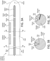
- FIG. 3A, FIG. 3B, and FIG. 3C make up FIG. 3 , which illustrates a first example implementation of a vestibular electrode array 140 with an optical fiber bundle 220 coupled thereto.
- FIG. 3A illustrates a side view of the vestibular electrode array 140.
- FIG. 3B illustrates a cross-section view of the vestibular electrode array 140 taken along line B-B of FIG. 3A.
- FIG. 3C illustrates a cross-section view of the vestibular electrode array 140 taken along line C-C of FIG. 3A .
- the vestibular electrode array 140 includes an elongate carrier 142 that is configured to be implanted proximate a vestibular organ of a recipient.
- the illustrated vestibular electrode array 140 includes at least one vestibular electrode 144 coupled to the elongate carrier 142.
- an optical fiber bundle 220 of one or more optical fibers 222 is coupled to the elongate carrier 142 such that implantation of the elongate carrier 142 can be monitored via the optical fiber bundle 220.
- the illustrated elongate carrier 142 defines a groove 350 at least partially along a side of the elongate carrier 142.
- the groove 350 can be configured to receive the optical fiber bundle 220.
- the groove 350 can be sized and shaped to permit the optical fiber bundle 220 to be disposed in the groove 350 for a distance without the optical fiber bundle 220 extending past a maximum diameter of the vestibular electrode array 140.
- at least a portion of the optical fiber bundle 220 can extend past the maximum diameter of the elongate carrier 142.
- the elongate carrier 142 can be configured to retain the optical fiber bundle 220 in the groove 350.
- the elongate carrier 142 can be so configured by defining the groove 350 such that an interference fit exists between the groove 350 and the optical fiber bundle 220.
- the elongate carrier 142 comprises one or more spans 302 over the groove 350.
- the one or more spans 302 can be configured to retain the optical fiber bundle 220 in the groove 350).
- a span 302 can be a portion of material extending over the groove 350 and defining an opening underneath the span 302 through which the optical fiber bundle 220 can pass.
- the spans 302 extend completely over the groove 350 in certain sections along the elongate carrier 142.
- the spans 302 can be cantilevered over the groove 350 such that the spans 302 partially overhang the groove 350 to retain the optical fiber bundle 220 in the groove 350 but that can be bent to permit the optical fiber bundle 220 to be inserted into or removed from the groove 350.
- the fit between the optical fiber bundle 220 and the opening formed by the groove 350 and the spans 302 can retain the optical fiber bundle 220 in place during implantation such that the optical fiber bundle 220 can be used to visualize implantation.
- the illustrated vestibular electrode array 140 includes one or more wires 352.
- the distal ends of the wires 352 can be coupled to a vestibular electrode 144 and the proximal ends of the wires 352 can couple to the vestibular stimulator 110, such that stimulation signals can be transmitted along the wires 352 to cause stimulation via the vestibular electrodes 144.
- Other signals can be transmitted, such as sensing signals.
- the illustrated vestibular electrode array 140 further includes a catch 314.
- the catch 314 can be a feature of the elongate carrier 142 with which the stylet 190 can interact.
- the catch 314 can be configured to receive a stylet 190 to guide the elongate carrier 142 during insertion of the elongate carrier 142.
- the catch 314 can be so configured by, for example, being sized and shaped to receive the stylet within the catch 314.
- the stylet 190 is configured to be irremovably coupled with the catch 314 (e.g., the stylet 190 cannot be removed without causing damage to the stylet 190 or the elongate carrier 142).
- the stylet 190 can be glued into the catch 314 or embedded within the material forming the catch 314 during manufacture of the elongate carrier 142.
- the stylet 190 can be configured to be removable from the catch 314 (e.g., the stylet 190 can be removed without causing substantial damage to the stylet 190 or the elongate carrier 142).
- there can be a threaded connection between the stylet 190 and the catch 314 such that the stylet 190 can be removed by unscrewing the stylet 190 from the catch 314.
- the stylet 190 can be glued into the catch 314 with a dissolvable adhesive. The stylet 190 can be removed via the application of a solution to dissolve the adhesive.
- One or more of the components of the vestibular electrode array 140 can be radiopaque to facilitate visualization of the vestibular electrode array 140.
- the vestibular electrode array 140 further includes a marker 312.
- the marker 312 can be radiopaque.
- FIG. 3 is an example.
- FIG. 4 Another example implementation is shown in FIG. 4 .
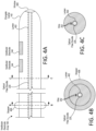
- FIG. 4A, FIG. 4B, and FIG. 4C make up FIG. 4 , which illustrates a second example implementation of a vestibular electrode array 140 with an optical fiber bundle 220 disposed in a lumen 402 of the elongate carrier 142.
- FIG. 4A illustrates a side view of the vestibular electrode array 140.
- FIG. 4B illustrates a cross-section view of the vestibular electrode array 140 taken along line B-B of FIG. 4A.
- FIG. 4C illustrates a cross-section view of the vestibular electrode array 140 taken along line C-C of FIG. 4A .
- the lumen 402 can extend at least partially along the length of the elongate carrier 142 and be sized and shaped to accommodate the optical fiber bundle 220 being disposed therein.
- the optical fiber bundle 220 can be removably or irremovably disposed therein.
- a distal portion of the lumen 402 can terminate at a window 404.
- the window 404 can be an optically transparent region.
- the optical fiber bundle 220 can have a distal end disposed proximate the window 404 such that at least some of the light transmitted via the optical fiber bundle 220 can pass through the window to permit visualization of an area proximate the window.
- the window 404 hermetically seals the distal end of the lumen 402.
- the window 404 is a discrete component from the elongate carrier 142. In other examples, the window 404 can be a portion of the elongate carrier 142 that is optically transparent. In some examples, the window 404 is more optically transparent than the elongate carrier 142. In some examples, the window 404 can be configured as a lens.
- the vestibular electrode array 140 can include a stopper 406.
- the stopper 406 can be a component coupled to the elongate carrier 142 at a location and being configured to resist the elongate carrier 142 being advanced more than a predetermined distance.
- the stopper 406 can be formed as a buildup of material.
- the stopper 406 is an annular collar disposed around a location of the elongate carrier 142.
- the stopper 406 can be sized such that the stopper 406 cannot extend through a particular portion of a recipient's anatomy, such as the recipient's oval window, the recipient's round window, a cochleostomy opening, or an opening in the recipient's stapes.
- the stopper 406 can be coupled with the elongate carrier 142 (e.g., through a friction fit) such that if movement of the stopper 406 is blocked, then movement of the elongate carrier 142 is resisted. Thus, the stopper 406 can resist or prevent the elongate carrier 142 from extending further than a predetermined distance. In some examples, the stopper 406 is a separate component from the elongate carrier and can be disposed in a configurable position along the elongate carrier 142.
- FIG. 5 An example method that can use one or more of the components described above is shown in FIG. 5 .
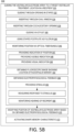
- FIG. 5A and FIG. 5B make up FIG. 5 , which illustrates an example method 500 for implanting a vestibular electrode array and stimulating with the array.
- the method 500 can include operation 510.
- Operation 510 includes making components available for use.
- the operation 510 can include making a vestibular electrode array 140 available for use.
- the operation 510 can include making a vestibular electrode array 140 available for use that has a stylet 190 pre-installed.
- the operation 510 can include making a vestibular electrode array 140 available for use that has an optical fiber bundle 220 pre-installed.
- Making the vestibular electrode array 140 available for use can include making a vestibular electrode array 140 available for use that has an elongate carrier 142 constructed from an optical fiber bundle 220 and having vestibular electrodes 144 coupled to the optical fiber bundle 220.
- the operation 510 can include making a stylet 190 having a straight portion 292 proximate a distal end of the stylet 190 available for use.
- the operation 510 can include making a stylet 190 having a curved portion 294 proximate a distal end of the stylet 190 available for use.
- the operation 510 can include installing or coupling one or more components with respect to each other.
- the operation 510 can include coupling the stylet 190 with the vestibular electrode array 140 (e.g., by coupling the stylet 190 with the catch 314).
- the stylet 190 is removably inserted into the catch 314 of the vestibular electrode array 140.
- the operation 510 can include coupling the optical fiber bundle 220 with the vestibular electrode array 140, such as by placing the optical fiber bundle 220 at least partially within the groove 350 (e.g., and securing the optical fiber bundle 220 with the spans 302) or the lumen 402 depending on the configuration of the vestibular electrode array 140.
- the flow of the method 500 can move to operation 520.
- Operation 520 can include preparing recipient tissue.
- the operation 520 can include sterilizing tissue of the recipient and surgically accessing an implantation area in the recipient.
- the clinician can form one or more incisions in tissue proximate a location where the vestibular stimulation system 100 is to be implanted and remove tissue to expose an implantation area.
- the opening formed by one or more incisions can be sized and shaped to allow for the performance of operations described herein to be performed through the opening.
- surgically accessing the implantation area includes performing a mastoidectomy or a cochleostomy.
- the operation can further include forming or enlarging a posterior tympanotomy, which can include exposing the oval window, such as by superiorly enlarging the posterior tympanotomy.
- surgically accessing the implantation area includes identifying the target vestibular treatment location 10.
- a pocket or a bone bed can be formed for the vestibular stimulator 110 to be disposed in.
- Operation 520 can include operation 522 and 524.
- Operation 522 includes forming an opening in a stapes of the recipient.
- the opening can be formed in a footplate of the stapes, such as by using a surgical drill.
- Operation 524 includes forming an opening proximate the oval window of a recipient.
- the operation 524 includes removing the stapes of the recipient and forming the opening in the oval window.
- an opening is formed through the anulus of the oval window beside the stapes footplate.
- Operation 530 includes guiding the vestibular electrode array 140 to a target vestibular treatment location 10 in the recipient.
- the guiding can be performed in whole in or part by a human clinician.
- the guiding can be performed in whole or in part via a robotic positioner 210 or a micropositioner 212, such as by moving the vestibular electrode array with the robotic positioner 210 or the micropositioner 212.
- operation 530 can include a variety of operations.
- Operation 532 can include guiding a component through an opening in the stapes footplate.
- the method 500 can include forming an opening in the stapes footplate of the recipient.
- a portion of the vestibular electrode array 140 can be guided through the opening in the stapes.
- additional components are also guided through the opening, such as the stylet 190 and the optical fiber bundle 220.
- Operation 534 can include guiding a component through an opening in the oval window.
- the method can include forming an opening in the recipient's oval window.
- a portion of the vestibular electrode array 140 can be guided through the opening in the oval window.
- additional components are also guided through the opening, such as the stylet 190 and the optical fiber bundle 220.
- Operation 536 can include guiding a component through a cochleostomy opening.
- the method can include performing a cochleostomy.
- a portion of the vestibular electrode array 140 can be guided through the opening formed by the cochleostomy.
- additional components are also guided through the opening, such as the stylet 190 and the optical fiber bundle 220.
- Operation 540 can include guiding via a stylet 190.
- guiding the vestibular electrode array 140 to the target vestibular treatment location 10 in the recipient can include moving a proximal end of the stylet 190 (e.g., advancing, retracting, or tilting the proximal end) to control a depth of the vestibular electrode array 140 and an angle of a tip of the vestibular electrode array 140.
- the operation 540 can include twisting the stylet 190 substantially along the stylet's long axis. Twisting the curved stylet 190 can cause rotation of the distal tip of the stylet 190, which can induce movement in a plane substantially perpendicular to the long axis. That movement can provide fine control of the position of the tip of the vestibular electrode array 140.
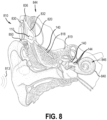
- An example of twisting a curved stylet 190 is shown in FIG. 6 .
- FIG. 6 illustrates an example view of a vestibular electrode array 140 being advanced to a target vestibular treatment location 10 using a stylet 190 having a curved portion at a distal end of the stylet. As illustrated, rotation of the stylet 190 causes the distal portion of the vestibular electrode array 140 to rotate into position at the target vestibular treatment location 10. An alternate insertion location through a cochleostomy opening is further illustrated as an arrow.
Landscapes
- Health & Medical Sciences (AREA)
- Life Sciences & Earth Sciences (AREA)
- Engineering & Computer Science (AREA)
- Public Health (AREA)
- General Health & Medical Sciences (AREA)
- Biomedical Technology (AREA)
- Veterinary Medicine (AREA)
- Animal Behavior & Ethology (AREA)
- Surgery (AREA)
- Heart & Thoracic Surgery (AREA)
- Nuclear Medicine, Radiotherapy & Molecular Imaging (AREA)
- Audiology, Speech & Language Pathology (AREA)
- Molecular Biology (AREA)
- Medical Informatics (AREA)
- Physics & Mathematics (AREA)
- Otolaryngology (AREA)
- Radiology & Medical Imaging (AREA)
- Robotics (AREA)
- Acoustics & Sound (AREA)
- Multimedia (AREA)
- Biophysics (AREA)
- Pathology (AREA)
- Cardiology (AREA)
- Electrotherapy Devices (AREA)
Claims (15)
- Vorrichtung, die umfasst:einen länglichen Träger (142), der zum Implantieren in der Nähe eines vestibulären Organs eines Empfängers ausgeführt ist;wenigstens eine vestibuläre Elektrode (144), die mit dem länglichen Träger (142) gekoppelt ist; sowieein Lichtleitfaser-Bündel (220) aus einer oder mehreren Lichtleitfaser/n (222),dadurch gekennzeichnet, dassdas Lichtleitfaser-Bündel (220) so mit dem länglichen Träger (142) gekoppelt ist, dass Implantation des länglichen Trägers (142) über das Lichtleitfaser-Bündel (220) überwacht werden kann; unddas Lichtleitfaser-Bündel (220) von dem länglichen Träger (142) gelöst werden kann.
- Vorrichtung nach Anspruch 1, wobei der längliche Träger (142) eine Nut (350) wenigstens teilweise entlang einer Seite des länglichen Trägers (142) aufweist.
- Vorrichtung nach Anspruch 2, wobei der längliche Träger (142) ein oder mehrere Joch/e (302) über der Nut (350) umfasst; und
wobei das eine oder die mehreren Joch/e (302) so ausgeführt ist/sind, dass sie das Lichtleitfaser-Bündel (220) in der Nut (350) hält/halten. - Vorrichtung nach einem der Ansprüche 1, 2 oder 3, wobei ein oder mehrere Komponente/n der Vorrichtung strahlenundurchlässig ist/sind.
- Vorrichtung nach einem der Ansprüche 1, 2 oder 3, wobei der längliche Träger (142) einen Anschlag (314) aufweist, der zum Aufnehmen einer Sonde (190) ausgeführt ist, mit der der längliche Träger (142) bei Einführung des länglichen Trägers (142) geführt wird.
- Bausatz, der umfasst:einen implantierbaren vestibulären Stimulator (110) mit einem biokompatiblen Gehäuse (111); sowiedie Vorrichtung nach Anspruch 5, wobei der längliche Träger (142) zum Koppeln mit dem implantierbaren vestibulären Stimulator (110) ausgeführt oder mit ihm gekoppelt ist;wobei die Sonde eine erste Sonde (190) mit einem geraden Abschnitt nahe an einem ersten distalen Sonden-Ende der ersten Sonde oder/und eine zweite Sonde (190) mit einem gekrümmten Abschnitt nahe an einem zweiten distalen Sonden-Ende der zweiten Sonde ist.
- Bausatz nach Anspruch 6, das des Weiteren eine Befestigungseinrichtung (194) umfasst, die zum Befestigen der ersten Sonde (190) oder der zweiten Sonde (190) an einem Schädel eines Empfängers ausgeführt ist.
- Bausatz nach einem der Ansprüche 6 oder 7, der des Weiteren umfasst:
einen Puffer (406), der mit dem länglichen Träger (142) an einer Position gekoppelt ist, durch die verhindert wird, dass der längliche Träger (142) um mehr als eine vorgegebene Strecke vorgerückt wird. - Bausatz nach einem der Ansprüche 6, 7 oder 8,wobei der Bausatz (200) sowohl die erste Sonde (190) als auch die zweite Sonde (190) einschließt;der Bausatz (200) des Weiteren einen Positionierroboter (210) einschließt;der Bausatz (200) des Weiteren einen Mikropositionierer (212) einschließt;der Bausatz (200) des Weiteren einen Dichtstoff (214) oder einen Stopfen (216) einschließt, der zum Abdichten einer Öffnung eines Lumens (402) des länglichen Trägers (142) ausgeführt ist;wobei die erste Sonde (190) oder die zweite Sonde (190) aus Metall, Glas oder Polymer aufgebaut ist;wobei die erste Sonde (190) oder die zweite Sonde (190) von einem Anschlag (314) des länglichen Trägers (142) gelöst werden kann;wobei die erste Sonde (190) oder die zweite Sonde (190) steif ist;wobei die erste Sonde (190) oder die zweite Sonde (190) verformbar ist;wobei die erste Sonde (190), die zweite Sonde (190) oder der längliche Träger (142) Formgedächtnis-Eigenschaften aufweist;wobei die erste Sonde (190), die zweite Sonde (190) oder der längliche Träger (142) Formgedächtnis-Eigenschaften aufweist, die durch Temperatur aktiviert werden;wobei die erste Sonde (190), die zweite Sonde (190) oder der längliche Träger (142) Formgedächtnis-Eigenschaften aufweist, die durch elektrischen Strom aktiviert werden; oderwobei die erste Sonde (190), die zweite Sonde (190) oder der längliche Träger (142) ein Polymer mit Formgedächtnis-Eigenschaften aufweist, die durch elektrischen Strom aktiviert werden.
- Bausatz nach einem der Ansprüche 6 - 9, wobei der Bausatz so ausgeführt ist, dass er über die Sonde die vestibuläre Elektrodenanordnung (140) zu der vestibulären Behandlungs-Zielposition (10) in dem Empfänger führt und dabei eine Steigbügel-Fußplatte des Empfängers als einen Drehpunkt einsetzt (544), der Feinsteuerung eines distalen Abschnitts der Sonde (190) ermöglicht.
- Bausatz nach Anspruch 10,
wobei das Führen (530) einschließt:Beziehen (560) elektrophysiologischer Rückmeldung bezüglich einer Position der vestibulären Elektrodenanordnung (140); sowieModifizieren der Position der vestibulären Elektrodenanordnung auf Basis der bezogenen elektrophysiologischen Rückmeldung. - Bausatz nach Anspruch 11, wobei Führen (530) der vestibulären Elektrodenanordnung (140) zu der vestibulären Behandlungs-Zielposition (10) in dem Empfänger des Weiteren einschließt:
Beziehen (552) eines Röntgenbildes, das eine Position eines radioopaken Markers (312) der vestibulären Elektrodenanordnung (140) relativ zu der vestibulären Behandlungs-Zielposition (10) zeigt. - Bausatz nach Anspruch 11 oder 12, wobei Beziehen der elektrophysiologischen Rückmeldung einschließt:
Erzeugen (562) eines Stimulus unter Verwendung wenigstens einer vestibulären Elektrode (144) der vestibulären Elektrodenanordnung (140); sowie Messen (564) einer Nerven- oder Muskelreaktion auf den erzeugten Stimulus. - Bausatz nach einem der Ansprüche 11 - 13, der des Weiteren Einrichtungen umfasst zum:Überwachen (566) von Hören des Empfängers unter Einsatz von Elektrocochleographie, und/oderErzeugen (547) einer sichtbaren Anzeige oder einer hörbaren Anzeige der Position, und/oderErzeugen (548) der hörbaren Anzeige der Position über eine Änderung von Höhe eines Tons.
- Bausatz nach einem der Ansprüche 11 - 14,
wobei das Führen (530) wenigstens teilweise von einem Positionierroboter (210) durchgeführt wird.
Applications Claiming Priority (2)
| Application Number | Priority Date | Filing Date | Title |
|---|---|---|---|
| US202063056159P | 2020-07-24 | 2020-07-24 | |
| PCT/IB2021/054978 WO2022018530A1 (en) | 2020-07-24 | 2021-06-07 | Vestibular electrode array |
Publications (3)
| Publication Number | Publication Date |
|---|---|
| EP4185371A1 EP4185371A1 (de) | 2023-05-31 |
| EP4185371A4 EP4185371A4 (de) | 2024-04-03 |
| EP4185371B1 true EP4185371B1 (de) | 2025-07-09 |
Family
ID=79728573
Family Applications (1)
| Application Number | Title | Priority Date | Filing Date |
|---|---|---|---|
| EP21846277.8A Active EP4185371B1 (de) | 2020-07-24 | 2021-06-07 | Vestibuläre elektrodenanordnung |
Country Status (3)
| Country | Link |
|---|---|
| US (2) | US20230263582A1 (de) |
| EP (1) | EP4185371B1 (de) |
| WO (1) | WO2022018530A1 (de) |
Families Citing this family (4)
| Publication number | Priority date | Publication date | Assignee | Title |
|---|---|---|---|---|
| WO2024231794A1 (en) * | 2023-05-09 | 2024-11-14 | Cochlear Limited | Medical device insertion with contour mapping |
| WO2024261622A1 (en) * | 2023-06-20 | 2024-12-26 | Cochlear Limited | Hearing preservation vestibular stimulation |
| WO2025235392A1 (en) * | 2024-05-09 | 2025-11-13 | Med-El Elektromedizinische Gerate Gmbh | Stapes fixation flange for inner ear electrodes |
| WO2026053066A1 (en) * | 2024-09-03 | 2026-03-12 | Cochlear Limited | Variable shape memory element |
Family Cites Families (20)
| Publication number | Priority date | Publication date | Assignee | Title |
|---|---|---|---|---|
| US5645585A (en) * | 1996-03-15 | 1997-07-08 | Cochlear Ltd. | Cochlear electrode implant assembly with positioning system therefor |
| US5888577A (en) * | 1997-06-30 | 1999-03-30 | Procath Corporation | Method for forming an electrophysiology catheter |
| US6968238B1 (en) * | 1998-08-26 | 2005-11-22 | Kuzma Janusz A | Method for inserting cochlear electrode and insertion tool for use therewith |
| WO2002028473A1 (en) * | 2000-10-04 | 2002-04-11 | Cochlear Limited | Cochlear implant electrode array |
| US20060235500A1 (en) * | 2002-06-28 | 2006-10-19 | Peter Gibson | Optic fibre device |
| US7137946B2 (en) * | 2003-12-11 | 2006-11-21 | Otologics Llc | Electrophysiological measurement method and system for positioning an implantable, hearing instrument transducer |
| US7488341B2 (en) * | 2005-09-14 | 2009-02-10 | Massachusetts Eye & Ear Infirmary | Method for optical stimulation of the vestibular system |
| US7883536B1 (en) * | 2007-01-19 | 2011-02-08 | Lockheed Martin Corporation | Hybrid optical-electrical probes |
| US20140324138A1 (en) * | 2007-05-09 | 2014-10-30 | Massachusetts Institute Of Technology | Wirelessly-powered illumination of biological tissue |
| US8594799B2 (en) * | 2008-10-31 | 2013-11-26 | Advanced Bionics | Cochlear electrode insertion |
| EP2493554B1 (de) * | 2009-10-30 | 2018-09-12 | Advanced Bionics, LLC | Steuerbarer mandrin |
| WO2011053766A1 (en) * | 2009-10-30 | 2011-05-05 | Advanced Bionics, Llc | Steerable stylet |
| WO2014105059A1 (en) * | 2012-12-28 | 2014-07-03 | Advanced Bionics Ag | Tip elements for cochlear implants |
| WO2015030739A1 (en) * | 2013-08-27 | 2015-03-05 | Advanced Bionics Ag | Implantable leads with flag extensions |
| US8843217B1 (en) | 2013-09-13 | 2014-09-23 | Lockheed Martin Corporation | Combined vestibular and cochlear implant and method |
| WO2017182682A1 (es) * | 2016-04-21 | 2017-10-26 | Universidad De Las Palmas De Gran Canaria | Método para la detección automática de fold-over en implantes de porta-electrodos mediante matriz de potenciales |
| GB201613982D0 (en) * | 2016-08-16 | 2016-09-28 | Univ Oxford Innovation Ltd | Assessing suitability of implanted target in deep brain stimulation (DBS) |
| WO2018200450A1 (en) * | 2017-04-24 | 2018-11-01 | Vanderbilt University | Methods and systems for optimizing selection and placement of cochlear implant electrode arrays using patient-specific cochlear information and applications of same |
| US11235150B2 (en) * | 2018-12-17 | 2022-02-01 | Advanced Bionics Ag | Cochlear implant leads and methods of making the same |
| US12296174B2 (en) * | 2019-08-26 | 2025-05-13 | Cochlear Limited | Vestibular stimulation control |
-
2021
- 2021-06-07 US US18/005,102 patent/US20230263582A1/en active Pending
- 2021-06-07 WO PCT/IB2021/054978 patent/WO2022018530A1/en not_active Ceased
- 2021-06-07 EP EP21846277.8A patent/EP4185371B1/de active Active
-
2023
- 2023-06-22 US US18/339,496 patent/US20230338097A1/en active Pending
Also Published As
| Publication number | Publication date |
|---|---|
| US20230263582A1 (en) | 2023-08-24 |
| EP4185371A1 (de) | 2023-05-31 |
| WO2022018530A1 (en) | 2022-01-27 |
| EP4185371A4 (de) | 2024-04-03 |
| US20230338097A1 (en) | 2023-10-26 |
Similar Documents
| Publication | Publication Date | Title |
|---|---|---|
| EP4185371B1 (de) | Vestibuläre elektrodenanordnung | |
| US12171999B2 (en) | Vestibular stimulation device | |
| US12465755B2 (en) | Neural stimulator with flying lead electrode | |
| US20140350640A1 (en) | Implantable Medical Device and Tool Sensors | |
| US20150320550A1 (en) | Tip elements for cochlear implants | |
| EP3519040B1 (de) | Auf wahrnehmungsveränderung basierende anpassung in hörprothesen | |
| JP2004509727A (ja) | 移植用蝸牛電極列 | |
| US12186560B2 (en) | Vestibular stimulation prosthesis | |
| US10034797B2 (en) | Cochlear implant electrode insertion bridge | |
| US20220273952A1 (en) | Vestibular stimulation control | |
| CN116157180A (zh) | 具有预成形组件的医用植入物 | |
| US20230398365A1 (en) | System and method for electrode implantation | |
| EP4291296B1 (de) | Integrierte schlauchhülle | |
| US20260054069A1 (en) | Evoked biological response proximity analysis | |
| US20230355962A1 (en) | Advanced surgically implantable technologies | |
| WO2025062298A1 (en) | Hearing preserving vestibular stimulation | |
| CN117500559A (zh) | 迷走神经刺激 | |
| US20220330978A1 (en) | Stimulation assembly sheath with signal pathway | |
| WO2024261622A1 (en) | Hearing preservation vestibular stimulation | |
| WO2024261590A1 (en) | Vestibuleostomy-based vestibular stimulation | |
| CN107427362A (zh) | 无创前庭刺激和测量电极 | |
| EP4588070A1 (de) | Unbeabsichtigte stimulationsverwaltung |
Legal Events
| Date | Code | Title | Description |
|---|---|---|---|
| STAA | Information on the status of an ep patent application or granted ep patent |
Free format text: STATUS: THE INTERNATIONAL PUBLICATION HAS BEEN MADE |
|
| PUAI | Public reference made under article 153(3) epc to a published international application that has entered the european phase |
Free format text: ORIGINAL CODE: 0009012 |
|
| STAA | Information on the status of an ep patent application or granted ep patent |
Free format text: STATUS: REQUEST FOR EXAMINATION WAS MADE |
|
| 17P | Request for examination filed |
Effective date: 20221212 |
|
| AK | Designated contracting states |
Kind code of ref document: A1 Designated state(s): AL AT BE BG CH CY CZ DE DK EE ES FI FR GB GR HR HU IE IS IT LI LT LU LV MC MK MT NL NO PL PT RO RS SE SI SK SM TR |
|
| DAV | Request for validation of the european patent (deleted) | ||
| DAX | Request for extension of the european patent (deleted) | ||
| A4 | Supplementary search report drawn up and despatched |
Effective date: 20240304 |
|
| RIC1 | Information provided on ipc code assigned before grant |
Ipc: A61N 1/372 20060101ALI20240227BHEP Ipc: A61N 1/375 20060101ALI20240227BHEP Ipc: A61N 1/05 20060101ALI20240227BHEP Ipc: A61N 1/36 20060101AFI20240227BHEP |
|
| GRAP | Despatch of communication of intention to grant a patent |
Free format text: ORIGINAL CODE: EPIDOSNIGR1 |
|
| STAA | Information on the status of an ep patent application or granted ep patent |
Free format text: STATUS: GRANT OF PATENT IS INTENDED |
|
| INTG | Intention to grant announced |
Effective date: 20250217 |
|
| GRAS | Grant fee paid |
Free format text: ORIGINAL CODE: EPIDOSNIGR3 |
|
| GRAA | (expected) grant |
Free format text: ORIGINAL CODE: 0009210 |
|
| STAA | Information on the status of an ep patent application or granted ep patent |
Free format text: STATUS: THE PATENT HAS BEEN GRANTED |
|
| AK | Designated contracting states |
Kind code of ref document: B1 Designated state(s): AL AT BE BG CH CY CZ DE DK EE ES FI FR GB GR HR HU IE IS IT LI LT LU LV MC MK MT NL NO PL PT RO RS SE SI SK SM TR |
|
| P01 | Opt-out of the competence of the unified patent court (upc) registered |
Free format text: CASE NUMBER: APP_26503/2025 Effective date: 20250604 |
|
| REG | Reference to a national code |
Ref country code: GB Ref legal event code: FG4D |
|
| REG | Reference to a national code |
Ref country code: CH Ref legal event code: EP |
|
| REG | Reference to a national code |
Ref country code: IE Ref legal event code: FG4D |
|
| REG | Reference to a national code |
Ref country code: DE Ref legal event code: R096 Ref document number: 602021033946 Country of ref document: DE |
|
| REG | Reference to a national code |
Ref country code: NL Ref legal event code: MP Effective date: 20250709 |
|
| PG25 | Lapsed in a contracting state [announced via postgrant information from national office to epo] |
Ref country code: PT Free format text: LAPSE BECAUSE OF FAILURE TO SUBMIT A TRANSLATION OF THE DESCRIPTION OR TO PAY THE FEE WITHIN THE PRESCRIBED TIME-LIMIT Effective date: 20251110 |
|
| PG25 | Lapsed in a contracting state [announced via postgrant information from national office to epo] |
Ref country code: NL Free format text: LAPSE BECAUSE OF FAILURE TO SUBMIT A TRANSLATION OF THE DESCRIPTION OR TO PAY THE FEE WITHIN THE PRESCRIBED TIME-LIMIT Effective date: 20250709 |
|
| REG | Reference to a national code |
Ref country code: AT Ref legal event code: MK05 Ref document number: 1811306 Country of ref document: AT Kind code of ref document: T Effective date: 20250709 |
|
| PG25 | Lapsed in a contracting state [announced via postgrant information from national office to epo] |
Ref country code: IS Free format text: LAPSE BECAUSE OF FAILURE TO SUBMIT A TRANSLATION OF THE DESCRIPTION OR TO PAY THE FEE WITHIN THE PRESCRIBED TIME-LIMIT Effective date: 20251109 |
|
| PG25 | Lapsed in a contracting state [announced via postgrant information from national office to epo] |
Ref country code: NO Free format text: LAPSE BECAUSE OF FAILURE TO SUBMIT A TRANSLATION OF THE DESCRIPTION OR TO PAY THE FEE WITHIN THE PRESCRIBED TIME-LIMIT Effective date: 20251009 |
|
| REG | Reference to a national code |
Ref country code: LT Ref legal event code: MG9D |
|
| PG25 | Lapsed in a contracting state [announced via postgrant information from national office to epo] |
Ref country code: AT Free format text: LAPSE BECAUSE OF FAILURE TO SUBMIT A TRANSLATION OF THE DESCRIPTION OR TO PAY THE FEE WITHIN THE PRESCRIBED TIME-LIMIT Effective date: 20250709 |
|
| PG25 | Lapsed in a contracting state [announced via postgrant information from national office to epo] |
Ref country code: FI Free format text: LAPSE BECAUSE OF FAILURE TO SUBMIT A TRANSLATION OF THE DESCRIPTION OR TO PAY THE FEE WITHIN THE PRESCRIBED TIME-LIMIT Effective date: 20250709 |
|
| PG25 | Lapsed in a contracting state [announced via postgrant information from national office to epo] |
Ref country code: HR Free format text: LAPSE BECAUSE OF FAILURE TO SUBMIT A TRANSLATION OF THE DESCRIPTION OR TO PAY THE FEE WITHIN THE PRESCRIBED TIME-LIMIT Effective date: 20250709 |
|
| PG25 | Lapsed in a contracting state [announced via postgrant information from national office to epo] |
Ref country code: GR Free format text: LAPSE BECAUSE OF FAILURE TO SUBMIT A TRANSLATION OF THE DESCRIPTION OR TO PAY THE FEE WITHIN THE PRESCRIBED TIME-LIMIT Effective date: 20251010 |
|
| PG25 | Lapsed in a contracting state [announced via postgrant information from national office to epo] |
Ref country code: SE Free format text: LAPSE BECAUSE OF FAILURE TO SUBMIT A TRANSLATION OF THE DESCRIPTION OR TO PAY THE FEE WITHIN THE PRESCRIBED TIME-LIMIT Effective date: 20250709 |
|
| PG25 | Lapsed in a contracting state [announced via postgrant information from national office to epo] |
Ref country code: LV Free format text: LAPSE BECAUSE OF FAILURE TO SUBMIT A TRANSLATION OF THE DESCRIPTION OR TO PAY THE FEE WITHIN THE PRESCRIBED TIME-LIMIT Effective date: 20250709 |
|
| PG25 | Lapsed in a contracting state [announced via postgrant information from national office to epo] |
Ref country code: BG Free format text: LAPSE BECAUSE OF FAILURE TO SUBMIT A TRANSLATION OF THE DESCRIPTION OR TO PAY THE FEE WITHIN THE PRESCRIBED TIME-LIMIT Effective date: 20250709 Ref country code: PL Free format text: LAPSE BECAUSE OF FAILURE TO SUBMIT A TRANSLATION OF THE DESCRIPTION OR TO PAY THE FEE WITHIN THE PRESCRIBED TIME-LIMIT Effective date: 20250709 |
|
| PG25 | Lapsed in a contracting state [announced via postgrant information from national office to epo] |
Ref country code: RS Free format text: LAPSE BECAUSE OF FAILURE TO SUBMIT A TRANSLATION OF THE DESCRIPTION OR TO PAY THE FEE WITHIN THE PRESCRIBED TIME-LIMIT Effective date: 20251009 |
|
| PG25 | Lapsed in a contracting state [announced via postgrant information from national office to epo] |
Ref country code: ES Free format text: LAPSE BECAUSE OF FAILURE TO SUBMIT A TRANSLATION OF THE DESCRIPTION OR TO PAY THE FEE WITHIN THE PRESCRIBED TIME-LIMIT Effective date: 20250709 |
|
| PG25 | Lapsed in a contracting state [announced via postgrant information from national office to epo] |
Ref country code: SM Free format text: LAPSE BECAUSE OF FAILURE TO SUBMIT A TRANSLATION OF THE DESCRIPTION OR TO PAY THE FEE WITHIN THE PRESCRIBED TIME-LIMIT Effective date: 20250709 |
|
| PG25 | Lapsed in a contracting state [announced via postgrant information from national office to epo] |
Ref country code: DK Free format text: LAPSE BECAUSE OF FAILURE TO SUBMIT A TRANSLATION OF THE DESCRIPTION OR TO PAY THE FEE WITHIN THE PRESCRIBED TIME-LIMIT Effective date: 20250709 |
|
| PG25 | Lapsed in a contracting state [announced via postgrant information from national office to epo] |
Ref country code: IT Free format text: LAPSE BECAUSE OF FAILURE TO SUBMIT A TRANSLATION OF THE DESCRIPTION OR TO PAY THE FEE WITHIN THE PRESCRIBED TIME-LIMIT Effective date: 20250709 |