EP4184797B1 - Signalverarbeitungsverfahren und -vorrichtung - Google Patents
Signalverarbeitungsverfahren und -vorrichtung Download PDFInfo
- Publication number
- EP4184797B1 EP4184797B1 EP20948325.4A EP20948325A EP4184797B1 EP 4184797 B1 EP4184797 B1 EP 4184797B1 EP 20948325 A EP20948325 A EP 20948325A EP 4184797 B1 EP4184797 B1 EP 4184797B1
- Authority
- EP
- European Patent Office
- Prior art keywords
- signals
- range
- data
- fft
- processing
- Prior art date
- Legal status (The legal status is an assumption and is not a legal conclusion. Google has not performed a legal analysis and makes no representation as to the accuracy of the status listed.)
- Active
Links
Images


Classifications
-
- G—PHYSICS
- G01—MEASURING; TESTING
- G01S—RADIO DIRECTION-FINDING; RADIO NAVIGATION; DETERMINING DISTANCE OR VELOCITY BY USE OF RADIO WAVES; LOCATING OR PRESENCE-DETECTING BY USE OF THE REFLECTION OR RERADIATION OF RADIO WAVES; ANALOGOUS ARRANGEMENTS USING OTHER WAVES
- G01S13/00—Systems using the reflection or reradiation of radio waves, e.g. radar systems; Analogous systems using reflection or reradiation of waves whose nature or wavelength is irrelevant or unspecified
- G01S13/02—Systems using reflection of radio waves, e.g. primary radar systems; Analogous systems
- G01S13/50—Systems of measurement based on relative movement of target
- G01S13/58—Velocity or trajectory determination systems; Sense-of-movement determination systems
-
- G—PHYSICS
- G01—MEASURING; TESTING
- G01S—RADIO DIRECTION-FINDING; RADIO NAVIGATION; DETERMINING DISTANCE OR VELOCITY BY USE OF RADIO WAVES; LOCATING OR PRESENCE-DETECTING BY USE OF THE REFLECTION OR RERADIATION OF RADIO WAVES; ANALOGOUS ARRANGEMENTS USING OTHER WAVES
- G01S7/00—Details of systems according to groups G01S13/00, G01S15/00, G01S17/00
- G01S7/02—Details of systems according to groups G01S13/00, G01S15/00, G01S17/00 of systems according to group G01S13/00
- G01S7/28—Details of pulse systems
- G01S7/285—Receivers
- G01S7/288—Coherent receivers
- G01S7/2883—Coherent receivers using FFT processing
-
- G—PHYSICS
- G01—MEASURING; TESTING
- G01S—RADIO DIRECTION-FINDING; RADIO NAVIGATION; DETERMINING DISTANCE OR VELOCITY BY USE OF RADIO WAVES; LOCATING OR PRESENCE-DETECTING BY USE OF THE REFLECTION OR RERADIATION OF RADIO WAVES; ANALOGOUS ARRANGEMENTS USING OTHER WAVES
- G01S13/00—Systems using the reflection or reradiation of radio waves, e.g. radar systems; Analogous systems using reflection or reradiation of waves whose nature or wavelength is irrelevant or unspecified
- G01S13/02—Systems using reflection of radio waves, e.g. primary radar systems; Analogous systems
- G01S13/06—Systems determining position data of a target
- G01S13/08—Systems for measuring distance only
- G01S13/10—Systems for measuring distance only using transmission of interrupted, pulse modulated waves
- G01S13/26—Systems for measuring distance only using transmission of interrupted, pulse modulated waves wherein the transmitted pulses use a frequency- or phase-modulated carrier wave
-
- G—PHYSICS
- G01—MEASURING; TESTING
- G01S—RADIO DIRECTION-FINDING; RADIO NAVIGATION; DETERMINING DISTANCE OR VELOCITY BY USE OF RADIO WAVES; LOCATING OR PRESENCE-DETECTING BY USE OF THE REFLECTION OR RERADIATION OF RADIO WAVES; ANALOGOUS ARRANGEMENTS USING OTHER WAVES
- G01S13/00—Systems using the reflection or reradiation of radio waves, e.g. radar systems; Analogous systems using reflection or reradiation of waves whose nature or wavelength is irrelevant or unspecified
- G01S13/02—Systems using reflection of radio waves, e.g. primary radar systems; Analogous systems
- G01S13/06—Systems determining position data of a target
- G01S13/08—Systems for measuring distance only
- G01S13/32—Systems for measuring distance only using transmission of continuous waves, whether amplitude-, frequency-, or phase-modulated, or unmodulated
- G01S13/34—Systems for measuring distance only using transmission of continuous waves, whether amplitude-, frequency-, or phase-modulated, or unmodulated using transmission of continuous, frequency-modulated waves while heterodyning the received signal, or a signal derived therefrom, with a locally-generated signal related to the contemporaneously transmitted signal
- G01S13/343—Systems for measuring distance only using transmission of continuous waves, whether amplitude-, frequency-, or phase-modulated, or unmodulated using transmission of continuous, frequency-modulated waves while heterodyning the received signal, or a signal derived therefrom, with a locally-generated signal related to the contemporaneously transmitted signal using sawtooth modulation
-
- G—PHYSICS
- G01—MEASURING; TESTING
- G01S—RADIO DIRECTION-FINDING; RADIO NAVIGATION; DETERMINING DISTANCE OR VELOCITY BY USE OF RADIO WAVES; LOCATING OR PRESENCE-DETECTING BY USE OF THE REFLECTION OR RERADIATION OF RADIO WAVES; ANALOGOUS ARRANGEMENTS USING OTHER WAVES
- G01S13/00—Systems using the reflection or reradiation of radio waves, e.g. radar systems; Analogous systems using reflection or reradiation of waves whose nature or wavelength is irrelevant or unspecified
- G01S13/02—Systems using reflection of radio waves, e.g. primary radar systems; Analogous systems
- G01S13/06—Systems determining position data of a target
- G01S13/42—Simultaneous measurement of distance and other co-ordinates
-
- G—PHYSICS
- G01—MEASURING; TESTING
- G01S—RADIO DIRECTION-FINDING; RADIO NAVIGATION; DETERMINING DISTANCE OR VELOCITY BY USE OF RADIO WAVES; LOCATING OR PRESENCE-DETECTING BY USE OF THE REFLECTION OR RERADIATION OF RADIO WAVES; ANALOGOUS ARRANGEMENTS USING OTHER WAVES
- G01S13/00—Systems using the reflection or reradiation of radio waves, e.g. radar systems; Analogous systems using reflection or reradiation of waves whose nature or wavelength is irrelevant or unspecified
- G01S13/02—Systems using reflection of radio waves, e.g. primary radar systems; Analogous systems
- G01S13/50—Systems of measurement based on relative movement of target
- G01S13/58—Velocity or trajectory determination systems; Sense-of-movement determination systems
- G01S13/581—Velocity or trajectory determination systems; Sense-of-movement determination systems using transmission of interrupted pulse modulated waves and based upon the Doppler effect resulting from movement of targets
- G01S13/582—Velocity or trajectory determination systems; Sense-of-movement determination systems using transmission of interrupted pulse modulated waves and based upon the Doppler effect resulting from movement of targets adapted for simultaneous range and velocity measurements
-
- G—PHYSICS
- G01—MEASURING; TESTING
- G01S—RADIO DIRECTION-FINDING; RADIO NAVIGATION; DETERMINING DISTANCE OR VELOCITY BY USE OF RADIO WAVES; LOCATING OR PRESENCE-DETECTING BY USE OF THE REFLECTION OR RERADIATION OF RADIO WAVES; ANALOGOUS ARRANGEMENTS USING OTHER WAVES
- G01S13/00—Systems using the reflection or reradiation of radio waves, e.g. radar systems; Analogous systems using reflection or reradiation of waves whose nature or wavelength is irrelevant or unspecified
- G01S13/02—Systems using reflection of radio waves, e.g. primary radar systems; Analogous systems
- G01S13/50—Systems of measurement based on relative movement of target
- G01S13/58—Velocity or trajectory determination systems; Sense-of-movement determination systems
- G01S13/583—Velocity or trajectory determination systems; Sense-of-movement determination systems using transmission of continuous unmodulated waves, amplitude-, frequency-, or phase-modulated waves and based upon the Doppler effect resulting from movement of targets
- G01S13/584—Velocity or trajectory determination systems; Sense-of-movement determination systems using transmission of continuous unmodulated waves, amplitude-, frequency-, or phase-modulated waves and based upon the Doppler effect resulting from movement of targets adapted for simultaneous range and velocity measurements
-
- G—PHYSICS
- G01—MEASURING; TESTING
- G01S—RADIO DIRECTION-FINDING; RADIO NAVIGATION; DETERMINING DISTANCE OR VELOCITY BY USE OF RADIO WAVES; LOCATING OR PRESENCE-DETECTING BY USE OF THE REFLECTION OR RERADIATION OF RADIO WAVES; ANALOGOUS ARRANGEMENTS USING OTHER WAVES
- G01S7/00—Details of systems according to groups G01S13/00, G01S15/00, G01S17/00
- G01S7/02—Details of systems according to groups G01S13/00, G01S15/00, G01S17/00 of systems according to group G01S13/00
- G01S7/35—Details of non-pulse systems
- G01S7/352—Receivers
- G01S7/356—Receivers involving particularities of FFT processing
Definitions
- This application relates to the field of communication technologies, and in particular, to a signal processing method and apparatus.
- Radar detection is widely applied to various fields, for example, an advanced driver assistant system (advanced driver assistant system, ADAS), an unmanned driving field, or the like.
- ADAS advanced driver assistant system
- ADAS advanced driver assistant system
- a higher range resolution and a higher angle resolution are required for the radar detection.
- a radar may improve the range resolution by transmitting a larger bandwidth, and achieve the higher angle resolution by setting more multiple input multiple output (multiple input multiple output, MIMO) arrays.
- a radar provided with the MIMO array may be referred to as a MIMO radar.
- the MIMO radar may support a large quantity of transmit antennas to transmit signals in turn.
- a relative pulse repetition interval (pulse repetition interval, PRI) of a single antenna is long, and a detection range of the MIMO radar for a moving velocity of a target is reduced.
- the moving velocity of the target beyond a maximum velocity detection range of the MIMO radar is aliased into the detection range, resulting in velocity ambiguity of the target.
- a single input multiple output (single input multiple output, SIMO) + MIMO radar detection mechanism is further proposed in the industry.
- the radar may work in either MIMO mode or SIMO mode.
- the radar may detect the target through the SIMO mode and the MIMO mode respectively, and based on different PRI intervals of the SIMO mode and the MIMO mode, perform velocity matching ambiguity resolution processing on signals obtained in the MIMO mode by using signals obtained in the SIMO mode.
- precision of velocity matching ambiguity resolution processing performed on signals obtained in the SIMO + MIMO mode still faces a challenge.
- This application provides a signal processing method and apparatus, to improve precision of velocity matching ambiguity resolution processing performed on signals in a SIMO + MIMO mode.
- FIG. 1 is a schematic diagram of a radar detection system 100 according to an embodiment of this application.
- the radar detection system 100 may work in a SIMO mode, or may work in a MIMO mode.
- the radar detection system 100 includes a transmitter 110, a receiver 120, and a processing unit 130.
- the transmitter 110 may include Nt transmit antennas, and each transmit antenna corresponds to one transmit channel.
- the receiver 120 includes Nr receive antennas, and each receive antenna corresponds to one receive channel.
- the Nt transmit antennas and the Nr receive antennas may form a MIMO antenna array.
- the radar detection system 100 may transmit a signal to a target by using at least two transmit channels in Nt transmit channels, and receive, by using at least two receive channels in Nr receive channels, an echo signal reflected by the target.
- the radar detection system 100 may transmit a signal to the target by using one of the Nt transmit channels, and receive, by using at least two receive channels among the Nr receive channels, the echo signal reflected by the target.
- the SIMO mode and the MIMO mode may share a same set of transmit antennas and receive antennas (for example, a MIMO antenna array).
- the SIMO mode and the MIMO mode may alternatively respectively use different transmit antennas and different receive antennas. This is not limited in this embodiment of this application.
- quantities of receive channels used by the radar detection system 100 in the SIMO mode and the MIMO mode may be the same or may be different.
- the processing unit 130 may be configured to control the transmitter 110 to send a signal, or control the receiver 120 to receive a signal, and may be further configured to process a to-be-sent signal or a receive signal.
- the processing unit 130 may include a central processing unit (central processor unit, CPU), a field programmable gate array (field programmable gate array, FPGA), or an application-specific integrated circuit (application-specific integrated circuit, ASIC), or may be a processing chip of another type.
- CPU central processor unit
- FPGA field programmable gate array
- ASIC application-specific integrated circuit
- a structure of the radar detection system 100 in FIG. 1 is merely used as an example instead of a limitation.
- a person skilled in the art may understand that the radar detection system 100 may further include more or fewer modules or units.
- the radar detection system 100 may also be referred to as a radar for short.
- the SIMO mode is mainly used for performing velocity matching ambiguity resolution on a detection target in the MIMO mode. Therefore, in the industry, considering a radar update period, a quantity of signals transmitted in the SIMO mode is reduced as much as possible. This results in velocity resolution ⁇ v and velocity measurement precision ⁇ v of a target in the SIMO mode when the velocity ambiguity resolution processing is performed. There is a great difference between the velocity resolution ⁇ v and the velocity measurement precision ⁇ v of the target in the MIMO mode, which affects precision of performing the velocity matching ambiguity resolution processing on signals. To resolve the foregoing problem, the embodiments of this application provide a signal processing method and apparatus, which may improve the precision of performing the velocity matching ambiguity resolution on the signals in a SIMO + MIMO radar detection mechanism.
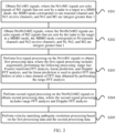
- FIG. 2 is a schematic flowchart of a signal processing method according to an embodiment of this application.
- the method in FIG. 2 is based on the SIMO + MIMO radar detection mechanism, and the method may be performed by the radar 100 in FIG. 1 .
- the method in FIG. 2 includes the following steps.
- Nr1 ⁇ M1 signals where the Nr1 ⁇ M1 signals are echo signals of M1 signals that are sent by a radar to a target in a SIMO mode, the SIMO mode corresponds to one transmit channel and Nr1 receive channels, and Nr1 and M1 are integers greater than 1.
- the radar sends and receives signals by using one transmit channel and Nr1 receive channels. Specifically, the radar sends M1 signals through one transmit channel. After the M1 signals are reflected by the target, the Nr1 receive channels receive the Nr1 ⁇ M1 signals in total.
- the radar sends and receives signals by using Nt transmit channels and Nr2 receive channels. Specifically, the radar sends Nt ⁇ M2 signals through the Nt transmit channels. Each transmit channel sends M2 signals. After the Nt ⁇ M2 signals are reflected by the target, the Nr2 receive channels obtain the Nt ⁇ Nr2 ⁇ M2 signals in total.
- the signal may be a chirp (chirp) signal.
- the signal may be a signal measured by using another unit.
- S203 Perform first signal processing on the Nr1 ⁇ M1 signals to obtain first processing data, where the first signal processing includes sequentially performing the following processing: range FFT analysis, linear prediction, and Doppler FFT analysis, and the linear prediction is used to predict FFT data before or after a time domain of FFT data obtained by performing the range FFT analysis.
- first signal processing includes sequentially performing the following processing: range FFT analysis, linear prediction, and Doppler FFT analysis, and the linear prediction is used to predict FFT data before or after a time domain of FFT data obtained by performing the range FFT analysis.
- the linear prediction is used to predict FFT data before or after a time domain of FFT data obtained by performing the range FFT analysis means that a time domain signal corresponding to the FFT data obtained by performing prediction is a signal before or after a time domain signal of the FFT data obtained by performing the range FFT analysis.
- the linear prediction may refer to a mathematical method for calculating a future or past signal based on a linear function based on existing sampling point information or a signal.
- the sampling point information includes, for example, FFT data obtained by performing FFT analysis.
- the linear prediction may also be referred to as linear expansion (linear expansion) or linear estimation.
- the linear prediction includes at least one of the following: forward prediction expansion and backward prediction expansion.
- the forward prediction expansion refers to predicting a future signal by using the existing sampling point information or the signal
- the backward prediction expansion refers to predicting a past signal by using the existing sampling point information or the signal.
- the FFT analysis is used for performing frequency domain analysis on a time domain signal. Based on different features represented by an analysis result, the FFT analysis may include a plurality of types, for example, the range FFT analysis, the Doppler FFT analysis, or angle FFT analysis.
- the range FFT analysis is used for analyzing a correspondence between a spectrum of a signal and a distance of an observed target.
- the Doppler FFT analysis is used for analyzing a correspondence between the spectrum of the signal and a velocity of the observed target.
- the angle FFT analysis is used for analyzing a correspondence between the spectrum of the signal and an angle of the observed target.
- the FFT analysis may also be replaced by another time-frequency analysis manner, for example, discrete Fourier transform (discrete Fourier transform, DFT) analysis.
- discrete Fourier transform discrete Fourier transform, DFT
- the CFAR may refer to a method for detecting a signal under a condition that a false alarm probability is kept constant in a radar system to determine whether a target exists.
- the false alarm probability may refer to a probability of misjudging a target that actually does not exist as a target that exists due to existence of noise when a threshold detection method is used in a radar detection process.
- the constant missed alarm rate detection may refer to a method for determining whether the target exists by detecting the signal under a condition that a missed alarm probability is kept constant in the radar system.
- the missed alarm probability may refer to a probability of misjudging a target that actually exists as a target that does not exist due to the existence of noise when the threshold detection method is used in the radar detection process.
- the maximum value detection may refer to a method for determining whether the target exists in the radar system by detecting whether a maximum value in the signal is greater than a predetermined value.
- the first signal processing may sequentially include the following types of processing: the range FFT analysis, the coherent superposition of different receive channels, the linear prediction, the Doppler FFT analysis, and the CFAR.
- the following describes in detail a first signal processing process in the example with reference to FIG. 3 .
- the first signal processing may not include the signal superposition or the target detection.
- the first signal processing may further include another type of signal processing manner, for example, the signal superposition or the CFAR.
- the velocity matching ambiguity resolution processing includes a plurality of manners.
- the velocity matching ambiguity resolution processing may be performed by using a Chinese remainder theorem.
- signal reconstruction is performed by using parameters of a receive signal and a transmit signal, so as to implement the velocity matching ambiguity resolution processing.
- the parameters of the receive signal include the first processing data and the second processing data.
- a quantity M1 of signals transmitted by a SIMO radar is far less than a quantity Nt ⁇ M2 of signals transmitted by a MIMO radar, and velocity resolution ⁇ v and velocity measurement precision ⁇ v measured in the SIMO mode are poorer than those measured in the MIMO mode.
- ranges of ⁇ v and ⁇ v of a target obtained in the SIMO mode and the MIMO mode do not match, which adversely affects precision of the velocity matching ambiguity resolution processing. Therefore, in a solution of this application, the first signal processing including the linear prediction is performed on echo signals obtained in the SIMO mode to obtain the first processing data.
- the velocity resolution ⁇ v and the velocity measurement precision ⁇ v of the target obtained in the SIMO mode may be improved.
- ranges of the velocity resolution ⁇ v and the velocity measurement precision ⁇ v of the target that are respectively obtained in the SIMO mode and the MIMO mode are closer to each other, thereby helping to improve the precision of the velocity matching ambiguity resolution processing performed based on signals obtained in the SIMO mode and the MIMO mode.
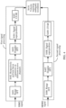
- FIG. 3 is a schematic flowchart of a signal processing method according to an embodiment of this application. Assuming that a radar sends M1 signals in a SIMO mode, then Nr1 receive channels obtain Nr1 ⁇ M1 signals in total. The radar transmits M2 signals through each transmit channel in a MIMO mode, then Nr2 receive channels obtain Nt ⁇ Nr2 ⁇ M2 signals in total.
- S301 to S305 are used for describing a process of performing first signal processing on signals obtained in the SIMO mode
- S306 to S309 are used for describing a process of performing second signal processing on signals obtained in the MIMO mode.
- S310 is used for describing a velocity matching ambiguity resolution process.
- the signals obtained in the SIMO mode may be referred to as SIMO signals.
- the signals obtained in the MIMO mode may be referred to as MIMO signals.
- the method in FIG. 3 includes the following steps.
- the 1-dimension FFT data is data obtained after only 1-dimension FFT transform is performed on an obtained time domain signal.
- Each piece of 1-dimension FFT data may include L pieces of FFT data.
- Y pieces of 1-dimension FFT data obtained by performing the linear prediction may be forward prediction expansion performed on the M1 pieces of 1-dimension FFT data, or may be backward prediction expansion, or may be forward prediction expansion + backward prediction expansion.
- Y is a positive integer.
- the coherent superposition may not be performed on all the Nr1 ⁇ M1 pieces of 1-dimension FFT data obtained by the Nr1 receive channels, but M1 pieces of 1-dimension FFT data corresponding to a receive channel are randomly selected to perform the linear prediction.
- the CFAR may also be replaced by constant missed alarm rate detection, maximum value detection, and eigenvalue detection.
- the performing signal superposition on the Nt ⁇ Nr2third range-Doppler spectrum graphs may include all spectrum graphs in the Nt ⁇ Nr2 third range-Doppler spectrum graphs, or may include partial spectrum graphs.
- the coherent superposition is first performed on FFT data corresponding to a plurality of receive channels, the linear prediction is performed on superposed FFT data, and the first processing data is obtained by performing subsequent data processing. Because the linear prediction is performed, a velocity resolution ⁇ v and a velocity measurement precision ⁇ v of a target obtained in the SIMO mode may be improved. In this way, ranges of the velocity resolution ⁇ v and the velocity measurement precision ⁇ v of the target that are respectively obtained in the SIMO mode and the MIMO mode are closer to each other, thereby helping to improve precision of velocity ambiguity resolution processing performed based on signals obtained in the SIMO mode and the MIMO mode.
- FIG. 4 is a schematic flowchart of a signal processing method according to still another embodiment of this application. Assuming that a radar transmits M1 signals in a SIMO mode, then Nr1 receive channels obtain Nr1 ⁇ M1 signals in total. In a MIMO mode, the radar transmits M2 signals through each transmit channel. Therefore, Nr receive channels obtain Nt ⁇ Nr2 ⁇ M2 pieces of echo data.
- S401 to S405 are used for describing a process of performing first signal processing on signals obtained in the SIMO mode
- S406 to S409 are used for describing a process of performing second signal processing on signals obtained in the MIMO mode.
- S410 is used for describing a velocity matching ambiguity resolution process.
- the signals obtained in the SIMO mode may be referred to as SIMO signals.
- a signal obtained in the MIMO mode may be referred to as a MIMO signal.
- the method in FIG. 4 includes the following steps.
- the 1-dimension FFT data is data obtained after only 1-dimension FFT transform is performed on an obtained time domain signal.
- Each piece of 1-dimension FFT data may include L pieces of FFT data.
- S402. Respectively perform linear prediction on the Nr1 ⁇ M1 pieces of 1-dimension FFT data based on different receive channels to obtain Nr1 ⁇ (M1+Y) pieces of 1-dimension FTT data.
- the Nr1 ⁇ M1 pieces of 1-dimension FFT data may be divided into Nr1 groups of 1-dimension FFT data, and each group of 1-dimension FFT data includes M1 pieces of FFT data.
- the linear prediction may be performed on each group of 1-dimension FFT data to finally obtain the Nr1 ⁇ (M1+Y) pieces of 1-dimension FFT data.
- Y pieces of 1-dimension FFT data obtained by performing the linear prediction may be forward prediction expansion performed on the M1 pieces of 1-dimension FFT data, or may be backward prediction expansion, or may be forward prediction expansion + backward prediction expansion.
- the signal superposition manner may be coherent superposition, or may be incoherent superposition.
- the CFAR may also be replaced by constant missed alarm rate detection, maximum value detection, and eigenvalue detection.
- the linear prediction is first respectively performed on FFT data obtained for different receive channels, then the Doppler FFT analysis and the signal superposition are performed, and the subsequent data processing is performed to obtain the first processing data. Because the linear prediction is performed, a velocity resolution ⁇ v and a velocity measurement precision ⁇ v of a target obtained in the SIMO mode may be improved. In this way, ranges of the velocity resolution ⁇ v and the velocity measurement precision ⁇ v of the target that are respectively obtained in the SIMO mode and the MIMO mode are closer to each other, thereby helping to improve precision of velocity ambiguity resolution processing performed based on signals obtained in the SIMO mode and the MIMO mode.
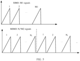
- FIG. 5 is a schematic diagram of signal transmission in a SIMO + MIMO mode according to an embodiment of this application.
- a radar transmits M1 signals in a SIMO mode, and transmits Nt ⁇ M2 signals through Nt transmit antennas in a MIMO mode.
- a maximum unambiguous velocity range v max , velocity resolution ⁇ v, and velocity measurement precision ⁇ v of a target measured in the SIMO mode are respectively represented as Formulas (1) to (3):
- ⁇ represents a transmit signal wavelength
- T c1 represents a PRI of a transmit signal in the SIMO mode
- SNR represents a signal-to-noise ratio of a target in a receive signal.
- ⁇ represents a transmit signal wavelength
- T c2 represents a PRI of a transmit signal in the MIMO mode
- SNR represents a signal-to-noise ratio of a target in a receive signal.
- the SIMO mode is mainly used for performing velocity matching ambiguity resolution processing on signals obtained in the MIMO mode, but is not helpful for CFAR detection and ranging and angle measurement.
- a quantity M1 of signals transmitted by a SIMO radar is far less than a quantity Nt ⁇ M2 of signals transmitted by a MIMO radar.
- v max of a target measured in the SIMO mode is far greater than V max of a target measured in the MIMO mode.
- ⁇ v and ⁇ v measured in the SIMO mode are poorer than those measured in the MIMO mode.
- ranges of ⁇ v and ⁇ v of a target respectively obtained in the SIMO mode and the MIMO mode do not match, which adversely affects precision of velocity matching ambiguity resolution.
- the linear prediction may be performed on signals obtained in the SIMO mode by using a linear prediction (or linear expansion) method, to improve velocity resolution and velocity precision of SIMO, thereby improving the precision of velocity matching ambiguity resolution.
- Nr1 ⁇ M1 pieces of 1-dimension FFT data are obtained.
- the linear prediction is performed based on the Nr1 ⁇ M1 pieces of 1-dimension FFT data, which may include but is not limited to the following several cases.
- Nr1 ⁇ M1 pieces of 1-dimension FFT data are divided into Nr1 groups of 1-dimension FFT data based on different corresponding receive channels.
- Each group of 1-dimension FFT data includes the M1 pieces of 1-dimension FFT data, and the linear prediction is performed on each group of 1-dimension FFT data.
- Nr1 ⁇ M1 pieces of 1-dimension FFT data are divided into the Nr1 groups of 1-dimension FFT data based on different corresponding receive channels.
- Each group of 1-dimension FFT data includes the M1 pieces of 1-dimension FFT data, and one group of 1-dimension FFT data is randomly selected to perform the linear prediction.
- the linear prediction includes forward prediction expansion and backward prediction expansion.
- the forward prediction expansion refers to predicting a future signal by using the existing sampling point information or the signal
- the backward prediction expansion refers to predicting a past signal by using the existing sampling point information or the signal.
- the sample signal may include the 1-dimension FFT data.
- the measurement sample may include all or some of the M1 pieces of 1-dimension FFT data, and the measurement sample may further include FFT data obtained by performing several times of linear prediction before.
- the sample signal may be selected from [X 1 , X 2 , ..., X M1 ].
- the measurement sample may be represented as [X M-p+1 , ..., X M ].
- the measurement sample includes p pieces of 1-dimension FFT data, and p>1.
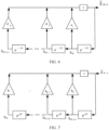
- FIG. 6 is a schematic diagram of a principle of performing forward prediction expansion on data according to an embodiment of this application.
- the forward prediction expansion may further be referred to as forward estimation or forward expansion.
- the forward prediction expansion refers to estimating an (M+1) th signal X M +1 based on an existing measurement sample [X M-p+1 , ..., X M ].
- a forward estimation signal may be represented as X M +1 .
- X M +1 may be represented as Formula (7).
- Formula (8) shows a derivation formula for estimating A f .
- X f [X M-p , ..., X M-1 ]. It should be noted that X M-p also belongs to a known sample signal.
- a f may be solved by using a least square method. Specifically, as shown in Formula (9), a solution that minimizes a norm in Formula (9) is a solution of A f .
- a ⁇ X ⁇ H X ⁇ X ⁇ H ⁇ 1 X M X ⁇ H represents a conjugate transpose matrix of X f .
- FIG. 7 is a schematic diagram of a principle of performing backward expansion on data according to an embodiment of this application.
- the backward prediction expansion may further be referred to as backward estimation or backward expansion.
- the backward prediction expansion refers to estimating an (M-p) th signal X M - p based on a measurement sample [X M-p+1 , ..., X M ].
- a backward estimation signal X M - p may be represented by Formula (11).
- X b X M ⁇ p + 1 , ... , X M .
- backward prediction estimation of a signal may be performed.
- a b may be represented by Formula (12).
- a b X b H X b X b H ⁇ 1 X M ⁇ p X b H represents a conjugate transpose matrix of X b .
- a complex difference (or a phase difference) between samples is e - j ⁇ .
- a complex difference between X M-1 and X M is e - j ⁇ .
- a backward estimation signal of SIMO overlaps a measurement parameter of MIMO.
- an estimated value of SIMO may be corrected by using a measurement result of MIMO.
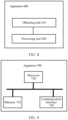
- FIG. 8 is a schematic block diagram of a signal processing apparatus 600 according to an embodiment of this application.
- the apparatus 600 may perform the method in FIG. 2 to FIG. 4 of this application.
- the apparatus 600 includes an obtaining unit 610 and a processing unit 620.
- the obtaining unit 610 is configured to obtain Nr1 ⁇ M1 signals, where the Nr1 ⁇ M1 signals are echo signals of M1 signals that are sent by a radar to a target in a SIMO mode, the SIMO mode corresponds to one transmit channel and Nr1 receive channels, and Nr1 and M1 are integers greater than 0.
- the obtaining unit 610 is further configured to obtain Nt ⁇ Nr2 ⁇ M2 signals.
- the Nt ⁇ Nr2 ⁇ M2 signals are echo signals of M2 signals that are sent by the radar to the target in a MIMO mode, the MIMO mode corresponds to Nt transmit channels and Nr2 receive channels, and Nt, Nr2, and M2 are integers greater than 0.
- the processing unit 620 is configured to perform first signal processing on the Nr1 ⁇ M1 signals to obtain first processing data.
- the first signal processing includes sequentially performing the following processing: range FFT analysis, linear prediction, and Doppler FFT analysis.
- the linear prediction is used to predict FFT data before or after a time domain of FFT data obtained by performing the range FFT analysis.
- the processing unit 620 is further configured to perform second signal processing on the Nt ⁇ Nr2 ⁇ M2 signals to obtain second processing data.
- the second signal processing includes range FFT analysis and Doppler FFT analysis.
- the processing unit 620 is further configured to perform velocity matching ambiguity resolution processing based on the first processing data and the second processing data.
- the apparatus 600 may include the radar 100 in FIG. 1 .
- the obtaining unit 610 and the processing unit 620 may be the processing unit 130 in FIG. 1 .
- a signal obtained by the obtaining unit 610 may be a signal received through the receiver 120 in FIG. 1 .
- FIG. 9 is a schematic block diagram of a signal processing apparatus 700 according to an embodiment of this application.
- the apparatus 700 may perform the method in FIG. 2 to FIG. 4 of this application.
- the apparatus 700 includes one or more memories 710, one or more communication interfaces 720, and one or more processors 730.
- the processor 730 is configured to control the communication interface 720 to receive and send a signal.
- the memory 710 is configured to store a computer program.
- the processor 730 is configured to call the computer program from a memory 2010 and run the computer program, so that the apparatus 700 performs a corresponding procedure and/or operation in the method embodiments of this application.
- the apparatus 700 may perform the steps performed in FIG. 2 to FIG. 4 .
- details are not described herein again.
- the apparatus 700 may include the radar 100 in FIG. 1 .
- the processor 730 may include the processing unit 130 in FIG. 1 .
- the communication interface 720 may include the receiver 120 in FIG. 1 .
- the units described as separate parts may or may not be physically separate, and parts displayed as units may or may not be physical units, may be located in one position, or may be distributed on a plurality of network units. Some or all of the units may be selected based on actual requirements to achieve the objectives of the solutions of embodiments.
- the foregoing storage medium includes any medium that can store program code, such as a USB flash drive, a removable hard disk, a read-only memory (read-only memory, ROM), a random access memory (random access memory, RAM), a magnetic disk, or an optical disc.
- program code such as a USB flash drive, a removable hard disk, a read-only memory (read-only memory, ROM), a random access memory (random access memory, RAM), a magnetic disk, or an optical disc.
Landscapes
- Engineering & Computer Science (AREA)
- Radar, Positioning & Navigation (AREA)
- Remote Sensing (AREA)
- Computer Networks & Wireless Communication (AREA)
- Physics & Mathematics (AREA)
- General Physics & Mathematics (AREA)
- Radar Systems Or Details Thereof (AREA)
Claims (15)
- Signalverarbeitungsverfahren, umfassend:Erlangen (S201) von Nr1×M1 Signalen, wobei die Nr1×M1 Signale Echosignale von M1 Signalen sind, die von einem Radar in einem Modus mit einer einzigen Eingabe und mehreren Ausgaben (SIMO-Modus) an ein Ziel gesendet werden, wobei der SIMO-Modus einem Sendekanal und Nr1 Empfangskanälen entspricht und Nr1 und M1 ganze Zahlen größer als 1 sind;Erlangen (S202) von Nt×Nr2×M2 Signalen, wobei die Nt×Nr2×M2 Signale Echosignale von M2 Signalen sind, die von dem Radar in einem Modus mit mehreren Eingaben und mehreren Ausgaben (MIMO-Modus) an das Ziel gesendet werden, wobei der MIMO-Modus Nt Sendekanälen und Nr2 Empfangskanälen entspricht und Nt, Nr2 und M2 ganze Zahlen größer als 1 sind; gekennzeichnet durchein Zeitintervall zwischen einem Startzeitpunkt zum Senden der M1 Signale im SIMO-Modus und einem Startzeitpunkt zum Senden der M2 Signale im MIMO-Modus, das kleiner als ein voreingestellter Wert ist;Durchführen (S203) einer ersten Signalverarbeitung an den Nr1×M1 Signalen, um erste Verarbeitungsdaten zu erlangen, wobei die erste Signalverarbeitung sequenzielles Durchführen der folgenden Verarbeitung umfasst: Range-Analyse mit schneller Fourier-Transformation (Range-FFT-Analyse), lineare Vorhersage und Doppler-FFT-Analyse und wobei die lineare Vorhersage verwendet wird, um FFT-Daten vor oder nach einer Zeitdomäne von FFT-Daten, die durch Durchführen der Range-FFT-Analyse erlangt wurden, vorherzusagen; wobei die lineare Vorhersage mindestens eines der Folgenden umfasst: Vorwärtsvorhersageerweiterung und Rückwärtsvorhersageerweiterung; wobei sich die Vorwärtsvorhersageerweiterung auf Vorhersagen eines zukünftigen Signals unter Verwendung vorhandener Abtastpunktinformationen oder des Signals bezieht und sich die Rückwärtsvorhersageerweiterung auf Vorhersagen eines vergangenen Signals unter Verwendung vorhandener Abtastpunktinformationen oder des Signals bezieht;Durchführen (S205) einer zweiten Signalverarbeitung an den Nt×Nr2×M2 Signalen, um zweite Verarbeitungsdaten zu erlangen, wobei die zweite Signalverarbeitung eine Range-FFT-Analyse und eine Doppler-FFT-Analyse umfasst; undDurchführen (S205) einer Geschwindigkeitsanpassungs-Mehrdeutigkeitsauflösungsverarbeitung basierend auf den ersten Verarbeitungsdaten und den zweiten Verarbeitungsdaten.
- Verfahren nach Anspruch 1, wobei die erste Signalverarbeitung sequentielles Durchführen der folgenden Verarbeitung umfasst:
die Range-FFT-Analyse, kohärente Überlagerung von Empfangskanälen, die lineare Vorhersage, die Doppler-FFT-Analyse und die konstante Falschalarmratenerkennung (CFAR-Erkennung). - Verfahren nach Anspruch 1, wobei die erste Signalverarbeitung sequentielles Durchführen der folgenden Verarbeitung umfasst:
die Range-FFT-Analyse, die lineare Vorhersage, die Doppler-FFT-Analyse, Signalüberlagerung und CFAR. - Verfahren nach einem der Ansprüche 1 bis 3, wobei die zweite Signalverarbeitung ferner sequentielles Durchführen der folgenden Verarbeitung umfasst: die Range-FFT-Analyse, die Doppler-FFT-Analyse, Signalüberlagerung und CFAR.
- Verfahren nach Anspruch 2, wobei das Durchführen einer ersten Signalverarbeitung an den Nr1×M1 Signalen zum Erlangen erster Verarbeitungsdaten Folgendes umfasst:Durchführen der Range-FFT-Analyse an den Nr1×M1 Signalen, um Nr1×M1 Teile eindimensionaler FFT-Daten zu erlangen;Durchführen der kohärenten Überlagerung von Empfangskanälen an den Nr1×M1 Teilen eindimensionaler FFT-Daten, um M1 Teile eindimensionaler FFT-Daten zu erlangen;Durchführen der linearen Vorhersage an den M1 Teilen eindimensionaler FFT-Daten, um M1+Y Teile eindimensionaler FFT-Daten zu erlangen, wobei Y eine positive ganze Zahl ist;Durchführen der Doppler-FFT-Analyse an den M1+Y Teilen der eindimensionalen FFT-Daten, um ein Range-Doppler-Spektrumdiagramm zu erhalten; undDurchführen der CFAR-Erkennung an dem Range-Doppler-Spektrumdiagramm, um die ersten Verarbeitungsdaten zu erlangen.
- Verfahren nach Anspruch 3, wobei das Durchführen einer ersten Signalverarbeitung an den Nr1×M1 Signalen zum Erlangen erster Verarbeitungsdaten Folgendes umfasst:Durchführen der Range-FFT-Analyse an den Nr1×M1 Signalen, um Nr1×M1 Teile eindimensionaler FFT-Daten zu erlangen;jeweils Durchführen der linearen Vorhersage an den Nr1×M1 Teilen eindimensionaler FFT-Daten basierend auf verschiedenen Empfangskanälen, um Nr1×(M1+Y) Teile eindimensionaler FFT-Daten zu erlangen, wobei Y eine positive ganze Zahl ist;jeweils Durchführen der Doppler-FFT-Analyse an den Nr1×(M1+Y) Teilen eindimensionaler FFT-Daten basierend auf verschiedenen Empfangskanälen, um Nr1 erste Range-Doppler-Spektrumdiagramme zu erlangen;Durchführen der Signalüberlagerung an den Nr1 ersten Range-Doppler-Spektrumdiagrammen, um ein zweites Range-Doppler-Spektrumdiagramm zu erlangen; undDurchführen der CFAR-Erkennung an dem zweiten Range - Doppler-Spektrumdiagramm, um die ersten Verarbeitungsdaten zu erlangen.
- Verfahren nach Anspruch 4, wobei das Durchführen einer zweiten Signalverarbeitung an den Nt×Nr2×M2 Signalen zum Erlangen zweiter Verarbeitungsdaten Folgendes umfasst:Durchführen der Range-FFT-Analyse an den Nt×Nr2×M2 Signalen, um Nt×Nr2×M2 Teile eindimensionaler FFT-Daten zu erlangen;jeweils Durchführen der Doppler-FFT-Analyse an den Nt×Nr2×M2 Teilen eindimensionaler FFT-Daten, um Nt×Nr2dritte Range-Doppler-Spektrumdiagramme zu erlangen;Durchführen der Signalüberlagerung an den Nt×Nr2dritten Range-Doppler-Spektrumdiagrammen, um ein viertes Range-Doppler-Spektrumdiagramm zu erlangen; undDurchführen der CFAR-Erkennung an dem vierten Range - Doppler-Spektrumdiagramm, um die zweiten Verarbeitungsdaten zu erlangen.
- Signalverarbeitungsvorrichtung, umfassend:eine Erlangungseinheit (610), die dazu konfiguriert ist, Nr1×M1 Signale zu erlangen, wobei die Nr1×M1 Signale Echosignale von M1 Signalen sind, die von einem Radar in einem Modus mit einer einzigen Eingabe und mehreren Ausgaben (SIMO-Modus) an ein Ziel gesendet werden, wobei der SIMO-Modus einem Sendekanal und Nr1 Empfangskanälen entspricht und Nr1 und M1 ganze Zahlen größer als 1 sind;die Erlangungseinheit ferner dazu konfiguriert ist, Nt×Nr2×M2 Signale zu erlangen, wobei die Nt×Nr2×M2 Signale Echosignale von M2 Signalen sind, die von dem Radar in einem Modus mit mehreren Eingaben und mehreren Ausgaben (MIMO-Modus) an das Ziel gesendet werden, wobei der MIMO-Modus Nt Sendekanälen und Nr2 Empfangskanälen entspricht und Nt, Nr2 und M2 ganze Zahlen größer als 1 sind;gekennzeichnet durchein Zeitintervall zwischen einem Startzeitpunkt zum Senden der M1 Signale im SIMO-Modus und einem Startzeitpunkt zum Senden der M2 Signale im MIMO-Modus, das kleiner als ein voreingestellter Wert ist;
undeine Verarbeitungseinheit (620), die dazu konfiguriert ist, eine erste Signalverarbeitung an den Nr1×M1 Signalen durchzuführen, um erste Verarbeitungsdaten zu erlangen, wobei die erste Signalverarbeitung sequenzielles Durchführen der folgenden Verarbeitung umfasst: Range-Analyse mit schneller Fourier-Transformation (Range-FFT-Analyse), lineare Vorhersage und Doppler-FFT-Analyse und wobei die lineare Vorhersage verwendet wird, um FFT-Daten vor oder nach einer Zeitdomäne von FFT-Daten, die durch Durchführen der Range-FFT-Analyse erlangt wurden, vorherzusagen; wobei die lineare Vorhersage mindestens eines der Folgenden umfasst: Vorwärtsvorhersageerweiterung und Rückwärtsvorhersageerweiterung; wobei sich die Vorwärtsvorhersageerweiterung auf Vorhersagen eines zukünftigen Signals unter Verwendung vorhandener Abtastpunktinformationen oder des Signals bezieht und sich die Rückwärtsvorhersageerweiterung auf Vorhersagen eines vergangenen Signals unter Verwendung vorhandener Abtastpunktinformationen oder des Signals bezieht;die Verarbeitungseinheit ferner dazu konfiguriert ist, eine zweite Signalverarbeitung an den Nt×Nr2×M2 Signalen durchzuführen, um zweite Verarbeitungsdaten zu erlangen, wobei die zweite Signalverarbeitung eine Range-FFT-Analyse und eine Doppler-FFT-Analyse umfasst; unddie Verarbeitungseinheit ferner dazu konfiguriert ist, eine Geschwindigkeitsanpassungs-Mehrdeutigkeitsauflösungsverarbeitung basierend auf den ersten Verarbeitungsdaten und den zweiten Verarbeitungsdaten durchzuführen. - Vorrichtung nach Anspruch 8, wobei die erste Signalverarbeitung sequentielles Durchführen der folgenden Verarbeitung umfasst: die Range-FFT-Analyse, kohärente Überlagerung von Empfangskanälen, die lineare Vorhersage, die Doppler-FFT-Analyse und die konstante Falschalarmratenerkennung (CFAR-Erkennung).
- Vorrichtung nach Anspruch 8, wobei die erste Signalverarbeitung sequentielles Durchführen der folgenden Verarbeitung umfasst: die Range-FFT-Analyse, die lineare Vorhersage, die Doppler-FFT-Analyse, Signalüberlagerung und CFAR.
- Vorrichtung nach einem der Ansprüche 8 bis 10, wobei die zweite Signalverarbeitung sequentielles Durchführen der folgenden Verarbeitung umfasst: die Range-FFT-Analyse, die Doppler-FFT-Analyse, Signalüberlagerung und CFAR.
- Vorrichtung nach Anspruch 9, wobei die Verarbeitungseinheit speziell zu Folgendem konfiguriert ist: Durchführen der Range-FFT-Analyse an den Nr1×M1 Signalen, um Nr1×M1 Teile eindimensionaler FFT-Daten zu erhalten; Durchführen der kohärenten Überlagerung von Empfangskanälen an den Nr1×M1 Teilen eindimensionaler FFT-Daten, um M1 Teile eindimensionaler FFT-Daten zu erhalten; Durchführen der linearen Vorhersage an den M1 Teilen eindimensionaler FFT-Daten, um M1+Y Teile eindimensionaler FFT-Daten zu erhalten, wobei Y eine positive ganze Zahl ist; Durchführen der Doppler-FFT-Analyse an den M1+Y Teilen eindimensionaler FFT-Daten, um ein Range-Doppler-Spektrumdiagramm zu erhalten; und Durchführen der CFAR an dem Range - Doppler - Spektrumdiagramm, um die ersten Verarbeitungsdaten zu erhalten.
- Vorrichtung nach Anspruch 10, wobei die Verarbeitungseinheit speziell zu Folgendem konfiguriert ist: Durchführen der Range-FFT-Analyse an den Nr1×M1 Signalen, um Nr1×M1 Teile eindimensionaler FFT-Daten zu erhalten; jeweils Durchführen der linearen Vorhersage an den Nr1×M1 Teilen eindimensionaler FFT-Daten basierend auf verschiedenen Empfangskanälen, um Nr1×(M1+Y) Teile eindimensionaler FFT-Daten zu erlangen; jeweils Durchführen der Doppler-FFT-Analyse an den Nr1×(M1+Y) Teilen eindimensionaler FFT-Daten basierend auf verschiedenen Empfangskanälen, um Nr1 erste Range-Doppler-Spektrumdiagramme zu erlangen, wobei Y eine positive ganze Zahl ist; Durchführen der Signalüberlagerung an den Nr1 ersten Range-Doppler-Spektrumdiagrammen, um ein zweites Range-Doppler-Spektrumdiagramm zu erlangen; und Durchführen der CFAR an dem zweiten Range-Doppler-Spektrumdiagramm, um die ersten Verarbeitungsdaten zu erhalten.
- Vorrichtung nach Anspruch 11, wobei die Verarbeitungseinheit speziell zu Folgendem konfiguriert ist: Durchführen der Range-FFT-Analyse an den Nt×Nr2×M2 Signalen, um Nt×Nr2×M2 Teile eindimensionaler FFT-Daten zu erlangen; jeweils Durchführen der Doppler-FFT-Analyse an den Nt×Nr2×M2 Teilen eindimensionaler FFT-Daten, um Nt×Nr2dritte Range-Doppler-Spektrumdiagramme zu erlangen; Durchführen der Signalüberlagerung an den Nt×Nr2 dritten Range-Doppler-Spektrumdiagrammen, um ein viertes Range-Doppler-Spektrumdiagramm zu erlangen; und Durchführen der CFAR an dem vierten Range - Doppler - Spektrumdiagramm, um die zweiten Verarbeitungsdaten zu erlangen.
- Lesbares Speichermedium, umfassend ein Programm oder Anweisungen, wobei, wenn das Programm oder die Anweisungen auf einem Computer ausgeführt werden, das Verfahren nach einem der Ansprüche 1 bis 7 durchgeführt wird.
Applications Claiming Priority (1)
| Application Number | Priority Date | Filing Date | Title |
|---|---|---|---|
| PCT/CN2020/106864 WO2022027241A1 (zh) | 2020-08-04 | 2020-08-04 | 信号处理方法和装置 |
Publications (3)
| Publication Number | Publication Date |
|---|---|
| EP4184797A1 EP4184797A1 (de) | 2023-05-24 |
| EP4184797A4 EP4184797A4 (de) | 2023-07-26 |
| EP4184797B1 true EP4184797B1 (de) | 2024-10-09 |
Family
ID=75609560
Family Applications (1)
| Application Number | Title | Priority Date | Filing Date |
|---|---|---|---|
| EP20948325.4A Active EP4184797B1 (de) | 2020-08-04 | 2020-08-04 | Signalverarbeitungsverfahren und -vorrichtung |
Country Status (4)
| Country | Link |
|---|---|
| US (1) | US12313768B2 (de) |
| EP (1) | EP4184797B1 (de) |
| CN (1) | CN112740069B (de) |
| WO (1) | WO2022027241A1 (de) |
Families Citing this family (3)
| Publication number | Priority date | Publication date | Assignee | Title |
|---|---|---|---|---|
| CN122449516A (zh) * | 2021-12-28 | 2026-07-24 | 加特兰微电子科技(上海)股份有限公司 | 目标检测的方法、装置及相关设备 |
| CN114325632B (zh) * | 2022-03-14 | 2022-06-17 | 广东大湾区空天信息研究院 | Mimo体制下的毫米波雷达速度解模糊方法及处理设备 |
| CN117388814A (zh) * | 2022-07-11 | 2024-01-12 | 加特兰微电子科技(上海)有限公司 | 信号处理方法、装置、雷达、介质、程序产品及终端 |
Family Cites Families (11)
| Publication number | Priority date | Publication date | Assignee | Title |
|---|---|---|---|---|
| JP4079084B2 (ja) | 2003-12-16 | 2008-04-23 | 富士通株式会社 | レーダ目標識別装置 |
| WO2007108080A1 (ja) * | 2006-03-20 | 2007-09-27 | Fujitsu Limited | 基地局およびそのmimo-ofdm通信方法 |
| JP5432882B2 (ja) * | 2010-11-25 | 2014-03-05 | 株式会社日立製作所 | 分散アンテナシステム、分散アンテナ切替方法、基地局装置及びアンテナスイッチ装置 |
| JP6479602B2 (ja) * | 2015-08-06 | 2019-03-06 | 株式会社東芝 | レーダ装置及びそのレーダ信号処理方法 |
| US10261179B2 (en) * | 2016-04-07 | 2019-04-16 | Uhnder, Inc. | Software defined automotive radar |
| US10627483B2 (en) * | 2016-07-09 | 2020-04-21 | Texas Instruments Incorporated | Methods and apparatus for velocity detection in MIMO radar including velocity ambiguity resolution |
| US10670712B2 (en) * | 2018-01-04 | 2020-06-02 | Analog Devices, Inc. | Methods and apparatus for a MIMO radar |
| CN108594233B (zh) * | 2018-04-24 | 2020-07-14 | 森思泰克河北科技有限公司 | 一种基于mimo汽车雷达的速度解模糊方法 |
| CN110412558B (zh) * | 2019-07-03 | 2022-05-17 | 南京理工大学 | 基于tdm mimo的解车载fmcw雷达速度模糊方法 |
| CN111239721B (zh) * | 2020-02-13 | 2022-05-03 | 南京航空航天大学 | 车载mimo雷达求熵解速度模糊的方法 |
| CN111308437B (zh) * | 2020-02-27 | 2022-03-22 | 南京慧尔视智能科技有限公司 | 一种毫米波mimo交通雷达求熵解速度模糊的方法 |
-
2020
- 2020-08-04 EP EP20948325.4A patent/EP4184797B1/de active Active
- 2020-08-04 CN CN202080005160.9A patent/CN112740069B/zh active Active
- 2020-08-04 WO PCT/CN2020/106864 patent/WO2022027241A1/zh not_active Ceased
-
2023
- 2023-02-03 US US18/164,398 patent/US12313768B2/en active Active
Also Published As
| Publication number | Publication date |
|---|---|
| WO2022027241A1 (zh) | 2022-02-10 |
| EP4184797A1 (de) | 2023-05-24 |
| CN112740069A (zh) | 2021-04-30 |
| EP4184797A4 (de) | 2023-07-26 |
| US20230184886A1 (en) | 2023-06-15 |
| CN112740069B (zh) | 2022-03-08 |
| US12313768B2 (en) | 2025-05-27 |
Similar Documents
| Publication | Publication Date | Title |
|---|---|---|
| CN111308437B (zh) | 一种毫米波mimo交通雷达求熵解速度模糊的方法 | |
| EP3953729B1 (de) | Radardetektion eines sich bewegenden objekts mit wellenformtrennungsresten | |
| CN110431437B (zh) | 用于求取雷达目标的横向相对速度分量的方法和设备 | |
| US12313768B2 (en) | Signal processing method and apparatus | |
| CN111373282B (zh) | 用于fmcw雷达系统的雷达处理链 | |
| US11131749B2 (en) | MIMO radar sensor for motor vehicles | |
| EP4471458A1 (de) | Verfahren und vorrichtung zur auflösung der mehrdeutigkeit einer bewegten zielgeschwindigkeit sowie elektronische vorrichtung und speichermedium | |
| EP3060940B1 (de) | Winkelauflösung in einem radar | |
| US12222441B2 (en) | TDM FMCW radar apparatus and signal processing method of apparatus | |
| US11047974B1 (en) | Systems and methods for virtual doppler and/or aperture enhancement | |
| US12411207B2 (en) | Method and apparatus with radar signal processing | |
| CN101349752A (zh) | 用于估计到达信号数的设备和方法 | |
| CN111239721B (zh) | 车载mimo雷达求熵解速度模糊的方法 | |
| US12487322B2 (en) | Device and method with radar signal processing | |
| JP2009025159A (ja) | レーダ装置 | |
| EP4471457A1 (de) | Verfahren und vorrichtung zur auflösung von geschwindigkeitsmehrdeutigkeit für sich bewegendes ziel, elektronische vorrichtung und speichermedium | |
| EP4191279A1 (de) | Tdm-fmcw-radarvorrichtung und signalverarbeitungsverfahren der vorrichtung | |
| CN114814817B (zh) | 运动目标速度解模糊方法、装置、电子设备及存储介质 | |
| EP4343363A1 (de) | Auflösung von doppler-mehrdeutigkeiten in tdm-mimo-radaren auf der basis der räumlichen phasenänderungsgeschwindigkeit | |
| KR20250155555A (ko) | 레이더 각도 추정을 위한 방법 | |
| CN116256716B (zh) | 基于加权线性拟合的毫米波雷达超分辨方法和系统 | |
| US11150338B2 (en) | Azimuth calculation device and azimuth calculation method | |
| CN117092634A (zh) | 雷达测速解模糊方法、装置及存储介质 | |
| US11269052B2 (en) | Signal processing method | |
| EP4369025B1 (de) | Mimo-radarsignalverarbeitungsvorrichtung, empfangssignalverarbeitungsvorrichtung dafür und verfahren zur unterscheidung des ausbreitungsmodus eines interessierenden empfangssignalvektors |
Legal Events
| Date | Code | Title | Description |
|---|---|---|---|
| STAA | Information on the status of an ep patent application or granted ep patent |
Free format text: STATUS: THE INTERNATIONAL PUBLICATION HAS BEEN MADE |
|
| PUAI | Public reference made under article 153(3) epc to a published international application that has entered the european phase |
Free format text: ORIGINAL CODE: 0009012 |
|
| STAA | Information on the status of an ep patent application or granted ep patent |
Free format text: STATUS: REQUEST FOR EXAMINATION WAS MADE |
|
| 17P | Request for examination filed |
Effective date: 20230217 |
|
| AK | Designated contracting states |
Kind code of ref document: A1 Designated state(s): AL AT BE BG CH CY CZ DE DK EE ES FI FR GB GR HR HU IE IS IT LI LT LU LV MC MK MT NL NO PL PT RO RS SE SI SK SM TR |
|
| A4 | Supplementary search report drawn up and despatched |
Effective date: 20230627 |
|
| RIC1 | Information provided on ipc code assigned before grant |
Ipc: G01S 13/58 20060101ALI20230621BHEP Ipc: G01S 13/42 20060101ALI20230621BHEP Ipc: G01S 13/34 20060101ALI20230621BHEP Ipc: G01S 13/26 20060101ALI20230621BHEP Ipc: G01S 7/35 20060101ALI20230621BHEP Ipc: G01S 7/288 20060101ALI20230621BHEP Ipc: H04B 7/02 20180101ALI20230621BHEP Ipc: H04B 7/04 20170101AFI20230621BHEP |
|
| DAV | Request for validation of the european patent (deleted) | ||
| DAX | Request for extension of the european patent (deleted) | ||
| GRAP | Despatch of communication of intention to grant a patent |
Free format text: ORIGINAL CODE: EPIDOSNIGR1 |
|
| STAA | Information on the status of an ep patent application or granted ep patent |
Free format text: STATUS: GRANT OF PATENT IS INTENDED |
|
| RIC1 | Information provided on ipc code assigned before grant |
Ipc: G01S 13/58 20060101ALI20240315BHEP Ipc: G01S 13/42 20060101ALI20240315BHEP Ipc: G01S 13/34 20060101ALI20240315BHEP Ipc: G01S 13/26 20060101ALI20240315BHEP Ipc: G01S 7/35 20060101ALI20240315BHEP Ipc: G01S 7/288 20060101ALI20240315BHEP Ipc: H04B 7/02 20180101ALI20240315BHEP Ipc: H04B 7/04 20170101AFI20240315BHEP |
|
| INTG | Intention to grant announced |
Effective date: 20240411 |
|
| GRAS | Grant fee paid |
Free format text: ORIGINAL CODE: EPIDOSNIGR3 |
|
| GRAA | (expected) grant |
Free format text: ORIGINAL CODE: 0009210 |
|
| STAA | Information on the status of an ep patent application or granted ep patent |
Free format text: STATUS: THE PATENT HAS BEEN GRANTED |
|
| P01 | Opt-out of the competence of the unified patent court (upc) registered |
Free format text: CASE NUMBER: APP_48761/2024 Effective date: 20240827 |
|
| AK | Designated contracting states |
Kind code of ref document: B1 Designated state(s): AL AT BE BG CH CY CZ DE DK EE ES FI FR GB GR HR HU IE IS IT LI LT LU LV MC MK MT NL NO PL PT RO RS SE SI SK SM TR |
|
| REG | Reference to a national code |
Ref country code: CH Ref legal event code: EP |
|
| REG | Reference to a national code |
Ref country code: DE Ref legal event code: R096 Ref document number: 602020039383 Country of ref document: DE |
|
| REG | Reference to a national code |
Ref country code: IE Ref legal event code: FG4D |
|
| REG | Reference to a national code |
Ref country code: DE Ref legal event code: R081 Ref document number: 602020039383 Country of ref document: DE Owner name: SHENZHEN YINWANG INTELLIGENT TECHNOLOGIES CO.,, CN Free format text: FORMER OWNER: HUAWEI TECHNOLOGIES CO., LTD., SHENZHEN, GUANGDONG, CN |
|
| RAP2 | Party data changed (patent owner data changed or rights of a patent transferred) |
Owner name: SHENZHEN YINWANG INTELLIGENTTECHNOLOGIES CO., LTD. |
|
| REG | Reference to a national code |
Ref country code: LT Ref legal event code: MG9D |
|
| REG | Reference to a national code |
Ref country code: NL Ref legal event code: MP Effective date: 20241009 |
|
| REG | Reference to a national code |
Ref country code: AT Ref legal event code: MK05 Ref document number: 1731708 Country of ref document: AT Kind code of ref document: T Effective date: 20241009 |
|
| PG25 | Lapsed in a contracting state [announced via postgrant information from national office to epo] |
Ref country code: NL Free format text: LAPSE BECAUSE OF FAILURE TO SUBMIT A TRANSLATION OF THE DESCRIPTION OR TO PAY THE FEE WITHIN THE PRESCRIBED TIME-LIMIT Effective date: 20241009 |
|
| PG25 | Lapsed in a contracting state [announced via postgrant information from national office to epo] |
Ref country code: NL Free format text: LAPSE BECAUSE OF FAILURE TO SUBMIT A TRANSLATION OF THE DESCRIPTION OR TO PAY THE FEE WITHIN THE PRESCRIBED TIME-LIMIT Effective date: 20241009 |
|
| PG25 | Lapsed in a contracting state [announced via postgrant information from national office to epo] |
Ref country code: HR Free format text: LAPSE BECAUSE OF FAILURE TO SUBMIT A TRANSLATION OF THE DESCRIPTION OR TO PAY THE FEE WITHIN THE PRESCRIBED TIME-LIMIT Effective date: 20241009 Ref country code: IS Free format text: LAPSE BECAUSE OF FAILURE TO SUBMIT A TRANSLATION OF THE DESCRIPTION OR TO PAY THE FEE WITHIN THE PRESCRIBED TIME-LIMIT Effective date: 20250209 Ref country code: PT Free format text: LAPSE BECAUSE OF FAILURE TO SUBMIT A TRANSLATION OF THE DESCRIPTION OR TO PAY THE FEE WITHIN THE PRESCRIBED TIME-LIMIT Effective date: 20250210 |
|
| PG25 | Lapsed in a contracting state [announced via postgrant information from national office to epo] |
Ref country code: FI Free format text: LAPSE BECAUSE OF FAILURE TO SUBMIT A TRANSLATION OF THE DESCRIPTION OR TO PAY THE FEE WITHIN THE PRESCRIBED TIME-LIMIT Effective date: 20241009 |
|
| PG25 | Lapsed in a contracting state [announced via postgrant information from national office to epo] |
Ref country code: BG Free format text: LAPSE BECAUSE OF FAILURE TO SUBMIT A TRANSLATION OF THE DESCRIPTION OR TO PAY THE FEE WITHIN THE PRESCRIBED TIME-LIMIT Effective date: 20241009 |
|
| PG25 | Lapsed in a contracting state [announced via postgrant information from national office to epo] |
Ref country code: ES Free format text: LAPSE BECAUSE OF FAILURE TO SUBMIT A TRANSLATION OF THE DESCRIPTION OR TO PAY THE FEE WITHIN THE PRESCRIBED TIME-LIMIT Effective date: 20241009 |
|
| PG25 | Lapsed in a contracting state [announced via postgrant information from national office to epo] |
Ref country code: NO Free format text: LAPSE BECAUSE OF FAILURE TO SUBMIT A TRANSLATION OF THE DESCRIPTION OR TO PAY THE FEE WITHIN THE PRESCRIBED TIME-LIMIT Effective date: 20250109 |
|
| PG25 | Lapsed in a contracting state [announced via postgrant information from national office to epo] |
Ref country code: GR Free format text: LAPSE BECAUSE OF FAILURE TO SUBMIT A TRANSLATION OF THE DESCRIPTION OR TO PAY THE FEE WITHIN THE PRESCRIBED TIME-LIMIT Effective date: 20250110 Ref country code: LV Free format text: LAPSE BECAUSE OF FAILURE TO SUBMIT A TRANSLATION OF THE DESCRIPTION OR TO PAY THE FEE WITHIN THE PRESCRIBED TIME-LIMIT Effective date: 20241009 Ref country code: AT Free format text: LAPSE BECAUSE OF FAILURE TO SUBMIT A TRANSLATION OF THE DESCRIPTION OR TO PAY THE FEE WITHIN THE PRESCRIBED TIME-LIMIT Effective date: 20241009 |
|
| PG25 | Lapsed in a contracting state [announced via postgrant information from national office to epo] |
Ref country code: PL Free format text: LAPSE BECAUSE OF FAILURE TO SUBMIT A TRANSLATION OF THE DESCRIPTION OR TO PAY THE FEE WITHIN THE PRESCRIBED TIME-LIMIT Effective date: 20241009 |
|
| PG25 | Lapsed in a contracting state [announced via postgrant information from national office to epo] |
Ref country code: RS Free format text: LAPSE BECAUSE OF FAILURE TO SUBMIT A TRANSLATION OF THE DESCRIPTION OR TO PAY THE FEE WITHIN THE PRESCRIBED TIME-LIMIT Effective date: 20250109 |
|
| PG25 | Lapsed in a contracting state [announced via postgrant information from national office to epo] |
Ref country code: SM Free format text: LAPSE BECAUSE OF FAILURE TO SUBMIT A TRANSLATION OF THE DESCRIPTION OR TO PAY THE FEE WITHIN THE PRESCRIBED TIME-LIMIT Effective date: 20241009 |
|
| PG25 | Lapsed in a contracting state [announced via postgrant information from national office to epo] |
Ref country code: DK Free format text: LAPSE BECAUSE OF FAILURE TO SUBMIT A TRANSLATION OF THE DESCRIPTION OR TO PAY THE FEE WITHIN THE PRESCRIBED TIME-LIMIT Effective date: 20241009 |
|
| REG | Reference to a national code |
Ref country code: DE Ref legal event code: R097 Ref document number: 602020039383 Country of ref document: DE |
|
| PG25 | Lapsed in a contracting state [announced via postgrant information from national office to epo] |
Ref country code: EE Free format text: LAPSE BECAUSE OF FAILURE TO SUBMIT A TRANSLATION OF THE DESCRIPTION OR TO PAY THE FEE WITHIN THE PRESCRIBED TIME-LIMIT Effective date: 20241009 |
|
| PGFP | Annual fee paid to national office [announced via postgrant information from national office to epo] |
Ref country code: FR Payment date: 20250623 Year of fee payment: 6 |
|
| PG25 | Lapsed in a contracting state [announced via postgrant information from national office to epo] |
Ref country code: RO Free format text: LAPSE BECAUSE OF FAILURE TO SUBMIT A TRANSLATION OF THE DESCRIPTION OR TO PAY THE FEE WITHIN THE PRESCRIBED TIME-LIMIT Effective date: 20241009 |
|
| PG25 | Lapsed in a contracting state [announced via postgrant information from national office to epo] |
Ref country code: SK Free format text: LAPSE BECAUSE OF FAILURE TO SUBMIT A TRANSLATION OF THE DESCRIPTION OR TO PAY THE FEE WITHIN THE PRESCRIBED TIME-LIMIT Effective date: 20241009 |
|
| PG25 | Lapsed in a contracting state [announced via postgrant information from national office to epo] |
Ref country code: CZ Free format text: LAPSE BECAUSE OF FAILURE TO SUBMIT A TRANSLATION OF THE DESCRIPTION OR TO PAY THE FEE WITHIN THE PRESCRIBED TIME-LIMIT Effective date: 20241009 |
|
| PG25 | Lapsed in a contracting state [announced via postgrant information from national office to epo] |
Ref country code: IT Free format text: LAPSE BECAUSE OF FAILURE TO SUBMIT A TRANSLATION OF THE DESCRIPTION OR TO PAY THE FEE WITHIN THE PRESCRIBED TIME-LIMIT Effective date: 20241009 |
|
| PLBE | No opposition filed within time limit |
Free format text: ORIGINAL CODE: 0009261 |
|
| STAA | Information on the status of an ep patent application or granted ep patent |
Free format text: STATUS: NO OPPOSITION FILED WITHIN TIME LIMIT |
|
| PG25 | Lapsed in a contracting state [announced via postgrant information from national office to epo] |
Ref country code: SE Free format text: LAPSE BECAUSE OF FAILURE TO SUBMIT A TRANSLATION OF THE DESCRIPTION OR TO PAY THE FEE WITHIN THE PRESCRIBED TIME-LIMIT Effective date: 20241009 |
|
| 26N | No opposition filed |
Effective date: 20250710 |
|
| PGFP | Annual fee paid to national office [announced via postgrant information from national office to epo] |
Ref country code: DE Payment date: 20250618 Year of fee payment: 6 |
|
| REG | Reference to a national code |
Ref country code: CH Ref legal event code: H13 Free format text: ST27 STATUS EVENT CODE: U-0-0-H10-H13 (AS PROVIDED BY THE NATIONAL OFFICE) Effective date: 20260324 |
|
| PG25 | Lapsed in a contracting state [announced via postgrant information from national office to epo] |
Ref country code: MC Free format text: LAPSE BECAUSE OF FAILURE TO SUBMIT A TRANSLATION OF THE DESCRIPTION OR TO PAY THE FEE WITHIN THE PRESCRIBED TIME-LIMIT Effective date: 20241009 |
|
| PG25 | Lapsed in a contracting state [announced via postgrant information from national office to epo] |
Ref country code: LU Free format text: LAPSE BECAUSE OF NON-PAYMENT OF DUE FEES Effective date: 20250804 |
|
| PG25 | Lapsed in a contracting state [announced via postgrant information from national office to epo] |
Ref country code: CH Free format text: LAPSE BECAUSE OF NON-PAYMENT OF DUE FEES Effective date: 20250831 |
|
| GBPC | Gb: european patent ceased through non-payment of renewal fee |
Effective date: 20250804 |
|
| REG | Reference to a national code |
Ref country code: BE Ref legal event code: MM Effective date: 20250831 |
|
| PG25 | Lapsed in a contracting state [announced via postgrant information from national office to epo] |
Ref country code: LT Free format text: LAPSE BECAUSE OF FAILURE TO SUBMIT A TRANSLATION OF THE DESCRIPTION OR TO PAY THE FEE WITHIN THE PRESCRIBED TIME-LIMIT Effective date: 20241009 |
|
| PG25 | Lapsed in a contracting state [announced via postgrant information from national office to epo] |
Ref country code: GB Free format text: LAPSE BECAUSE OF NON-PAYMENT OF DUE FEES Effective date: 20250804 |
|
| PG25 | Lapsed in a contracting state [announced via postgrant information from national office to epo] |
Ref country code: BE Free format text: LAPSE BECAUSE OF NON-PAYMENT OF DUE FEES Effective date: 20250831 Ref country code: IE Free format text: LAPSE BECAUSE OF NON-PAYMENT OF DUE FEES Effective date: 20250804 |