EP4184681A1 - Power storage apparatus - Google Patents
Power storage apparatus Download PDFInfo
- Publication number
- EP4184681A1 EP4184681A1 EP22776106.1A EP22776106A EP4184681A1 EP 4184681 A1 EP4184681 A1 EP 4184681A1 EP 22776106 A EP22776106 A EP 22776106A EP 4184681 A1 EP4184681 A1 EP 4184681A1
- Authority
- EP
- European Patent Office
- Prior art keywords
- cover
- battery rack
- energy storage
- storage system
- explosion
- Prior art date
- Legal status (The legal status is an assumption and is not a legal conclusion. Google has not performed a legal analysis and makes no representation as to the accuracy of the status listed.)
- Pending
Links
Images







Classifications
-
- H—ELECTRICITY
- H01—ELECTRIC ELEMENTS
- H01M—PROCESSES OR MEANS, e.g. BATTERIES, FOR THE DIRECT CONVERSION OF CHEMICAL ENERGY INTO ELECTRICAL ENERGY
- H01M50/00—Constructional details or processes of manufacture of the non-active parts of electrochemical cells other than fuel cells, e.g. hybrid cells
- H01M50/20—Mountings; Secondary casings or frames; Racks, modules or packs; Suspension devices; Shock absorbers; Transport or carrying devices; Holders
- H01M50/204—Racks, modules or packs for multiple batteries or multiple cells
-
- H—ELECTRICITY
- H01—ELECTRIC ELEMENTS
- H01M—PROCESSES OR MEANS, e.g. BATTERIES, FOR THE DIRECT CONVERSION OF CHEMICAL ENERGY INTO ELECTRICAL ENERGY
- H01M10/00—Secondary cells; Manufacture thereof
- H01M10/60—Heating or cooling; Temperature control
- H01M10/61—Types of temperature control
- H01M10/613—Cooling or keeping cold
-
- H—ELECTRICITY
- H01—ELECTRIC ELEMENTS
- H01M—PROCESSES OR MEANS, e.g. BATTERIES, FOR THE DIRECT CONVERSION OF CHEMICAL ENERGY INTO ELECTRICAL ENERGY
- H01M10/00—Secondary cells; Manufacture thereof
- H01M10/60—Heating or cooling; Temperature control
- H01M10/62—Heating or cooling; Temperature control specially adapted for specific applications
- H01M10/625—Vehicles
-
- H—ELECTRICITY
- H01—ELECTRIC ELEMENTS
- H01M—PROCESSES OR MEANS, e.g. BATTERIES, FOR THE DIRECT CONVERSION OF CHEMICAL ENERGY INTO ELECTRICAL ENERGY
- H01M10/00—Secondary cells; Manufacture thereof
- H01M10/60—Heating or cooling; Temperature control
- H01M10/65—Means for temperature control structurally associated with the cells
- H01M10/658—Means for temperature control structurally associated with the cells by thermal insulation or shielding
-
- H—ELECTRICITY
- H01—ELECTRIC ELEMENTS
- H01M—PROCESSES OR MEANS, e.g. BATTERIES, FOR THE DIRECT CONVERSION OF CHEMICAL ENERGY INTO ELECTRICAL ENERGY
- H01M10/00—Secondary cells; Manufacture thereof
- H01M10/60—Heating or cooling; Temperature control
- H01M10/66—Heat-exchange relationships between the cells and other systems, e.g. central heating systems or fuel cells
- H01M10/663—Heat-exchange relationships between the cells and other systems, e.g. central heating systems or fuel cells the system being an air-conditioner or an engine
-
- H—ELECTRICITY
- H01—ELECTRIC ELEMENTS
- H01M—PROCESSES OR MEANS, e.g. BATTERIES, FOR THE DIRECT CONVERSION OF CHEMICAL ENERGY INTO ELECTRICAL ENERGY
- H01M50/00—Constructional details or processes of manufacture of the non-active parts of electrochemical cells other than fuel cells, e.g. hybrid cells
- H01M50/20—Mountings; Secondary casings or frames; Racks, modules or packs; Suspension devices; Shock absorbers; Transport or carrying devices; Holders
- H01M50/218—Mountings; Secondary casings or frames; Racks, modules or packs; Suspension devices; Shock absorbers; Transport or carrying devices; Holders characterised by the material
- H01M50/22—Mountings; Secondary casings or frames; Racks, modules or packs; Suspension devices; Shock absorbers; Transport or carrying devices; Holders characterised by the material of the casings or racks
- H01M50/222—Inorganic material
- H01M50/224—Metals
-
- H—ELECTRICITY
- H01—ELECTRIC ELEMENTS
- H01M—PROCESSES OR MEANS, e.g. BATTERIES, FOR THE DIRECT CONVERSION OF CHEMICAL ENERGY INTO ELECTRICAL ENERGY
- H01M50/00—Constructional details or processes of manufacture of the non-active parts of electrochemical cells other than fuel cells, e.g. hybrid cells
- H01M50/20—Mountings; Secondary casings or frames; Racks, modules or packs; Suspension devices; Shock absorbers; Transport or carrying devices; Holders
- H01M50/233—Mountings; Secondary casings or frames; Racks, modules or packs; Suspension devices; Shock absorbers; Transport or carrying devices; Holders characterised by physical properties of casings or racks, e.g. dimensions
- H01M50/24—Mountings; Secondary casings or frames; Racks, modules or packs; Suspension devices; Shock absorbers; Transport or carrying devices; Holders characterised by physical properties of casings or racks, e.g. dimensions adapted for protecting batteries from their environment, e.g. from corrosion
-
- H—ELECTRICITY
- H01—ELECTRIC ELEMENTS
- H01M—PROCESSES OR MEANS, e.g. BATTERIES, FOR THE DIRECT CONVERSION OF CHEMICAL ENERGY INTO ELECTRICAL ENERGY
- H01M50/00—Constructional details or processes of manufacture of the non-active parts of electrochemical cells other than fuel cells, e.g. hybrid cells
- H01M50/20—Mountings; Secondary casings or frames; Racks, modules or packs; Suspension devices; Shock absorbers; Transport or carrying devices; Holders
- H01M50/244—Secondary casings; Racks; Suspension devices; Carrying devices; Holders characterised by their mounting method
-
- H—ELECTRICITY
- H01—ELECTRIC ELEMENTS
- H01M—PROCESSES OR MEANS, e.g. BATTERIES, FOR THE DIRECT CONVERSION OF CHEMICAL ENERGY INTO ELECTRICAL ENERGY
- H01M50/00—Constructional details or processes of manufacture of the non-active parts of electrochemical cells other than fuel cells, e.g. hybrid cells
- H01M50/20—Mountings; Secondary casings or frames; Racks, modules or packs; Suspension devices; Shock absorbers; Transport or carrying devices; Holders
- H01M50/251—Mountings; Secondary casings or frames; Racks, modules or packs; Suspension devices; Shock absorbers; Transport or carrying devices; Holders specially adapted for stationary devices, e.g. power plant buffering or backup power supplies
-
- H—ELECTRICITY
- H01—ELECTRIC ELEMENTS
- H01M—PROCESSES OR MEANS, e.g. BATTERIES, FOR THE DIRECT CONVERSION OF CHEMICAL ENERGY INTO ELECTRICAL ENERGY
- H01M50/00—Constructional details or processes of manufacture of the non-active parts of electrochemical cells other than fuel cells, e.g. hybrid cells
- H01M50/20—Mountings; Secondary casings or frames; Racks, modules or packs; Suspension devices; Shock absorbers; Transport or carrying devices; Holders
- H01M50/271—Lids or covers for the racks or secondary casings
-
- H—ELECTRICITY
- H01—ELECTRIC ELEMENTS
- H01M—PROCESSES OR MEANS, e.g. BATTERIES, FOR THE DIRECT CONVERSION OF CHEMICAL ENERGY INTO ELECTRICAL ENERGY
- H01M50/00—Constructional details or processes of manufacture of the non-active parts of electrochemical cells other than fuel cells, e.g. hybrid cells
- H01M50/30—Arrangements for facilitating escape of gases
-
- H—ELECTRICITY
- H01—ELECTRIC ELEMENTS
- H01M—PROCESSES OR MEANS, e.g. BATTERIES, FOR THE DIRECT CONVERSION OF CHEMICAL ENERGY INTO ELECTRICAL ENERGY
- H01M2220/00—Batteries for particular applications
- H01M2220/10—Batteries in stationary systems, e.g. emergency power source in plant
-
- Y—GENERAL TAGGING OF NEW TECHNOLOGICAL DEVELOPMENTS; GENERAL TAGGING OF CROSS-SECTIONAL TECHNOLOGIES SPANNING OVER SEVERAL SECTIONS OF THE IPC; TECHNICAL SUBJECTS COVERED BY FORMER USPC CROSS-REFERENCE ART COLLECTIONS [XRACs] AND DIGESTS
- Y02—TECHNOLOGIES OR APPLICATIONS FOR MITIGATION OR ADAPTATION AGAINST CLIMATE CHANGE
- Y02E—REDUCTION OF GREENHOUSE GAS [GHG] EMISSIONS, RELATED TO ENERGY GENERATION, TRANSMISSION OR DISTRIBUTION
- Y02E60/00—Enabling technologies; Technologies with a potential or indirect contribution to GHG emissions mitigation
- Y02E60/10—Energy storage using batteries
Definitions
- the present disclosure relates to an energy storage system.
- secondary batteries are not only commonly applied to portable devices, but universally applied to electric vehicles (EVs) or hybrid electric vehicles (HEVs) that are driven by an electrical driving source.
- EVs electric vehicles
- HEVs hybrid electric vehicles
- Such secondary batteries are gaining attention for their primary advantage of remarkably reducing the use of fossil fuels and not generating by-products from the use of energy, making it a new eco-friendly and energy efficient source of energy.
- the types of secondary batteries widely used at present include lithium ion batteries, lithium polymer batteries, nickel cadmium batteries, nickel hydrogen batteries, nickel zinc batteries or the like.
- This unit secondary battery cell i.e., a unit battery cell has an operating voltage of about 2.5V to 4.5V. Accordingly, when a higher output voltage is required, a plurality of battery cells may be connected in series to form a battery pack. Additionally, the battery pack may be fabricated by connecting the plurality of battery cells in parallel according to the charge/discharge capacity required for the battery pack. Accordingly, the number of battery cells included in the battery pack may be variously set depending on the required output voltage or charge/discharge capacity.
- an energy storage system includes at least one battery rack as an energy source.
- the conventional energy storage system includes a plurality of battery racks.
- the plurality of battery racks includes a plurality of battery modules stacked upon one another, each including at least one battery cell, and a rack case accommodating the plurality of battery cells.
- the present disclosure is directed to providing an energy storage system with improved fire or explosion safety of a battery rack.
- an energy storage system including at least one battery rack; and an anti-explosion housing hermetically accommodating the at least one battery rack.
- the anti-explosion housing may include a steel sheet of a predetermined thickness.
- the anti-explosion housing may include a bottom cover configured to cover a bottom of the at least one battery rack; a pair of side covers coupled to the bottom cover, and configured to cover two sides of the at least one battery rack; a door unit coupled to the pair of side covers, wherein the door unit is open/closed on a front side of the at least one battery rack; a rear cover provided on a rear side of the door unit to cover a rear side of the at least one battery rack; and a top cover provided on the rear cover and the door unit to cover a top of the at least one battery rack.
- the anti-explosion housing may include a base plate to support a bottom of the bottom cover.
- the base plate may include at least one reinforcement rib on an upper surface to reinforce a strength of the base plate.
- the pair of side covers may include a first side cover to cover a side of the at least one battery rack; and a second side cover positioned opposite the first side cover to cover an opposite side of the at least one battery rack.
- Each of the first side cover and the second side cover may include a plurality of side panels stacked upon one another.
- the first side cover and the second side cover may include a thermal insulation panel positioned facing the side of the at least one battery rack.
- the thermal insulation panel may include superwool.
- the door unit may be pivotably hinge-connected from the pair of side covers.
- a pair of the door units may be provided, and each door unit may be connected to each side cover.
- the rear cover may include at least one rear panel positioned facing the rear side of the at least one battery rack; and an air-conditioning unit provided in the at least one rear panel to control an amount of heat generated from the at least one battery rack.
- the air-conditioning unit may detect heat or smoke generated from the at least one battery rack and stop the operation of the at least one battery rack.
- the anti-explosion housing may include at least one guide pole between the door unit and the rear cover to guide the support of the at least one battery rack.
- FIG. 1 is a diagram illustrating an energy storage system according to an embodiment of the present disclosure.
- the energy storage system 1 may be used as a domestic or industrial energy source.
- the energy storage system 1 may include a battery rack 10 and an anti-explosion housing 50.
- the energy storage system 1 may include at least one battery rack 10 as an energy source of the energy storage system 1.
- this embodiment is described based on the plurality of battery racks 10.
- FIG. 2 is a diagram illustrating the battery rack of the energy storage system of FIG. 1
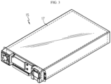
- FIG. 3 is a diagram illustrating the battery module of the battery rack of FIG. 2 .
- the battery rack 10 may include at least one battery module 15.
- this embodiment is described based on the plurality of battery modules 15 stacked upon one another along the heightwise direction of the battery rack 10.
- the plurality of battery modules 15 may include at least one battery cell 17.
- this embodiment is described based on the plurality of battery cells 17 stacked and electrically connected to each other.
- the plurality of battery cells 17 may include lithium ion batteries.
- the plurality of battery cells 17 may include secondary batteries, for example, pouch-type secondary batteries, cylindrical secondary batteries or prismatic secondary batteries.
- this embodiment is described based on that the plurality of battery cells 17 includes pouch-type secondary batteries.
- the anti-explosion housing 50 may hermetically receive the at least one battery rack 10, in this embodiment, the plurality of battery racks 10 by hermetically covering the at least one battery rack 10 or the plurality of battery racks 10.
- the anti-explosion housing 50 may be configured to withstand the fires or explosion pressure.
- the anti-explosion housing 50 may include a steel sheet to withstand the explosion pressure.
- a predetermined thickness of the steel sheet may be designed considering the Safety Factor of between 1.2 and 2.0. Specifically, the predetermined thickness may be at least 200 mm considering the Safety Factor.
- the anti-explosion housing 50 may include a galvanized steel sheet. Additionally, the anti-explosion housing 50 may include an electrogalvanized steel sheet.
- anti-explosion housing 50 will be described in more detail.
- FIG. 4 is an exploded perspective view of the anti-explosion housing of the energy storage system of FIG. 1
- FIG. 5 is a diagram illustrating a base plate of the anti-explosion housing of FIG. 4 .
- the anti-explosion housing 50 may include a bottom cover 100, side covers 200, 300, door units 400, 500, a rear cover 600 and a top cover 700.
- the bottom cover 100 may cover the bottom of the at least one battery rack 10, in this embodiment, the plurality of battery racks 10.
- the bottom cover 100 may have a sufficient size to cover the bottom of the plurality of battery racks 10, and may include the steel sheet.
- the bottom cover 100 may include a galvanized steel sheet or an electrogalvanized steel sheet.
- the pair of side covers 200, 300 may be provided and coupled to the bottom cover 100, and may cover two sides of the at least one battery rack 10, in this embodiment, the plurality of battery racks 10.
- the side covers 200, 300 may include the first side cover 200 and the second side cover 300.
- the first side cover 200 may cover one side of the at least one battery rack 10, in this embodiment, the plurality of battery racks 10.
- the first side cover 200 may include side panels 210, 220, 230 and a thermal insulation panel 250.
- the plurality of side panels 210, 220, 230 may be provided and may include a steel sheet. Furthermore, the plurality of side panels 210, 220, 230 may include a galvanized steel sheet or an electrogalvanized steel sheet. The plurality of side panels 210, 220, 230 may be stacked and connected to each other in the lateral direction of the anti-explosion housing 50.
- the thermal insulation panel 250 may be positioned facing one side of the at least one battery rack 10, in this embodiment, the plurality of battery racks 10. Specifically, the thermal insulation panel 250 may be positioned between one side of the plurality of battery racks 10 and the side panel 230.
- the thermal insulation panel 250 may include an insulating material of a predetermined thickness, for example, glass wool or superwool, to prevent heat transfer.
- a predetermined thickness for example, glass wool or superwool
- this embodiment is described based on the thermal insulation panel 250 including superwool of at least 100 mm.
- the second side cover 300 may be positioned opposite the first side cover 200, and may cover the other side of the at least one battery rack 10, in this embodiment, the plurality of battery racks 10.
- the second side cover 30 may include side panels 310, 320, 330 and a thermal insulation panel 350.
- the plurality of side panels 310, 320, 330 may be provided and may include a steel sheet. Furthermore, the plurality of side panels 310, 320, 330 may include a galvanized steel sheet or an electrogalvanized steel sheet. The plurality of side panels 310, 320, 330 may be stacked and connected to each other in the lateral direction of the anti-explosion housing 50.
- the thermal insulation panel 350 may be positioned facing the other side of the at least one battery rack 10, in this embodiment, the plurality of battery racks 10. Specifically, the thermal insulation panel 350 may be positioned between the other side of the plurality of battery racks 10 and the side panel 330.
- the thermal insulation panel 350 may include an insulating material of a predetermined thickness, for example, glass wool or superwool, to prevent heat transfer.
- a predetermined thickness for example, glass wool or superwool
- this embodiment is described based on the thermal insulation panel 350 including superwool of at least 100 mm.
- the door units 400, 500 may be coupled to the pair of side covers 200, 300, and may be open/closed on the front side of the at least one battery rack 10, in this embodiment, the plurality of battery racks 10. Through the opening/closing of the door units 400, 500, it is possible to increase the operator's work efficiency in the management or investigation of the at least one battery rack 10.
- the door units 400, 500 may be pivotaly hinge-connected from the pair of side covers 200, 300.
- the pair of door units 400, 500 may be provided and connected to the side covers 200, 300, respectively.
- the pair of door units 400, 500 may include the first door 400 and the second door 500.
- the first door 400 may be pivotably hinge-connected to the first side cover 200.
- the first door 400 may include a locking unit that is locked or unlocked by user manipulation or automatic control when the door 400 is closed.
- the first door 400 may include a steel sheet. Furthermore, the first door 400 may include a galvanized steel sheet or an electrogalvanized steel sheet.
- the second door 500 may be pivotably hinge-connected to the second side cover 30.
- the second door 500 and the first door 400 may be hermetically coupled to each other when the door units 400, 500 are closed.
- the second door 500 may include a locking unit that is locked or unlocked by user manipulation or automatic control when the door 500 is closed.
- the second door 500 may include a steel sheet. Furthermore, the second door 500 may include a galvanized steel sheet or an electrogalvanized steel sheet.
- the rear cover 600 may be provided on the rear side of the door units 400, 500 to cover the rear side of the at least one battery rack 10, in this embodiment, the plurality of battery racks 10.
- the rear cover 600 may include rear panels 610, 620 and an air conditioning unit 650.
- the rear panels 610, 620 may be positioned facing the rear side of the at least one battery rack 10, in this embodiment, the plurality of battery racks 10.
- the plurality of rear panels 610, 620 may be provided and stacked along the front-rear direction of the anti-explosion housing 50.
- the plurality of rear panels 610, 620 may include a steel sheet. Furthermore, the plurality of rear panels 610, 620 may include a galvanized steel sheet or an electrogalvanized steel sheet.
- the air conditioning unit 650 may be configured to control an amount of heat generated from the at least one battery rack 10, in this embodiment, the plurality of battery racks 10, and may be provided in the at least one rear panel 610, 620.
- the air conditioning unit 650 may detect heat or smoke generated from the at least one battery rack 10 and stop the operation of the at least one battery rack 10.
- the top cover 700 may be provided on the rear cover 600 and the door units 400, 500 to cover the top of the at least one battery rack 10, in this embodiment, the plurality of battery racks 10.
- the top cover 700 may include at least one gas outlet 750 (see FIG. 7 ) to force internal gas out.
- the top cover 700 may include a steel sheet. Furthermore, the top cover 700 may include a galvanized steel sheet or an electrogalvanized steel sheet.
- the top cover 700 may be coupled to the side covers 300, 400 and the rear cover 600.
- the top cover 700 may be flange joined to the side covers 300, 400 and the rear cover 600, and when flange joined, the at least one gas outlet 750 may be additionally formed on top of the top cover 700.
- the flange joint may be carried out in the coupling between the bottom cover 100, the side covers 300, 400 and the rear cover 600.
- the bottom cover 100 may have a gas outlet.
- a flame passage may be formed through the formation of the gas outlet via the flange joint, and when flames or explosions of the battery rack 10 in the anti-explosion housing 50 occur, high temperature and high pressure internal gas G (see FIG. 7 ) may be forced out of the anti-explosion housing 50, thereby effectively reducing the internal pressure of the anti-explosion housing 50.
- the anti-explosion housing 50 may further include the base plate 800.
- the base plate 800 may support the bottom of the bottom cover 100.
- the base plate 800 may include a conveyance guider 820 and a reinforcement rib 850.
- the conveyance guider 820 may be provided on at least one side of the base plate 800 to guide the conveyance of the base plate 800 and the conveyance of the entire anti-explosion housing 50 or the energy storage system 1.
- the reinforcement rib 850 may be provided on the upper surface of the base plate 800 to reinforce the strength of the base plate 800. At least one reinforcement rib 850 may be provided. Hereinafter, this embodiment is described based on the plurality of reinforcement ribs 850.
- the anti-explosion housing 50 may further include a guide pole 900.
- At least one guide pole 900 may be provided. Hereinafter, this embodiment is described based on the plurality of guide poles 900.
- the plurality of guide poles 900 may be provided between the door units 400, 500 and the rear cover 600 to guide the support of the at least one battery rack 10.
- the plurality of guide poles 900 may be spaced a predetermined distance apart from each other in the front-rear direction of the anti-explosion housing 50.
- the anti-explosion housing 50 may further include a sealing gasket 950.
- the sealing gasket 950 may be positioned on the rear side of the door units 400, 500, to enhance the salability of the edge area of the door units 400, 500 when the door units 400, 500 are closed.
- FIGS. 6 and 7 are diagrams illustrating the mechanism for ensuring safety through the anti-explosion housing when the abnormal situation occurs in the energy storage system of FIG. 1 .
- the abnormal situation may occur due to overheat in at least one of the plurality of battery racks 10 of the energy storage system 1.
- fires in the battery rack 10 or even explosions of the battery rack 10 may occur depending on the degree of overheat.
- the anti-explosion housing 50 including the steel sheet is configured to seal up the plurality of battery racks 10, and in the event of the fires or explosions, the anti-explosion housing 50 may withstand the explosion pressure of the battery rack 10, thereby preventing the risk of additional explosion propagation out of the anti-explosion housing 50.
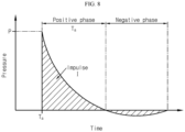
- FIG. 8 is a graph illustrating the calculation of the explosion pressure related to the anti-explosion housing of the energy storage system of FIG. 1 .
- the simulation conditions for explosion pressure calculation are as follows.
- the analysis method uses transient analysis, and a linear elasticity model having high accuracy in the elastic range is applied.
- C denotes the damping coefficient
- M denotes the mass
- K denotes the stiffness
- the mesh is applied in the cell size of approximately 0.0075 m, and the number of cells of 5,557,725 EA.
- the blast load is divided into a positive phase in which the pressure is higher than the atmospheric pressure and a negative phase in which the pressure is lower than the atmospheric pressure, and when a shock wave reaches, the positive pressure greatly increases instantaneously and subsequently, the magnitude of the positive pressure decreases fast. Subsequently, the negative pressure follows until the pressure equals the ambient atmospheric pressure. However, in general, since the influence of the negative phase is negligibly small in the explosion analysis, only the positive phase is considered. Furthermore, as the hydrogen concentration is higher or the pressure vessel is smaller, higher pressure is applied.
- the blast load may be calculated, considering FIG. 8 and the following equations.
- the blast load is calculated using the scaled distance as the key variable.
- Z R W 1 / 3
- Equation 1 Z denotes the scaled distance, R denotes the distance from the explosive to the object, and W denotes the amount of the explosive.
- the pressure of the blast load is calculated as the sum of the incident pressure and the reflected pressure, and the maximum value of the positive pressure considering the incident angle is as follows.
- P max P inc X 1 + cos ⁇ ⁇ 2 cos 2 ⁇ + P ref X cos 2 ⁇
- P max is the maximum positive pressure
- P inc is the maximum the incident pressure
- P ref is the maximum the reflected pressure
- the total impulse of the blast load may be calculated by the same method as the maximum positive pressure.
- I max I inc X 1 + cos ⁇ ⁇ 2 cos 2 ⁇ + I ref X cos 2 ⁇
- I max is the total impulse
- I inc is the total incident pressure impulse
- I ref is the total reflected pressure impulse
- T 0 2 XI max P max
- T 0 is the positive pressure duration
- P max is the maximum positive pressure
- I max is the total impulse.
- t is the time after the explosion occurred
- P max is the maximum positive pressure
- T a is the positive pressure arrival time
- T 0 is the positive pressure duration.
- FIG. 9 is a graph illustrating the calculation of the explosion pressure applied to the inner wall of the anti-explosion housing of the energy storage system of FIG. 1 .
- the explosion pressure calculation conditions are as follows. Assume that the shortest distance from the explosive to the object is 0.84 m, the amount of the explosive is 0.59 kg, and the incident angle of the explosion pressure onto the wall surface is 0° perpendicular to the surface. Furthermore, the time step is as follows. T a ⁇ Time ⁇ T a + T 0 : 0.005 ms , Time > T a + T 0 : 0.1 ms ,
- the maximum explosion pressure applied to the wall is 5.01 MPa
- the positive pressure arrival time T a is 0.45 ms
- the positive pressure duration T 0 is 0.19 ms.
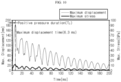
- FIG. 10 is a graph illustrating the calculation of the maximum displacement and the maximum stress applied to the inner wall of the anti-explosion housing of the energy storage system of FIG. 1 .
- the steel sheet of the anti-explosion housing is 1.6 mm in thickness.
- T 0 the positive pressure duration
- T 0 the impulse form explosion pressure occurs, and the maximum displacement is changed up to 183 mm by the explosion pressure, and the displacement is reduced by vibration attenuation and converges to 0 mm.
- the maximum stress is 12.0 GPa that is 69 times greater than the yield stress (175 MPa).
- the peak displacement and stress occurs near the door of the anti-explosion housing at the maximum displacement time (6.3 ms).
- FIGS. 11 and 12 are graphs illustrating the calculation of the maximum stress and the maximum displacement vs thickness of the anti-explosion housing of the energy storage system of FIG. 1 . Specifically, FIGS. 11 and 12 show the test results related to the maximum stress and the maximum displacement with varying thickness of the steel sheet of the anti-explosion housing.
- the test is conducted using the steel sheet with varying thickness.
- an electrogalvanized steel sheet SECC
- SECC electrogalvanized steel sheet
- the thickness varies, for example, 1.6 mm, 10 mm, 20 mm, 30 mm, 40 mm, 100 mm, 200 mm for each steel sheet.
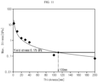
- the maximum displacement and the maximum stress of the anti-explosion housing decreases. Additionally, it can be seen that the minimum thickness of SECC at which the maximum stress does not exceed the yield stress (0.175 GPa) is 109 mm, and when the minimum thickness is applied, the maximum displacement is 0.5 mm.
- the safety factor is a value set by the designer before the design in accordance with the safety requirement of the structure, and in the case of machinery, a value between 1.2 and 2.0 is usually used.
- the final thickness of the steel sheet may be 218 mm that is obtained by multiplying 109 mm by the safety factor 2.0.
- the steel sheet of approximately 200 mm or more is applied to the anti-explosion housing, it is possible to achieve the internal pressure explosion proof design of the anti-explosion housing of the energy storage system. Accordingly, in this embodiment, the steel sheet of approximately 200 mm or more is applied to the anti-explosion housing, it is possible to significantly increase the internal pressure explosion proof performance of the anti-explosion housing.
Landscapes
- Chemical & Material Sciences (AREA)
- Chemical Kinetics & Catalysis (AREA)
- Electrochemistry (AREA)
- General Chemical & Material Sciences (AREA)
- Engineering & Computer Science (AREA)
- Manufacturing & Machinery (AREA)
- Inorganic Chemistry (AREA)
- Battery Mounting, Suspending (AREA)
Abstract
Description
- The present disclosure relates to an energy storage system.
- The present application claims priority to
Korean Patent Application No. 10-2021-0039191 filed on March 25, 2021 - Due to their characteristics of being easily applicable to various products and electrical properties such as high energy density, secondary batteries are not only commonly applied to portable devices, but universally applied to electric vehicles (EVs) or hybrid electric vehicles (HEVs) that are driven by an electrical driving source. Such secondary batteries are gaining attention for their primary advantage of remarkably reducing the use of fossil fuels and not generating by-products from the use of energy, making it a new eco-friendly and energy efficient source of energy.
- The types of secondary batteries widely used at present include lithium ion batteries, lithium polymer batteries, nickel cadmium batteries, nickel hydrogen batteries, nickel zinc batteries or the like. This unit secondary battery cell, i.e., a unit battery cell has an operating voltage of about 2.5V to 4.5V. Accordingly, when a higher output voltage is required, a plurality of battery cells may be connected in series to form a battery pack. Additionally, the battery pack may be fabricated by connecting the plurality of battery cells in parallel according to the charge/discharge capacity required for the battery pack. Accordingly, the number of battery cells included in the battery pack may be variously set depending on the required output voltage or charge/discharge capacity.
- Meanwhile, when fabricating the battery pack by connecting the plurality of battery cells in series/in parallel, it is general to make a battery module including at least one battery cell, and then fabricate a battery pack or a battery rack using at least one battery module with an addition of any other component. Meanwhile, an energy storage system includes at least one battery rack as an energy source.
- In general, the conventional energy storage system includes a plurality of battery racks. Here, the plurality of battery racks includes a plurality of battery modules stacked upon one another, each including at least one battery cell, and a rack case accommodating the plurality of battery cells.
- In the case of the conventional energy storage system, there are risks of fires in the battery rack or even explosions of the battery rack due to defects in the battery cell or system. When fires or explosions occur, greater secondary damage may occur.
- Therefore, there is a need for an approach to provide an energy storage system with improved fire or explosion safety of a battery rack.
- Therefore, the present disclosure is directed to providing an energy storage system with improved fire or explosion safety of a battery rack.
- To solve the above-described problem, the present disclosure provides an energy storage system including at least one battery rack; and an anti-explosion housing hermetically accommodating the at least one battery rack.
- The anti-explosion housing may include a steel sheet of a predetermined thickness.
- The anti-explosion housing may include a bottom cover configured to cover a bottom of the at least one battery rack; a pair of side covers coupled to the bottom cover, and configured to cover two sides of the at least one battery rack; a door unit coupled to the pair of side covers, wherein the door unit is open/closed on a front side of the at least one battery rack; a rear cover provided on a rear side of the door unit to cover a rear side of the at least one battery rack; and a top cover provided on the rear cover and the door unit to cover a top of the at least one battery rack.
- The anti-explosion housing may include a base plate to support a bottom of the bottom cover.
- The base plate may include at least one reinforcement rib on an upper surface to reinforce a strength of the base plate.
- The pair of side covers may include a first side cover to cover a side of the at least one battery rack; and a second side cover positioned opposite the first side cover to cover an opposite side of the at least one battery rack.
- Each of the first side cover and the second side cover may include a plurality of side panels stacked upon one another.
- The first side cover and the second side cover may include a thermal insulation panel positioned facing the side of the at least one battery rack.
- The thermal insulation panel may include superwool.
- The door unit may be pivotably hinge-connected from the pair of side covers.
- A pair of the door units may be provided, and each door unit may be connected to each side cover.
- The rear cover may include at least one rear panel positioned facing the rear side of the at least one battery rack; and an air-conditioning unit provided in the at least one rear panel to control an amount of heat generated from the at least one battery rack.
- When an abnormal situation in the at least one battery rack occurs, the air-conditioning unit may detect heat or smoke generated from the at least one battery rack and stop the operation of the at least one battery rack.
- The anti-explosion housing may include at least one guide pole between the door unit and the rear cover to guide the support of the at least one battery rack.
- According to the various embodiments as described above, it is possible to provide an energy storage system with improved fire or explosion safety of a battery rack.
- The accompanying drawings illustrate an exemplary embodiment of the present disclosure and together with the following detailed description, serve to provide further understanding of the technical features of the present disclosure, and thus the present disclosure is not construed as being limited to the drawings.
-
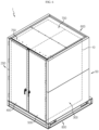
FIG. 1 is a diagram illustrating an energy storage system according to an embodiment of the present disclosure. -
FIG. 2 is a diagram illustrating a battery rack of the energy storage system ofFIG. 1 . -
FIG. 3 is a diagram illustrating a battery module of the battery rack ofFIG. 2 . -
FIG. 4 is an exploded perspective view of an anti-explosion housing of the energy storage system ofFIG. 1 . -
FIG. 5 is a diagram illustrating a base plate of the anti-explosion housing ofFIG. 4 . -
FIGS. 6 and7 are diagrams illustrating the mechanism for ensuring safety through an anti-explosion housing when an abnormal situation occurs in the energy storage system ofFIG. 1 . -
FIG. 8 is a graph illustrating the calculation of the explosion pressure related to an anti-explosion housing of the energy storage system ofFIG. 1 . -
FIG. 9 is a graph illustrating the calculation of the explosion pressure applied to an inner wall of an anti-explosion housing of the energy storage system ofFIG. 1 . -
FIG. 10 is a graph illustrating the calculation of the maximum displacement and the maximum stress applied to an inner wall of an anti-explosion housing of the energy storage system ofFIG. 1 . -
FIGS. 11 and12 are graphs illustrating the calculation of the maximum stress and the maximum displacement vs thickness of an anti-explosion housing of the energy storage system ofFIG. 1 . - The present disclosure will become apparent by describing exemplary embodiments of the present disclosure in detail with reference to the accompanying drawings. The disclosed embodiments are provided by way of illustration to help the understanding of the present disclosure, and it should be understood that the present disclosure may be embodied in many other forms. Additionally, to help the understanding of the present disclosure, the accompanying drawings may show some elements in the exaggerated size, not in the actual size.
-
FIG. 1 is a diagram illustrating an energy storage system according to an embodiment of the present disclosure. - Referring to
FIG. 1 , theenergy storage system 1 may be used as a domestic or industrial energy source. Theenergy storage system 1 may include abattery rack 10 and ananti-explosion housing 50. - The
energy storage system 1 may include at least onebattery rack 10 as an energy source of theenergy storage system 1. Hereinafter, this embodiment is described based on the plurality of battery racks 10. - Hereinafter, the
battery rack 10 will be described in more detail. -
FIG. 2 is a diagram illustrating the battery rack of the energy storage system ofFIG. 1 , andFIG. 3 is a diagram illustrating the battery module of the battery rack ofFIG. 2 . - Referring to
FIGS. 2 and3 , thebattery rack 10 may include at least onebattery module 15. Hereinafter, this embodiment is described based on the plurality ofbattery modules 15 stacked upon one another along the heightwise direction of thebattery rack 10. - The plurality of
battery modules 15 may include at least onebattery cell 17. Hereinafter, this embodiment is described based on the plurality ofbattery cells 17 stacked and electrically connected to each other. - The plurality of
battery cells 17 may include lithium ion batteries. Specifically, the plurality ofbattery cells 17 may include secondary batteries, for example, pouch-type secondary batteries, cylindrical secondary batteries or prismatic secondary batteries. Hereinafter, this embodiment is described based on that the plurality ofbattery cells 17 includes pouch-type secondary batteries. - Referring back to
FIG. 1 , theanti-explosion housing 50 may hermetically receive the at least onebattery rack 10, in this embodiment, the plurality ofbattery racks 10 by hermetically covering the at least onebattery rack 10 or the plurality of battery racks 10. - In the event of fires caused by abnormal situations in the plurality of
battery racks 10, and further, dangerous situations, for example, explosions of thebattery rack 10, theanti-explosion housing 50 may be configured to withstand the fires or explosion pressure. - To this end, the
anti-explosion housing 50 may include a steel sheet to withstand the explosion pressure. Here, a predetermined thickness of the steel sheet may be designed considering the Safety Factor of between 1.2 and 2.0. Specifically, the predetermined thickness may be at least 200 mm considering the Safety Factor. - Furthermore, the
anti-explosion housing 50 may include a galvanized steel sheet. Additionally, theanti-explosion housing 50 may include an electrogalvanized steel sheet. - Hereinafter, the
anti-explosion housing 50 will be described in more detail. -
FIG. 4 is an exploded perspective view of the anti-explosion housing of the energy storage system ofFIG. 1 , andFIG. 5 is a diagram illustrating a base plate of the anti-explosion housing ofFIG. 4 . - Referring to
FIGS. 1 ,4 and5 , theanti-explosion housing 50 may include abottom cover 100, side covers 200, 300,door units rear cover 600 and atop cover 700. - The
bottom cover 100 may cover the bottom of the at least onebattery rack 10, in this embodiment, the plurality of battery racks 10. Thebottom cover 100 may have a sufficient size to cover the bottom of the plurality ofbattery racks 10, and may include the steel sheet. Furthermore, thebottom cover 100 may include a galvanized steel sheet or an electrogalvanized steel sheet. - The pair of side covers 200, 300 may be provided and coupled to the
bottom cover 100, and may cover two sides of the at least onebattery rack 10, in this embodiment, the plurality of battery racks 10. - The side covers 200, 300 may include the
first side cover 200 and thesecond side cover 300. - The
first side cover 200 may cover one side of the at least onebattery rack 10, in this embodiment, the plurality of battery racks 10. - The
first side cover 200 may includeside panels thermal insulation panel 250. - The plurality of
side panels side panels side panels anti-explosion housing 50. - The
thermal insulation panel 250 may be positioned facing one side of the at least onebattery rack 10, in this embodiment, the plurality of battery racks 10. Specifically, thethermal insulation panel 250 may be positioned between one side of the plurality ofbattery racks 10 and theside panel 230. - The
thermal insulation panel 250 may include an insulating material of a predetermined thickness, for example, glass wool or superwool, to prevent heat transfer. Hereinafter, this embodiment is described based on thethermal insulation panel 250 including superwool of at least 100 mm. - The
second side cover 300 may be positioned opposite thefirst side cover 200, and may cover the other side of the at least onebattery rack 10, in this embodiment, the plurality of battery racks 10. - The
second side cover 30 may includeside panels thermal insulation panel 350. - The plurality of
side panels side panels side panels anti-explosion housing 50. - The
thermal insulation panel 350 may be positioned facing the other side of the at least onebattery rack 10, in this embodiment, the plurality of battery racks 10. Specifically, thethermal insulation panel 350 may be positioned between the other side of the plurality ofbattery racks 10 and theside panel 330. - The
thermal insulation panel 350 may include an insulating material of a predetermined thickness, for example, glass wool or superwool, to prevent heat transfer. Hereinafter, this embodiment is described based on thethermal insulation panel 350 including superwool of at least 100 mm. - The
door units battery rack 10, in this embodiment, the plurality of battery racks 10. Through the opening/closing of thedoor units battery rack 10. - The
door units door units - The pair of
door units first door 400 and thesecond door 500. - The
first door 400 may be pivotably hinge-connected to thefirst side cover 200. Thefirst door 400 may include a locking unit that is locked or unlocked by user manipulation or automatic control when thedoor 400 is closed. - The
first door 400 may include a steel sheet. Furthermore, thefirst door 400 may include a galvanized steel sheet or an electrogalvanized steel sheet. - The
second door 500 may be pivotably hinge-connected to thesecond side cover 30. Thesecond door 500 and thefirst door 400 may be hermetically coupled to each other when thedoor units second door 500 may include a locking unit that is locked or unlocked by user manipulation or automatic control when thedoor 500 is closed. - The
second door 500 may include a steel sheet. Furthermore, thesecond door 500 may include a galvanized steel sheet or an electrogalvanized steel sheet. - The
rear cover 600 may be provided on the rear side of thedoor units battery rack 10, in this embodiment, the plurality of battery racks 10. - The
rear cover 600 may includerear panels air conditioning unit 650. - The
rear panels battery rack 10, in this embodiment, the plurality of battery racks 10. The plurality ofrear panels anti-explosion housing 50. - The plurality of
rear panels rear panels - The
air conditioning unit 650 may be configured to control an amount of heat generated from the at least onebattery rack 10, in this embodiment, the plurality ofbattery racks 10, and may be provided in the at least onerear panel - When an abnormal situation in the at least one
battery rack 10 occurs, theair conditioning unit 650 may detect heat or smoke generated from the at least onebattery rack 10 and stop the operation of the at least onebattery rack 10. - The
top cover 700 may be provided on therear cover 600 and thedoor units battery rack 10, in this embodiment, the plurality of battery racks 10. Thetop cover 700 may include at least one gas outlet 750 (seeFIG. 7 ) to force internal gas out. - The
top cover 700 may include a steel sheet. Furthermore, thetop cover 700 may include a galvanized steel sheet or an electrogalvanized steel sheet. - The
top cover 700 may be coupled to the side covers 300, 400 and therear cover 600. Here, thetop cover 700 may be flange joined to the side covers 300, 400 and therear cover 600, and when flange joined, the at least onegas outlet 750 may be additionally formed on top of thetop cover 700. - The flange joint may be carried out in the coupling between the
bottom cover 100, the side covers 300, 400 and therear cover 600. In this case, thebottom cover 100 may have a gas outlet. In this embodiment, a flame passage may be formed through the formation of the gas outlet via the flange joint, and when flames or explosions of thebattery rack 10 in theanti-explosion housing 50 occur, high temperature and high pressure internal gas G (seeFIG. 7 ) may be forced out of theanti-explosion housing 50, thereby effectively reducing the internal pressure of theanti-explosion housing 50. - The
anti-explosion housing 50 may further include thebase plate 800. - The
base plate 800 may support the bottom of thebottom cover 100. - The
base plate 800 may include aconveyance guider 820 and areinforcement rib 850. - The
conveyance guider 820 may be provided on at least one side of thebase plate 800 to guide the conveyance of thebase plate 800 and the conveyance of the entireanti-explosion housing 50 or theenergy storage system 1. - The
reinforcement rib 850 may be provided on the upper surface of thebase plate 800 to reinforce the strength of thebase plate 800. At least onereinforcement rib 850 may be provided. Hereinafter, this embodiment is described based on the plurality ofreinforcement ribs 850. - The
anti-explosion housing 50 may further include aguide pole 900. - At least one
guide pole 900 may be provided. Hereinafter, this embodiment is described based on the plurality ofguide poles 900. - The plurality of
guide poles 900 may be provided between thedoor units rear cover 600 to guide the support of the at least onebattery rack 10. The plurality ofguide poles 900 may be spaced a predetermined distance apart from each other in the front-rear direction of theanti-explosion housing 50. - Meanwhile, the
anti-explosion housing 50 may further include a sealinggasket 950. - The sealing
gasket 950 may be positioned on the rear side of thedoor units door units door units - Hereinafter, the mechanism for ensuring safety through the
anti-explosion housing 50 when an abnormal situation occurs in theenergy storage system 1 according to this embodiment will be described in more detail. -
FIGS. 6 and7 are diagrams illustrating the mechanism for ensuring safety through the anti-explosion housing when the abnormal situation occurs in the energy storage system ofFIG. 1 . - Referring to
FIGS. 6 and7 , the abnormal situation may occur due to overheat in at least one of the plurality ofbattery racks 10 of theenergy storage system 1. In this instance, fires in thebattery rack 10 or even explosions of thebattery rack 10 may occur depending on the degree of overheat. - In this embodiment, the
anti-explosion housing 50 including the steel sheet is configured to seal up the plurality ofbattery racks 10, and in the event of the fires or explosions, theanti-explosion housing 50 may withstand the explosion pressure of thebattery rack 10, thereby preventing the risk of additional explosion propagation out of theanti-explosion housing 50. - In this instance, since the high temperature and high pressure gas G is effectively forced out through the
gas outlet 750 of theanti-explosion housing 50, it is possible to reduce the internal pressure of theanti-explosion housing 50, reduce the expansion speed of the explosion gas and sufficiently lower the internal temperature, thereby preventing additional secondary explosion risks more effectively. -
FIG. 8 is a graph illustrating the calculation of the explosion pressure related to the anti-explosion housing of the energy storage system ofFIG. 1 . - Referring to
FIG. 8 , first, the simulation conditions for explosion pressure calculation are as follows. The analysis method uses transient analysis, and a linear elasticity model having high accuracy in the elastic range is applied. - Furthermore, Rayleigh Damping Model is applied. Specifically, when vibration occurs in response to impulse in the event of explosion, the damping coefficient which is proportional to the mass and stiffness of the anti-explosion housing is applied. This is defined by the following Equation.

- In the above Equation, C denotes the damping coefficient, M denotes the mass, and K denotes the stiffness.
- Additionally, in the simulation, the mesh is applied in the cell size of approximately 0.0075 m, and the number of cells of 5,557,725 EA.
- Finally, the physical properties of the anti-explosion housing applied in the simulation are as follows.
[Table 1] Part Material Density [Kg/m3] Poisson's Ratio Young's Modulus [GPa] Yield Stress [MPa] Tensile Strength [MPa] Steel sheet SECC 7800 0.29 209 175 365 - The explosion pressure calculation theory is described below.
- The blast load is divided into a positive phase in which the pressure is higher than the atmospheric pressure and a negative phase in which the pressure is lower than the atmospheric pressure, and when a shock wave reaches, the positive pressure greatly increases instantaneously and subsequently, the magnitude of the positive pressure decreases fast. Subsequently, the negative pressure follows until the pressure equals the ambient atmospheric pressure. However, in general, since the influence of the negative phase is negligibly small in the explosion analysis, only the positive phase is considered. Furthermore, as the hydrogen concentration is higher or the pressure vessel is smaller, higher pressure is applied.
- The blast load may be calculated, considering
FIG. 8 and the following equations. - The blast load is calculated using the scaled distance as the key variable.

- In the
above Equation 1, Z denotes the scaled distance, R denotes the distance from the explosive to the object, and W denotes the amount of the explosive. - The pressure of the blast load is calculated as the sum of the incident pressure and the reflected pressure, and the maximum value of the positive pressure considering the incident angle is as follows.

- Pmax is the maximum positive pressure, Pinc is the maximum the incident pressure, and Pref is the maximum the reflected pressure.
- The total impulse of the blast load may be calculated by the same method as the maximum positive pressure.

- Imax is the total impulse, Iinc is the total incident pressure impulse, and Iref is the total reflected pressure impulse.
- The positive pressure duration T0 is as follows.

- T0 is the positive pressure duration, Pmax is the maximum positive pressure, and Imax is the total impulse.
- Considering this, the finally calculated blast load equation is as follows.

- Here, t is the time after the explosion occurred, Pmax is the maximum positive pressure, Ta is the positive pressure arrival time, and T0 is the positive pressure duration.
-
FIG. 9 is a graph illustrating the calculation of the explosion pressure applied to the inner wall of the anti-explosion housing of the energy storage system ofFIG. 1 . - Referring to
FIG. 9 , first, the explosion pressure calculation conditions are as follows. Assume that the shortest distance from the explosive to the object is 0.84 m, the amount of the explosive is 0.59 kg, and the incident angle of the explosion pressure onto the wall surface is 0° perpendicular to the surface. Furthermore, the time step is as follows.

- As a result of calculating the explosion pressure, the maximum explosion pressure applied to the wall is 5.01 MPa, the positive pressure arrival time Ta is 0.45 ms, and the positive pressure duration T0 is 0.19 ms.
-
FIG. 10 is a graph illustrating the calculation of the maximum displacement and the maximum stress applied to the inner wall of the anti-explosion housing of the energy storage system ofFIG. 1 . - Referring to
FIG. 10 , first, in the test, the steel sheet of the anti-explosion housing is 1.6 mm in thickness. During the positive pressure duration T0, the impulse form explosion pressure occurs, and the maximum displacement is changed up to 183 mm by the explosion pressure, and the displacement is reduced by vibration attenuation and converges to 0 mm. It can be seen that the maximum stress is 12.0 GPa that is 69 times greater than the yield stress (175 MPa). Furthermore, the peak displacement and stress occurs near the door of the anti-explosion housing at the maximum displacement time (6.3 ms). -
FIGS. 11 and12 are graphs illustrating the calculation of the maximum stress and the maximum displacement vs thickness of the anti-explosion housing of the energy storage system ofFIG. 1 . Specifically,FIGS. 11 and12 show the test results related to the maximum stress and the maximum displacement with varying thickness of the steel sheet of the anti-explosion housing. - Referring to
FIGS. 11 and12 , first, the test is conducted using the steel sheet with varying thickness. In the test, an electrogalvanized steel sheet (SECC) is used for the steel sheet, and the thickness varies, for example, 1.6 mm, 10 mm, 20 mm, 30 mm, 40 mm, 100 mm, 200 mm for each steel sheet. - As a result of the test, it can be seen that as the steel sheet increases in thickness, the maximum displacement and the maximum stress of the anti-explosion housing decreases. Additionally, it can be seen that the minimum thickness of SECC at which the maximum stress does not exceed the yield stress (0.175 GPa) is 109 mm, and when the minimum thickness is applied, the maximum displacement is 0.5 mm.
- Meanwhile, it is desirable to apply the safety factor in the selection of the final thickness. As noted above, the safety factor is a value set by the designer before the design in accordance with the safety requirement of the structure, and in the case of machinery, a value between 1.2 and 2.0 is usually used. When the safety factor 2.0 is applied to ensure greater safety, the final thickness of the steel sheet may be 218 mm that is obtained by multiplying 109 mm by the safety factor 2.0.
- It can be seen through the above-described simulation that when the steel sheet of approximately 200 mm or more is applied to the anti-explosion housing, it is possible to achieve the internal pressure explosion proof design of the anti-explosion housing of the energy storage system. Accordingly, in this embodiment, the steel sheet of approximately 200 mm or more is applied to the anti-explosion housing, it is possible to significantly increase the internal pressure explosion proof performance of the anti-explosion housing.
- According to the various embodiments described above, it is possible to provide the
energy storage system 1 with improved fire or explosion safety of thebattery rack 10. - While an exemplary embodiment of the present disclosure has been hereinabove illustrated and described, the present disclosure is not limited to the above-described particular embodiment and it is obvious to those skilled in the art that a variety of modifications and changes may be made thereto without departing from the claimed subject matter of the present disclosure in the appended claims, and such modifications and changes should not be individually understood from the technical aspects or scope of the present disclosure.
Claims (14)
- An energy storage system, comprising:at least one battery rack; andan anti-explosion housing hermetically accommodating the at least one battery rack.
- The energy storage system according to claim 1, wherein the anti-explosion housing includes a steel sheet of a predetermined thickness.
- The energy storage system according to claim 1, wherein the anti-explosion housing includes:a bottom cover configured to cover a bottom of the at least one battery rack;a pair of side covers coupled to the bottom cover, and configured to cover two sides of the at least one battery rack;a door unit coupled to the pair of side covers, wherein the door unit is open/closed on a front side of the at least one battery rack;a rear cover provided on a rear side of the door unit to cover a rear side of the at least one battery rack; anda top cover provided on the rear cover and the door unit to cover a top of the at least one battery rack.
- The energy storage system according to claim 3, wherein the anti-explosion housing includes a base plate to support a bottom of the bottom cover.
- The energy storage system according to claim 4, wherein the base plate includes at least one reinforcement rib on an upper surface to reinforce a strength of the base plate.
- The energy storage system according to claim 3, wherein the pair of side covers include:a first side cover to cover a side of the at least one battery rack; anda second side cover positioned opposite the first side cover to cover an opposite side of the at least one battery rack.
- The energy storage system according to claim 6, wherein each of the first side cover and the second side cover includes a plurality of side panels stacked upon one another.
- The energy storage system according to claim 6, wherein the first side cover and the second side cover include a thermal insulation panel positioned facing the side of the at least one battery rack.
- The energy storage system according to claim 8, wherein the thermal insulation panel includes superwool.
- The energy storage system according to claim 3, wherein the door unit is pivotably hinge-connected from the pair of side covers.
- The energy storage system according to claim 3, wherein a pair of the door units are provided, and each door unit is connected to each side cover.
- The energy storage system according to claim 3, wherein the rear cover includes:at least one rear panel positioned facing the rear side of the at least one battery rack; andan air-conditioning unit provided in the at least one rear panel to control an amount of heat generated from the at least one battery rack.
- The energy storage system according to claim 12, wherein when an abnormal situation in the at least one battery rack occurs, the air-conditioning unit detects heat or smoke generated from the at least one battery rack and stops the operation of the at least one battery rack.
- The energy storage system according to claim 3, wherein the anti-explosion housing includes at least one guide pole between the door unit and the rear cover to guide the support of the at least one battery rack.
Applications Claiming Priority (2)
| Application Number | Priority Date | Filing Date | Title |
|---|---|---|---|
| KR20210039191 | 2021-03-25 | ||
| PCT/KR2022/004096 WO2022203406A1 (en) | 2021-03-25 | 2022-03-23 | Power storage apparatus |
Publications (2)
| Publication Number | Publication Date |
|---|---|
| EP4184681A1 true EP4184681A1 (en) | 2023-05-24 |
| EP4184681A4 EP4184681A4 (en) | 2024-08-07 |
Family
ID=83397706
Family Applications (1)
| Application Number | Title | Priority Date | Filing Date |
|---|---|---|---|
| EP22776106.1A Pending EP4184681A4 (en) | 2021-03-25 | 2022-03-23 | ENERGY STORAGE DEVICE |
Country Status (6)
| Country | Link |
|---|---|
| US (1) | US20230238643A1 (en) |
| EP (1) | EP4184681A4 (en) |
| JP (1) | JP7652886B2 (en) |
| KR (1) | KR20220133804A (en) |
| CN (1) | CN220290972U (en) |
| WO (1) | WO2022203406A1 (en) |
Families Citing this family (5)
| Publication number | Priority date | Publication date | Assignee | Title |
|---|---|---|---|---|
| CN120035904A (en) * | 2022-10-09 | 2025-05-23 | 宁德新能源科技有限公司 | Battery Pack |
| KR102666721B1 (en) * | 2023-08-31 | 2024-05-16 | 이강용 | Battery storage container with seismic structure |
| CN117080619B (en) * | 2023-10-16 | 2023-12-15 | 上海北开科技发展有限公司 | New energy automobile battery heat dissipation management method and system |
| KR20250098766A (en) * | 2023-12-22 | 2025-07-01 | 주식회사 엘지에너지솔루션 | Container module |
| WO2026063426A1 (en) * | 2024-09-20 | 2026-03-26 | 株式会社Gsユアサ | Power storage board |
Family Cites Families (21)
| Publication number | Priority date | Publication date | Assignee | Title |
|---|---|---|---|---|
| JP3128531U (en) | 2006-10-02 | 2007-01-18 | 株式会社マエショウ | Storage battery storage box |
| JP2008170077A (en) | 2007-01-12 | 2008-07-24 | Matsushita Electric Ind Co Ltd | Heating device |
| JP5402426B2 (en) | 2009-09-09 | 2014-01-29 | 株式会社村田製作所 | Battery test equipment, battery transport / storage case |
| KR101303010B1 (en) * | 2011-08-18 | 2013-09-03 | 삼성중공업 주식회사 | Explosion Proof Rack |
| US20130288096A1 (en) * | 2011-09-16 | 2013-10-31 | General Electric Company | Modular battery |
| JP6102541B2 (en) | 2013-06-13 | 2017-03-29 | 住友電気工業株式会社 | Storage device and storage battery replacement method |
| EP3097598B1 (en) * | 2014-01-23 | 2017-07-26 | Spark Racing Technology SAS | Protective battery casing |
| CN104001297B (en) * | 2014-05-21 | 2016-08-24 | 中国南方电网有限责任公司调峰调频发电公司 | A kind of lithium ion battery fire-fighting experiment cabinet carrying automatic alarm and fire extinguishing system |
| JP6657581B2 (en) | 2015-03-30 | 2020-03-04 | 株式会社Gsユアサ | Power storage equipment |
| JP2018536963A (en) * | 2015-09-11 | 2018-12-13 | ユニコス・インコーポレイテッドYounicos, Inc. | Modular storage system |
| CN106848123A (en) * | 2015-12-03 | 2017-06-13 | 重庆益峰新能源装备股份有限公司 | A kind of water-proof type accumulator box |
| CA3021577A1 (en) * | 2016-04-20 | 2017-10-26 | Corvus Energy Inc. | Method and apparatus for managing thermal runaway gases in a battery system |
| JP6722534B2 (en) | 2016-07-21 | 2020-07-15 | 河村電器産業株式会社 | Storage battery cabinet |
| AU2019405440A1 (en) * | 2018-12-17 | 2021-08-12 | Ambri, LLC | High temperature energy storage systems and methods |
| KR102709974B1 (en) * | 2019-07-10 | 2024-09-24 | 주식회사 엘지에너지솔루션 | Battery module, battery rack and energy storage system comprising the battery module |
| KR20210039191A (en) | 2019-10-01 | 2021-04-09 | (주)경성그린에너지 | Heat Recovery System for Boiler |
| CN210778745U (en) * | 2019-11-12 | 2020-06-16 | 深圳未名七号新能源有限公司 | Energy storage device |
| KR102822609B1 (en) * | 2019-11-14 | 2025-06-18 | 주식회사 엘지에너지솔루션 | Battery Rack |
| KR102191291B1 (en) * | 2020-03-12 | 2020-12-16 | 인셀(주) | Battery enclosure for fire spread prevention, deflagration prevention and efficient cooling and inner space having it |
| CN111416083A (en) * | 2020-04-22 | 2020-07-14 | 深圳安易控新能源科技有限公司 | A lithium-ion battery holder with dual pipes |
| CN112259894B (en) | 2020-09-14 | 2022-11-18 | 广州智光储能科技有限公司 | High-voltage lithium battery energy storage temperature equalizing system |
-
2022
- 2022-03-23 WO PCT/KR2022/004096 patent/WO2022203406A1/en not_active Ceased
- 2022-03-23 US US18/007,649 patent/US20230238643A1/en active Pending
- 2022-03-23 KR KR1020220036251A patent/KR20220133804A/en active Pending
- 2022-03-23 JP JP2023509813A patent/JP7652886B2/en active Active
- 2022-03-23 EP EP22776106.1A patent/EP4184681A4/en active Pending
- 2022-03-23 CN CN202290000180.1U patent/CN220290972U/en active Active
Also Published As
| Publication number | Publication date |
|---|---|
| KR20220133804A (en) | 2022-10-05 |
| US20230238643A1 (en) | 2023-07-27 |
| WO2022203406A1 (en) | 2022-09-29 |
| CN220290972U (en) | 2024-01-02 |
| JP7652886B2 (en) | 2025-03-27 |
| JP2023538319A (en) | 2023-09-07 |
| EP4184681A4 (en) | 2024-08-07 |
Similar Documents
| Publication | Publication Date | Title |
|---|---|---|
| US20230238643A1 (en) | Power storage apparatus | |
| CN115088122B (en) | Battery module with partition walls and insulation for fire suppression | |
| EP3840082B1 (en) | Battery module, battery rack comprising same and power storage device | |
| KR102830526B1 (en) | Battery Module Having Pocket For Collecting Flare and Spark | |
| US20230128563A1 (en) | Battery module having pocket capable of capturing flare and spark ejected during swelling | |
| EP3528307A1 (en) | Battery module, battery pack comprising same, and power storage apparatus | |
| CN114982055B (en) | Battery module, battery pack including the battery module, and vehicle including the battery pack | |
| KR20170095165A (en) | Accommodation structure of cell module assembly improved in safety | |
| JP5151715B2 (en) | Fuel cell | |
| KR102813264B1 (en) | Battery Module Having Pocket For Collecting Flare and Spark | |
| US20240006706A1 (en) | Battery module for preventing thermal runaway propagation | |
| US20240204319A1 (en) | Battery module | |
| EP4322293A1 (en) | Battery module, battery pack comprising battery module, and energy storage device and vehicle comprising battery pack | |
| US20250349960A1 (en) | Pad, Battery Module Including the Same, and Battery Pack | |
| EP4343947A1 (en) | Battery module | |
| AU2020246793B2 (en) | Battery module, battery rack comprising same and power storage device | |
| KR102965191B1 (en) | Chamber for testing a thermal propagation | |
| KR20260037923A (en) | A gasket for a battery pack, and a battery pack and a vehicle including the same | |
| KR20230016532A (en) | Battery module, battery pack and vehicle comprising the battery module | |
| JP2026029231A (en) | Power storage device | |
| CN119725903A (en) | Single battery, battery pack and power-consuming device | |
| CN119725902A (en) | Single battery, battery pack and power-consuming device | |
| KR20260020745A (en) | Battery pack |
Legal Events
| Date | Code | Title | Description |
|---|---|---|---|
| STAA | Information on the status of an ep patent application or granted ep patent |
Free format text: STATUS: THE INTERNATIONAL PUBLICATION HAS BEEN MADE |
|
| PUAI | Public reference made under article 153(3) epc to a published international application that has entered the european phase |
Free format text: ORIGINAL CODE: 0009012 |
|
| STAA | Information on the status of an ep patent application or granted ep patent |
Free format text: STATUS: REQUEST FOR EXAMINATION WAS MADE |
|
| 17P | Request for examination filed |
Effective date: 20230216 |
|
| AK | Designated contracting states |
Kind code of ref document: A1 Designated state(s): AL AT BE BG CH CY CZ DE DK EE ES FI FR GB GR HR HU IE IS IT LI LT LU LV MC MK MT NL NO PL PT RO RS SE SI SK SM TR |
|
| DAV | Request for validation of the european patent (deleted) | ||
| DAX | Request for extension of the european patent (deleted) | ||
| A4 | Supplementary search report drawn up and despatched |
Effective date: 20240703 |
|
| RIC1 | Information provided on ipc code assigned before grant |
Ipc: H01M 50/244 20210101ALI20240628BHEP Ipc: H01M 50/204 20210101ALI20240628BHEP Ipc: H01M 10/48 20060101ALI20240628BHEP Ipc: H01M 10/627 20140101ALI20240628BHEP Ipc: H01M 10/63 20140101ALI20240628BHEP Ipc: H01M 10/663 20140101ALI20240628BHEP Ipc: H01M 10/658 20140101ALI20240628BHEP Ipc: H01M 50/224 20210101ALI20240628BHEP Ipc: H01M 50/251 20210101ALI20240628BHEP Ipc: H01M 50/24 20210101AFI20240628BHEP |