EP4184680A1 - Bloc-batterie, et dispositif de fabrication et procédé de fabrication pour bloc-batterie - Google Patents
Bloc-batterie, et dispositif de fabrication et procédé de fabrication pour bloc-batterie Download PDFInfo
- Publication number
- EP4184680A1 EP4184680A1 EP22736943.6A EP22736943A EP4184680A1 EP 4184680 A1 EP4184680 A1 EP 4184680A1 EP 22736943 A EP22736943 A EP 22736943A EP 4184680 A1 EP4184680 A1 EP 4184680A1
- Authority
- EP
- European Patent Office
- Prior art keywords
- resin
- battery cells
- frame
- battery pack
- manufacturing
- Prior art date
- Legal status (The legal status is an assumption and is not a legal conclusion. Google has not performed a legal analysis and makes no representation as to the accuracy of the status listed.)
- Pending
Links
- 238000004519 manufacturing process Methods 0.000 title claims description 49
- 229920005989 resin Polymers 0.000 claims abstract description 133
- 239000011347 resin Substances 0.000 claims abstract description 133
- 238000004382 potting Methods 0.000 claims abstract description 24
- 238000002347 injection Methods 0.000 claims description 59
- 239000007924 injection Substances 0.000 claims description 59
- 230000004308 accommodation Effects 0.000 claims description 35
- 238000000034 method Methods 0.000 claims description 17
- 229920002050 silicone resin Polymers 0.000 claims description 5
- 238000003780 insertion Methods 0.000 description 12
- 230000037431 insertion Effects 0.000 description 12
- 238000010586 diagram Methods 0.000 description 8
- 230000008901 benefit Effects 0.000 description 3
- 238000012986 modification Methods 0.000 description 3
- 230000004048 modification Effects 0.000 description 3
- 230000003685 thermal hair damage Effects 0.000 description 3
- PXHVJJICTQNCMI-UHFFFAOYSA-N Nickel Chemical compound [Ni] PXHVJJICTQNCMI-UHFFFAOYSA-N 0.000 description 2
- 239000000446 fuel Substances 0.000 description 2
- UFHFLCQGNIYNRP-UHFFFAOYSA-N Hydrogen Chemical compound [H][H] UFHFLCQGNIYNRP-UHFFFAOYSA-N 0.000 description 1
- WHXSMMKQMYFTQS-UHFFFAOYSA-N Lithium Chemical compound [Li] WHXSMMKQMYFTQS-UHFFFAOYSA-N 0.000 description 1
- HBBGRARXTFLTSG-UHFFFAOYSA-N Lithium ion Chemical compound [Li+] HBBGRARXTFLTSG-UHFFFAOYSA-N 0.000 description 1
- 241000156302 Porcine hemagglutinating encephalomyelitis virus Species 0.000 description 1
- 238000013459 approach Methods 0.000 description 1
- 239000006227 byproduct Substances 0.000 description 1
- OJIJEKBXJYRIBZ-UHFFFAOYSA-N cadmium nickel Chemical compound [Ni].[Cd] OJIJEKBXJYRIBZ-UHFFFAOYSA-N 0.000 description 1
- 238000001816 cooling Methods 0.000 description 1
- 238000013461 design Methods 0.000 description 1
- 230000000694 effects Effects 0.000 description 1
- 238000004146 energy storage Methods 0.000 description 1
- 239000002803 fossil fuel Substances 0.000 description 1
- 230000017525 heat dissipation Effects 0.000 description 1
- 229910052739 hydrogen Inorganic materials 0.000 description 1
- 239000001257 hydrogen Substances 0.000 description 1
- 229910052744 lithium Inorganic materials 0.000 description 1
- 229910001416 lithium ion Inorganic materials 0.000 description 1
- 239000000463 material Substances 0.000 description 1
- 229910052759 nickel Inorganic materials 0.000 description 1
- QELJHCBNGDEXLD-UHFFFAOYSA-N nickel zinc Chemical compound [Ni].[Zn] QELJHCBNGDEXLD-UHFFFAOYSA-N 0.000 description 1
- 229920000642 polymer Polymers 0.000 description 1
- 239000000047 product Substances 0.000 description 1
- 239000000243 solution Substances 0.000 description 1
- XLYOFNOQVPJJNP-UHFFFAOYSA-N water Substances O XLYOFNOQVPJJNP-UHFFFAOYSA-N 0.000 description 1
Images


Classifications
-
- H—ELECTRICITY
- H01—ELECTRIC ELEMENTS
- H01M—PROCESSES OR MEANS, e.g. BATTERIES, FOR THE DIRECT CONVERSION OF CHEMICAL ENERGY INTO ELECTRICAL ENERGY
- H01M50/00—Constructional details or processes of manufacture of the non-active parts of electrochemical cells other than fuel cells, e.g. hybrid cells
- H01M50/20—Mountings; Secondary casings or frames; Racks, modules or packs; Suspension devices; Shock absorbers; Transport or carrying devices; Holders
- H01M50/249—Mountings; Secondary casings or frames; Racks, modules or packs; Suspension devices; Shock absorbers; Transport or carrying devices; Holders specially adapted for aircraft or vehicles, e.g. cars or trains
-
- B—PERFORMING OPERATIONS; TRANSPORTING
- B29—WORKING OF PLASTICS; WORKING OF SUBSTANCES IN A PLASTIC STATE IN GENERAL
- B29C—SHAPING OR JOINING OF PLASTICS; SHAPING OF MATERIAL IN A PLASTIC STATE, NOT OTHERWISE PROVIDED FOR; AFTER-TREATMENT OF THE SHAPED PRODUCTS, e.g. REPAIRING
- B29C45/00—Injection moulding, i.e. forcing the required volume of moulding material through a nozzle into a closed mould; Apparatus therefor
- B29C45/14—Injection moulding, i.e. forcing the required volume of moulding material through a nozzle into a closed mould; Apparatus therefor incorporating preformed parts or layers, e.g. injection moulding around inserts or for coating articles
- B29C45/14065—Positioning or centering articles in the mould
-
- H—ELECTRICITY
- H01—ELECTRIC ELEMENTS
- H01M—PROCESSES OR MEANS, e.g. BATTERIES, FOR THE DIRECT CONVERSION OF CHEMICAL ENERGY INTO ELECTRICAL ENERGY
- H01M50/00—Constructional details or processes of manufacture of the non-active parts of electrochemical cells other than fuel cells, e.g. hybrid cells
- H01M50/20—Mountings; Secondary casings or frames; Racks, modules or packs; Suspension devices; Shock absorbers; Transport or carrying devices; Holders
- H01M50/233—Mountings; Secondary casings or frames; Racks, modules or packs; Suspension devices; Shock absorbers; Transport or carrying devices; Holders characterised by physical properties of casings or racks, e.g. dimensions
- H01M50/24—Mountings; Secondary casings or frames; Racks, modules or packs; Suspension devices; Shock absorbers; Transport or carrying devices; Holders characterised by physical properties of casings or racks, e.g. dimensions adapted for protecting batteries from their environment, e.g. from corrosion
-
- B—PERFORMING OPERATIONS; TRANSPORTING
- B29—WORKING OF PLASTICS; WORKING OF SUBSTANCES IN A PLASTIC STATE IN GENERAL
- B29C—SHAPING OR JOINING OF PLASTICS; SHAPING OF MATERIAL IN A PLASTIC STATE, NOT OTHERWISE PROVIDED FOR; AFTER-TREATMENT OF THE SHAPED PRODUCTS, e.g. REPAIRING
- B29C33/00—Moulds or cores; Details thereof or accessories therefor
- B29C33/10—Moulds or cores; Details thereof or accessories therefor with incorporated venting means
-
- B—PERFORMING OPERATIONS; TRANSPORTING
- B29—WORKING OF PLASTICS; WORKING OF SUBSTANCES IN A PLASTIC STATE IN GENERAL
- B29C—SHAPING OR JOINING OF PLASTICS; SHAPING OF MATERIAL IN A PLASTIC STATE, NOT OTHERWISE PROVIDED FOR; AFTER-TREATMENT OF THE SHAPED PRODUCTS, e.g. REPAIRING
- B29C35/00—Heating, cooling or curing, e.g. crosslinking or vulcanising; Apparatus therefor
- B29C35/02—Heating or curing, e.g. crosslinking or vulcanizing during moulding, e.g. in a mould
-
- B—PERFORMING OPERATIONS; TRANSPORTING
- B29—WORKING OF PLASTICS; WORKING OF SUBSTANCES IN A PLASTIC STATE IN GENERAL
- B29C—SHAPING OR JOINING OF PLASTICS; SHAPING OF MATERIAL IN A PLASTIC STATE, NOT OTHERWISE PROVIDED FOR; AFTER-TREATMENT OF THE SHAPED PRODUCTS, e.g. REPAIRING
- B29C39/00—Shaping by casting, i.e. introducing the moulding material into a mould or between confining surfaces without significant moulding pressure; Apparatus therefor
- B29C39/02—Shaping by casting, i.e. introducing the moulding material into a mould or between confining surfaces without significant moulding pressure; Apparatus therefor for making articles of definite length, i.e. discrete articles
- B29C39/10—Shaping by casting, i.e. introducing the moulding material into a mould or between confining surfaces without significant moulding pressure; Apparatus therefor for making articles of definite length, i.e. discrete articles incorporating preformed parts or layers, e.g. casting around inserts or for coating articles
-
- B—PERFORMING OPERATIONS; TRANSPORTING
- B29—WORKING OF PLASTICS; WORKING OF SUBSTANCES IN A PLASTIC STATE IN GENERAL
- B29C—SHAPING OR JOINING OF PLASTICS; SHAPING OF MATERIAL IN A PLASTIC STATE, NOT OTHERWISE PROVIDED FOR; AFTER-TREATMENT OF THE SHAPED PRODUCTS, e.g. REPAIRING
- B29C39/00—Shaping by casting, i.e. introducing the moulding material into a mould or between confining surfaces without significant moulding pressure; Apparatus therefor
- B29C39/22—Component parts, details or accessories; Auxiliary operations
- B29C39/26—Moulds or cores
-
- B—PERFORMING OPERATIONS; TRANSPORTING
- B29—WORKING OF PLASTICS; WORKING OF SUBSTANCES IN A PLASTIC STATE IN GENERAL
- B29C—SHAPING OR JOINING OF PLASTICS; SHAPING OF MATERIAL IN A PLASTIC STATE, NOT OTHERWISE PROVIDED FOR; AFTER-TREATMENT OF THE SHAPED PRODUCTS, e.g. REPAIRING
- B29C45/00—Injection moulding, i.e. forcing the required volume of moulding material through a nozzle into a closed mould; Apparatus therefor
- B29C45/14—Injection moulding, i.e. forcing the required volume of moulding material through a nozzle into a closed mould; Apparatus therefor incorporating preformed parts or layers, e.g. injection moulding around inserts or for coating articles
- B29C45/14467—Joining articles or parts of a single article
-
- B—PERFORMING OPERATIONS; TRANSPORTING
- B29—WORKING OF PLASTICS; WORKING OF SUBSTANCES IN A PLASTIC STATE IN GENERAL
- B29C—SHAPING OR JOINING OF PLASTICS; SHAPING OF MATERIAL IN A PLASTIC STATE, NOT OTHERWISE PROVIDED FOR; AFTER-TREATMENT OF THE SHAPED PRODUCTS, e.g. REPAIRING
- B29C45/00—Injection moulding, i.e. forcing the required volume of moulding material through a nozzle into a closed mould; Apparatus therefor
- B29C45/14—Injection moulding, i.e. forcing the required volume of moulding material through a nozzle into a closed mould; Apparatus therefor incorporating preformed parts or layers, e.g. injection moulding around inserts or for coating articles
- B29C45/14598—Coating tubular articles
- B29C45/14614—Joining tubular articles
-
- H—ELECTRICITY
- H01—ELECTRIC ELEMENTS
- H01M—PROCESSES OR MEANS, e.g. BATTERIES, FOR THE DIRECT CONVERSION OF CHEMICAL ENERGY INTO ELECTRICAL ENERGY
- H01M10/00—Secondary cells; Manufacture thereof
- H01M10/60—Heating or cooling; Temperature control
- H01M10/61—Types of temperature control
- H01M10/613—Cooling or keeping cold
-
- H—ELECTRICITY
- H01—ELECTRIC ELEMENTS
- H01M—PROCESSES OR MEANS, e.g. BATTERIES, FOR THE DIRECT CONVERSION OF CHEMICAL ENERGY INTO ELECTRICAL ENERGY
- H01M10/00—Secondary cells; Manufacture thereof
- H01M10/60—Heating or cooling; Temperature control
- H01M10/65—Means for temperature control structurally associated with the cells
- H01M10/653—Means for temperature control structurally associated with the cells characterised by electrically insulating or thermally conductive materials
-
- H—ELECTRICITY
- H01—ELECTRIC ELEMENTS
- H01M—PROCESSES OR MEANS, e.g. BATTERIES, FOR THE DIRECT CONVERSION OF CHEMICAL ENERGY INTO ELECTRICAL ENERGY
- H01M50/00—Constructional details or processes of manufacture of the non-active parts of electrochemical cells other than fuel cells, e.g. hybrid cells
- H01M50/20—Mountings; Secondary casings or frames; Racks, modules or packs; Suspension devices; Shock absorbers; Transport or carrying devices; Holders
- H01M50/204—Racks, modules or packs for multiple batteries or multiple cells
- H01M50/207—Racks, modules or packs for multiple batteries or multiple cells characterised by their shape
- H01M50/213—Racks, modules or packs for multiple batteries or multiple cells characterised by their shape adapted for cells having curved cross-section, e.g. round or elliptic
-
- H—ELECTRICITY
- H01—ELECTRIC ELEMENTS
- H01M—PROCESSES OR MEANS, e.g. BATTERIES, FOR THE DIRECT CONVERSION OF CHEMICAL ENERGY INTO ELECTRICAL ENERGY
- H01M50/00—Constructional details or processes of manufacture of the non-active parts of electrochemical cells other than fuel cells, e.g. hybrid cells
- H01M50/20—Mountings; Secondary casings or frames; Racks, modules or packs; Suspension devices; Shock absorbers; Transport or carrying devices; Holders
- H01M50/289—Mountings; Secondary casings or frames; Racks, modules or packs; Suspension devices; Shock absorbers; Transport or carrying devices; Holders characterised by spacing elements or positioning means within frames, racks or packs
- H01M50/293—Mountings; Secondary casings or frames; Racks, modules or packs; Suspension devices; Shock absorbers; Transport or carrying devices; Holders characterised by spacing elements or positioning means within frames, racks or packs characterised by the material
-
- H—ELECTRICITY
- H01—ELECTRIC ELEMENTS
- H01M—PROCESSES OR MEANS, e.g. BATTERIES, FOR THE DIRECT CONVERSION OF CHEMICAL ENERGY INTO ELECTRICAL ENERGY
- H01M50/00—Constructional details or processes of manufacture of the non-active parts of electrochemical cells other than fuel cells, e.g. hybrid cells
- H01M50/40—Separators; Membranes; Diaphragms; Spacing elements inside cells
- H01M50/409—Separators, membranes or diaphragms characterised by the material
- H01M50/411—Organic material
- H01M50/414—Synthetic resins, e.g. thermoplastics or thermosetting resins
- H01M50/417—Polyolefins
-
- H—ELECTRICITY
- H01—ELECTRIC ELEMENTS
- H01M—PROCESSES OR MEANS, e.g. BATTERIES, FOR THE DIRECT CONVERSION OF CHEMICAL ENERGY INTO ELECTRICAL ENERGY
- H01M50/00—Constructional details or processes of manufacture of the non-active parts of electrochemical cells other than fuel cells, e.g. hybrid cells
- H01M50/60—Arrangements or processes for filling or topping-up with liquids; Arrangements or processes for draining liquids from casings
- H01M50/609—Arrangements or processes for filling with liquid, e.g. electrolytes
- H01M50/627—Filling ports
-
- B—PERFORMING OPERATIONS; TRANSPORTING
- B29—WORKING OF PLASTICS; WORKING OF SUBSTANCES IN A PLASTIC STATE IN GENERAL
- B29C—SHAPING OR JOINING OF PLASTICS; SHAPING OF MATERIAL IN A PLASTIC STATE, NOT OTHERWISE PROVIDED FOR; AFTER-TREATMENT OF THE SHAPED PRODUCTS, e.g. REPAIRING
- B29C45/00—Injection moulding, i.e. forcing the required volume of moulding material through a nozzle into a closed mould; Apparatus therefor
- B29C45/14—Injection moulding, i.e. forcing the required volume of moulding material through a nozzle into a closed mould; Apparatus therefor incorporating preformed parts or layers, e.g. injection moulding around inserts or for coating articles
- B29C45/14065—Positioning or centering articles in the mould
- B29C2045/14122—Positioning or centering articles in the mould using fixed mould wall projections for centering the insert
-
- B—PERFORMING OPERATIONS; TRANSPORTING
- B29—WORKING OF PLASTICS; WORKING OF SUBSTANCES IN A PLASTIC STATE IN GENERAL
- B29C—SHAPING OR JOINING OF PLASTICS; SHAPING OF MATERIAL IN A PLASTIC STATE, NOT OTHERWISE PROVIDED FOR; AFTER-TREATMENT OF THE SHAPED PRODUCTS, e.g. REPAIRING
- B29C45/00—Injection moulding, i.e. forcing the required volume of moulding material through a nozzle into a closed mould; Apparatus therefor
- B29C45/14—Injection moulding, i.e. forcing the required volume of moulding material through a nozzle into a closed mould; Apparatus therefor incorporating preformed parts or layers, e.g. injection moulding around inserts or for coating articles
- B29C45/14065—Positioning or centering articles in the mould
- B29C2045/14139—Positioning or centering articles in the mould positioning inserts having a part extending into a positioning cavity outside the mould cavity
-
- B—PERFORMING OPERATIONS; TRANSPORTING
- B29—WORKING OF PLASTICS; WORKING OF SUBSTANCES IN A PLASTIC STATE IN GENERAL
- B29K—INDEXING SCHEME ASSOCIATED WITH SUBCLASSES B29B, B29C OR B29D, RELATING TO MOULDING MATERIALS OR TO MATERIALS FOR MOULDS, REINFORCEMENTS, FILLERS OR PREFORMED PARTS, e.g. INSERTS
- B29K2083/00—Use of polymers having silicon, with or without sulfur, nitrogen, oxygen, or carbon only, in the main chain, as moulding material
-
- B—PERFORMING OPERATIONS; TRANSPORTING
- B29—WORKING OF PLASTICS; WORKING OF SUBSTANCES IN A PLASTIC STATE IN GENERAL
- B29L—INDEXING SCHEME ASSOCIATED WITH SUBCLASS B29C, RELATING TO PARTICULAR ARTICLES
- B29L2031/00—Other particular articles
- B29L2031/34—Electrical apparatus, e.g. sparking plugs or parts thereof
- B29L2031/3468—Batteries, accumulators or fuel cells
-
- Y—GENERAL TAGGING OF NEW TECHNOLOGICAL DEVELOPMENTS; GENERAL TAGGING OF CROSS-SECTIONAL TECHNOLOGIES SPANNING OVER SEVERAL SECTIONS OF THE IPC; TECHNICAL SUBJECTS COVERED BY FORMER USPC CROSS-REFERENCE ART COLLECTIONS [XRACs] AND DIGESTS
- Y02—TECHNOLOGIES OR APPLICATIONS FOR MITIGATION OR ADAPTATION AGAINST CLIMATE CHANGE
- Y02E—REDUCTION OF GREENHOUSE GAS [GHG] EMISSIONS, RELATED TO ENERGY GENERATION, TRANSMISSION OR DISTRIBUTION
- Y02E60/00—Enabling technologies; Technologies with a potential or indirect contribution to GHG emissions mitigation
- Y02E60/10—Energy storage using batteries
Definitions
- the present disclosure relates to a battery pack and an apparatus and method for manufacturing the battery pack.
- secondary batteries Due to their characteristics of being easily applicable to various products and electrical properties such as a high energy density, secondary batteries are not only commonly applied to portable devices, but universally applied to electric vehicles (EVs) or hybrid electric vehicle (HEVs) that are driven by an electrical driving source. Such secondary batteries are gaining attention for their primary advantage of remarkably reducing the use of fossil fuels and not generating by-products from the use of energy, making it a new eco-friendly and energy efficient source of energy.
- EVs electric vehicles
- HEVs hybrid electric vehicle
- the types of secondary batteries widely used at present include lithium ion batteries, lithium polymer batteries, nickel cadmium batteries, nickel hydrogen batteries, nickel zinc batteries or the like.
- This unit secondary battery cell i.e., a unit battery cell has an operating voltage of about 2.5V to 4.5V. Accordingly, when a higher output voltage is required, a plurality of battery cells may be connected in series to form a battery pack. Additionally, the battery pack may be fabricated by connecting the plurality of battery cells in parallel according to the charge/discharge capacity required for the battery pack. Accordingly, the number of battery cells included in the battery pack may be variously set depending on the required output voltage or charge/discharge capacity.
- the battery pack when fabricating the battery pack by connecting the plurality of battery cells in series/in parallel, it is general to make a battery module including at least one battery cell, and then fabricate a battery pack or a battery rack using at least one battery module with an addition of any other component.
- the conventional battery pack includes a pack case to support and fix the plurality of battery cells.
- the conventional pack case includes an assembly of a plurality of frame members including a front frame member, a rear frame member, a side frame member, an upper frame member and a lower frame member.
- the conventional battery pack has increases in manufacturing cost and process complexity due to the pack case structure including the assembly of the plurality of frame members.
- the present disclosure is directed to providing a battery pack with price competitiveness and reduced manufacturing cost, and an apparatus and method for manufacturing the battery pack.
- the present disclosure provides a battery pack including a plurality of battery cells, and a pack case to accommodate the plurality of battery cells, wherein the pack case includes a potting resin which covers all sides of the plurality of battery cells and is filled to a predetermined height between the plurality of battery cells.
- the plurality of battery cells may be positioned such that they are inserted into the potting resin, with upper and lower ends exposed at least in part.
- An upper surface of the potting resin may be disposed at a lower position by a predetermined height than the upper end of the plurality of battery cells in a heightwise direction of the plurality of battery cells, and a lower surface of the potting resin may be disposed at a higher position by a predetermined height than the lower end of the plurality of battery cells in the heightwise direction of the plurality of battery cells.
- the potting resin may include silicone resin.
- the present disclosure provides an apparatus for manufacturing a battery pack including a resin injection frame having an accommodation space for accommodating a plurality of battery cells to inject a resin for covering the plurality of battery cells, a resin injection port provided on a side of the resin injection frame to inject the resin into the accommodation space, and an air outlet spaced apart from the resin injection port, the air outlet through which air inside the accommodation space is forced out when injecting the resin.
- the resin injection frame may be separated from the plurality of battery cells and the cured resin when the cure of the resin injected into the accommodation space is completed.
- the resin injection frame may include a lower frame which covers a bottom of the plurality of battery cells, an upper frame disposed opposite the lower frame to cover a top of the plurality of battery cells, and a side frame detachably connected to the lower frame and the upper frame, wherein the side frame covers sides of the plurality of battery cells.
- the resin injection port and the air outlet may be provided in the side frame.
- the resin may be injected in a room temperature thin state.
- the resin may include silicone resin.
- the present disclosure provides a method for manufacturing a battery pack including placing a plurality of battery cells in an accommodation space of a resin injection frame, injecting a resin for covering the plurality of battery cells into the accommodation space of the resin injection frame, and separating the resin injection frame from the plurality of battery cells and the cured resin when the cure of the resin injected into the accommodation space is completed.
- the resin may be injected into the accommodation space through a resin injection port provided in the resin injection frame.
- the resin may be injected in a room temperature thin state.
- the resin injection frame may include a lower frame which cover a bottom of the plurality of battery cells, an upper frame disposed opposite the lower frame to cover a top of the plurality of battery cells, and a side frame detachably connected to the lower frame and the upper frame, wherein the side frame covers sides of the plurality of battery cells.
- the resin injection frame may have an air outlet spaced apart from the resin injection port, the air outlet through which air inside the accommodation space is forced out when injecting the resin.
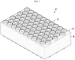
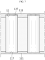
- FIG. 1 is a diagram illustrating a battery pack according to an embodiment of the present disclosure.
- the battery pack 50 includes a plurality of battery cells 52 and a pack case 56 for accommodating the plurality of battery cells, and the pack case 56 may include a potting resin R that covers all the sides of the plurality of battery cells 52, and is filled to a predetermined height between the plurality of battery cells 52.
- the plurality of battery cells 52 may include secondary batteries, for example, cylindrical secondary batteries, pouch type secondary batteries or prismatic secondary batteries.
- secondary batteries for example, cylindrical secondary batteries, pouch type secondary batteries or prismatic secondary batteries.
- the plurality of battery cells 52 may be positioned such that they are inserted into the potting resin R, with the upper and lower ends exposed at least in part.
- the plurality of battery cells 52 may have a structure of mounting a busbar member for electrical connection or connecting to any other component at the partially exposed upper and lower ends.
- the upper surface of the potting resin R may be disposed at a lower position by a predetermined height than the upper end of the plurality of battery cells 52 in the heightwise direction of the plurality of battery cells 52, and the lower surface of the potting resin R may be disposed at a higher position by a predetermined height than the lower end of the plurality of battery cells 52 in the heightwise direction of the plurality of battery cells 52.
- the potting resin R may include materials having high heat resistance, electrical insulating properties, weather resistance and water repellency.
- the potting resin R may include silicone resins.
- the pack case 56 since the pack case 56 includes the potting resin R filled between the battery cells 52 to fully cover the battery cells 52, it is possible to provide the battery pack 50 having a slimmer and simpler structure and a price competitiveness advantage in price compared to the conventional pack case structure including an assembly of a plurality of frame members.
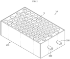
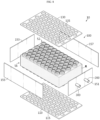
- FIG. 2 is a diagram illustrating an apparatus for manufacturing the battery pack of FIG. 1
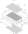
- FIG. 3 is an exploded perspective view of the apparatus for manufacturing a battery pack of FIG. 2 .
- the apparatus 10 for manufacturing a battery pack may manufacture the pack case 56 (see FIG. 1 ) for supporting and fixing the plurality of battery cells 52 (see FIG. 1 ) of the battery pack 50 (see FIG. 1 ).
- the apparatus 10 for manufacturing a battery pack may include a resin injection frame 100, a resin injection port 200 and an air outlet 300.
- the resin injection frame 100 may have an accommodation space S that accommodates the plurality of battery cells 52 to inject a resin R (see FIG. 1 ) for covering the plurality of battery cells 52.
- the resin injection frame 100 may be separated from the plurality of battery cells 52 and the cured resin R (see FIG. 1 ).
- the resin injection frame 100 may include a lower frame 110, an upper frame 130 a side frame 150.
- the lower frame 110 is used to cover the bottom of the plurality of battery cells 52, and may support the plurality of battery cells 52. To this end, the lower frame 110 may have a size that is large enough to cover the bottom of the plurality of battery cells 52.
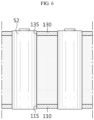
- the lower frame 110 may have a cell insertion hole 115.
- the cell insertion hole 115 is where the bottom of the plurality of battery cells 52 are inserted, and a plurality of cell insertion holes 115 may be provided. The number of cell insertion holes 115 corresponding to the number of battery cells 52 may be provided.
- the upper frame 130 may be disposed opposite the lower frame 110, and may cover the top of the plurality of battery cells 52. To this end, the upper frame 130 may have a size that is large enough to cover the top of the plurality of battery cells 52.
- the upper frame 130 may have a cell insertion hole 135.
- the cell insertion hole 135 is where the upper part of the plurality of battery cells 52 are inserted, and a plurality of cell insertion holes 135 may be provided. The number of cell insertion holes 135 corresponding to the number of battery cells 52 may be provided.
- the side frame 150 may be detachably connected to the lower frame 110 and the upper frame 130, and may be formed to cover the sides of the plurality of battery cells 52.
- the side frame 150 may include a first side plate 151, a second side plate 153, a third side plate 155 and a fourth side plate 157.
- the first side plate 151 may cover at least one side of the plurality of battery cells 52. Specifically, the first side plate 151 may cover the right side of the plurality of battery cells 52.
- the first side plate 151 may include the resin injection port 200 and the air outlet 300 as described below.
- the second side plate 153 may be disposed opposite the first side plate 151, and may cover at least one other side of the plurality of battery cells 52. Specifically, the second side plate 153 may cover the left side of the plurality of battery cells 52.
- the third side plate 155 may cover the front side of the plurality of battery cells 52.
- the third side plate 155 may be detachably coupled to the first side plate 151 and the second side plate 153
- the fourth side plate 157 may be disposed opposite the third side plate 155, and may cover the rear side of the plurality of battery cells 52.
- the fourth side plate 157 may be detachably coupled to the first side plate 151 and the second side plate 153
- the resin injection port 200 may be used to inject the resin R (see FIG. 5 ) into the accommodation space S.
- the resin R may be injected into the accommodation space S through the resin injection port 200 in a room temperature thin state.
- the resin R since the resin R is injected in room temperature state, it is possible to prevent thermal damage of the plurality of battery cells 52 caused by the injection of the resin R, compared to when the resin R is injected in heated state.
- the resin injection port 200 may be provided on one side of the resin injection frame 100. Specifically, the resin injection port 200 may be provided in the side frame 150. More specifically, the resin injection port 200 may be provided in the first side plate 151 of the side frame 150.
- the air outlet 300 is used to force air A (see FIG. 5 ) inside the accommodation space out when injecting the resin R (see FIG. 5 ), and may be spaced apart from the resin injection port 200.
- the resin R since air A inside the accommodation space S is forced out through the air outlet 300 when injecting the resin R, the resin R may be injected into the accommodation space S more uniformly and cured in the accommodation space S more uniformly.
- the air outlet 300 may be provided in the side frame 150. More specifically, the air outlet 300 may be provided in the first side plate 151 of the side frame 150.
- FIGS. 4 to 9 are diagrams illustrating a method for manufacturing a battery pack through the apparatus for manufacturing a battery pack of FIG. 2 .
- a manufacturer may place the plurality of battery cells 52 in the resin injection frame 100 when manufacturing the pack case of the battery pack. Specifically, the manufacturer may cover the plurality of battery cells 52 with the lower frame 110, the upper frame 130 and the side frame 150 of the resin injection frame 100 and couple the lower frame 110, the upper frame 130 and the side frame 150 one another. Accordingly, the accommodation space S (see FIG. 3 ) may be formed in the resin injection frame 100, and the plurality of battery cells 52 may be accommodated in the accommodation space S.
- the manufacturer may inject the resin R into the accommodation space S (see FIG. 2 ) in the resin injection frame 100 through the resin injection port 200.
- the resin R may be injected in a room temperature thin state to prevent thermal damage of the plurality of battery cells 52.
- air in the accommodation space S may be released from the resin injection frame 100 through the air outlet 300 to increase the injection efficiency of the resin R.
- the plurality of battery cells 52 when injecting the resin R (see FIG. 5 ), the plurality of battery cells 52 may be fixed when inserted into the cell insertion hole 115 of the lower frame 110 and the cell insertion hole 135 of the upper frame 130.
- the fixing structure of the plurality of battery cells 52 is not limited thereto, and the plurality of battery cells 52 may be fixed in any other manner.
- the plurality of battery cells 52 may be fixed when inserted into a cell insertion groove 117 provided with a groove structure of a predetermined depth in a lower frame 111 and a cell insertion groove 137 provided with a groove structure of a predetermined depth in an upper frame 131.
- the manufacturer may separate the resin injection frame 100 from the resin R and the plurality of battery cells 52. Specifically, the manufacturer may separate the lower frame 110, the upper frame 130 and the side frame 150 from the resin R and the plurality of battery cells 52 by disconnecting the connection of the lower frame 110, the upper frame 130 and the side frame 150 of the resin injection frame 100.
- the battery pack 50 may include the pack case 56 including the resin R through the manufacturing apparatus 10 (see FIG. 5 ).
- the pack case 56 including the potting resin may be a so-called cell-potting resin structure. In this embodiment, it is possible to ensure the insulating properties and mechanical strength through the pack case 56 including the resin R.
- the pack case 56 of the battery pack 50 in a more straightforward and efficient manner than the conventional pack case structure including a plurality of frame members, through the pack case 56 of the cell-potting resin structure.
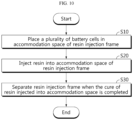
- FIG. 10 is a flowchart illustrating a method for manufacturing the battery pack of FIG. 1 .
- the manufacturer may place the plurality of battery cells in the accommodation space of the resin injection frame (S10).
- the manufacturer may inject a resin for covering the plurality of battery cells into the accommodation space of the resin injection frame (S20).
- the resin may be injected into the accommodation space through the resin injection port provided in the resin injection frame, and may be injected in room temperature state to prevent thermal damage of the plurality of battery cells.
- air in the accommodation space may be released from the resin injection frame through the air outlet.
- the resin injection frame may be separated from the plurality of battery cells and the cured resin (S30).
- the cured resin may act as a pack case to accommodate and cover the plurality of battery cells.
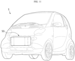
- FIG. 11 is a diagram illustrating a vehicle including the battery pack according to an embodiment of the present disclosure.
- the battery pack 50 may be provided in the vehicle 1 as a fuel source of the vehicle.
- the battery pack 50 may be provided in the vehicle 1 such as an electric vehicle, a hybrid electric vehicle and any other application using the battery pack 50 as a fuel source.
- the battery pack 50 may be provided in any other device, apparatus and equipment using secondary batteries, for example, an energy storage system.
- the battery pack 50 of this embodiment may be mounted in the vehicle 1 in a modularized form.
- a plurality of battery packs 50 may be provided according to the required capacity and may be mounted in the vehicle 1 such that they are electrically connected to each other in the vehicle 1.
- the pack case of the battery pack 50 is integrally formed using the potting resin as opposed to the conventional art including a plurality of plate members, it is possible to achieve the slim design of the battery pack 50 and significantly increase the energy density. Additionally, in this embodiment, it is possible to modularize the plurality of battery packs 50 in a more straightforward and convenient manner through the slim structure of the battery pack 50.
- the battery pack 50 with price competitiveness and reduced manufacturing cost, and the apparatus 10 and method for manufacturing a battery pack.
Landscapes
- Chemical Kinetics & Catalysis (AREA)
- Electrochemistry (AREA)
- General Chemical & Material Sciences (AREA)
- Chemical & Material Sciences (AREA)
- Engineering & Computer Science (AREA)
- Manufacturing & Machinery (AREA)
- Mechanical Engineering (AREA)
- Aviation & Aerospace Engineering (AREA)
- Physics & Mathematics (AREA)
- Thermal Sciences (AREA)
- Oral & Maxillofacial Surgery (AREA)
- Health & Medical Sciences (AREA)
- Battery Mounting, Suspending (AREA)
Applications Claiming Priority (2)
| Application Number | Priority Date | Filing Date | Title |
|---|---|---|---|
| KR1020210003549A KR20220101474A (ko) | 2021-01-11 | 2021-01-11 | 배터리 팩, 이러한 배터리 팩의 제조 장치 및 제조 방법 |
| PCT/KR2022/000503 WO2022149966A1 (fr) | 2021-01-11 | 2022-01-11 | Bloc-batterie, et dispositif de fabrication et procédé de fabrication pour bloc-batterie |
Publications (2)
| Publication Number | Publication Date |
|---|---|
| EP4184680A1 true EP4184680A1 (fr) | 2023-05-24 |
| EP4184680A4 EP4184680A4 (fr) | 2024-10-02 |
Family
ID=82357327
Family Applications (1)
| Application Number | Title | Priority Date | Filing Date |
|---|---|---|---|
| EP22736943.6A Pending EP4184680A4 (fr) | 2021-01-11 | 2022-01-11 | Bloc-batterie, et dispositif de fabrication et procédé de fabrication pour bloc-batterie |
Country Status (5)
| Country | Link |
|---|---|
| US (1) | US20230187755A1 (fr) |
| EP (1) | EP4184680A4 (fr) |
| KR (1) | KR20220101474A (fr) |
| CN (1) | CN115668608A (fr) |
| WO (1) | WO2022149966A1 (fr) |
Families Citing this family (1)
| Publication number | Priority date | Publication date | Assignee | Title |
|---|---|---|---|---|
| EP4425693A1 (fr) * | 2022-12-22 | 2024-09-04 | LG Energy Solution, Ltd. | Module de batterie et bloc-batterie, et véhicule les comprenant |
Family Cites Families (10)
| Publication number | Priority date | Publication date | Assignee | Title |
|---|---|---|---|---|
| JP4176884B2 (ja) * | 1998-10-08 | 2008-11-05 | ポリマテック株式会社 | 電気自動車のバッテリ格納構造および格納方法 |
| FR2924857B1 (fr) * | 2007-12-06 | 2014-06-06 | Valeo Equip Electr Moteur | Dispositif d'alimentation electrique comportant un bac de reception d'unites de stockage a ultra capacite |
| KR101084801B1 (ko) * | 2009-02-18 | 2011-11-21 | 삼성에스디아이 주식회사 | 이차 전지의 제조 방법 및 이에 의해 제조된 이차 전지 |
| WO2012164923A1 (fr) * | 2011-05-30 | 2012-12-06 | パナソニック株式会社 | Bloc-batterie et son procédé de fabrication |
| DE102015219280A1 (de) * | 2015-10-06 | 2017-04-06 | Robert Bosch Gmbh | Batteriesystem mit Vergussmasse |
| JP6798432B2 (ja) * | 2017-06-20 | 2020-12-09 | トヨタ自動車株式会社 | 組電池、電池モジュール及び組電池の製造方法 |
| KR102258178B1 (ko) * | 2017-10-27 | 2021-06-03 | 주식회사 엘지에너지솔루션 | 냉각 및 조립 구조를 단순화시킨 배터리 모듈 및 그 제조방법 |
| JP7093007B2 (ja) * | 2018-08-01 | 2022-06-29 | アイコム株式会社 | 筐体への樹脂充填方法及びそれに用いられる治具 |
| KR102378527B1 (ko) * | 2018-12-05 | 2022-03-23 | 주식회사 엘지에너지솔루션 | 전지 모듈 및 그 제조 방법 |
| KR102208161B1 (ko) | 2019-07-02 | 2021-01-27 | 홍진영어조합법인 | 친환경 황동어망을 갖는 가두리 양식시설 |
-
2021
- 2021-01-11 KR KR1020210003549A patent/KR20220101474A/ko active Search and Examination
-
2022
- 2022-01-11 EP EP22736943.6A patent/EP4184680A4/fr active Pending
- 2022-01-11 WO PCT/KR2022/000503 patent/WO2022149966A1/fr unknown
- 2022-01-11 US US17/921,041 patent/US20230187755A1/en active Pending
- 2022-01-11 CN CN202280004439.4A patent/CN115668608A/zh active Pending
Also Published As
| Publication number | Publication date |
|---|---|
| EP4184680A4 (fr) | 2024-10-02 |
| US20230187755A1 (en) | 2023-06-15 |
| KR20220101474A (ko) | 2022-07-19 |
| CN115668608A (zh) | 2023-01-31 |
| WO2022149966A1 (fr) | 2022-07-14 |
Similar Documents
| Publication | Publication Date | Title |
|---|---|---|
| CN111066173B (zh) | 电池模块、包括电池模块的电池组和包括电池组的车辆 | |
| CN107615564B (zh) | 电池模块、包括电池模块的电池组和包括电池组的车辆 | |
| CN108780934B (zh) | 电池模块、包括电池模块的电池组以及包括电池组的车辆 | |
| EP3291360B1 (fr) | Bloc-batterie et véhicule incluant un tel bloc-batterie | |
| EP3696905B1 (fr) | Module de batterie et bloc-batterie comprenant ledit module de batterie | |
| EP3361555A1 (fr) | Bloc-batterie et véhicule comprenant un bloc-batterie | |
| US20240195017A1 (en) | Battery Module, Battery Pack Including Same Battery Module, and Automobile Including Same Battery Pack | |
| EP3460871A1 (fr) | Module de batterie, bloc-batterie comprenant le module de batterie, et véhicule automobile comprenant un bloc-batterie | |
| KR102352686B1 (ko) | 배터리 모듈, 이러한 배터리 모듈을 포함하는 배터리 팩 및 이러한 배터리 팩을 포함하는 자동차 | |
| EP4019179B1 (fr) | Module de batterie, et bloc-batterie et véhicule comprenant le module de batterie | |
| EP3522254B1 (fr) | Module de batterie, bloc-batterie comprenant un module de batterie, et véhicule comprenant un bloc-batterie | |
| US20240274956A1 (en) | Battery pack and vehicle including same | |
| EP4184680A1 (fr) | Bloc-batterie, et dispositif de fabrication et procédé de fabrication pour bloc-batterie | |
| CN116018714A (zh) | 电池模块及包括该电池模块的电池组 | |
| KR102455471B1 (ko) | 배터리 셀, 이를 포함하는 배터리 모듈, 배터리 랙 및 전력 저장 장치 | |
| CN113678308A (zh) | 电池模块和包括该电池模块的电池组 | |
| EP4203159A2 (fr) | Module de batterie, bloc-batterie le comprenant, et véhicule | |
| KR20220125786A (ko) | 배터리 팩 및 이를 포함하는 자동차 | |
| CN114173898A (zh) | 电池组和包括该电池组的装置 | |
| KR101514426B1 (ko) | 커넥터, 이를 포함하는 배터리 팩 및 배터리 팩의 조립 방법 | |
| KR102165018B1 (ko) | 배터리 모듈, 이러한 배터리 모듈을 포함하는 배터리 팩 및 이러한 배터리 팩을 포함하는 자동차 | |
| KR20210016826A (ko) | 냉각 부재를 구비한 배터리 모듈 및 배터리 팩 및 자동차 |
Legal Events
| Date | Code | Title | Description |
|---|---|---|---|
| STAA | Information on the status of an ep patent application or granted ep patent |
Free format text: STATUS: THE INTERNATIONAL PUBLICATION HAS BEEN MADE |
|
| PUAI | Public reference made under article 153(3) epc to a published international application that has entered the european phase |
Free format text: ORIGINAL CODE: 0009012 |
|
| STAA | Information on the status of an ep patent application or granted ep patent |
Free format text: STATUS: REQUEST FOR EXAMINATION WAS MADE |
|
| 17P | Request for examination filed |
Effective date: 20230216 |
|
| AK | Designated contracting states |
Kind code of ref document: A1 Designated state(s): AL AT BE BG CH CY CZ DE DK EE ES FI FR GB GR HR HU IE IS IT LI LT LU LV MC MK MT NL NO PL PT RO RS SE SI SK SM TR |
|
| DAV | Request for validation of the european patent (deleted) | ||
| DAX | Request for extension of the european patent (deleted) | ||
| RIC1 | Information provided on ipc code assigned before grant |
Ipc: B29L 31/34 20060101ALN20240621BHEP Ipc: B29C 45/14 20060101ALI20240621BHEP Ipc: H01M 10/613 20140101ALI20240621BHEP Ipc: B29K 83/00 20060101ALI20240621BHEP Ipc: B29C 33/10 20060101ALI20240621BHEP Ipc: B29C 35/02 20060101ALI20240621BHEP Ipc: B29C 39/26 20060101ALI20240621BHEP Ipc: H01M 10/653 20140101ALI20240621BHEP Ipc: H01M 50/293 20210101ALI20240621BHEP Ipc: B29C 39/10 20060101ALI20240621BHEP Ipc: H01M 50/204 20210101ALI20240621BHEP Ipc: H01M 50/249 20210101ALI20240621BHEP Ipc: H01M 50/213 20210101ALI20240621BHEP Ipc: H01M 50/24 20210101AFI20240621BHEP |
|
| A4 | Supplementary search report drawn up and despatched |
Effective date: 20240903 |
|
| RIC1 | Information provided on ipc code assigned before grant |
Ipc: B29L 31/34 20060101ALN20240828BHEP Ipc: B29C 45/14 20060101ALI20240828BHEP Ipc: H01M 10/613 20140101ALI20240828BHEP Ipc: B29K 83/00 20060101ALI20240828BHEP Ipc: B29C 33/10 20060101ALI20240828BHEP Ipc: B29C 35/02 20060101ALI20240828BHEP Ipc: B29C 39/26 20060101ALI20240828BHEP Ipc: H01M 10/653 20140101ALI20240828BHEP Ipc: H01M 50/293 20210101ALI20240828BHEP Ipc: B29C 39/10 20060101ALI20240828BHEP Ipc: H01M 50/204 20210101ALI20240828BHEP Ipc: H01M 50/249 20210101ALI20240828BHEP Ipc: H01M 50/213 20210101ALI20240828BHEP Ipc: H01M 50/24 20210101AFI20240828BHEP |