EP4184663A1 - Batteriemodul und elektrische vorrichtung - Google Patents
Batteriemodul und elektrische vorrichtung Download PDFInfo
- Publication number
- EP4184663A1 EP4184663A1 EP22208754.6A EP22208754A EP4184663A1 EP 4184663 A1 EP4184663 A1 EP 4184663A1 EP 22208754 A EP22208754 A EP 22208754A EP 4184663 A1 EP4184663 A1 EP 4184663A1
- Authority
- EP
- European Patent Office
- Prior art keywords
- connecting member
- hole
- side wall
- protrusion
- battery module
- Prior art date
- Legal status (The legal status is an assumption and is not a legal conclusion. Google has not performed a legal analysis and makes no representation as to the accuracy of the status listed.)
- Granted
Links
Images


Classifications
-
- H—ELECTRICITY
- H01—ELECTRIC ELEMENTS
- H01M—PROCESSES OR MEANS, e.g. BATTERIES, FOR THE DIRECT CONVERSION OF CHEMICAL ENERGY INTO ELECTRICAL ENERGY
- H01M10/00—Secondary cells; Manufacture thereof
- H01M10/60—Heating or cooling; Temperature control
- H01M10/61—Types of temperature control
- H01M10/613—Cooling or keeping cold
-
- H—ELECTRICITY
- H01—ELECTRIC ELEMENTS
- H01M—PROCESSES OR MEANS, e.g. BATTERIES, FOR THE DIRECT CONVERSION OF CHEMICAL ENERGY INTO ELECTRICAL ENERGY
- H01M50/00—Constructional details or processes of manufacture of the non-active parts of electrochemical cells other than fuel cells, e.g. hybrid cells
- H01M50/10—Primary casings; Jackets or wrappings
- H01M50/172—Arrangements of electric connectors penetrating the casing
- H01M50/174—Arrangements of electric connectors penetrating the casing adapted for the shape of the cells
- H01M50/178—Arrangements of electric connectors penetrating the casing adapted for the shape of the cells for pouch or flexible bag cells
-
- H—ELECTRICITY
- H01—ELECTRIC ELEMENTS
- H01M—PROCESSES OR MEANS, e.g. BATTERIES, FOR THE DIRECT CONVERSION OF CHEMICAL ENERGY INTO ELECTRICAL ENERGY
- H01M10/00—Secondary cells; Manufacture thereof
- H01M10/60—Heating or cooling; Temperature control
- H01M10/64—Heating or cooling; Temperature control characterised by the shape of the cells
- H01M10/647—Prismatic or flat cells, e.g. pouch cells
-
- H—ELECTRICITY
- H01—ELECTRIC ELEMENTS
- H01M—PROCESSES OR MEANS, e.g. BATTERIES, FOR THE DIRECT CONVERSION OF CHEMICAL ENERGY INTO ELECTRICAL ENERGY
- H01M10/00—Secondary cells; Manufacture thereof
- H01M10/60—Heating or cooling; Temperature control
- H01M10/65—Means for temperature control structurally associated with the cells
- H01M10/653—Means for temperature control structurally associated with the cells characterised by electrically insulating or thermally conductive materials
-
- H—ELECTRICITY
- H01—ELECTRIC ELEMENTS
- H01M—PROCESSES OR MEANS, e.g. BATTERIES, FOR THE DIRECT CONVERSION OF CHEMICAL ENERGY INTO ELECTRICAL ENERGY
- H01M10/00—Secondary cells; Manufacture thereof
- H01M10/60—Heating or cooling; Temperature control
- H01M10/65—Means for temperature control structurally associated with the cells
- H01M10/655—Solid structures for heat exchange or heat conduction
- H01M10/6553—Terminals or leads
-
- H—ELECTRICITY
- H01—ELECTRIC ELEMENTS
- H01M—PROCESSES OR MEANS, e.g. BATTERIES, FOR THE DIRECT CONVERSION OF CHEMICAL ENERGY INTO ELECTRICAL ENERGY
- H01M50/00—Constructional details or processes of manufacture of the non-active parts of electrochemical cells other than fuel cells, e.g. hybrid cells
- H01M50/10—Primary casings; Jackets or wrappings
- H01M50/102—Primary casings; Jackets or wrappings characterised by their shape or physical structure
- H01M50/105—Pouches or flexible bags
-
- H—ELECTRICITY
- H01—ELECTRIC ELEMENTS
- H01M—PROCESSES OR MEANS, e.g. BATTERIES, FOR THE DIRECT CONVERSION OF CHEMICAL ENERGY INTO ELECTRICAL ENERGY
- H01M50/00—Constructional details or processes of manufacture of the non-active parts of electrochemical cells other than fuel cells, e.g. hybrid cells
- H01M50/20—Mountings; Secondary casings or frames; Racks, modules or packs; Suspension devices; Shock absorbers; Transport or carrying devices; Holders
- H01M50/204—Racks, modules or packs for multiple batteries or multiple cells
- H01M50/207—Racks, modules or packs for multiple batteries or multiple cells characterised by their shape
- H01M50/211—Racks, modules or packs for multiple batteries or multiple cells characterised by their shape adapted for pouch cells
-
- H—ELECTRICITY
- H01—ELECTRIC ELEMENTS
- H01M—PROCESSES OR MEANS, e.g. BATTERIES, FOR THE DIRECT CONVERSION OF CHEMICAL ENERGY INTO ELECTRICAL ENERGY
- H01M50/00—Constructional details or processes of manufacture of the non-active parts of electrochemical cells other than fuel cells, e.g. hybrid cells
- H01M50/20—Mountings; Secondary casings or frames; Racks, modules or packs; Suspension devices; Shock absorbers; Transport or carrying devices; Holders
- H01M50/218—Mountings; Secondary casings or frames; Racks, modules or packs; Suspension devices; Shock absorbers; Transport or carrying devices; Holders characterised by the material
- H01M50/22—Mountings; Secondary casings or frames; Racks, modules or packs; Suspension devices; Shock absorbers; Transport or carrying devices; Holders characterised by the material of the casings or racks
- H01M50/222—Inorganic material
-
- H—ELECTRICITY
- H01—ELECTRIC ELEMENTS
- H01M—PROCESSES OR MEANS, e.g. BATTERIES, FOR THE DIRECT CONVERSION OF CHEMICAL ENERGY INTO ELECTRICAL ENERGY
- H01M50/00—Constructional details or processes of manufacture of the non-active parts of electrochemical cells other than fuel cells, e.g. hybrid cells
- H01M50/20—Mountings; Secondary casings or frames; Racks, modules or packs; Suspension devices; Shock absorbers; Transport or carrying devices; Holders
- H01M50/262—Mountings; Secondary casings or frames; Racks, modules or packs; Suspension devices; Shock absorbers; Transport or carrying devices; Holders with fastening means, e.g. locks
- H01M50/264—Mountings; Secondary casings or frames; Racks, modules or packs; Suspension devices; Shock absorbers; Transport or carrying devices; Holders with fastening means, e.g. locks for cells or batteries, e.g. straps, tie rods or peripheral frames
-
- H—ELECTRICITY
- H01—ELECTRIC ELEMENTS
- H01M—PROCESSES OR MEANS, e.g. BATTERIES, FOR THE DIRECT CONVERSION OF CHEMICAL ENERGY INTO ELECTRICAL ENERGY
- H01M50/00—Constructional details or processes of manufacture of the non-active parts of electrochemical cells other than fuel cells, e.g. hybrid cells
- H01M50/20—Mountings; Secondary casings or frames; Racks, modules or packs; Suspension devices; Shock absorbers; Transport or carrying devices; Holders
- H01M50/284—Mountings; Secondary casings or frames; Racks, modules or packs; Suspension devices; Shock absorbers; Transport or carrying devices; Holders with incorporated circuit boards, e.g. printed circuit boards [PCB]
- H01M50/287—Fixing of circuit boards to lids or covers
-
- H—ELECTRICITY
- H01—ELECTRIC ELEMENTS
- H01M—PROCESSES OR MEANS, e.g. BATTERIES, FOR THE DIRECT CONVERSION OF CHEMICAL ENERGY INTO ELECTRICAL ENERGY
- H01M50/00—Constructional details or processes of manufacture of the non-active parts of electrochemical cells other than fuel cells, e.g. hybrid cells
- H01M50/20—Mountings; Secondary casings or frames; Racks, modules or packs; Suspension devices; Shock absorbers; Transport or carrying devices; Holders
- H01M50/289—Mountings; Secondary casings or frames; Racks, modules or packs; Suspension devices; Shock absorbers; Transport or carrying devices; Holders characterised by spacing elements or positioning means within frames, racks or packs
-
- H—ELECTRICITY
- H01—ELECTRIC ELEMENTS
- H01M—PROCESSES OR MEANS, e.g. BATTERIES, FOR THE DIRECT CONVERSION OF CHEMICAL ENERGY INTO ELECTRICAL ENERGY
- H01M50/00—Constructional details or processes of manufacture of the non-active parts of electrochemical cells other than fuel cells, e.g. hybrid cells
- H01M50/50—Current conducting connections for cells or batteries
- H01M50/502—Interconnectors for connecting terminals of adjacent batteries; Interconnectors for connecting cells outside a battery casing
- H01M50/519—Interconnectors for connecting terminals of adjacent batteries; Interconnectors for connecting cells outside a battery casing comprising printed circuit boards [PCB]
-
- H—ELECTRICITY
- H01—ELECTRIC ELEMENTS
- H01M—PROCESSES OR MEANS, e.g. BATTERIES, FOR THE DIRECT CONVERSION OF CHEMICAL ENERGY INTO ELECTRICAL ENERGY
- H01M50/00—Constructional details or processes of manufacture of the non-active parts of electrochemical cells other than fuel cells, e.g. hybrid cells
- H01M50/50—Current conducting connections for cells or batteries
- H01M50/543—Terminals
- H01M50/547—Terminals characterised by the disposition of the terminals on the cells
- H01M50/55—Terminals characterised by the disposition of the terminals on the cells on the same side of the cell
-
- H—ELECTRICITY
- H01—ELECTRIC ELEMENTS
- H01M—PROCESSES OR MEANS, e.g. BATTERIES, FOR THE DIRECT CONVERSION OF CHEMICAL ENERGY INTO ELECTRICAL ENERGY
- H01M50/00—Constructional details or processes of manufacture of the non-active parts of electrochemical cells other than fuel cells, e.g. hybrid cells
- H01M50/50—Current conducting connections for cells or batteries
- H01M50/543—Terminals
- H01M50/552—Terminals characterised by their shape
- H01M50/553—Terminals adapted for prismatic, pouch or rectangular cells
- H01M50/557—Plate-shaped terminals
-
- H—ELECTRICITY
- H01—ELECTRIC ELEMENTS
- H01M—PROCESSES OR MEANS, e.g. BATTERIES, FOR THE DIRECT CONVERSION OF CHEMICAL ENERGY INTO ELECTRICAL ENERGY
- H01M50/00—Constructional details or processes of manufacture of the non-active parts of electrochemical cells other than fuel cells, e.g. hybrid cells
- H01M50/50—Current conducting connections for cells or batteries
- H01M50/572—Means for preventing undesired use or discharge
- H01M50/584—Means for preventing undesired use or discharge for preventing incorrect connections inside or outside the batteries
-
- Y—GENERAL TAGGING OF NEW TECHNOLOGICAL DEVELOPMENTS; GENERAL TAGGING OF CROSS-SECTIONAL TECHNOLOGIES SPANNING OVER SEVERAL SECTIONS OF THE IPC; TECHNICAL SUBJECTS COVERED BY FORMER USPC CROSS-REFERENCE ART COLLECTIONS [XRACs] AND DIGESTS
- Y02—TECHNOLOGIES OR APPLICATIONS FOR MITIGATION OR ADAPTATION AGAINST CLIMATE CHANGE
- Y02E—REDUCTION OF GREENHOUSE GAS [GHG] EMISSIONS, RELATED TO ENERGY GENERATION, TRANSMISSION OR DISTRIBUTION
- Y02E60/00—Enabling technologies; Technologies with a potential or indirect contribution to GHG emissions mitigation
- Y02E60/10—Energy storage using batteries
Definitions
- This application relates to the field of energy storage technologies, and in particular, to a battery module and an electric device.
- a current conventional heat dissipation method is to add a heat dissipation member between cells, but with such heat dissipation method, limited heat is dissipated for the circuit board.
- An embodiment of this application provides a battery module, including a housing assembly, a cell assembly, a circuit board, and a first connecting member.
- the housing assembly includes a first side wall and a second side wall.
- the first side wall is provided with a first through hole.
- the second side wall is provided with a second through hole.
- the cell assembly is accommodated in the housing assembly.
- Each cell assembly includes cells.
- the cell includes a cell housing, an electrode assembly disposed in the cell housing, and an electrode terminal connecting to the electrode assembly and led out of the cell housing.
- the circuit board connects to the electrode terminal.
- the first connecting member connects to the circuit board.
- the first connecting member is disposed in the first through hole and the second through hole.
- the first connecting member is provided with a first channel. The first channel communicates with the first through hole and the second through hole.
- the first connecting member dissipates heat of the circuit board out of the first through hole and the second through hole to an external environment via the first channel, improving heat dissipation for the circuit board, thereby lowering temperature of the battery module.
- the first side wall and the second side wall are disposed opposite each other in a first direction.
- the first side wall is provided with a first protrusion facing towards the second side wall.
- the first protrusion is at least partially disposed in the first channel.
- the first side wall is provided with a first protrusion facing towards the second side wall, and the first protrusion connects to an edge of the first through hole.
- the first protrusion is provided with a first hole.
- the first hole communicates with the first through hole.
- the first protrusion is at least partially disposed in the first channel, or the first connecting member is partially located in the first hole.
- the first connecting member is partially located in the first hole.
- An adhesive is provided between the first protrusion and the first connecting member.
- a gap between the first protrusion and the first connecting member is sealed through the adhesive, so that water entering the housing assembly can be reduced, thereby reducing a risk of short circuit caused by the water entering the battery module.
- the second side wall is provided with a second protrusion facing towards the first side wall, and the second protrusion is at least partially disposed in the first channel.
- the second side wall is provided with a second protrusion facing towards the first side wall.
- the second protrusion connects to an edge of the second through hole.
- the second protrusion is provided with a second hole.
- the second hole communicates with the second through hole.
- the second protrusion is at least partially disposed in the first channel, or the first connecting member is partially located in the second hole.
- the first connecting member is partially located in the second hole.
- An adhesive is provided between the second protrusion and the first connecting member.
- a gap between the second protrusion and the first connecting member is sealed through the adhesive, so that water entering the housing assembly can be reduced, thereby reducing a risk of short circuit caused by the water entering the battery module.
- the first protrusion is disposed in the first channel.
- the first connecting member is connected to the first side wall.
- the first connecting member is in contact connection with the first side wall.
- the first connecting member is connected to the first side wall through glue and the like.
- a projection of the first through hole is larger than and covers a projection of the second through hole.
- a diameter of the first through hole being larger than a diameter of the second through hole enhances convection of air, further improving heat dissipation.
- a thermally conductive member is further included.
- the thermally conductive member is disposed between the first connecting member and the electrode terminal.
- the circuit board in a second direction perpendicular to the first direction, is provided with a plurality of third through holes.
- One electrode terminal passes through the third through hole to connect to the circuit board.
- a projection of the first connecting member is located between projections of adjacent third through holes.
- the third direction is perpendicular to the first direction and the second direction, implementing better heat dissipation for electrode terminals located on two sides of the first connecting member.
- the projection of the first connecting member and the projection of the third through hole are away from each other, reducing intervention of the first connecting member and the electrode terminal.
- a second connecting member is further included.
- the second connecting member includes a first component disposed between adjacent cells.
- the first component connects to the first connecting member.
- the first side wall and the second side wall are disposed opposite each other in the first direction, and in the second direction perpendicular to the first direction, a projection of the first component and a projection of the cell housing at least partially overlap.
- the first component being disposed between the adjacent cells increases a contact area between the first component and the cell housing, thereby improving heat dissipation for the adjacent cells.
- the second connecting member further includes a second component connecting to the first component.
- the second component extends from between adjacent cells.
- the second component is bent toward the adjacent cells and is in contact connection with the cell.
- a projection of the second component and a projection of the adjacent cells at least partially overlap. Provision of the second component increases a contact area between the second connecting member and the cell housing, thereby further improving heat dissipation for the cell.
- the second component is in contact connection with the housing assembly. Heat is transferred to the housing assembly and is dissipated through the housing assembly, thereby further improving heat dissipation for the battery module.
- first connecting member and the second connecting member are integrally formed through bending to enhance structural strength of the first connecting member and the second connecting member.
- surfaces of the first connecting member and the second connecting member are provided with an insulation layer.
- the cell housing includes a first portion and a second portion.
- the electrode assembly is disposed on the first portion.
- the second portion connects to the first portion.
- the electrode terminal extends from the second portion.
- the first portion and the second portion fit to form a third depression.
- the first connecting member is at least partially disposed in the third depression.
- a first structural member is further included.
- the first structural member is provided with a fourth depression.
- the circuit board is disposed in the fourth depression.
- the first structural member is provided with a first opening and a second opening.
- the first connecting member is disposed at the first opening and the second opening.
- the first connecting member is at least partially located in the second depression.
- An embodiment of this application further provides an electric device, including the battery module according to any one of the foregoing embodiments.
- the first connecting member dissipates heat of the circuit board and the cell assembly out of the first through hole and the second through hole to an external environment via the first channel, improving heat dissipation for the circuit board, thereby lowering temperature of the battery module.
- battery module 100 housing assembly 10 first through hole 10a second through hole 10b first side wall 11 first protrusion 111 first hole 1110 second side wall 12 second protrusion 121 second hole 1210 first housing 13 second housing 14 cell assembly 20 cell 21 first side face 21a second side face 21b third side face 21c cell housing 211 first portion 211a second portion 211b third depression 211c electrode terminal 212 welding portion 212a first terminal 212b second terminal 212c circuit board 30 third through hole 31 first connecting member 40 first channel 40a first structural member 50 top plate 50a side plate 50b fourth depression 51 first opening 52 second opening 53 second connecting member 60 first component 61 fourth adhesive 61a first connecting portion 611 second connecting portion 612 second component 62 third connecting portion 621 fourth connecting portion 622 electric device 200 first direction X second direction Y third direction Z
- a component When a component is deemed as being “provided on” another component, it may be directly provided on the another component, or there may be a component in between. When a component is deemed as being “connected to” another component, it may be directly connected to the another component, or there may be a component in between.
- a specified included angle may be present between the two components, and the included angle between the two components have an allowable tolerance of 0- ⁇ 5%.
- a tolerance range between the two components is greater than 0° and is less than or equal to 4.5°.
- projections of two components are the same or overlap, the two components have an allowable tolerance of 0- ⁇ 10%.
- one component has the same projection as the other component in shape, and projection areas have a tolerance of 0- ⁇ 10%.
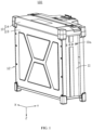
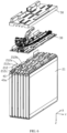
- an embodiment of this application provides a battery module 100, including a housing assembly 10, a cell assembly 20, a circuit board 30, and a first connecting member 40.
- the housing assembly 10 is provided with a first through hole 10a and a second through hole 10b, where the first through hole 10a and the second through hole 10b communicate with the outside.
- the cell assembly 20 is disposed in the housing assembly 10.
- the circuit board 30 is disposed in the housing assembly 10 and connects to the cell assembly 20.
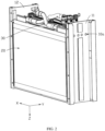
- the first connecting member 40 is located below the circuit board 30, the first connecting member 40 is provided with a first channel 40a, and the first channel 40a communicates with the first through hole 10a and the second through hole 10b.
- the first connecting member 40 dissipates heat of the circuit board 30 and the cell assembly 20 out of the first through hole 10a and the second through hole 10b to an external environment via the first channel 40a, improving heat dissipation for the circuit board 30, thereby lowering temperature of the battery module 100.
- the first connecting member 40 is in contact connection with the circuit board 30. In another embodiment, a gap is provided between the first connecting member 40 and the circuit board 30. In another embodiment, the first connecting member 40 and the circuit board 30 are connected via the thermally conductive member.
- the thermally conductive member includes at least one of a thermally conductive adhesive or a thermally conductive sheet.
- the battery module 100 may use outside air to take away heat of the circuit board 30 and the cell assembly 20 through flow of air.
- the battery module 100 may be applied to a device that is in a static state during use, and when the battery module 100 is in a static state, heat dissipation can be implemented through natural air flow or an external air cooling device.
- the battery module 100 may be applied to a device that is in a dynamic state during use, for example, a drone or an electric motor bicycle. Because air flow velocity is quicker during moving of the device, quick heat dissipation for the battery module 100 can be implemented.
- the housing assembly 10 includes a first side wall 11 and a second side wall 12, the first through hole 10a is provided on the first side wall 11, and the second through hole 10b is provided on the second side wall 12.
- the first side wall 11 and the second side wall 12 are disposed opposite each other in a first direction X.
- the first through hole 10a passes through the first side wall 11, and the second through hole 10b passes through the second side wall 12.
- the first through hole 10a and the second through hole 10b are both provided in plurality and are the same in quantity, and in the first direction X, a projection of the first through hole 10a and a projection of the second through hole 10b overlap.
- the first through hole 10a is an air inlet
- the second through hole 10b is an air outlet. Air enters through the first through hole 10a, flows through the first channel 40a, and flows out of the second through hole 10b, improving heat dissipation. It can be understood that when the battery module 100 moves in a direction opposite to the first direction X or an air flow direction of the external air cooling device is in a direction opposite to the first direction X, the first through hole 10a is an air outlet, and the second through hole 10b is an air inlet.
- a projection of the first through hole 10a is larger than and covers a projection of the second through hole 10b.
- the first through hole 10a is an air inlet
- the second through hole 10b is an air outlet, with a diameter of the first through hole 10a being larger than a diameter of the second through hole 10b, so as to enhance convection of air, further improving heat dissipation.
- first through hole 10a and the second through hole 10b are different in quantity.
- One first through hole 10a corresponds to a plurality of second through holes 10b, or one second through hole 10b corresponds to a plurality of first through holes 10a.
- one first through hole 10a corresponds to two second through holes 10b, one end of the first connecting member 40 is disposed in the first through hole 10a, and another end thereof is provided with two branches, where the two branches are both provided with the first channel 40a, and the two branches are correspondingly disposed in the two second through holes 10b.
- the housing assembly 10 includes a first housing 13 and a second housing 14.
- the first housing 13 includes a first side wall 11 and a second side wall 12.
- the first housing 13 has a first space, and the cell assembly 20 is disposed in the first space.
- the second housing 14 connects to the first housing 13 to enclose the first space.
- the second housing 14 has a second space, and the cell assembly 20 is at least partially disposed in the second space.
- the first housing 13 and the second housing 14 are connected through a snap-fitted manner such as a fastener fitting a fastening hole.
- the first housing 13 and the second housing 14 may alternatively be fixedly connected through a fastener such as a screw or a bonding manner such as bonding through adhesive.
- the first side wall 11 is provided with a first protrusion 111, the first protrusion 111 is disposed facing towards the second side wall 12, and the first protrusion 111 is at least partially disposed in the first channel 40a.
- the first protrusion 111 is disposed in the first direction X.
- the first protrusion 111 is disposed surrounding part of a periphery of the first through hole 10a, and the first protrusion 111 is at least partially disposed in the first channel 40a.
- the first protrusion 111 is connected to the first connecting member 40 through a first adhesive (not shown in the figure) to fasten the first connecting member 40.
- the first protrusion 111 is disposed in the first channel 40a, and the first connecting member 40 is connected to the first side wall 11.
- the first connecting member 40 is in contact connection with the first side wall 11.
- the first connecting member 40 is connected to the first side wall 11 through glue and the like.
- the first protrusion 111 is disposed surrounding the periphery of the first through hole 10a. Further, the first protrusion 111 is connected to an edge of the first through hole 10a in a surrounding manner. The first protrusion 111 is at least partially disposed in the first channel 40a. The first protrusion 111 connects to the first connecting member 40 and is disposed in the first channel 40a. The first protrusion 111 is provided with a first hole 1110, where the first hole 1110 communicates with the first through hole 10a.
- a first adhesive is provided between the first protrusion 111 and the first connecting member 40, and a gap between the first protrusion 111 and the first connecting member 40 is sealed through the first adhesive, so that water entering the housing assembly 10 can be reduced, thereby reducing a risk of short circuit caused by the water entering the battery module 100.
- the first adhesive includes a sealant.
- the first protrusion 111 is disposed in the first channel 40a, and the first connecting member 40 is connected to the first side wall 11.
- the first connecting member 40 is in contact connection with the first side wall 11.
- the first connecting member 40 is connected to the first side wall 11 through glue and the like.
- the first connecting member 40 is partially located in the first hole 1110.
- An adhesive is provided between the first protrusion 111 and the first connecting member 40, and a gap between the first protrusion 111 and the first connecting member 40 is sealed through the adhesive, so that water entering the housing assembly 10 can be reduced, thereby reducing a risk of short circuit caused by the water entering the battery module 100.
- the adhesive includes a sealant.
- a surface of the first side wall 11 facing towards the second side wall 12 is provided with a first depression (not shown in the figure), and one end of the first connecting member 40 is disposed in the first depression.
- the first depression is disposed surrounding the periphery of the first through hole 10a.
- a first adhesive is provided between the first depression and the first connecting member 40. A gap between the first depression and the first connecting member 40 is sealed through the first adhesive, so that water entering the housing assembly 10 can be reduced, thereby reducing a risk of short circuit caused by the water entering the battery module 100.
- the second side wall 12 is provided with a second protrusion 121, the second protrusion 121 is disposed facing towards the first side wall 11, and the second protrusion 121 is at least partially disposed in the first channel 40a and may be used to fasten the first connecting member 40.
- the second protrusion 121 is disposed in a direction opposite to the first direction X.
- the second protrusion 121 is disposed surrounding part of a periphery of the second through hole 10b, and the second protrusion 121 is at least partially disposed in the first channel 40a.
- the second protrusion 121 is connected to the first connecting member 40 through a second adhesive (not shown in the figure) to fasten the first connecting member 40.
- the second protrusion 121 is disposed in the first channel 40a, and the first connecting member 40 is connected to the second side wall 12.
- the first connecting member 40 is in contact connection with the second side wall 12.
- the first connecting member 40 is connected to the second side wall 12 through glue and the like.
- the second protrusion 121 is disposed surrounding the periphery of the second through hole 10b. Further, the second protrusion 121 is connected to an edge of the second through hole 10b in a surrounding manner. The second protrusion 121 is at least partially disposed in the first channel 40a. The second protrusion 121 is connected to one end of the first connecting member 40 away from the first protrusion 111. The second protrusion 121 is disposed in the first channel 40a. The second protrusion 121 is provided with a second hole 1210, where the second hole 1210 communicates with the second through hole 10b.
- a second adhesive is provided between the second protrusion 121 and the first connecting member 40, and a gap between the second protrusion 121 and the first connecting member 40 is sealed through the second adhesive, so that water entering the housing assembly 10 can be reduced, thereby reducing a risk of short circuit caused by the water entering the battery module 100.
- the second adhesive includes a sealant.
- the second protrusion 121 is disposed in the first channel 40a, and the first connecting member 40 is connected to the second side wall 12.
- the first connecting member 40 is in contact connection with the second side wall 12.
- the first connecting member 40 is connected to the second side wall 12 through glue and the like.
- the first connecting member 40 is partially located in the second hole 1210.
- An adhesive is provided between the second protrusion 121 and the first connecting member 40, and a gap between the second protrusion 121 and the first connecting member 40 is sealed through the adhesive, so that water entering the housing assembly 10 can be reduced, thereby reducing a risk of short circuit caused by the water entering the battery module 100.
- the adhesive includes a sealant.
- a surface of the second side wall 12 facing towards the first side wall 11 is provided with a second depression (not shown in the figure), and the second depression and the first depression fit to fasten two ends of the first connecting member 40.
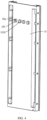
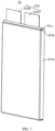
- the cell assembly 20 includes a plurality of cells 21 stacked in a second direction Y.
- the cell 21 includes a cell housing 211, an electrode assembly (not shown in the figure) disposed in the cell housing 211, and an electrode terminal 212 connected to the electrode assembly and led out of the cell housing 211.
- the electrode assembly includes a wound structure formed by a positive electrode plate, a negative electrode plate, and a separator through winding.
- the electrode assembly may alternatively be of a laminated structure, that is, the positive electrode plate, the separator, and the negative electrode plate are sequentially stacked to form an electrode assembly unit, and then a plurality of electrode assembly units are stacked to form the electrode assembly.
- the second direction Y is perpendicular to the first direction X.
- the cell housing 211 includes an aluminum-plastic film.
- the cell 21 includes a pouch cell.
- a projection of the circuit board 30 and a projection of a part of the electrode terminal 212 extending from the cell housing 211 overlap, where the third direction Z is perpendicular to the first direction X and the second direction Y.
- the cell housing 211 includes a first portion 211a and a second portion 211b, where the first portion 211a accommodates the electrode assembly, the second portion 211b connects to the first portion 211a, and the electrode terminal 212 extends from the second portion 211b.
- the first portion 211a and the second portion 211b fit to form a third depression 211c.
- the first connecting member 40 is at least partially located in the third depression 211c to use space of the third depression 211c, reducing space occupied by the first connecting member 40.
- the electrode terminal 212 is connected to the circuit board 30 and can conduct heat to the circuit board 30, resulting in high temperature of the circuit board 30.
- the first connecting member 40 is disposed below the circuit board 30, so that heat is dissipated out of the first through hole 10a and the second through hole 10b to an external environment via the first channel 40a, improving heat dissipation for the circuit board 30.
- temperature around the electrode terminal 212 is higher than temperature around the electrode assembly.
- the electrode terminal 212 and the electrode assembly have a great temperature difference, causing damage to the cell 21 under a long-term cycling condition and shortening service life of the battery module 100.
- the first connecting member 40 is disposed in the third depression 211c and is located at a position of the electrode terminal 212, which can take away heat around the electrode terminal 212 and lower temperature of the electrode terminal 212 of the cell 21 in a timely manner, thereby reducing temperature difference between the electrode terminal 212 and the electrode assembly and prolonging service life of the battery module 100.
- the circuit board 30 is provided with an electronic component, and the first connecting member 40 can further improve heat dissipation for the electronic component, prolonging service life of the electronic component and the circuit board 30.
- the electrode terminal 212 is provided with a welding portion 212a extending out of the cell housing 211, where the welding portion 212a is formed by the electrode terminal 212 through bending.
- the electrode terminals 212 of adjacent cells 21 are bent toward each other and are connected to the circuit board 30.
- the electrode terminal 212 includes a first terminal 212b and a second terminal 212c, the first terminal 212b and the second terminal 212c are opposite in polarity, one of the first terminal 212b and the second terminal 212c is a positive electrode terminal, and the other is a negative electrode terminal.
- a projection of the first terminal 212b of a cell 21 and a projection of the second terminal 212c of an adjacent cell 21 at least partially overlap.
- the third direction Z is perpendicular to the first direction X and the second direction Y.
- the first terminal 212b and the second terminal 212c of adjacent cells are bent toward each other, and the welding portion 212a of the first terminal 212b and the welding portion 212a of the second terminal 212c are stacked and connected with each other.
- the welding portions 212a of adjacent cells 21 are connected with each other, so that the welding portions 212a are connected to the circuit board 30, reducing steps of a manufacture process.
- the projection of the first terminal 212b of the cell 21 and a projection of the first terminal 212b of the adjacent cell 21 may also at least partially overlap; and the first terminal 212b of the cell 21 and the first terminal 212b of the adjacent cell 21 are connected through the circuit board 30 to implement parallel connection between the cells 21.
- the thermally conductive member connects the first connecting member 40 and the electrode terminal 212 and transfers heat of the electrode terminal 212 to the first connecting member 40.
- the circuit board 30 is provided with a plurality of groups of communicating holes disposed in the first direction X, where each group of the communicating holes includes a plurality of third through holes 31, and the plurality of third through holes 31 are disposed in the second direction Y. the third through hole 31 extends in the first direction X.
- the electrode terminal 212 passes through the third through hole 31 and connects to the circuit board 30 through the welding portion 212a.
- the welding portion 212a and the circuit board 30 are connected through welding, where the welding includes laser welding, ultrasonic welding, and the like.
- the welding portion 212a and the circuit board 30 may alternatively be connected through another manner such as a conductive adhesive.
- the circuit board 30 may be a circuit board with a battery management system to implement intelligent management and maintenance of all battery units, reduce overcharge and over discharge of a battery, prolong service life of the battery, and monitor a condition of the battery.
- the circuit board 30 includes a conductive sheet (not shown in the figure), where the welding portion 212a is welded to the conductive sheet.
- the first connecting member 40 when observed in a direction opposite to the third direction Z, is disposed between adjacent third through holes 31, implementing better heat dissipation for the welding portions 212a located on two sides of the first connecting member 40.
- a projection of the first connecting member 40 is located between projections of adjacent third through holes 31.
- the projection of the first connecting member 40 and the projection of the third through hole 31 are spaced apart from each other, reducing interference between the first connecting member 40 and the electrode terminal 212.
- the first connecting member 40 includes a thermally conductive material, for example, aluminum.
- the first connecting member 40 includes a thermally conductive metal material and a thermally conductive insulation material, where the insulation material may cover an outer surface of the thermally conductive metal material to enhance insulation between the first connecting member 40, the cell, and the circuit board.
- two ends of the first connecting member 40 protrude out of the circuit board 30, facilitating assembly and reducing interference between the circuit board 30 and the first connecting member 40.
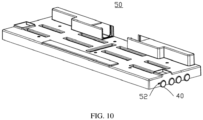
- the battery module 100 further includes a first structural member 50, where the first structural member 50 includes a top plate 50a and a side plate 50b connecting to a peripheral side of the top plate 50a, the top plate 50a and the side plate 50b form a fourth depression 51, and the circuit board 30 is disposed in the fourth depression 51.
- the side plate 50b is provided with a first opening 52 and a second opening 53, where the first opening 52 and the second opening 53 may be disposed in the first direction X.
- One end of the first connecting member 40 is disposed at the first opening 52, and another end thereof is disposed at the second opening 53.
- the circuit board 30 is disposed between the top plate 50a and the first connecting member 40, and the first connecting member 40 is at least partially disposed in the fourth depression 51 to limit the circuit board 30 in the fourth depression 51.
- the projection of the first connecting member 40 and a projection of the side plate 50b partially overlap, enabling the first connecting member 40 to be partially disposed in the fourth depression 51.
- the projection of the first connecting member 40 and the projection of the side plate 50b overlap, so that the first connecting member 40 is entirely disposed in the fourth depression 51.
- first connecting member 40 protrude out of the side plate 50b and are connected to the first protrusion 111 and the second protrusion 121, facilitating limitation on a position of the first connecting member 40.
- an insulation layer is provided in the fourth depression 51 to bond and fasten the circuit board 30, the first connecting member 40, and the first structural member 50.
- the insulation layer may be formed of an insulation material cured after being injected into the fourth depression 51.
- the insulation material includes at least one of a thermally conductive adhesive or a potting adhesive.
- the first connecting member 40 is disposed at the first opening 52 and the second opening 53 through a third adhesive.
- the third adhesive includes a sealant.
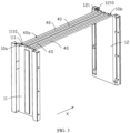
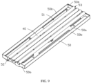
- the battery module 100 includes a second connecting member 60.
- the second connecting member 60 connects to the first connecting member 40, and surfaces of the first connecting member 40 and the second connecting member 60 are provided with an insulation layer, reducing a risk of short circuit between the first connecting member 40 and the second connecting member 60 and the cell 21 and the circuit board 30.
- the second connecting member 60 includes a first component 61, and the first connecting member 40 and the first component 61 are disposed in the third direction Z.
- the first component 61 is disposed between adjacent cells 21, implementing heat dissipation for the adjacent cells 21.
- a projection of the first component 61 and a projection of the cell housing 211 at least partially overlap.
- the projection of the first component 61 is located in a projection area of the cell housing 211.
- the first component 61 being disposed between the adjacent cells 21 enables two surfaces of the cell 21 disposed in the second direction Y both to be in contact connection with the first component 61 and the first component 61 to cover two surfaces of the cell housing 211, increasing a contact area between the first component 61 and the cell housing 211 and improving heat dissipation for the adjacent cells 21.
- the first component 61 is bonded to the cell housing 211 through a fourth adhesive 61a.
- the second connecting member 60 further includes a second component 62, where the second component 62 connects to the first component 61.
- the second component 62 extends from between adjacent cells 21 and is bent toward the cell 21, enabling the second component 62 to be in contact connection with the cell housing 211.
- a projection of the second component 62 and a projection of the cell 21 at least partially overlap.
- the second component 62 being in contact connection with the cell housing 211 increases a contact area between the second connecting member 60 and the cell housing 211, so that heat is conducted to the second component 62 through the cell housing 211 and then conducted to the first connecting member 40 through the second component 62, thereby improving heat dissipation for the cell 21.
- the second component 62 is in contact connection with the housing assembly 10, so that heat is transferred to the housing assembly 10 and is dissipated by the housing assembly 10, thereby further improving heat dissipation for the battery module 100.
- the first component 61 includes a first connecting portion 611 and a second connecting portion 612.
- the first connecting portion 611 and the second connecting portion 612 connect to the first connecting member 40.
- the first connecting portion 611 and the second connecting portion 612 are disposed opposite each other in the second direction Y, where the first connecting portion 611 is in contact connection with one of two adjacent cells 21, and the second connecting portion 612 is in contact connection with the other of the two adjacent cells 21.
- the second component 62 includes a third connecting portion 621 and a fourth connecting portion 622.
- the third connecting portion 621 connects to the first connecting portion 611 and extends from between adjacent cells 21.
- the third connecting portion 621 is bent toward a cell 21 connected to the first connecting portion 611 and is in contact connection with the cell 21.
- the fourth connecting portion 622 connects to the second connecting portion 612 and extends from between adjacent cells 21.
- the third connecting portion 621 is bent toward a cell 21 connected to the second connecting portion 612 and is in contact connection with the cell 21.
- a contact area between the second component 62 and the adjacent cells 21 is further increased, thereby further improving heat dissipation for the cell 21.
- the cell housing 211 includes a first side face 21a, a second side face 21b, and a third side face 21c.
- the first connecting portion 611 connects to a plurality of third connecting portions 621
- the second connecting portion 612 connects to a plurality of fourth connecting portions 622.
- One of the third connecting portions 621 and one of the fourth connecting portions 622 extend from between adjacent cells 21 and are in contact connection with the first side face 21a, another one of the third connecting portions 621 and another one of the fourth connecting portions 622 extend from between adjacent cells 21 and are in contact connection with the second side face 21b, still another one of the third connecting portions 621 and still another one of the fourth connecting portions 622 extend from between adjacent cells 21 and are in contact connection with the third side face 21c, and the second component 62 is disposed at the periphery of the cell housing 211, further improving heat dissipation for the cell 21.
- the third connecting portions 621 and the fourth connecting portions 622 may be connected to the first housing 13 to transfer heat to the first housing 13, further improving heat dissipation for the battery module 100.
- first connecting member 40 and the second connecting member 60 are integrally formed through bending to enhance structural strength of the first connecting member 40 and the second connecting member 60.
- first connecting member 40 and the second connecting member 60 are an aluminum shell.
- this application further provides an electric device 200 using the foregoing battery module 100.
- the electric device 200 in this application may be, but is not limited to, a drone, a backup power source, an electric automobile, an electric motorcycle, an electric motor bicycle, an electric tool, or a large household battery.
Landscapes
- Chemical & Material Sciences (AREA)
- Chemical Kinetics & Catalysis (AREA)
- Electrochemistry (AREA)
- General Chemical & Material Sciences (AREA)
- Engineering & Computer Science (AREA)
- Manufacturing & Machinery (AREA)
- Inorganic Chemistry (AREA)
- Battery Mounting, Suspending (AREA)
- Secondary Cells (AREA)
Applications Claiming Priority (1)
| Application Number | Priority Date | Filing Date | Title |
|---|---|---|---|
| CN202111385544.0A CN114094244B (zh) | 2021-11-22 | 2021-11-22 | 电池组及用电设备 |
Publications (2)
| Publication Number | Publication Date |
|---|---|
| EP4184663A1 true EP4184663A1 (de) | 2023-05-24 |
| EP4184663B1 EP4184663B1 (de) | 2024-10-02 |
Family
ID=80302686
Family Applications (1)
| Application Number | Title | Priority Date | Filing Date |
|---|---|---|---|
| EP22208754.6A Active EP4184663B1 (de) | 2021-11-22 | 2022-11-22 | Batteriemodul und elektrische vorrichtung |
Country Status (3)
| Country | Link |
|---|---|
| US (1) | US20230163385A1 (de) |
| EP (1) | EP4184663B1 (de) |
| CN (1) | CN114094244B (de) |
Families Citing this family (8)
| Publication number | Priority date | Publication date | Assignee | Title |
|---|---|---|---|---|
| CN115425321A (zh) * | 2022-08-30 | 2022-12-02 | 厦门新能达科技有限公司 | 电池组和用电设备 |
| CN115663367A (zh) * | 2022-10-14 | 2023-01-31 | 厦门新能达科技有限公司 | 电化学装置及用电设备 |
| CN119678302A (zh) * | 2022-10-31 | 2025-03-21 | 厦门新能达科技有限公司 | 电池组和用电设备 |
| CN115513561A (zh) * | 2022-10-31 | 2022-12-23 | 厦门新能达科技有限公司 | 电池包、充电系统及用电设备 |
| CN115995646B (zh) * | 2023-01-17 | 2025-12-19 | 厦门新能达科技有限公司 | 电池组及用电设备 |
| CN119678293A (zh) * | 2023-01-17 | 2025-03-21 | 厦门新能达科技有限公司 | 电池组和用电设备 |
| CN116169423A (zh) * | 2023-01-17 | 2023-05-26 | 厦门新能达科技有限公司 | 电池组及用电设备 |
| CN116387727A (zh) * | 2023-03-31 | 2023-07-04 | 厦门新能达科技有限公司 | 电池组和用电设备 |
Citations (4)
| Publication number | Priority date | Publication date | Assignee | Title |
|---|---|---|---|---|
| JP2011258540A (ja) * | 2010-06-08 | 2011-12-22 | Samsung Sdi Co Ltd | バッテリーパック |
| AT511666B1 (de) * | 2011-06-30 | 2015-05-15 | Avl List Gmbh | Wiederaufladbare elektrische batterie |
| US20190173067A1 (en) * | 2016-10-14 | 2019-06-06 | Denso Corporation | Connection member, electric component unit, and battery device |
| US20210320385A1 (en) * | 2018-12-26 | 2021-10-14 | Lg Chem, Ltd. | Battery module comprising inner cover |
Family Cites Families (20)
| Publication number | Priority date | Publication date | Assignee | Title |
|---|---|---|---|---|
| US8852778B2 (en) * | 2009-04-30 | 2014-10-07 | Lg Chem, Ltd. | Battery systems, battery modules, and method for cooling a battery module |
| US8399118B2 (en) * | 2009-07-29 | 2013-03-19 | Lg Chem, Ltd. | Battery module and method for cooling the battery module |
| US10312554B2 (en) * | 2014-01-28 | 2019-06-04 | Ford Global Technologies, Llc | Battery cooling channel with integrated cell retention features |
| KR102211192B1 (ko) * | 2014-05-30 | 2021-02-02 | 에스케이이노베이션 주식회사 | 단위전지모듈, 전지모듈과 전지팩 및 이들의 제조방법 |
| KR102022590B1 (ko) * | 2015-09-21 | 2019-09-18 | 주식회사 엘지화학 | 배터리 모듈 |
| KR20170060451A (ko) * | 2015-11-24 | 2017-06-01 | 삼성에스디아이 주식회사 | 배터리 팩 |
| KR20180013460A (ko) * | 2016-07-29 | 2018-02-07 | 박동식 | 배터리 장치 |
| CN110800154B (zh) * | 2017-04-10 | 2023-04-28 | 允能有限公司 | 一种带有热管理设计电池模块、电池装置与电池系统 |
| KR102523702B1 (ko) * | 2018-07-03 | 2023-04-19 | 주식회사 엘지에너지솔루션 | 배터리 모듈 |
| CN208738326U (zh) * | 2018-09-13 | 2019-04-12 | 宁德时代新能源科技股份有限公司 | 电池模组以及电池包 |
| KR102312415B1 (ko) * | 2018-09-13 | 2021-10-12 | 주식회사 엘지에너지솔루션 | 배터리 모듈, 이러한 배터리 모듈을 포함하는 배터리 팩 및 이러한 배터리 팩을 포함하는 자동차 |
| CN111653697B (zh) * | 2019-03-04 | 2021-08-13 | 东莞新能安科技有限公司 | 包装壳体及电池组 |
| AU2020236020A1 (en) * | 2019-03-14 | 2021-10-28 | Generac Power Systems, Inc. | Battery module thermal management |
| US11355796B2 (en) * | 2019-04-22 | 2022-06-07 | Shahriyar Hekmat | Thermal management system for battery module |
| CN210136918U (zh) * | 2019-07-22 | 2020-03-10 | 宁德时代新能源科技股份有限公司 | 冷却装置及电池模组 |
| CN212412126U (zh) * | 2020-06-08 | 2021-01-26 | 江铃汽车集团有限公司 | 一种软包电池及汽车 |
| CN213752868U (zh) * | 2020-11-30 | 2021-07-20 | 东莞新能安科技有限公司 | 电池组、电池包和用电装置 |
| CN112787043B (zh) * | 2021-01-29 | 2022-11-08 | 东莞新能德科技有限公司 | 电池模组以及用电装置 |
| CN113206320B (zh) * | 2021-04-29 | 2023-07-28 | 东莞新能安科技有限公司 | 一种电池组以及用电设备 |
| CN113517505B (zh) * | 2021-05-21 | 2025-09-26 | 宁德新能源科技有限公司 | 电池组件和用电设备 |
-
2021
- 2021-11-22 CN CN202111385544.0A patent/CN114094244B/zh active Active
-
2022
- 2022-11-21 US US17/991,341 patent/US20230163385A1/en active Pending
- 2022-11-22 EP EP22208754.6A patent/EP4184663B1/de active Active
Patent Citations (4)
| Publication number | Priority date | Publication date | Assignee | Title |
|---|---|---|---|---|
| JP2011258540A (ja) * | 2010-06-08 | 2011-12-22 | Samsung Sdi Co Ltd | バッテリーパック |
| AT511666B1 (de) * | 2011-06-30 | 2015-05-15 | Avl List Gmbh | Wiederaufladbare elektrische batterie |
| US20190173067A1 (en) * | 2016-10-14 | 2019-06-06 | Denso Corporation | Connection member, electric component unit, and battery device |
| US20210320385A1 (en) * | 2018-12-26 | 2021-10-14 | Lg Chem, Ltd. | Battery module comprising inner cover |
Also Published As
| Publication number | Publication date |
|---|---|
| CN114094244B (zh) | 2024-08-27 |
| US20230163385A1 (en) | 2023-05-25 |
| CN114094244A (zh) | 2022-02-25 |
| EP4184663B1 (de) | 2024-10-02 |
Similar Documents
| Publication | Publication Date | Title |
|---|---|---|
| EP4184663B1 (de) | Batteriemodul und elektrische vorrichtung | |
| US12148907B2 (en) | Battery pack | |
| EP3460867B1 (de) | Batteriedose | |
| WO2020143178A1 (zh) | 电池包、车辆和储能装置 | |
| CN115425321A (zh) | 电池组和用电设备 | |
| EP4439802A1 (de) | Batteriepack, verfahren zur herstellung eines batteriepacks und elektrische vorrichtung | |
| CN219873741U (zh) | 热管理部件、电池及用电设备 | |
| EP4407751B1 (de) | Batteriepack und elektrische vorrichtung | |
| WO2013002090A1 (ja) | 電源装置及びこれを備える車両並びに電源装置の製造方法 | |
| WO2021249272A1 (zh) | 一种电池包及电动车 | |
| CN204303901U (zh) | 电池极耳连接结构及包含该连接结构的软包装电池模组 | |
| WO2021149299A1 (ja) | 電源装置とこの電源装置を備える電動車両及び蓄電装置 | |
| US20130157101A1 (en) | Battery assembly having a thermal management system | |
| CN113314784A (zh) | 集成液冷的动力电池模组 | |
| CN209658275U (zh) | 一种软包模组结构 | |
| US20250372799A1 (en) | Pressure relief assembly, battery module, battery pack, and powered device | |
| WO2025055550A1 (zh) | 一种电容模组及功率变换器 | |
| CN218299941U (zh) | 电池模组及电池包 | |
| CN214313319U (zh) | 一种无模组式的电池系统结构、电池包及电动车 | |
| CN215342709U (zh) | 集成液冷的动力电池模组 | |
| CN221201430U (zh) | 电池模组、电池包及用电设备 | |
| CN220984622U (zh) | 一种电池包 | |
| CN222838908U (zh) | 一种液冷电池包 | |
| CN223052348U (zh) | 一种圆柱电池集成装置 | |
| CN222953264U (zh) | 一种电池模组、电池包及新能源汽车 |
Legal Events
| Date | Code | Title | Description |
|---|---|---|---|
| PUAI | Public reference made under article 153(3) epc to a published international application that has entered the european phase |
Free format text: ORIGINAL CODE: 0009012 |
|
| STAA | Information on the status of an ep patent application or granted ep patent |
Free format text: STATUS: REQUEST FOR EXAMINATION WAS MADE |
|
| 17P | Request for examination filed |
Effective date: 20221122 |
|
| AK | Designated contracting states |
Kind code of ref document: A1 Designated state(s): AL AT BE BG CH CY CZ DE DK EE ES FI FR GB GR HR HU IE IS IT LI LT LU LV MC ME MK MT NL NO PL PT RO RS SE SI SK SM TR |
|
| GRAP | Despatch of communication of intention to grant a patent |
Free format text: ORIGINAL CODE: EPIDOSNIGR1 |
|
| STAA | Information on the status of an ep patent application or granted ep patent |
Free format text: STATUS: GRANT OF PATENT IS INTENDED |
|
| INTG | Intention to grant announced |
Effective date: 20240422 |
|
| RIN1 | Information on inventor provided before grant (corrected) |
Inventor name: YANG, PENGCHENG Inventor name: PENG, FANGGUI |
|
| GRAS | Grant fee paid |
Free format text: ORIGINAL CODE: EPIDOSNIGR3 |
|
| GRAA | (expected) grant |
Free format text: ORIGINAL CODE: 0009210 |
|
| STAA | Information on the status of an ep patent application or granted ep patent |
Free format text: STATUS: THE PATENT HAS BEEN GRANTED |
|
| P01 | Opt-out of the competence of the unified patent court (upc) registered |
Free format text: CASE NUMBER: APP_44699/2024 Effective date: 20240801 |
|
| AK | Designated contracting states |
Kind code of ref document: B1 Designated state(s): AL AT BE BG CH CY CZ DE DK EE ES FI FR GB GR HR HU IE IS IT LI LT LU LV MC ME MK MT NL NO PL PT RO RS SE SI SK SM TR |
|
| REG | Reference to a national code |
Ref country code: GB Ref legal event code: FG4D |
|
| REG | Reference to a national code |
Ref country code: CH Ref legal event code: EP |
|
| REG | Reference to a national code |
Ref country code: IE Ref legal event code: FG4D |
|
| REG | Reference to a national code |
Ref country code: DE Ref legal event code: R096 Ref document number: 602022006505 Country of ref document: DE |
|
| REG | Reference to a national code |
Ref country code: NL Ref legal event code: FP |
|
| PGFP | Annual fee paid to national office [announced via postgrant information from national office to epo] |
Ref country code: DE Payment date: 20241105 Year of fee payment: 3 |
|
| PGFP | Annual fee paid to national office [announced via postgrant information from national office to epo] |
Ref country code: FR Payment date: 20241111 Year of fee payment: 3 |
|
| REG | Reference to a national code |
Ref country code: LT Ref legal event code: MG9D |
|
| REG | Reference to a national code |
Ref country code: AT Ref legal event code: MK05 Ref document number: 1729126 Country of ref document: AT Kind code of ref document: T Effective date: 20241002 |
|
| PG25 | Lapsed in a contracting state [announced via postgrant information from national office to epo] |
Ref country code: IS Free format text: LAPSE BECAUSE OF FAILURE TO SUBMIT A TRANSLATION OF THE DESCRIPTION OR TO PAY THE FEE WITHIN THE PRESCRIBED TIME-LIMIT Effective date: 20250202 Ref country code: HR Free format text: LAPSE BECAUSE OF FAILURE TO SUBMIT A TRANSLATION OF THE DESCRIPTION OR TO PAY THE FEE WITHIN THE PRESCRIBED TIME-LIMIT Effective date: 20241002 Ref country code: PT Free format text: LAPSE BECAUSE OF FAILURE TO SUBMIT A TRANSLATION OF THE DESCRIPTION OR TO PAY THE FEE WITHIN THE PRESCRIBED TIME-LIMIT Effective date: 20250203 |
|
| PG25 | Lapsed in a contracting state [announced via postgrant information from national office to epo] |
Ref country code: FI Free format text: LAPSE BECAUSE OF FAILURE TO SUBMIT A TRANSLATION OF THE DESCRIPTION OR TO PAY THE FEE WITHIN THE PRESCRIBED TIME-LIMIT Effective date: 20241002 |
|
| PG25 | Lapsed in a contracting state [announced via postgrant information from national office to epo] |
Ref country code: BG Free format text: LAPSE BECAUSE OF FAILURE TO SUBMIT A TRANSLATION OF THE DESCRIPTION OR TO PAY THE FEE WITHIN THE PRESCRIBED TIME-LIMIT Effective date: 20241002 |
|
| PG25 | Lapsed in a contracting state [announced via postgrant information from national office to epo] |
Ref country code: ES Free format text: LAPSE BECAUSE OF FAILURE TO SUBMIT A TRANSLATION OF THE DESCRIPTION OR TO PAY THE FEE WITHIN THE PRESCRIBED TIME-LIMIT Effective date: 20241002 |
|
| PG25 | Lapsed in a contracting state [announced via postgrant information from national office to epo] |
Ref country code: NO Free format text: LAPSE BECAUSE OF FAILURE TO SUBMIT A TRANSLATION OF THE DESCRIPTION OR TO PAY THE FEE WITHIN THE PRESCRIBED TIME-LIMIT Effective date: 20250102 |
|
| PG25 | Lapsed in a contracting state [announced via postgrant information from national office to epo] |
Ref country code: GR Free format text: LAPSE BECAUSE OF FAILURE TO SUBMIT A TRANSLATION OF THE DESCRIPTION OR TO PAY THE FEE WITHIN THE PRESCRIBED TIME-LIMIT Effective date: 20250103 Ref country code: AT Free format text: LAPSE BECAUSE OF FAILURE TO SUBMIT A TRANSLATION OF THE DESCRIPTION OR TO PAY THE FEE WITHIN THE PRESCRIBED TIME-LIMIT Effective date: 20241002 Ref country code: LV Free format text: LAPSE BECAUSE OF FAILURE TO SUBMIT A TRANSLATION OF THE DESCRIPTION OR TO PAY THE FEE WITHIN THE PRESCRIBED TIME-LIMIT Effective date: 20241002 |
|
| PG25 | Lapsed in a contracting state [announced via postgrant information from national office to epo] |
Ref country code: CZ Free format text: LAPSE BECAUSE OF FAILURE TO SUBMIT A TRANSLATION OF THE DESCRIPTION OR TO PAY THE FEE WITHIN THE PRESCRIBED TIME-LIMIT Effective date: 20241002 Ref country code: PL Free format text: LAPSE BECAUSE OF FAILURE TO SUBMIT A TRANSLATION OF THE DESCRIPTION OR TO PAY THE FEE WITHIN THE PRESCRIBED TIME-LIMIT Effective date: 20241002 |
|
| PG25 | Lapsed in a contracting state [announced via postgrant information from national office to epo] |
Ref country code: RS Free format text: LAPSE BECAUSE OF FAILURE TO SUBMIT A TRANSLATION OF THE DESCRIPTION OR TO PAY THE FEE WITHIN THE PRESCRIBED TIME-LIMIT Effective date: 20250102 |
|
| PG25 | Lapsed in a contracting state [announced via postgrant information from national office to epo] |
Ref country code: SM Free format text: LAPSE BECAUSE OF FAILURE TO SUBMIT A TRANSLATION OF THE DESCRIPTION OR TO PAY THE FEE WITHIN THE PRESCRIBED TIME-LIMIT Effective date: 20241002 |
|
| REG | Reference to a national code |
Ref country code: DE Ref legal event code: R097 Ref document number: 602022006505 Country of ref document: DE |
|
| PG25 | Lapsed in a contracting state [announced via postgrant information from national office to epo] |
Ref country code: MC Free format text: LAPSE BECAUSE OF FAILURE TO SUBMIT A TRANSLATION OF THE DESCRIPTION OR TO PAY THE FEE WITHIN THE PRESCRIBED TIME-LIMIT Effective date: 20241002 |
|
| PG25 | Lapsed in a contracting state [announced via postgrant information from national office to epo] |
Ref country code: DK Free format text: LAPSE BECAUSE OF FAILURE TO SUBMIT A TRANSLATION OF THE DESCRIPTION OR TO PAY THE FEE WITHIN THE PRESCRIBED TIME-LIMIT Effective date: 20241002 |
|
| PG25 | Lapsed in a contracting state [announced via postgrant information from national office to epo] |
Ref country code: LU Free format text: LAPSE BECAUSE OF NON-PAYMENT OF DUE FEES Effective date: 20241122 |
|
| PG25 | Lapsed in a contracting state [announced via postgrant information from national office to epo] |
Ref country code: EE Free format text: LAPSE BECAUSE OF FAILURE TO SUBMIT A TRANSLATION OF THE DESCRIPTION OR TO PAY THE FEE WITHIN THE PRESCRIBED TIME-LIMIT Effective date: 20241002 |
|
| PG25 | Lapsed in a contracting state [announced via postgrant information from national office to epo] |
Ref country code: RO Free format text: LAPSE BECAUSE OF FAILURE TO SUBMIT A TRANSLATION OF THE DESCRIPTION OR TO PAY THE FEE WITHIN THE PRESCRIBED TIME-LIMIT Effective date: 20241002 |
|
| PG25 | Lapsed in a contracting state [announced via postgrant information from national office to epo] |
Ref country code: SK Free format text: LAPSE BECAUSE OF FAILURE TO SUBMIT A TRANSLATION OF THE DESCRIPTION OR TO PAY THE FEE WITHIN THE PRESCRIBED TIME-LIMIT Effective date: 20241002 |
|
| PG25 | Lapsed in a contracting state [announced via postgrant information from national office to epo] |
Ref country code: IT Free format text: LAPSE BECAUSE OF FAILURE TO SUBMIT A TRANSLATION OF THE DESCRIPTION OR TO PAY THE FEE WITHIN THE PRESCRIBED TIME-LIMIT Effective date: 20241002 |
|
| PLBE | No opposition filed within time limit |
Free format text: ORIGINAL CODE: 0009261 |
|
| STAA | Information on the status of an ep patent application or granted ep patent |
Free format text: STATUS: NO OPPOSITION FILED WITHIN TIME LIMIT |
|
| REG | Reference to a national code |
Ref country code: BE Ref legal event code: MM Effective date: 20241130 |
|
| PG25 | Lapsed in a contracting state [announced via postgrant information from national office to epo] |
Ref country code: SE Free format text: LAPSE BECAUSE OF FAILURE TO SUBMIT A TRANSLATION OF THE DESCRIPTION OR TO PAY THE FEE WITHIN THE PRESCRIBED TIME-LIMIT Effective date: 20241002 |
|
| 26N | No opposition filed |
Effective date: 20250703 |
|
| PG25 | Lapsed in a contracting state [announced via postgrant information from national office to epo] |
Ref country code: BE Free format text: LAPSE BECAUSE OF NON-PAYMENT OF DUE FEES Effective date: 20241130 |
|
| PG25 | Lapsed in a contracting state [announced via postgrant information from national office to epo] |
Ref country code: IE Free format text: LAPSE BECAUSE OF NON-PAYMENT OF DUE FEES Effective date: 20241122 |
|
| REG | Reference to a national code |
Ref country code: NL Ref legal event code: PD Owner name: NINGDE AMPEREX TECHNOLOGY LIMITED; CN Free format text: DETAILS ASSIGNMENT: CHANGE OF OWNER(S), ASSIGNMENT; FORMER OWNER NAME: DONGGUAN POWERAMP TECHNOLOGY LIMITED Effective date: 20251024 |
|
| PGFP | Annual fee paid to national office [announced via postgrant information from national office to epo] |
Ref country code: NL Payment date: 20251015 Year of fee payment: 4 |
|
| REG | Reference to a national code |
Ref country code: DE Ref legal event code: R081 Ref document number: 602022006505 Country of ref document: DE Owner name: NINGDE AMPEREX TECHNOLOGY LIMITED, NINGDE, CN Free format text: FORMER OWNER: DONGGUAN POWERAMP TECHNOLOGY LIMITED, DONGGUAN, GUANGDONG, CN |