EP4184563A1 - Temperatursteuerungselement, das in bauteilverpackungen verwendet wird - Google Patents
Temperatursteuerungselement, das in bauteilverpackungen verwendet wird Download PDFInfo
- Publication number
- EP4184563A1 EP4184563A1 EP22188536.1A EP22188536A EP4184563A1 EP 4184563 A1 EP4184563 A1 EP 4184563A1 EP 22188536 A EP22188536 A EP 22188536A EP 4184563 A1 EP4184563 A1 EP 4184563A1
- Authority
- EP
- European Patent Office
- Prior art keywords
- die
- thermal dissipating
- disposed
- package
- temperature control
- Prior art date
- Legal status (The legal status is an assumption and is not a legal conclusion. Google has not performed a legal analysis and makes no representation as to the accuracy of the status listed.)
- Pending
Links
- 239000012530 fluid Substances 0.000 claims description 15
- 229910000679 solder Inorganic materials 0.000 claims description 13
- 239000000463 material Substances 0.000 claims description 10
- 238000001465 metallisation Methods 0.000 claims description 9
- 238000004519 manufacturing process Methods 0.000 claims description 8
- 238000000034 method Methods 0.000 claims description 6
- 238000007789 sealing Methods 0.000 claims description 6
- 238000003491 array Methods 0.000 claims description 5
- RYGMFSIKBFXOCR-UHFFFAOYSA-N Copper Chemical compound [Cu] RYGMFSIKBFXOCR-UHFFFAOYSA-N 0.000 claims description 4
- BQCADISMDOOEFD-UHFFFAOYSA-N Silver Chemical compound [Ag] BQCADISMDOOEFD-UHFFFAOYSA-N 0.000 claims description 4
- 229910045601 alloy Inorganic materials 0.000 claims description 4
- 239000000956 alloy Substances 0.000 claims description 4
- 229910052782 aluminium Inorganic materials 0.000 claims description 4
- XAGFODPZIPBFFR-UHFFFAOYSA-N aluminium Chemical compound [Al] XAGFODPZIPBFFR-UHFFFAOYSA-N 0.000 claims description 4
- 229910052802 copper Inorganic materials 0.000 claims description 4
- 239000010949 copper Substances 0.000 claims description 4
- 229910052709 silver Inorganic materials 0.000 claims description 4
- 239000004332 silver Substances 0.000 claims description 4
- 125000006850 spacer group Chemical group 0.000 claims description 4
- WFKWXMTUELFFGS-UHFFFAOYSA-N tungsten Chemical compound [W] WFKWXMTUELFFGS-UHFFFAOYSA-N 0.000 claims description 4
- 229910052721 tungsten Inorganic materials 0.000 claims description 4
- 239000010937 tungsten Substances 0.000 claims description 4
- PCHJSUWPFVWCPO-UHFFFAOYSA-N gold Chemical compound [Au] PCHJSUWPFVWCPO-UHFFFAOYSA-N 0.000 claims description 3
- 229910052737 gold Inorganic materials 0.000 claims description 3
- 239000010931 gold Substances 0.000 claims description 3
- 230000017525 heat dissipation Effects 0.000 abstract description 6
- 239000004065 semiconductor Substances 0.000 abstract description 4
- BQENMISTWGTJIJ-UHFFFAOYSA-N 2,3,3',4,5-pentachlorobiphenyl Chemical compound ClC1=CC=CC(C=2C(=C(Cl)C(Cl)=C(Cl)C=2)Cl)=C1 BQENMISTWGTJIJ-UHFFFAOYSA-N 0.000 description 10
- 230000000712 assembly Effects 0.000 description 7
- 238000000429 assembly Methods 0.000 description 7
- 238000005516 engineering process Methods 0.000 description 6
- 238000005476 soldering Methods 0.000 description 5
- 239000000853 adhesive Substances 0.000 description 4
- 230000001070 adhesive effect Effects 0.000 description 4
- 238000001816 cooling Methods 0.000 description 4
- 238000009826 distribution Methods 0.000 description 3
- 239000011159 matrix material Substances 0.000 description 3
- XEEYBQQBJWHFJM-UHFFFAOYSA-N Iron Chemical compound [Fe] XEEYBQQBJWHFJM-UHFFFAOYSA-N 0.000 description 2
- PXHVJJICTQNCMI-UHFFFAOYSA-N Nickel Chemical compound [Ni] PXHVJJICTQNCMI-UHFFFAOYSA-N 0.000 description 2
- -1 combinations thereof Substances 0.000 description 2
- 238000000151 deposition Methods 0.000 description 2
- 238000010586 diagram Methods 0.000 description 2
- 239000007788 liquid Substances 0.000 description 2
- 238000013021 overheating Methods 0.000 description 2
- 238000004806 packaging method and process Methods 0.000 description 2
- 239000000758 substrate Substances 0.000 description 2
- 239000003570 air Substances 0.000 description 1
- 230000005540 biological transmission Effects 0.000 description 1
- 239000004020 conductor Substances 0.000 description 1
- 238000013461 design Methods 0.000 description 1
- 230000006866 deterioration Effects 0.000 description 1
- 238000005530 etching Methods 0.000 description 1
- 238000009434 installation Methods 0.000 description 1
- 229910052742 iron Inorganic materials 0.000 description 1
- 238000001459 lithography Methods 0.000 description 1
- 238000004377 microelectronic Methods 0.000 description 1
- 238000012986 modification Methods 0.000 description 1
- 230000004048 modification Effects 0.000 description 1
- 229910052759 nickel Inorganic materials 0.000 description 1
- 230000021715 photosynthesis, light harvesting Effects 0.000 description 1
- 238000007747 plating Methods 0.000 description 1
- 238000005498 polishing Methods 0.000 description 1
- 238000012545 processing Methods 0.000 description 1
Images


Classifications
-
- H—ELECTRICITY
- H01—ELECTRIC ELEMENTS
- H01L—SEMICONDUCTOR DEVICES NOT COVERED BY CLASS H10
- H01L23/00—Details of semiconductor or other solid state devices
- H01L23/34—Arrangements for cooling, heating, ventilating or temperature compensation ; Temperature sensing arrangements
- H01L23/46—Arrangements for cooling, heating, ventilating or temperature compensation ; Temperature sensing arrangements involving the transfer of heat by flowing fluids
- H01L23/473—Arrangements for cooling, heating, ventilating or temperature compensation ; Temperature sensing arrangements involving the transfer of heat by flowing fluids by flowing liquids
-
- H—ELECTRICITY
- H01—ELECTRIC ELEMENTS
- H01L—SEMICONDUCTOR DEVICES NOT COVERED BY CLASS H10
- H01L23/00—Details of semiconductor or other solid state devices
- H01L23/34—Arrangements for cooling, heating, ventilating or temperature compensation ; Temperature sensing arrangements
- H01L23/46—Arrangements for cooling, heating, ventilating or temperature compensation ; Temperature sensing arrangements involving the transfer of heat by flowing fluids
-
- H—ELECTRICITY
- H01—ELECTRIC ELEMENTS
- H01L—SEMICONDUCTOR DEVICES NOT COVERED BY CLASS H10
- H01L21/00—Processes or apparatus adapted for the manufacture or treatment of semiconductor or solid state devices or of parts thereof
- H01L21/02—Manufacture or treatment of semiconductor devices or of parts thereof
- H01L21/04—Manufacture or treatment of semiconductor devices or of parts thereof the devices having at least one potential-jump barrier or surface barrier, e.g. PN junction, depletion layer or carrier concentration layer
- H01L21/50—Assembly of semiconductor devices using processes or apparatus not provided for in a single one of the subgroups H01L21/06 - H01L21/326, e.g. sealing of a cap to a base of a container
- H01L21/56—Encapsulations, e.g. encapsulation layers, coatings
-
- H—ELECTRICITY
- H01—ELECTRIC ELEMENTS
- H01L—SEMICONDUCTOR DEVICES NOT COVERED BY CLASS H10
- H01L23/00—Details of semiconductor or other solid state devices
- H01L23/34—Arrangements for cooling, heating, ventilating or temperature compensation ; Temperature sensing arrangements
- H01L23/36—Selection of materials, or shaping, to facilitate cooling or heating, e.g. heatsinks
- H01L23/367—Cooling facilitated by shape of device
- H01L23/3672—Foil-like cooling fins or heat sinks
-
- H—ELECTRICITY
- H01—ELECTRIC ELEMENTS
- H01L—SEMICONDUCTOR DEVICES NOT COVERED BY CLASS H10
- H01L23/00—Details of semiconductor or other solid state devices
- H01L23/34—Arrangements for cooling, heating, ventilating or temperature compensation ; Temperature sensing arrangements
- H01L23/36—Selection of materials, or shaping, to facilitate cooling or heating, e.g. heatsinks
- H01L23/373—Cooling facilitated by selection of materials for the device or materials for thermal expansion adaptation, e.g. carbon
- H01L23/3735—Laminates or multilayers, e.g. direct bond copper ceramic substrates
-
- H—ELECTRICITY
- H01—ELECTRIC ELEMENTS
- H01L—SEMICONDUCTOR DEVICES NOT COVERED BY CLASS H10
- H01L2224/00—Indexing scheme for arrangements for connecting or disconnecting semiconductor or solid-state bodies and methods related thereto as covered by H01L24/00
- H01L2224/01—Means for bonding being attached to, or being formed on, the surface to be connected, e.g. chip-to-package, die-attach, "first-level" interconnects; Manufacturing methods related thereto
- H01L2224/10—Bump connectors; Manufacturing methods related thereto
- H01L2224/15—Structure, shape, material or disposition of the bump connectors after the connecting process
- H01L2224/16—Structure, shape, material or disposition of the bump connectors after the connecting process of an individual bump connector
- H01L2224/161—Disposition
- H01L2224/16151—Disposition the bump connector connecting between a semiconductor or solid-state body and an item not being a semiconductor or solid-state body, e.g. chip-to-substrate, chip-to-passive
- H01L2224/16221—Disposition the bump connector connecting between a semiconductor or solid-state body and an item not being a semiconductor or solid-state body, e.g. chip-to-substrate, chip-to-passive the body and the item being stacked
- H01L2224/16225—Disposition the bump connector connecting between a semiconductor or solid-state body and an item not being a semiconductor or solid-state body, e.g. chip-to-substrate, chip-to-passive the body and the item being stacked the item being non-metallic, e.g. insulating substrate with or without metallisation
- H01L2224/16227—Disposition the bump connector connecting between a semiconductor or solid-state body and an item not being a semiconductor or solid-state body, e.g. chip-to-substrate, chip-to-passive the body and the item being stacked the item being non-metallic, e.g. insulating substrate with or without metallisation the bump connector connecting to a bond pad of the item
-
- H—ELECTRICITY
- H01—ELECTRIC ELEMENTS
- H01L—SEMICONDUCTOR DEVICES NOT COVERED BY CLASS H10
- H01L2224/00—Indexing scheme for arrangements for connecting or disconnecting semiconductor or solid-state bodies and methods related thereto as covered by H01L24/00
- H01L2224/01—Means for bonding being attached to, or being formed on, the surface to be connected, e.g. chip-to-package, die-attach, "first-level" interconnects; Manufacturing methods related thereto
- H01L2224/26—Layer connectors, e.g. plate connectors, solder or adhesive layers; Manufacturing methods related thereto
- H01L2224/28—Structure, shape, material or disposition of the layer connectors prior to the connecting process
- H01L2224/29—Structure, shape, material or disposition of the layer connectors prior to the connecting process of an individual layer connector
- H01L2224/29001—Core members of the layer connector
- H01L2224/2902—Disposition
- H01L2224/29034—Disposition the layer connector covering only portions of the surface to be connected
- H01L2224/29035—Disposition the layer connector covering only portions of the surface to be connected covering only the peripheral area of the surface to be connected
-
- H—ELECTRICITY
- H01—ELECTRIC ELEMENTS
- H01L—SEMICONDUCTOR DEVICES NOT COVERED BY CLASS H10
- H01L2224/00—Indexing scheme for arrangements for connecting or disconnecting semiconductor or solid-state bodies and methods related thereto as covered by H01L24/00
- H01L2224/01—Means for bonding being attached to, or being formed on, the surface to be connected, e.g. chip-to-package, die-attach, "first-level" interconnects; Manufacturing methods related thereto
- H01L2224/26—Layer connectors, e.g. plate connectors, solder or adhesive layers; Manufacturing methods related thereto
- H01L2224/31—Structure, shape, material or disposition of the layer connectors after the connecting process
- H01L2224/32—Structure, shape, material or disposition of the layer connectors after the connecting process of an individual layer connector
- H01L2224/321—Disposition
- H01L2224/32151—Disposition the layer connector connecting between a semiconductor or solid-state body and an item not being a semiconductor or solid-state body, e.g. chip-to-substrate, chip-to-passive
- H01L2224/32221—Disposition the layer connector connecting between a semiconductor or solid-state body and an item not being a semiconductor or solid-state body, e.g. chip-to-substrate, chip-to-passive the body and the item being stacked
-
- H—ELECTRICITY
- H01—ELECTRIC ELEMENTS
- H01L—SEMICONDUCTOR DEVICES NOT COVERED BY CLASS H10
- H01L2224/00—Indexing scheme for arrangements for connecting or disconnecting semiconductor or solid-state bodies and methods related thereto as covered by H01L24/00
- H01L2224/73—Means for bonding being of different types provided for in two or more of groups H01L2224/10, H01L2224/18, H01L2224/26, H01L2224/34, H01L2224/42, H01L2224/50, H01L2224/63, H01L2224/71
- H01L2224/732—Location after the connecting process
- H01L2224/73251—Location after the connecting process on different surfaces
- H01L2224/73253—Bump and layer connectors
-
- H—ELECTRICITY
- H01—ELECTRIC ELEMENTS
- H01L—SEMICONDUCTOR DEVICES NOT COVERED BY CLASS H10
- H01L23/00—Details of semiconductor or other solid state devices
- H01L23/34—Arrangements for cooling, heating, ventilating or temperature compensation ; Temperature sensing arrangements
- H01L23/36—Selection of materials, or shaping, to facilitate cooling or heating, e.g. heatsinks
- H01L23/373—Cooling facilitated by selection of materials for the device or materials for thermal expansion adaptation, e.g. carbon
- H01L23/3736—Metallic materials
-
- H—ELECTRICITY
- H01—ELECTRIC ELEMENTS
- H01L—SEMICONDUCTOR DEVICES NOT COVERED BY CLASS H10
- H01L24/00—Arrangements for connecting or disconnecting semiconductor or solid-state bodies; Methods or apparatus related thereto
- H01L24/01—Means for bonding being attached to, or being formed on, the surface to be connected, e.g. chip-to-package, die-attach, "first-level" interconnects; Manufacturing methods related thereto
- H01L24/10—Bump connectors ; Manufacturing methods related thereto
- H01L24/15—Structure, shape, material or disposition of the bump connectors after the connecting process
- H01L24/16—Structure, shape, material or disposition of the bump connectors after the connecting process of an individual bump connector
-
- H—ELECTRICITY
- H01—ELECTRIC ELEMENTS
- H01L—SEMICONDUCTOR DEVICES NOT COVERED BY CLASS H10
- H01L24/00—Arrangements for connecting or disconnecting semiconductor or solid-state bodies; Methods or apparatus related thereto
- H01L24/01—Means for bonding being attached to, or being formed on, the surface to be connected, e.g. chip-to-package, die-attach, "first-level" interconnects; Manufacturing methods related thereto
- H01L24/26—Layer connectors, e.g. plate connectors, solder or adhesive layers; Manufacturing methods related thereto
- H01L24/28—Structure, shape, material or disposition of the layer connectors prior to the connecting process
- H01L24/29—Structure, shape, material or disposition of the layer connectors prior to the connecting process of an individual layer connector
-
- H—ELECTRICITY
- H01—ELECTRIC ELEMENTS
- H01L—SEMICONDUCTOR DEVICES NOT COVERED BY CLASS H10
- H01L24/00—Arrangements for connecting or disconnecting semiconductor or solid-state bodies; Methods or apparatus related thereto
- H01L24/01—Means for bonding being attached to, or being formed on, the surface to be connected, e.g. chip-to-package, die-attach, "first-level" interconnects; Manufacturing methods related thereto
- H01L24/26—Layer connectors, e.g. plate connectors, solder or adhesive layers; Manufacturing methods related thereto
- H01L24/31—Structure, shape, material or disposition of the layer connectors after the connecting process
- H01L24/32—Structure, shape, material or disposition of the layer connectors after the connecting process of an individual layer connector
-
- H—ELECTRICITY
- H01—ELECTRIC ELEMENTS
- H01L—SEMICONDUCTOR DEVICES NOT COVERED BY CLASS H10
- H01L24/00—Arrangements for connecting or disconnecting semiconductor or solid-state bodies; Methods or apparatus related thereto
- H01L24/73—Means for bonding being of different types provided for in two or more of groups H01L24/10, H01L24/18, H01L24/26, H01L24/34, H01L24/42, H01L24/50, H01L24/63, H01L24/71
Definitions
- Electronic devices such as tablets, computers, copiers, digital cameras, smart phones, control systems and automated teller machines, among others, often employ electronic components such as chip assemblies or integrated circuit (IC) dies that are connected by various interconnect components.
- the chip assemblies or IC dies may include memory, logic, devices, or other IC dies.
- an IC package assembly comprising a temperature control element.
- the temperature control element may be an integral part of the IC package assembly that may assist temperature control of the IC die when in operation. When such IC package assembly with temperature control element is assembled, the thermal dissipation efficiency for the overall IC package is then enhanced.
- an integrated circuit (IC) package includes an IC die disposed on a printed circuit board (PCB), and a temperature control element encasing the IC die.
- the temperature control element includes a plurality of thermal dissipating features disposed on a first surface of the IC die.
- a manifold is disposed on the PCB encasing the plurality of thermal dissipating features disposed on the IC die.
- each of the thermal dissipating features includes a metallic pin fin disposed on a solder bump.
- the metallic pin fin is manufactured from a material selected from copper, aluminum, tungsten, gold, silver, combinations thereof or alloys thereof.
- the plurality of thermal dissipating features is arranged in arrays or matrix.
- a sealing member is disposed between the manifold and the IC die.
- the manifold includes a first sidewall, a second sidewall, and a ceiling disposed between the first and the second sidewall, defining a central cavity that allows the IC die to be encased therein.
- a plenum is defined in a center portion of the ceiling. The plenum allows fluid to flow therethrough from an inlet to an outlet of the plenum.
- a spacer is disposed between the thermal dissipating feature and the manifold.
- the plurality of thermal dissipating features has a circular configuration, a rectangular configuration, or a longitudinal structure. In one example, the thermal dissipating features have different aspect ratios.
- the thermal dissipating features is divided into a first and a second zone disposed on the IC die. The first zone has a higher number of the thermal dissipating features than the thermal dissipating features disposed in the second zone.
- the plurality of the thermal dissipating features has a top surface spaced apart from the manifold.
- the plurality of the thermal dissipating features has a top surface in direct contact with the manifold.
- the IC die has a second surface opposite to the first surface, wherein device structures are formed on the second side of the IC die.
- the temperature control element includes a plurality of thermal dissipating features configured to be disposed on a surface of the IC die.
- a manifold having a plenum is configured to encase the plurality of thermal dissipating features disposed on the IC die.
- each of the thermal dissipating features includes a metallic pin fin disposed on a solder bump.
- the plenum is configured to receive fluid to control temperature of the IC die when in operation.
- Yet another aspect of the technology is directed to a method for manufacturing a temperature control element in an IC package.
- the method includes disposing a plurality of thermal dissipating features on an IC die disposed on a PCB, placing a manifold on the PCB to encase the IC die therein while maintaining the plurality of thermal dissipating features located in a plenum defined in the manifold, and supplying a fluid into the plenum to regulate thermal energy transmitted from the IC die.
- the technology relates generally to a temperature control element that may be utilized to control a temperature of an IC die integrated in an IC packaging assembly.
- the temperature control element may be formed on an IC die to assist temperature control of the IC die when in operation.
- the temperature control element may have a plurality of thermal dissipating features disposed on a first surface of an IC die encased under a manifold to efficiently control and dissipate the thermal energy from the IC die when in operation.
- a second surface opposite to the first surface of the IC die may include a plurality of devices, such as semiconductors transistors, devices, electrical components, circuits, or the like, that may generate thermal energy when in operation.
- the thermal dissipating features may be manufactured from a heat dissipation material to assist dissipating thermal energy generated by the plurality of devices in the IC die during operation. Different configurations of the thermal dissipating features may be utilized to accommodate different device layouts with different thermal energy generation across the substrate in the IC die.
- An IC die includes a temperature control element suitable for three-dimensional IC package with enhanced thermal control and management.
- the temperature control element may assist temperature control of the IC die when in operation.
- the temperature control element may have a plurality of thermal dissipating features disposed on a first surface of the IC die to efficiently control and dissipate the thermal energy from the IC die when in operation.
- a second surface opposite to the first surface of the IC die may include a plurality of devices, such as semiconductors transistors, devices, electrical components, circuits, or the like, that may generate thermal energy when in operation.
- the temperature control element may provide an IC die with high efficiency of heat dissipation that is suitable for 3D IC package structures and requirements.
- FIG. 1 depicts a cross sectional-view of an IC package 100 including an IC die 105 formed on a printed circuit board (PCB) 106.
- PCB printed circuit board
- FIG. 1 only includes one IC die 105, it is noted that one or more IC dies or IC die assemblies may be utilized or disposed on the PCB 106.
- the IC dies and the devices or chip assemblies disposed in the IC package 100 may be in any numbers.
- the IC die 105 utilized herein may be a graphics processing unit (GPU), custom application-specific integrated circuit (ASIC), memory devices, high-bandwidth memory (HBM) components or any other type of devices or stacks.
- GPU graphics processing unit
- ASIC application-specific integrated circuit
- HBM high-bandwidth memory
- the IC die 105 is disposed on the PCB 106 through a plurality of solder balls 108 arranged in a ball grid array (BGA).
- BGA ball grid array
- Other arrangements and connectors may include contacts arranged in a land grid array (LGA), connector pins arranged in a pin grid array (PGA), etc.
- a temperature control element 151 is utilized to encase the IC die 105.
- the temperature control element 151 overlies an adhesive material 152.
- the adhesive material 152 provides a good sealing interface between the temperature control element 151 and the PCB 106.
- the temperature control element 151 includes a manifold 150 having a first side wall 161 and a second sidewall 163 connected by a ceiling 162, forming a substantially U-shape body 164 that defines a central cavity 160 on a bottom side of the manifold 150.
- the central cavity 160 may encase one or more IC dies 105 positioned therein when the temperature control element 151 is placed or mounted on the PCB 106.
- a sealing member 165 may be utilized to seal the interface where the manifold 150 is in contact with the IC die 105.
- the sealing member 165 may be an adhesive material, a O ring, or suitable mechanical attachments that facilitate positioning and securement of the manifold 150 to the IC die 105.
- a plenum 121 may be defined in the ceiling 162 of the manifold 150. The plenum 121 may allow fluid, air, or liquid to be flown therein for temperature control purposes to the IC die 105 when the temperature control element 151 is in place for operation.
- a plurality of thermal dissipating features 120 may be disposed on a first surface 109 of the IC die 105 that may assist dissipating thermal energy from the IC die 105 when IC die 105 is in operation.
- the plurality of thermal dissipating features 120 may be disposed on the first surface 109 of the IC die 105 by plating, depositing or soldering.
- a second surface 111 is formed substantially in paragraph and opposite to the first surface 109 where a plurality of device structures 115 may be disposed to form the IC die 105.
- a metallization layer 110 may be formed on the surface 109 of the IC die 105 to facilitate soldering the plurality of thermal dissipating features 120 thereon.
- the metallization layer 110 may be manufactured from a conductive material, such as copper, aluminum, tungsten, nickel, silver, iron, combinations thereof, alloys thereof or the like.
- each of the thermal dissipating features 120 may include a metallic pin fin 125 disposed on a solder bump 124.
- the solder bump 124 may assist soldering the metallic pin fins 125 onto the first surface 109 of the IC die 105.
- the metallic pin fin 125 may be manufactured from a material that has good thermal dissipation or thermal transmission efficiency. Suitable examples of the materials that may be selected to manufacture the metallic pin fin 125 include copper, aluminum, tungsten, gold, silver, combinations thereof, alloys thereof, or the like.
- the thermal dissipating features 120 may be disposed on the surface 109 of the IC die 105 in the form of one or more arrays or matrices.
- fluid When in operation, fluid may be supplied from an inlet 127 to circulate through the plenum 121 to an outlet 128.
- the fluid as supplied may include liquid, air, or other suitable cooling mediums that may efficiently lower and/or cool the temperature of the IC die 102 with which the fluid is in direct contact.
- the thermal dissipating features 120 such as the metallic pin fins 125 included therein, may increase contact surface area when the fluid is in circulation in the plenum 121 so as to enhance the cooling performance.
- FIGS. 2A-2F depict cross sectional views of an IC package assembly during different stages of implementing the temperature control element on the IC die 105 of FIG. 1 .
- the IC die 105 is soldered on the PCB 106.
- the metallization layer 110 may be disposed on the surface 109 of the IC die 105, as shown in FIG. 2B .
- the metallization layer 110 may be disposed and formed on the surface 109 of the IC die 105 prior to soldering to the PCB 106.
- the metallization layer 110 may be deposited or formed on the IC die 105 as part of the manufacturing steps fulfilled by the IC manufacturing facilities prior to shipping to the IC packaging facility to be soldered on the PCB 106.
- a plurality of the thermal dissipating features 120 is disposed on the surface 109 of the IC die 105.
- the thermal dissipating features 120 may be soldered onto the IC die 105 by the solder bumps 124 included therein.
- the solder bumps 124 may facilitate attaching the metallic pin fins 125 onto the surface 109 of the IC die 105 for temperature control when in operation.
- the sealing member 165 may be disposed on the IC die 105.
- the manifold 150 may be disposed on the PCB 106 through adhesive material 152.
- the manifold 150 is positioned in a manner that allows the central cavity 160 of the manifold 150 to encase the IC die 105 therein while allowing the plurality of thermal dissipating features 120 to be encased in the plenum 121.
- the height of the thermal dissipating features 120 may be controlled in a manner so that a top 129 of the thermal dissipating features 120 may be maintained spaced apart from a bottom surface 130 of the center portion 134 of the ceiling 162. It is noted that different configurations of the thermal dissipating features 120 may be utilized to enhance thermal energy circulation and thermal dissipating efficiency.
- the installation of the temperature control element 151, including the manifold 150 and the thermal dissipating features 120 is then considered completed.
- fluid may be supplied to the plenum 121 to facilitate temperature control of the IC die 105 through the plurality of thermal dissipating features 120 disposed on the IC die 105.
- FIGS. 3A-3B depict cross-sectional views of different examples of temperature control elements 300, 350 utilized to control temperatures of the IC die 105 assembled in the IC package assembly in accordance with aspects of the disclosure.
- the temperature control element 300 of FIG. 3A is similar to the temperature control element 151 depicted in FIG. 1 and FIG. 2E-2F , except that the thermal dissipating features 320 may be configured differently.
- the thermal dissipating features 320 may have a top surface 329 in direct contact with the bottom surface 130 of the center portion 134 of the ceiling 162.
- the 3B has the thermal dissipating features 360 including a spacer 375 disposed between the thermal dissipating features 360 and the bottom surface 130 of the center portion 134 of the ceiling 162.
- the spacer 375 may further facilitate thermal energy dissipation at the interface between the manifold and the thermal dissipating features 360.
- FIG. 4A depicts a cross-sectional view of the plurality of thermal dissipating features 120 and FIG. 4B depicts a top view of the thermal dissipating features 120 of FIG. 4A .
- the thermal dissipating feature 120 includes the metallic pin fin 125 disposed on the solder bump 124.
- the thermal dissipating feature 120 may be configured as arrays or matrix that includes multiple thermal dissipating features 120 equally or non-equally spaced apart from each other.
- the thermal dissipating feature 120 may be configured in a circular configuration to facilitate thermal dissipation.
- the thermal dissipating feature 120 may have a diameter between about 20 ⁇ m and about 80 ⁇ m.
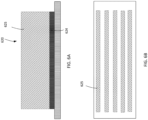
- the thermal dissipating feature 520 includes the metallic pin fin 525 disposed on the solder bump 524, as shown in the cross-sectional view of FIG. 5A .
- the thermal dissipating feature 520 may be configured as arrays or matrix that includes multiple thermal dissipating features 520 equally or non-equally spaced apart from each other.
- the thermal dissipating feature 520 may be configured to have a rectangular configuration as shown in the top view in FIG. 5B .
- the thermal dissipating feature 520 may have a dimension between about 20 ⁇ m and about 80 ⁇ m.
- the thermal dissipating feature 620 includes the metallic pin fin 625 disposed on the solder bump 624, as shown in the cross-sectional view of FIG. 6A .
- the thermal dissipating feature 620 may be configured as a longitudinal structure, such as in the form of bars as depicted in the top view of FIG. 6B , to facilitate dissipating thermal energy.
- FIG. 7 depicts a top view of a plurality of thermal dissipating features 720 disposed on a surface of an IC die.
- the numbers and densities of how the thermal dissipating feature 720 is disposed and placed on the IC die may be grouped and divided into different zones.
- three zones 751, 752, 753 are utilized so as to dispose different numbers of the thermal dissipating feature 720 in different zones 751, 752, 753.
- the numbers and the densities of the thermal dissipating features 720 may be disposed relatively higher in the edge zones 751, 753 relative to the center zone 752.
- thermal dissipation efficiencies may be obtained at different regions of the IC die so that a customized arrangement may be configured when the IC die has different device densities or device distributions across the width of the IC die.
- a relatively higher numbers or higher density of the thermal dissipating features 720 may be disposed on the center region of the IC die as well to facilitate efficient thermal energy in terms of the higher thermal energy as generated from the IC die. It is noted that the distribution, arrangement, numbers, and densities of the thermal dissipating features 720 disposed on the IC die may be divided into any numbers of the zones as necessary.
- FIG. 8 depicts a cross sectional view of a plurality of thermal dissipating feature 820 disposed on a surface of an IC die.
- each of the thermal dissipating feature 820 includes the metallic pin fin 825 disposed on the solder bump 824.
- the metallic pin fin 825 may be configured to have different heights to provide different thermal dissipating efficiency at different locations of the IC die, based on the design configurations and requirements from the IC die.
- the thermal dissipating feature 820 may have a first group of the metallic pin fin 825 having a first height 804 greater than a second group of the metallic pin fin 825 having a second height 806.
- the thermal dissipating feature 820 disposed on the IC die may have different aspect ratios, such as different ratios (H/D) of the height (H) 806, 804 to the diameter 802 (D), among the thermal dissipating feature 820.
- H/D ratios of the height (H) 806, 804 to the diameter 802 (D)
- FIG. 9 depicts a flow diagram for manufacturing an IC package including an IC die having a temperature control element utilized to control the temperature of the IC die in accordance with aspects of the disclosure.
- Such method may be performed using suitable manufacturing processes, including depositing, etching, lithography, polishing, soldering, or any suitable techniques. It should be understood that the operations involved in the following methods need not be performed in the precise order described. Rather, various operations may be handled in a different order or simultaneously, and operations may be added or omitted.
- an IC die such as the IC die 105 described above, may be disposed on a PCB, such as the PCB 106 described above.
- the IC die 105 may include device structures, transistors, or other electronic components formed on a device region of the IC die 105.
- a metallization layer such as the metallization layer 110, may be formed on the IC die.
- the metallization layer may be formed on a surface opposition to the surface where the device structures, transistors, or other electronic components are formed in the device region of the IC die.
- a plurality of thermal dissipating features may be disposed on the IC die.
- a manifold is placed on the PCB to encase the IC die therein while maintaining the plurality of thermal dissipating features located in a plenum defined in the manifold.
- a fluid may be supplied into the plenum of the manifold to efficiently control the temperature of the IC die through the plurality of thermal dissipating features.
- a temperature control element including the manifold and the plurality of thermal dissipating features is then implemented on the PCB encasing the IC die to form an IC package assembly with efficiency temperature dissipation control.
- the features described herein allow a temperature control element being formed as an integral part of an IC package assembly that may have high heat dissipation efficiency to an IC die during operation assembled in the package assembly.
- the temperature control element may assist temperature control of the IC die when in operation.
- the temperature control element may have a plurality of thermal dissipating features disposed on a first surface of the IC die encased under a manifold to efficiently control and dissipate the thermal energy from the IC die when in operation.
- a second surface opposite to the first surface of the IC die may include a plurality of devices, such as semiconductors transistors, devices, electrical components, circuits, or the like, that may generate thermal energy when in operation.
- the thermal dissipating features may be manufactured from a heat dissipation material to assist dissipating thermal energy generated by the plurality of devices in the IC die during operation when a fluid is supplied in the temperature control element.
- Different configurations of the thermal dissipating features may be utilized to accommodate different device layouts with different thermal energy generation across the substrate in the IC die.
- the temperature control element may provide an IC die with high efficiency of heat dissipation that is suitable for 3D IC package structures and requirements.
Applications Claiming Priority (2)
| Application Number | Priority Date | Filing Date | Title |
|---|---|---|---|
| US202163281287P | 2021-11-19 | 2021-11-19 | |
| US17/570,647 US11955406B2 (en) | 2021-11-19 | 2022-01-07 | Temperature control element utilized in device die packages |
Publications (1)
| Publication Number | Publication Date |
|---|---|
| EP4184563A1 true EP4184563A1 (de) | 2023-05-24 |
Family
ID=82786868
Family Applications (1)
| Application Number | Title | Priority Date | Filing Date |
|---|---|---|---|
| EP22188536.1A Pending EP4184563A1 (de) | 2021-11-19 | 2022-08-03 | Temperatursteuerungselement, das in bauteilverpackungen verwendet wird |
Country Status (2)
| Country | Link |
|---|---|
| US (1) | US11955406B2 (de) |
| EP (1) | EP4184563A1 (de) |
Families Citing this family (2)
| Publication number | Priority date | Publication date | Assignee | Title |
|---|---|---|---|---|
| US11434561B2 (en) * | 2020-03-27 | 2022-09-06 | STATS ChipPAC Pte. Ltd. | Cooling device and process for cooling double-sided SiP devices during sputtering |
| US11211364B1 (en) * | 2020-06-24 | 2021-12-28 | Micron Technology, Inc. | Semiconductor device assemblies and systems with improved thermal performance and methods for making the same |
Citations (4)
| Publication number | Priority date | Publication date | Assignee | Title |
|---|---|---|---|---|
| US20140126150A1 (en) * | 2012-11-08 | 2014-05-08 | David W. Song | Heat dissipation lid having direct liquid contact conduits |
| US20140307388A1 (en) * | 2013-04-11 | 2014-10-16 | Chia-Pin Chiu | Fluid-cooled heat dissipation device |
| US20190385925A1 (en) * | 2018-06-19 | 2019-12-19 | Intel Corporation | Cooling apparatuses for microelectronic assemblies |
| US20210098335A1 (en) * | 2019-09-29 | 2021-04-01 | Taiwan Semiconductor Manufacturing Co., Ltd. | Package structure and manufacturing method thereof |
Family Cites Families (14)
| Publication number | Priority date | Publication date | Assignee | Title |
|---|---|---|---|---|
| US7459782B1 (en) | 2005-10-05 | 2008-12-02 | Altera Corporation | Stiffener for flip chip BGA package |
| US7468886B2 (en) | 2007-03-05 | 2008-12-23 | International Business Machines Corporation | Method and structure to improve thermal dissipation from semiconductor devices |
| US7781883B2 (en) | 2008-08-19 | 2010-08-24 | International Business Machines Corporation | Electronic package with a thermal interposer and method of manufacturing the same |
| US20120006383A1 (en) | 2008-11-20 | 2012-01-12 | Donnelly Sean M | Heat exchanger apparatus and methods of manufacturing cross reference |
| CA2676495C (en) | 2009-08-24 | 2014-04-08 | Ibm Canada Limited - Ibm Canada Limitee | Mechanical barrier element for improved thermal reliability of electronic components |
| US8299608B2 (en) | 2010-07-08 | 2012-10-30 | International Business Machines Corporation | Enhanced thermal management of 3-D stacked die packaging |
| US9269646B2 (en) * | 2011-11-14 | 2016-02-23 | Micron Technology, Inc. | Semiconductor die assemblies with enhanced thermal management and semiconductor devices including same |
| US9070656B2 (en) | 2013-06-12 | 2015-06-30 | Micron Technology, Inc. | Underfill-accommodating heat spreaders and related semiconductor device assemblies and methods |
| US9735043B2 (en) | 2013-12-20 | 2017-08-15 | Taiwan Semiconductor Manufacturing Company, Ltd. | Semiconductor packaging structure and process |
| US10504816B2 (en) | 2017-09-06 | 2019-12-10 | Google Llc | Thermoelectric cooler (TEC) for spot cooling of 2.5D/3D IC packages |
| US10553522B1 (en) | 2018-08-13 | 2020-02-04 | International Business Machines Corporation | Semiconductor microcooler |
| US11239135B2 (en) * | 2019-07-18 | 2022-02-01 | Taiwan Semiconductor Manufacturing Company, Ltd. | Package structure and method of manufacturing the same |
| US11328975B2 (en) * | 2019-11-26 | 2022-05-10 | Taiwan Semiconductor Manufacturing Company, Ltd. | Semiconductor device |
| US11574853B2 (en) * | 2020-06-30 | 2023-02-07 | Taiwan Semiconductor Manufacturing Company, Ltd. | Semiconductor device |
-
2022
- 2022-01-07 US US17/570,647 patent/US11955406B2/en active Active
- 2022-08-03 EP EP22188536.1A patent/EP4184563A1/de active Pending
Patent Citations (4)
| Publication number | Priority date | Publication date | Assignee | Title |
|---|---|---|---|---|
| US20140126150A1 (en) * | 2012-11-08 | 2014-05-08 | David W. Song | Heat dissipation lid having direct liquid contact conduits |
| US20140307388A1 (en) * | 2013-04-11 | 2014-10-16 | Chia-Pin Chiu | Fluid-cooled heat dissipation device |
| US20190385925A1 (en) * | 2018-06-19 | 2019-12-19 | Intel Corporation | Cooling apparatuses for microelectronic assemblies |
| US20210098335A1 (en) * | 2019-09-29 | 2021-04-01 | Taiwan Semiconductor Manufacturing Co., Ltd. | Package structure and manufacturing method thereof |
Also Published As
| Publication number | Publication date |
|---|---|
| US11955406B2 (en) | 2024-04-09 |
| US20230163048A1 (en) | 2023-05-25 |
Similar Documents
| Publication | Publication Date | Title |
|---|---|---|
| EP4184563A1 (de) | Temperatursteuerungselement, das in bauteilverpackungen verwendet wird | |
| US8772927B2 (en) | Semiconductor package structures having liquid cooler integrated with first level chip package modules | |
| US8058724B2 (en) | Holistic thermal management system for a semiconductor chip | |
| US7611923B2 (en) | Method and apparatus for forming stacked die and substrate structures for increased packing density | |
| US7888786B2 (en) | Electronic module comprising memory and integrated circuit processor chips formed on a microchannel cooling device | |
| US9922902B2 (en) | Semiconductor device and semiconductor package | |
| US7335987B2 (en) | Semiconductor package and method for manufacturing the same | |
| US7589417B2 (en) | Microelectronic assembly having thermoelectric elements to cool a die and a method of making the same | |
| CN111211059B (zh) | 电子封装件及其制法与散热件 | |
| US9883612B2 (en) | Heat sink attachment on existing heat sinks | |
| CN213752684U (zh) | 具有竖直热管理的堆叠式硅封装组件 | |
| JP2006287080A (ja) | メモリモジュール | |
| CN114334949A (zh) | 具有热增强的三维ic封装 | |
| US11158562B2 (en) | Conformal integrated circuit (IC) device package lid | |
| CN102915984A (zh) | 半导体封装构造及其制造方法 | |
| EP4312249A1 (de) | Stiftrippenpositionierungsanordnung zur formung eines temperaturregelungselements zur verwendung in vorrichtungschipgehäusen | |
| US11973000B2 (en) | Heat dissipation plate and semiconductor device | |
| US20240055317A1 (en) | Compliant Pad Spacer for Three-Dimensional Integrated Circuit Package | |
| CN116613154B (zh) | 改善电源信号传输的2.5d封装结构及其制备方法 | |
| TW201343019A (zh) | 系統級封裝組件、印刷電路板組件及其製作方法 | |
| US20240063087A1 (en) | Thermal and mechanical enhanced thermal module structure on heterogeneous packages and methods for forming the same | |
| CN116705784A (zh) | 改善电源信号传输的2.5d封装结构及其制备方法 | |
| CN116207060A (zh) | 异质整合半导体封装结构 | |
| KR20240000507U (ko) | 적층형 집적 회로의 3차원 패키지에서 열 방출 및 전기적 견고성 개선 | |
| CN112542433A (zh) | 一种芯片封装结构及封装方法 |
Legal Events
| Date | Code | Title | Description |
|---|---|---|---|
| PUAI | Public reference made under article 153(3) epc to a published international application that has entered the european phase |
Free format text: ORIGINAL CODE: 0009012 |
|
| STAA | Information on the status of an ep patent application or granted ep patent |
Free format text: STATUS: THE APPLICATION HAS BEEN PUBLISHED |
|
| AK | Designated contracting states |
Kind code of ref document: A1 Designated state(s): AL AT BE BG CH CY CZ DE DK EE ES FI FR GB GR HR HU IE IS IT LI LT LU LV MC MK MT NL NO PL PT RO RS SE SI SK SM TR |
|
| STAA | Information on the status of an ep patent application or granted ep patent |
Free format text: STATUS: REQUEST FOR EXAMINATION WAS MADE |
|
| 17P | Request for examination filed |
Effective date: 20231122 |
|
| RBV | Designated contracting states (corrected) |
Designated state(s): AL AT BE BG CH CY CZ DE DK EE ES FI FR GB GR HR HU IE IS IT LI LT LU LV MC MK MT NL NO PL PT RO RS SE SI SK SM TR |