EP4184445A1 - Verfahren, vorrichtung, vorrichtung, system und speichermedium zum sammeln von räumlich-zeitlichen verhaltensweisen und zur erzeugung einer räumlich-zeitlichen verhaltensspur - Google Patents
Verfahren, vorrichtung, vorrichtung, system und speichermedium zum sammeln von räumlich-zeitlichen verhaltensweisen und zur erzeugung einer räumlich-zeitlichen verhaltensspur Download PDFInfo
- Publication number
- EP4184445A1 EP4184445A1 EP22822259.2A EP22822259A EP4184445A1 EP 4184445 A1 EP4184445 A1 EP 4184445A1 EP 22822259 A EP22822259 A EP 22822259A EP 4184445 A1 EP4184445 A1 EP 4184445A1
- Authority
- EP
- European Patent Office
- Prior art keywords
- sampling
- point
- displacement
- time
- points
- Prior art date
- Legal status (The legal status is an assumption and is not a legal conclusion. Google has not performed a legal analysis and makes no representation as to the accuracy of the status listed.)
- Granted
Links
Images

Classifications
-
- G—PHYSICS
- G06—COMPUTING OR CALCULATING; COUNTING
- G06T—IMAGE DATA PROCESSING OR GENERATION, IN GENERAL
- G06T19/00—Manipulating 3D models or images for computer graphics
- G06T19/003—Navigation within 3D models or images
-
- G—PHYSICS
- G06—COMPUTING OR CALCULATING; COUNTING
- G06T—IMAGE DATA PROCESSING OR GENERATION, IN GENERAL
- G06T11/00—2D [Two Dimensional] image generation
- G06T11/20—Drawing from basic elements, e.g. lines or circles
- G06T11/203—Drawing of straight lines or curves
-
- G—PHYSICS
- G06—COMPUTING OR CALCULATING; COUNTING
- G06F—ELECTRIC DIGITAL DATA PROCESSING
- G06F3/00—Input arrangements for transferring data to be processed into a form capable of being handled by the computer; Output arrangements for transferring data from processing unit to output unit, e.g. interface arrangements
- G06F3/01—Input arrangements or combined input and output arrangements for interaction between user and computer
- G06F3/011—Arrangements for interaction with the human body, e.g. for user immersion in virtual reality
- G06F3/012—Head tracking input arrangements
-
- G—PHYSICS
- G06—COMPUTING OR CALCULATING; COUNTING
- G06F—ELECTRIC DIGITAL DATA PROCESSING
- G06F3/00—Input arrangements for transferring data to be processed into a form capable of being handled by the computer; Output arrangements for transferring data from processing unit to output unit, e.g. interface arrangements
- G06F3/01—Input arrangements or combined input and output arrangements for interaction between user and computer
- G06F3/011—Arrangements for interaction with the human body, e.g. for user immersion in virtual reality
- G06F3/013—Eye tracking input arrangements
-
- G—PHYSICS
- G06—COMPUTING OR CALCULATING; COUNTING
- G06F—ELECTRIC DIGITAL DATA PROCESSING
- G06F3/00—Input arrangements for transferring data to be processed into a form capable of being handled by the computer; Output arrangements for transferring data from processing unit to output unit, e.g. interface arrangements
- G06F3/01—Input arrangements or combined input and output arrangements for interaction between user and computer
- G06F3/011—Arrangements for interaction with the human body, e.g. for user immersion in virtual reality
- G06F3/015—Input arrangements based on nervous system activity detection, e.g. brain waves [EEG] detection, electromyograms [EMG] detection, electrodermal response detection
-
- G—PHYSICS
- G06—COMPUTING OR CALCULATING; COUNTING
- G06Q—INFORMATION AND COMMUNICATION TECHNOLOGY [ICT] SPECIALLY ADAPTED FOR ADMINISTRATIVE, COMMERCIAL, FINANCIAL, MANAGERIAL OR SUPERVISORY PURPOSES; SYSTEMS OR METHODS SPECIALLY ADAPTED FOR ADMINISTRATIVE, COMMERCIAL, FINANCIAL, MANAGERIAL OR SUPERVISORY PURPOSES, NOT OTHERWISE PROVIDED FOR
- G06Q30/00—Commerce
- G06Q30/02—Marketing; Price estimation or determination; Fundraising
- G06Q30/0201—Market modelling; Market analysis; Collecting market data
-
- G—PHYSICS
- G06—COMPUTING OR CALCULATING; COUNTING
- G06Q—INFORMATION AND COMMUNICATION TECHNOLOGY [ICT] SPECIALLY ADAPTED FOR ADMINISTRATIVE, COMMERCIAL, FINANCIAL, MANAGERIAL OR SUPERVISORY PURPOSES; SYSTEMS OR METHODS SPECIALLY ADAPTED FOR ADMINISTRATIVE, COMMERCIAL, FINANCIAL, MANAGERIAL OR SUPERVISORY PURPOSES, NOT OTHERWISE PROVIDED FOR
- G06Q30/00—Commerce
- G06Q30/02—Marketing; Price estimation or determination; Fundraising
- G06Q30/0241—Advertisements
- G06Q30/0242—Determining effectiveness of advertisements
-
- G—PHYSICS
- G06—COMPUTING OR CALCULATING; COUNTING
- G06T—IMAGE DATA PROCESSING OR GENERATION, IN GENERAL
- G06T19/00—Manipulating 3D models or images for computer graphics
- G06T19/006—Mixed reality
-
- G—PHYSICS
- G06—COMPUTING OR CALCULATING; COUNTING
- G06F—ELECTRIC DIGITAL DATA PROCESSING
- G06F2203/00—Indexing scheme relating to G06F3/00 - G06F3/048
- G06F2203/01—Indexing scheme relating to G06F3/01
- G06F2203/011—Emotion or mood input determined on the basis of sensed human body parameters such as pulse, heart rate or beat, temperature of skin, facial expressions, iris, voice pitch, brain activity patterns
Definitions
- the present application relates to a field of spatiotemporal analysis, in particularly, relates to a method, apparatus, device, system and storage medium for collecting spatiotemporal behaviors and generating a spatiotemporal behavior track.
- a spatiotemporal behavior data of a subject in a virtual reality scene or a mixed reality scene is an important indicator to study whether the virtual reality scene or the mixed reality scene meets user expectation. Therefore, it has great significance for expanding functions of a virtual reality technology or a mixed reality technology that introducing the spatiotemporal analysis into the virtual reality technology or the mixed reality technology.
- In order to analyze a spatiotemporal behavior in the virtual reality it needs to be supported by a scientific evaluation indicator and an objective quantified data, and to obtain a moving track of the subject in the virtual reality scene or the mixed reality scene, so as to analyze a user satisfaction in the virtual reality scene or the mixed reality scene.
- a combination of the spatiotemporal analysis and the virtual reality scene or the mixed reality scene has not yet started.
- a current virtual reality or mixed reality spatial positioning technology such as laser positioning, infrared positioning, ultrasonic positioning and etc., can only calibrate a position of the subject and an interactive device in a virtual three-dimensional space in real time, and are limited to a construction and a display of the virtual reality scene or the mixed reality scene. Spatial information of the subject moving in the virtual reality scene or the mixed reality scene cannot be recorded comprehensively, completely and systematically.
- the present application provides a method, apparatus, device, system and storage medium for collecting spatiotemporal behaviors and generating a spatiotemporal behavior track.
- the present application provides the method for collecting and generating spatiotemporal behavior track, adopting the following technical solutions.
- the method for collecting and generating spatiotemporal behavior track includes:
- a middle time of the window time is the sampling time of the current sampling point, and the window time includes the sampling times corresponding to at least three sampling points.
- any one of the plurality of sampling points before the setting the window time based on the sampling time of the current sampling point, further includes: if the time interval between two adjacent sampling points in the first time series is within a preset interval, performing filling data in a gap between two adjacent sampling points.
- the filling data in a gap between two adjacent sampling points includes: filling the sampling points at a line connecting two adjacent sampling points according to a first interval; the first interval is calculated according to a distance between two adjacent sampling points and a number of invalid sampling points between two adjacent sampling points; the number of invalid sampling points is calculated according to the time interval between two adjacent sampling points and a sampling period.
- before the drawing the moving track map based on the second time series further includes:
- merging the two adjacent displacement points meeting an angular requirement can not only reduce a calculation volume of a subsequent data, but also ensure that the selected displacement points can accurately indicate an actual movement of the subject.
- before the drawing the moving track map based on the second time series further includes: taking any one of the displacement points as a current displacement point; if a duration time for which a subject is located at the current displacement point is less than a second time interval threshold, discarding the current displacement point; the duration time of the subject at the current displacement point is a time interval between the sampling time of the current displacement point and that of the next displacement point.
- the duration time of the subject at the current displacement point does not meet requirement, it is identified as a useless displacement point, and a data volume can be reduced to ensure calculation ability of a computer.
- the moving track map includes a displacement route map; the drawing the moving track map based on the plurality of displacement points includes:
- the moving track map includes a track thermogram; the drawing the moving track map based on the plurality of displacement points includes:
- the drawing the moving track map based on the plurality of displacement points further includes:
- the present application provides an apparatus for collecting spatiotemporal behaviors and generating a spatiotemporal behavior track, adopting the following technical solutions.
- the apparatus for collecting spatiotemporal behaviors and generating a spatiotemporal behavior track includes:
- the present application provides an electronic device, adopting the following technical solutions.
- the electronic device includes a memory and a processor; the memory can be configured for storing a computer program capable of being loaded by the processor and executing any one of the methods as described in the first aspect.
- the present application provides a system for collecting spatiotemporal behaviors and generating a spatiotemporal behavior track, adopting the following technical solutions.
- the system for collecting spatiotemporal behaviors and generating a spatiotemporal behavior track includes a reality display device and an electronic device as described in the third aspect;
- the present application provides a computer readable storage medium, adopting the following technical solutions.
- the computer readable storage medium is configured for storing a computer program capable of being loaded by a processor and executing any one of the methods as described in the first aspect.
- Subject an objective subject operating in a virtual reality scene or mixed reality scene.
- SOI Synignal Of Interest
- Virtual reality scene in a virtual reality system, a three-dimension scene or a two-dimension scene where the subject visits and interacts, such as three-dimension model scene, panorama picture, panorama video and etc.
- Mixed reality scene in a mixed reality system, a new visual environment generated by combining a reality scene and a virtual scene.
- the reality display device includes a VR (Virtual Reality) display device and a MR (Mediated Reality) display device; in the virtual reality scene, emitting a vertical ray from a center point of the VR display device to a ground of the virtual reality scene, and a point where the ray contacts a ground grid is the projection point of the VR display device; in the mixed reality scene, emitting the vertical ray from the center point of the MR display device to the ground of the mixed reality scene, and the point where the ray contacts the ground grid is the projection point of the MR display device.
- VR Virtual Reality
- MR Mediated Reality
- Displacement route map the displacement route map of the subject in the virtual reality scene or the mixed reality scene mapped according to the projection point of reality display device on the ground of the virtual reality scene or the mixed reality scene at different times and presented in a form of arrow.
- the virtual reality positioning technology or the mixed reality positioning technology mainly includes the following: Laser positioning: using a positioning light tower to emit lasers scanning in both horizontal and vertical directions to a positioning space; the positioned reality display device is provided with a plurality of laser induction receivers; calculating a coordinate of the subject by calculating an angle difference between two light beams reaching a positioning object.
- Infrared positioning shooting an indoor scene by using a camera, and tracking an active luminous marker point on the reality display device, and distinguishing different positioning points by different colors.
- an ultrasonic positioning system includes a transponder and main range finder, and the transponder is provided at a plurality of places indoors; the reality display device is provided with the main range finder, and measures distances between the reality display device and at least three transponders by emitting a radio wave and using a principle of sonar. Then, on a premise that a transponder coordinate is known, a position of the main range finder is calculated by using a triangle algorithm, that is, an indoor positioning of the subject is completed.
- the embodiments of the present application disclose a method for collecting spatiotemporal behaviors and generating a spatiotemporal behavior track, which is used in an electronic device.
- the electronic device includes but is not limited to: a mobile terminal such as a mobile phone, a laptop, a digital radio receiver, a PDA (personal digital assistant), a PAD (tablet personal computer), a PMP (portable multimedia player), a vehicular terminal (such as vehicular navigation terminal) and etc., and a fixed terminal such as a digital TV, a desktop computer and etc., and a server and etc.
- the method for collecting spatiotemporal behaviors and generating a spatiotemporal behavior track mainly includes the following steps.
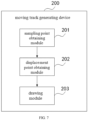
- Step S101 obtaining a first time series containing a plurality of sampling points, which are the projection points of the reality display device.
- the reality display device worn by the subject collects a position data of the subject by using a built-in position sensor thereof according to a preset sampling frequency, and sends the position data to the electronic device in real time by wireless or wired transmission. Then, the electronic device arranges the received position data in order of sampling time to obtain the first time series.
- the position sampling point corresponds to the position data one by one.
- the position data of the subject is the coordinate of the projection point of the reality display device worn by the subject.
- the sampling point is the projection point of the reality display device at the corresponding sampling time.
- a method for obtaining the coordinate can refer to the laser, infrared, ultrasonic and other positioning technologies mentioned above.
- the reality display device can be but is not limited to VR helmet, VR glasses and other virtual reality devices. For this, this embodiment is not specifically limited.
- Step S102 taking any one of the plurality of sampling points as a current sampling point; setting a window time based on the sampling time of the current sampling point, and finding a first sampling point and a last sampling point within the window time; taking a first position as a center of a circle, which is the center point of the reality display device corresponding to the current sampling point, and calculating an angular speed between the first sampling point and the last sampling point; if the angular speed is greater than a preset angular speed threshold, taking the current sampling point as a displacement point; processing the plurality of sampling points as described above to obtain a second time series containing a plurality of displacement points.
- sampling points in the first time series there are many sampling points in the first time series.
- the representative displacement point is the sampling point with large deviation amplitude of the subject. Because the sampling point with small relative displacement is not conducive to a subsequent drawing of a moving track, which not only affects a drawing efficiency, but also leads to a problem of unclear description of the moving track of subject in the virtual reality scene or the mixed reality scene. Thus, the sampling points with very small relative displacement can be ignored.
- the angular speed can be used in the embodiments of the present application to quickly determine the deviation degree of the subject, effectively avoid a height factor, and more accurately evaluate the deviation degree of the sampling point.
- a middle time of the window time is the sampling time of the current sampling point.
- the window time includes the sampling times corresponding to at least three sampling points, that is, the window time should not be less than two sampling periods (2T).
- the window time also needs to be set an upper limit value, which can be 4T, 6T or 8T, that is, the window time should not be greater than 4T, 6T or 8T.
- the first sampling point can be the sampling point corresponding to a minimum sampling time within the window time
- the last sampling point can be the sampling point corresponding to a maximum sampling time within the window time.
- the first sampling point can be the sampling point corresponding to the maximum sampling time within the window time
- the last sampling point can be the sampling point corresponding to the minimum sampling time within the window time.
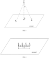
- FIG. 2 shows a time distribution of the sampling points with 3T as the window time.
- a sampling time t2 of the sampling point B is the middle time of the window time
- the sampling point A is the first sampling point within the window time
- the sampling point B is the last sampling point within the window time.
- a sampling time t1 of the sampling point A is earlier than a sampling time t3 of the sampling point C.
- a position of a first device corresponding to the current sampling point is the center point of the reality display device worn by the subject. Connecting the center point with the first sampling point and the last sampling point with straight lines respectively, and the two lines intersect to form a second included angle. Calculating the angular speed between the first sampling point and the last sampling point according to the second included angle and a time interval between the first sampling point and the last sampling point.
- FIG. 3 shows the spatial distribution of the three sampling points shown in FIG. 2 .
- the threshold of the preset angular speed can be set according to experience, for example 35°/s, and for this, the embodiment is not specifically limited.
- Step S103 drawing the moving track map based on the second time series.
- the position data of the subject may not be collected at some sampling times in step S101, thus there will be a plurality of invalid sampling points, and the plurality of sampling points obtained in step S 101 may be discontinuous.
- time interval between two adjacent sampling points in the first time series is within a preset interval, filling data in a gap between two adjacent sampling points.
- the two adjacent sampling points in the first time series mean that the sampling time of the two sampling points is adjacent.
- a lower limit value of the preset interval can be T, and an upper limit value thereof can be same as an interval parameter P of the reality display device.
- the interval parameter is obtained based on a displacement algorithm of the reality display device, that is, as long as the time interval between two adjacent sampling points in the time series is (T, P], the sampling point can be inserted between these two adjacent sampling points.
- sampling points at a line connecting two adjacent sampling points filling the sampling points at a line connecting two adjacent sampling points according to a first interval.
- the first interval is calculated according to a distance between two adjacent sampling points and a number of invalid sampling points between two adjacent sampling points.
- the number of invalid sampling points is calculated according to the time interval between two adjacent sampling points and the sampling period.
- d is a linear distance between the sampling points D and G
- n is the number of invalid sampling points between the sampling points D and G.
- the calculated first interval d successively inserting the sampling points E and F at the line DG. The distance between any two adjacent sampling points among the sampling points D, E, F and G after data filling is the first interval d.
- the plurality of sampling points after filling are arrayed according to the order of the sampling time by using the electronic device to obtain the first time series.
- time interval between two adjacent sampling points in the first time series is equal to T, it indicates there is no invalid sampling point between two adjacent sampling points. If the time interval between two adjacent sampling points in the first time series is greater than the upper limit P of the preset interval, it should be treated as a breakpoint without filling the sampling points.
- the embodiments of the present application uses an angle factor to determine the deviation degree of the subject, which can effectively avoid the height factor and can determine the deviation degree of the displacement point more accurately.
- the specific method is as follows.
- the second position is the center point of the reality display device corresponding to a displacement point with a later sampling time in the two adjacent displacement points. If yes, merging the two adjacent displacement points to a new displacement point.
- a sampling time t4 of the displacement point H is earlier than a sampling time t5 of the displacement point I.
- a center point I' of the reality display device where the subject is located at the displacement point I is the second position.
- An included angle between two lines respectively connecting the center point I' with the displacement points H and I is ⁇ . If ⁇ is less than the threshold of the first time interval, merging the displacement points H and I to the new displacement point.
- the specific method of merging can be as follows: connecting the displacement points H and I, and taking a middle point J as the new displacement point, then removing the displacement points H and I.
- a sampling time t6 of the displacement point J is a middle time of the sampling time t4 of the displacement point H and the sampling time t5 of the displacement point I.
- the threshold of the first time interval may be the same as the interval parameter P of the reality display device.
- the displacement points with short staying time can be discarded. Additionally, if the subject stays at one displacement point for a longer time, it indicates that the subject is more interested in this location. User interest and satisfaction are objectives of studying the moving track of the subject, thus the displacement points with very short staying time can be discarded.
- the specific method is as follows.
- any one of the plurality of displacement points taking any one of the displacement points as a current displacement point. If a duration time of the subject at the current displacement point is less than a second time interval threshold, discarding the current displacement point.
- the duration time of the subject at the current displacement point is a time interval between the sampling time of current displacement point and that of the next displacement point, which is in the second time series and adjacent to the current displacement point, and has a later sampling time.
- the threshold of the second time interval is set according to experience, sun as 60 ms, and for this, the embodiment is not specifically limited.
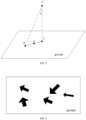
- the moving track map is used to describe the moving track of the subject in the virtual reality scene or the mixed reality scene, so as to analyze the spatiotemporal behavior of the subject in the virtual reality scene or the mixed reality scene, which can include but is not limited to the displacement route map and a track thermogram.
- the embodiment is not specifically limited.
- the display parameter is color, direction and area parameters of a figure.
- the direction of the arrow is used to indicate a moving trend of the subject, that is, always pointing from a previous displacement point to the current displacement point, and the sampling time of the previous displacement point is earlier than that of the current displacement point.
- the area of the arrow is positively correlated with a duration time of the subject at the current displacement point, that is, the longer the duration time of the current displacement point, the larger the area of the arrow.
- the area of the arrow will be expanded by 10% for each 1s increase of the duration time of the subject at the current displacement point.
- the color of the arrow can be preset, and the color of the arrow of different subjects can be different to distinguish the moving track of different subj ects.
- the moving tracks of the different subjects can be observed more intuitively, and the staying time of each subject in each area of the virtual reality scene or the mixed reality scene can be compared with each other, so as to subsequently analyzing the interest degree of the subjects.
- the track thermogram When drawing the track thermogram through the plurality of displacement points, first obtaining at least one SOI region in the virtual reality scene or the mixed reality scene, and counting a number of the displacement points in at least one SOI region. For any one of the SOI regions, determining a color intensity value based on the duration time of the subject at each displacement point and the number of the displacement points in a unit area, and drawing the track thermogram in the current SOI region based on the color intensity value.
- the duration time of the subject at each displacement point is the time interval between the sampling time of each displacement point and that of the next displacement point.
- the SOI regions can be sequenced based on the number of the displacement points in the region and the total duration time of the displacement points in the region. Specifically, setting a scoring standard for the number of the displacement points in the region and the total duration time of the displacement points in the region, and sequencing according to a score of each region, and the color intensity value of the SOI region with high scores is high.
- the color intensity value of the SOI region with more displacement points and/or longer duration time of the displacement point is higher than that of other SOI regions. According to the color intensity value, it can be quickly observed which one SOI region the subject is more interested in.
- the displacement route map and the track thermogram can be loaded in two-dimension or three-dimension map.
- an adjacent relationship described in the embodiments of the present application refers to the adjacent relationship in time concept, not in the space concept.
- an eye movement data and/or a physiological sign data of the subject at each displacement point also can be obtained, and the eye movement data and/or the physiological sign data of each displacement point are marked on the moving track map.
- the physiological sign data includes at least one of electroencephalogram (EEG), electromyography (EMG), heart rate, blood pressure, pulse, body temperature and respiratory rate.
- a standard deviation of EEG signal and respiratory rate can be used as an EEG change data and respiratory rate change data, after normalizing (the data can be mapped to a range of 0-1), obtaining the physiological sign change evaluation indicator.
- the higher a value of the physiological sign change evaluation indicator the higher the stimulation degree of the SOI region to the emotion of the subject, which is the higher the attraction of the SOI region to the subject.
- the access evaluation data, the gaze evaluation data and/or physiological sign change evaluation data of each SOI region are used as evaluation elements to associate with set evaluation indicators of each SOI region, so as to obtain the corresponding evaluation results.
- the embodiments of the present application further provide an apparatus for collecting spatiotemporal behaviors and generating a spatiotemporal behavior track, mainly including:
- the middle time of the window time is the sampling time of the current sampling point.
- the window time includes the sampling times corresponding to at least three sampling points.
- the apparatus further includes a filling module, configured for: for any one of the plurality of sampling points, before setting the window time based on the sampling time of the current sampling point, if the time interval between two adjacent sampling points in the first time series is within the preset interval, filling data in a gap between two adjacent sampling points.
- a filling module configured for: for any one of the plurality of sampling points, before setting the window time based on the sampling time of the current sampling point, if the time interval between two adjacent sampling points in the first time series is within the preset interval, filling data in a gap between two adjacent sampling points.
- the filling module is configured for filling the sampling points at the line connecting two adjacent sampling points according to the first interval.
- the first interval is calculated according to the distance between two adjacent sampling points and the number of invalid sampling points between two adjacent sampling points.
- the number of invalid sampling points is calculated according to the time interval between two adjacent sampling points and the sampling period.
- the apparatus further includes a merging module, configured for, before drawing the moving track map based on the plurality of displacement points, if the time interval between two adjacent displacement points in the second time series is less than the threshold of the first time interval, determining whether the included angle between the two connecting lines respectively connecting two adjacent displacement points with the second position is greater than the threshold of the preset angle.
- the second position is the center point of the reality display device corresponding to a displacement point with a later sampling time in the two adjacent displacement points; if yes, merging the two adjacent displacement points to the new displacement point.
- the apparatus further includes a discarding module, configured for, before drawing the moving track map based on the plurality of displacement points, for any one of the plurality of displacement points, if the duration time of the subject at the current displacement point is less than the threshold of the second time interval, discarding the current displacement point.
- the duration time of the subject at the current displacement point is the time interval between the sampling time of current displacement point and that of the next displacement point.
- the moving track map includes the displacement route map.
- the drawing module 203 is specifically configured for obtaining the display parameter of each displacement point, including color, direction and area.
- the direction is pointing from the previous displacement point to the current displacement point;
- the area is positively correlated with the duration time of subject at the current displacement point;
- the duration time of the subject at the current displacement point is the time interval between the sampling time of the current displacement point and that of the next displacement point.
- the moving track map includes the track thermogram.
- the drawing module 203 is specifically configured for obtaining at least one SOI region, and counting the number of the displacement points in at least one SOI region. For any one of the SOI regions, determining the color intensity value based on the duration time of each displacement point and the number of the displacement points in the unit area, and drawing the track thermogram in a current SOI region based on the color intensity value.
- the duration time of the subject at each displacement point is the time interval between the sampling time of each displacement point and that of the next displacement point.
- the apparatus further includes a marking module, configured for obtaining the eye movement data and/or the physiological sign data of the subject at each displacement point, and marking the eye movement data and/or the physiological sign data of each displacement point on the moving track map.
- the physiological sign data includes at least one of electroencephalogram (EEG), electromyography (EMG), heart rate, blood pressure, pulse, body temperature and respiratory rate.
- a unit in any one of the apparatus above can be one or more integrated circuits configured to implement the above method.
- ASICs application specific integrated circuits
- DSPs digital signal processors
- FPGAs field programmable gate arrays
- the unit in the apparatus can be implemented in a form of a scheduler of processing element, which can be a general purpose processor, such as a central processing unit (CPU) or other processors that can call a program.
- a scheduler of processing element can be a general purpose processor, such as a central processing unit (CPU) or other processors that can call a program.
- CPU central processing unit
- these units can be integrated together and implemented in a form of a system-on-a-chip (SOC).
- SOC system-on-a-chip
- the disclosed system, device and method can be realized in other ways.
- the apparatus embodiment described above only is exemplary.
- a division of the unit is only a logical function division, and there can be another division method in actual implementation, for example, a plurality of units or components can be combined or integrated into another system, or some features can be ignored or not implemented.
- a mutual coupling, direct coupling or communication connection shown or discussed can be an indirect coupling or communication connection by using some interfaces, devices or units, and can be electrical, mechanical or other forms.
- the units for separately describing the components may or may not be physically separated, and the components displayed as the unit may or may not be a physical unit, that is, they may be located at one place or distributed in a plurality of network units. Some or all of the units can be selected according to an actual need to achieve a purpose of the embodiments.
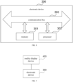
- the embodiments of the present application further provides the electronic device 300, which includes a memory 301, a processor 302 and a communication main line 303.
- the memory 301 can be configured for storing an instruction, the program, a code, a code set, or an instruction set, and can includes a storing program area and a storing data area.
- the storing program area can store the instruction for implementing an operation system, the instruction for realizing at least one function, the instruction for implementing the method for collecting spatiotemporal behaviors and generating a spatiotemporal behavior track according to the above embodiments, and etc.
- the storing data area can store the data involved in the method for collecting spatiotemporal behaviors and generating a spatiotemporal behavior track according to the above embodiments, and etc.
- the processor 302 can include one or more processing cores, and calls the data stored in the memory 301 and executing various functions and processing data of the present application by running or executing the instruction, the program, the code set or the instruction set stored in the memory 301.
- the processor 302 can be at least one of the application specific integrated circuit (ASIC), the digital signal processor (DSP), a digital signal processing device (DSPD), a programmable logic device (PLD), the field programmable gate array (FPGA), the central processing unit (CPU), a controller, a micro controller and a microprocessor.
- ASIC application specific integrated circuit
- DSP digital signal processor
- DSPD digital signal processing device
- PLD programmable logic device
- FPGA field programmable gate array
- CPU central processing unit
- controller a controller
- micro controller a micro controller and a microprocessor
- the communication main line 303 can further includes an access for transmitting information among the above components, and can be a peripheral component interconnect (PCI) main line, an extended industry standard architecture (EISA) main line and etc.
- PCI peripheral component interconnect
- EISA extended industry standard architecture
- the communication main line 303 can be divided into an address main line, a data main line, a control main line and etc. For a convenient representation, only one double arrow is used in FIG. 3 , but it does not mean that there is only one main line or one type of main line.
- the electronic device 300 includes but is not limited to the mobile phone, the laptop, the digital radio receiver, the PDA (personal digital assistant), the PAD (tablet personal computer), the PMP (portable multimedia player), the vehicular terminal (such as vehicular navigation terminal) and etc., and the fixed terminal such as the digital TV, the desktop computer and etc., and the server and etc.
- the electronic device 300 shown in FIG. 8 is only an example, and shall not limit the functions and a use scope of the embodiments in the present application.
- the embodiments in the present application also provides a system for collecting spatiotemporal behaviors and generating a spatiotemporal behavior track, including the reality display device 400 and the electronic device 300.
- the reality display device 400 is configured for collecting the coordinate of the projection point of the reality display device 400 based on the preset sampling frequency, and sending the position data to the electronic device 300.
- the electronic device 300 is configured for: obtaining the coordinate of the projection point of the reality display device 400, and generating the first time series containing a plurality of sampling points based on the coordinate of the projection point of the reality display device 400; for any one of the plurality of sampling points, setting the window time based on the sampling time of the current sampling point, and finding the first sampling point and the last sampling point within the window time; taking a first position as the center of the circle, which is the center point of the reality display device corresponding to the current sampling point, and calculating an angular speed between the first sampling point and the last sampling point; if the angular speed is greater than a threshold of the preset angular speed, taking the current sampling point as the displacement point; processing the plurality of sampling points as described above to obtain the second time series containing a plurality of displacement points; drawing and displaying the moving track map in the virtual reality scene or the mixed reality scene based on the plurality of displacement points.
- the technical solution of the present application essentially, or the part contributing to the existing technology or the part of the technical solution can be embodied in a form of software products.
- the computer software product is stored in a computer readable storage medium, including a number of instructions to make a computer device (may be a personal computer, the server, or the network device, etc.) to execute all or part of the steps of the method described in each embodiment of the present application.
- the computer readable storage medium mentioned above includes: u-disc, mobile hard disk, read-only memory (ROM), random access memory (RAM), magnetic disc or disc and other various medium which can store the program code.
Landscapes
- Engineering & Computer Science (AREA)
- Theoretical Computer Science (AREA)
- General Engineering & Computer Science (AREA)
- Physics & Mathematics (AREA)
- General Physics & Mathematics (AREA)
- Business, Economics & Management (AREA)
- Human Computer Interaction (AREA)
- Strategic Management (AREA)
- Finance (AREA)
- Development Economics (AREA)
- Accounting & Taxation (AREA)
- Entrepreneurship & Innovation (AREA)
- Software Systems (AREA)
- Game Theory and Decision Science (AREA)
- Economics (AREA)
- Computer Hardware Design (AREA)
- General Business, Economics & Management (AREA)
- Computer Graphics (AREA)
- Marketing (AREA)
- Neurology (AREA)
- Neurosurgery (AREA)
- Health & Medical Sciences (AREA)
- General Health & Medical Sciences (AREA)
- Dermatology (AREA)
- Biomedical Technology (AREA)
- Remote Sensing (AREA)
- Radar, Positioning & Navigation (AREA)
- Data Mining & Analysis (AREA)
- Processing Or Creating Images (AREA)
Applications Claiming Priority (2)
| Application Number | Priority Date | Filing Date | Title |
|---|---|---|---|
| CN202111172921.2A CN114022642B (zh) | 2021-10-08 | 2021-10-08 | 时空行为轨迹采集、生成方法、装置、设备、系统及存储介质 |
| PCT/CN2022/095697 WO2023056753A1 (zh) | 2021-10-08 | 2022-05-27 | 时空行为轨迹采集、生成方法、装置、设备、系统及存储介质 |
Publications (4)
| Publication Number | Publication Date |
|---|---|
| EP4184445A1 true EP4184445A1 (de) | 2023-05-24 |
| EP4184445A4 EP4184445A4 (de) | 2024-01-03 |
| EP4184445B1 EP4184445B1 (de) | 2025-07-02 |
| EP4184445C0 EP4184445C0 (de) | 2025-07-02 |
Family
ID=80055553
Family Applications (1)
| Application Number | Title | Priority Date | Filing Date |
|---|---|---|---|
| EP22822259.2A Active EP4184445B1 (de) | 2021-10-08 | 2022-05-27 | Verfahren, vorrichtung, system und speichermedium zum sammeln von räumlich-zeitlichen verhaltensweisen und zur erzeugung einer räumlich-zeitlichen verhaltensspur |
Country Status (6)
| Country | Link |
|---|---|
| US (1) | US12217337B2 (de) |
| EP (1) | EP4184445B1 (de) |
| CN (1) | CN114022642B (de) |
| ES (1) | ES3036383T3 (de) |
| WO (1) | WO2023056753A1 (de) |
| ZA (1) | ZA202402551B (de) |
Families Citing this family (4)
| Publication number | Priority date | Publication date | Assignee | Title |
|---|---|---|---|---|
| CN114022642B (zh) * | 2021-10-08 | 2022-07-19 | 北京津发科技股份有限公司 | 时空行为轨迹采集、生成方法、装置、设备、系统及存储介质 |
| CN116859246B (zh) * | 2023-07-25 | 2024-05-07 | 上海思格源智能科技有限公司 | 一种电池电芯自动识别方法及系统 |
| CN118587634B (zh) * | 2024-06-24 | 2024-12-27 | 北京航空航天大学 | 一种融合时空特征的监控视频行人轨迹重建方法及系统 |
| CN119577880B (zh) * | 2024-10-14 | 2025-08-08 | 北京市建筑设计研究院股份有限公司 | 利用vr采集步行轨迹对建筑空间设计进行量化分析的方法 |
Family Cites Families (19)
| Publication number | Priority date | Publication date | Assignee | Title |
|---|---|---|---|---|
| US10686972B2 (en) * | 2013-09-03 | 2020-06-16 | Tobii Ab | Gaze assisted field of view control |
| US9588593B2 (en) * | 2015-06-30 | 2017-03-07 | Ariadne's Thread (Usa), Inc. | Virtual reality system with control command gestures |
| US11188146B2 (en) * | 2015-10-17 | 2021-11-30 | Arivis Ag | Direct volume rendering in virtual and/or augmented reality |
| CN106123893A (zh) * | 2016-06-15 | 2016-11-16 | 北京奇虎科技有限公司 | 空间活动轨迹生成方法、装置 |
| CN107239144B (zh) * | 2017-06-09 | 2020-02-07 | 歌尔股份有限公司 | 一种设备的输入方法和装置 |
| CN108332771A (zh) * | 2018-01-12 | 2018-07-27 | 四川斐讯信息技术有限公司 | 一种在复杂环境中计算运动距离的方法及系统 |
| US10942564B2 (en) * | 2018-05-17 | 2021-03-09 | Sony Interactive Entertainment Inc. | Dynamic graphics rendering based on predicted saccade landing point |
| CN109271030B (zh) * | 2018-09-25 | 2020-12-22 | 华南理工大学 | 一种三维空间下注视点轨迹多维度比较方法 |
| IL282419B2 (en) * | 2018-10-23 | 2024-08-01 | Burke Neurological Inst | Systems and methods for evaluating contrast sensitivity and other visual metrics |
| US11256342B2 (en) * | 2019-04-03 | 2022-02-22 | Facebook Technologies, Llc | Multimodal kinematic template matching and regression modeling for ray pointing prediction in virtual reality |
| CN109961106B (zh) * | 2019-04-18 | 2022-03-18 | 北京百度网讯科技有限公司 | 轨迹分类模型的训练方法和装置、电子设备 |
| CN110941996A (zh) * | 2019-11-04 | 2020-03-31 | 深圳市唯特视科技有限公司 | 一种基于生成对抗网络的目标及轨迹增强现实方法和系统 |
| US11151788B2 (en) * | 2019-12-27 | 2021-10-19 | Woven Planet North America, Inc. | Systems and methods for presenting a reconstructed representation of a moving object detected in a scene |
| CN111309144B (zh) * | 2020-01-20 | 2022-02-01 | 北京津发科技股份有限公司 | 三维空间内注视行为的识别方法、装置及存储介质 |
| CN111265225B (zh) * | 2020-01-20 | 2022-04-12 | 北京津发科技股份有限公司 | 移动终端可用性的选择方法及装置 |
| CN111983210B (zh) * | 2020-06-29 | 2022-04-15 | 北京津发科技股份有限公司 | 基于时间同步的空间位置和多通道人机环境数据采集、时空行为分析方法和装置 |
| CN113064540B (zh) * | 2021-03-23 | 2022-11-01 | 网易(杭州)网络有限公司 | 基于游戏的绘制方法、绘制装置、电子设备及存储介质 |
| US12159352B2 (en) * | 2021-08-30 | 2024-12-03 | Bsset Llc | Extended reality movement platform |
| CN114022642B (zh) * | 2021-10-08 | 2022-07-19 | 北京津发科技股份有限公司 | 时空行为轨迹采集、生成方法、装置、设备、系统及存储介质 |
-
2021
- 2021-10-08 CN CN202111172921.2A patent/CN114022642B/zh active Active
-
2022
- 2022-05-27 WO PCT/CN2022/095697 patent/WO2023056753A1/zh not_active Ceased
- 2022-05-27 EP EP22822259.2A patent/EP4184445B1/de active Active
- 2022-05-27 ES ES22822259T patent/ES3036383T3/es active Active
- 2022-12-23 US US18/087,875 patent/US12217337B2/en active Active
-
2024
- 2024-04-02 ZA ZA2024/02551A patent/ZA202402551B/en unknown
Also Published As
| Publication number | Publication date |
|---|---|
| US12217337B2 (en) | 2025-02-04 |
| CN114022642A (zh) | 2022-02-08 |
| EP4184445B1 (de) | 2025-07-02 |
| EP4184445A4 (de) | 2024-01-03 |
| CN114022642B (zh) | 2022-07-19 |
| US20230126200A1 (en) | 2023-04-27 |
| ZA202402551B (en) | 2024-04-24 |
| WO2023056753A1 (zh) | 2023-04-13 |
| EP4184445C0 (de) | 2025-07-02 |
| ES3036383T3 (en) | 2025-09-18 |
Similar Documents
| Publication | Publication Date | Title |
|---|---|---|
| US12217337B2 (en) | Method, apparatus, device, system and storage medium for collecting spatiotemporal behaviors and generating a spatiotemporal behavior track | |
| US9483773B2 (en) | Point of view shopper camera system with orientation sensor | |
| US11620792B2 (en) | Fast hand meshing for dynamic occlusion | |
| CN110464365B (zh) | 一种关注度确定方法、装置、设备和存储介质 | |
| CN107820593A (zh) | 一种虚拟现实交互方法、装置及系统 | |
| CN111983210B (zh) | 基于时间同步的空间位置和多通道人机环境数据采集、时空行为分析方法和装置 | |
| JP2016122272A (ja) | 利用可能性算出装置、利用可能性算出方法及び利用可能性算出プログラム | |
| CN108594999B (zh) | 用于全景图像展示系统的控制方法和装置 | |
| WO2018171196A1 (zh) | 一种控制方法、终端及系统 | |
| CN104615978A (zh) | 视线方向跟踪方法及装置 | |
| Tian et al. | Behavior analysis of indoor escape route-finding based on head-mounted vr and eye tracking | |
| CN114860786A (zh) | 轨迹显示方法、电子设备、存储介质和程序产品 | |
| CN115089945A (zh) | 一种幼儿感觉统合训练方法、装置及系统 | |
| CN117826976A (zh) | 一种基于xr的多人协同方法及系统 | |
| Fedotov et al. | Towards estimating emotions and satisfaction level of tourist based on eye gaze and head movement | |
| RU2838823C2 (ru) | Способ, а также аппарат, устройство, система и носитель данных для получения и создания траектории пространственно-временного перемещения | |
| CN114332860A (zh) | 自然交互条件事件相关脑电标记方法、装置、介质、设备 | |
| KR20240015687A (ko) | 시각 능력을 특성화하기 위한 가상 현실 기법 | |
| Cruz et al. | Monitoring physiology and behavior using Android in phobias | |
| CN111784797A (zh) | 一种基于ar的机器人物联网交互方法、装置及介质 | |
| CN114519761B (zh) | 一种人脸纹理图的生成方法、装置、存储介质及设备 | |
| CN118400692B (zh) | 用于模拟训练的混合现实仿真定位方法、装置及设备 | |
| KR101568312B1 (ko) | 주사경로 추적을 이용한 공간탐색 특성정보 추출방법 | |
| CN110298702B (zh) | 信息展示方法、装置、智能机器人、存储介质及电子设备 | |
| CN106650581B (zh) | 一种人流量统计方法及装置 |
Legal Events
| Date | Code | Title | Description |
|---|---|---|---|
| STAA | Information on the status of an ep patent application or granted ep patent |
Free format text: STATUS: UNKNOWN |
|
| STAA | Information on the status of an ep patent application or granted ep patent |
Free format text: STATUS: THE INTERNATIONAL PUBLICATION HAS BEEN MADE |
|
| PUAI | Public reference made under article 153(3) epc to a published international application that has entered the european phase |
Free format text: ORIGINAL CODE: 0009012 |
|
| STAA | Information on the status of an ep patent application or granted ep patent |
Free format text: STATUS: REQUEST FOR EXAMINATION WAS MADE |
|
| 17P | Request for examination filed |
Effective date: 20221221 |
|
| AK | Designated contracting states |
Kind code of ref document: A1 Designated state(s): AL AT BE BG CH CY CZ DE DK EE ES FI FR GB GR HR HU IE IS IT LI LT LU LV MC MK MT NL NO PL PT RO RS SE SI SK SM TR |
|
| REG | Reference to a national code |
Ref country code: DE Ref legal event code: R079 Free format text: PREVIOUS MAIN CLASS: G06T0019000000 Ipc: G06F0003010000 Ref country code: DE Ref legal event code: R079 Ref document number: 602022017074 Country of ref document: DE Free format text: PREVIOUS MAIN CLASS: G06T0019000000 Ipc: G06F0003010000 |
|
| STAA | Information on the status of an ep patent application or granted ep patent |
Free format text: STATUS: EXAMINATION IS IN PROGRESS |
|
| A4 | Supplementary search report drawn up and despatched |
Effective date: 20231201 |
|
| RIC1 | Information provided on ipc code assigned before grant |
Ipc: G06Q 30/0242 20230101ALI20231127BHEP Ipc: G06Q 30/0201 20230101ALI20231127BHEP Ipc: G06F 3/01 20060101AFI20231127BHEP |
|
| 17Q | First examination report despatched |
Effective date: 20231213 |
|
| DAV | Request for validation of the european patent (deleted) | ||
| DAX | Request for extension of the european patent (deleted) | ||
| GRAP | Despatch of communication of intention to grant a patent |
Free format text: ORIGINAL CODE: EPIDOSNIGR1 |
|
| STAA | Information on the status of an ep patent application or granted ep patent |
Free format text: STATUS: GRANT OF PATENT IS INTENDED |
|
| RIC1 | Information provided on ipc code assigned before grant |
Ipc: G06Q 30/0242 20230101ALI20250120BHEP Ipc: G06Q 30/0201 20230101ALI20250120BHEP Ipc: G06F 3/01 20060101AFI20250120BHEP |
|
| INTG | Intention to grant announced |
Effective date: 20250130 |
|
| GRAS | Grant fee paid |
Free format text: ORIGINAL CODE: EPIDOSNIGR3 |
|
| GRAA | (expected) grant |
Free format text: ORIGINAL CODE: 0009210 |
|
| STAA | Information on the status of an ep patent application or granted ep patent |
Free format text: STATUS: THE PATENT HAS BEEN GRANTED |
|
| RAP1 | Party data changed (applicant data changed or rights of an application transferred) |
Owner name: BEIJING FILM ACADEMY Owner name: KINGFAR INTERNATIONAL INC. |
|
| RIN1 | Information on inventor provided before grant (corrected) |
Inventor name: YANG, ZICHU Inventor name: YANG, RAN Inventor name: ZHAO, QICHAO |
|
| RIN1 | Information on inventor provided before grant (corrected) |
Inventor name: YANG, RAN Inventor name: ZHAO, QICHAO Inventor name: YANG, ZICHU |
|
| AK | Designated contracting states |
Kind code of ref document: B1 Designated state(s): AL AT BE BG CH CY CZ DE DK EE ES FI FR GB GR HR HU IE IS IT LI LT LU LV MC MK MT NL NO PL PT RO RS SE SI SK SM TR |
|
| REG | Reference to a national code |
Ref country code: GB Ref legal event code: FG4D |
|
| REG | Reference to a national code |
Ref country code: CH Ref legal event code: EP |
|
| REG | Reference to a national code |
Ref country code: DE Ref legal event code: R096 Ref document number: 602022017074 Country of ref document: DE |
|
| REG | Reference to a national code |
Ref country code: IE Ref legal event code: FG4D |
|
| U01 | Request for unitary effect filed |
Effective date: 20250722 |
|
| U07 | Unitary effect registered |
Designated state(s): AT BE BG DE DK EE FI FR IT LT LU LV MT NL PT RO SE SI Effective date: 20250728 |
|
| REG | Reference to a national code |
Ref country code: ES Ref legal event code: FG2A Ref document number: 3036383 Country of ref document: ES Kind code of ref document: T3 Effective date: 20250918 |