EP4184445B1 - Verfahren, vorrichtung, system und speichermedium zum sammeln von räumlich-zeitlichen verhaltensweisen und zur erzeugung einer räumlich-zeitlichen verhaltensspur - Google Patents
Verfahren, vorrichtung, system und speichermedium zum sammeln von räumlich-zeitlichen verhaltensweisen und zur erzeugung einer räumlich-zeitlichen verhaltensspur Download PDFInfo
- Publication number
- EP4184445B1 EP4184445B1 EP22822259.2A EP22822259A EP4184445B1 EP 4184445 B1 EP4184445 B1 EP 4184445B1 EP 22822259 A EP22822259 A EP 22822259A EP 4184445 B1 EP4184445 B1 EP 4184445B1
- Authority
- EP
- European Patent Office
- Prior art keywords
- sampling
- point
- displacement
- points
- time
- Prior art date
- Legal status (The legal status is an assumption and is not a legal conclusion. Google has not performed a legal analysis and makes no representation as to the accuracy of the status listed.)
- Active
Links
Images

Classifications
-
- G—PHYSICS
- G06—COMPUTING OR CALCULATING; COUNTING
- G06T—IMAGE DATA PROCESSING OR GENERATION, IN GENERAL
- G06T19/00—Manipulating three-dimensional [3D] models or images for computer graphics
- G06T19/003—Navigation within 3D models or images
-
- G—PHYSICS
- G06—COMPUTING OR CALCULATING; COUNTING
- G06F—ELECTRIC DIGITAL DATA PROCESSING
- G06F3/00—Input arrangements for transferring data to be processed into a form capable of being handled by the computer; Output arrangements for transferring data from processing unit to output unit, e.g. interface arrangements
- G06F3/01—Input arrangements or combined input and output arrangements for interaction between user and computer
- G06F3/011—Arrangements for interaction with the human body, e.g. for user immersion in virtual reality
-
- G—PHYSICS
- G06—COMPUTING OR CALCULATING; COUNTING
- G06T—IMAGE DATA PROCESSING OR GENERATION, IN GENERAL
- G06T11/00—Two-dimensional [2D] image generation
- G06T11/20—Drawing from basic elements
- G06T11/23—Drawing from basic elements using straight lines or curves
-
- G—PHYSICS
- G06—COMPUTING OR CALCULATING; COUNTING
- G06F—ELECTRIC DIGITAL DATA PROCESSING
- G06F3/00—Input arrangements for transferring data to be processed into a form capable of being handled by the computer; Output arrangements for transferring data from processing unit to output unit, e.g. interface arrangements
- G06F3/01—Input arrangements or combined input and output arrangements for interaction between user and computer
- G06F3/011—Arrangements for interaction with the human body, e.g. for user immersion in virtual reality
- G06F3/012—Head tracking input arrangements
-
- G—PHYSICS
- G06—COMPUTING OR CALCULATING; COUNTING
- G06F—ELECTRIC DIGITAL DATA PROCESSING
- G06F3/00—Input arrangements for transferring data to be processed into a form capable of being handled by the computer; Output arrangements for transferring data from processing unit to output unit, e.g. interface arrangements
- G06F3/01—Input arrangements or combined input and output arrangements for interaction between user and computer
- G06F3/011—Arrangements for interaction with the human body, e.g. for user immersion in virtual reality
- G06F3/013—Eye tracking input arrangements
-
- G—PHYSICS
- G06—COMPUTING OR CALCULATING; COUNTING
- G06F—ELECTRIC DIGITAL DATA PROCESSING
- G06F3/00—Input arrangements for transferring data to be processed into a form capable of being handled by the computer; Output arrangements for transferring data from processing unit to output unit, e.g. interface arrangements
- G06F3/01—Input arrangements or combined input and output arrangements for interaction between user and computer
- G06F3/011—Arrangements for interaction with the human body, e.g. for user immersion in virtual reality
- G06F3/015—Input arrangements based on nervous system activity detection, e.g. brain waves [EEG] detection, electromyograms [EMG] detection, electrodermal response detection
-
- G—PHYSICS
- G06—COMPUTING OR CALCULATING; COUNTING
- G06Q—INFORMATION AND COMMUNICATION TECHNOLOGY [ICT] SPECIALLY ADAPTED FOR ADMINISTRATIVE, COMMERCIAL, FINANCIAL, MANAGERIAL OR SUPERVISORY PURPOSES; SYSTEMS OR METHODS SPECIALLY ADAPTED FOR ADMINISTRATIVE, COMMERCIAL, FINANCIAL, MANAGERIAL OR SUPERVISORY PURPOSES, NOT OTHERWISE PROVIDED FOR
- G06Q30/00—Commerce
- G06Q30/02—Marketing; Price estimation or determination; Fundraising
- G06Q30/0201—Market modelling; Market analysis; Collecting market data
-
- G—PHYSICS
- G06—COMPUTING OR CALCULATING; COUNTING
- G06Q—INFORMATION AND COMMUNICATION TECHNOLOGY [ICT] SPECIALLY ADAPTED FOR ADMINISTRATIVE, COMMERCIAL, FINANCIAL, MANAGERIAL OR SUPERVISORY PURPOSES; SYSTEMS OR METHODS SPECIALLY ADAPTED FOR ADMINISTRATIVE, COMMERCIAL, FINANCIAL, MANAGERIAL OR SUPERVISORY PURPOSES, NOT OTHERWISE PROVIDED FOR
- G06Q30/00—Commerce
- G06Q30/02—Marketing; Price estimation or determination; Fundraising
- G06Q30/0241—Advertisements
- G06Q30/0242—Determining effectiveness of advertisements
-
- G—PHYSICS
- G06—COMPUTING OR CALCULATING; COUNTING
- G06T—IMAGE DATA PROCESSING OR GENERATION, IN GENERAL
- G06T19/00—Manipulating three-dimensional [3D] models or images for computer graphics
- G06T19/006—Mixed reality
-
- G—PHYSICS
- G06—COMPUTING OR CALCULATING; COUNTING
- G06F—ELECTRIC DIGITAL DATA PROCESSING
- G06F2203/00—Indexing scheme relating to G06F3/00 - G06F3/048
- G06F2203/01—Indexing scheme relating to G06F3/01
- G06F2203/011—Emotion or mood input determined on the basis of sensed human body parameters such as pulse, heart rate or beat, temperature of skin, facial expressions, iris, voice pitch, brain activity patterns
Definitions
- the present application relates to a field of spatiotemporal analysis, in particularly, relates to a method, apparatus, device, system and storage medium for collecting spatiotemporal behaviors and generating a spatiotemporal behavior track.
- a spatiotemporal behavior data of a subject in a virtual reality scene or a mixed reality scene is an important indicator to study whether the virtual reality scene or the mixed reality scene meets user expectation. Therefore, it has great significance for expanding functions of a virtual reality technology or a mixed reality technology that introducing the spatiotemporal analysis into the virtual reality technology or the mixed reality technology.
- In order to analyze a spatiotemporal behavior in the virtual reality it needs to be supported by a scientific evaluation indicator and an objective quantified data, and to obtain a moving track of the subject in the virtual reality scene or the mixed reality scene, so as to analyze a user satisfaction in the virtual reality scene or the mixed reality scene.
- a combination of the spatiotemporal analysis and the virtual reality scene or the mixed reality scene has not yet started.
- a current virtual reality or mixed reality spatial positioning technology such as laser positioning, infrared positioning, ultrasonic positioning and etc., can only calibrate a position of the subject and an interactive device in a virtual three-dimensional space in real time, and are limited to a construction and a display of the virtual reality scene or the mixed reality scene. Spatial information of the subject moving in the virtual reality scene or the mixed reality scene cannot be recorded comprehensively, completely and systematically.
- the patent application CN111983210A discloses a spatial position and multi-channel man-machine environment data acquisition and space-time behavior analysis method and device based on time synchronization.
- the method comprises steps: based on a multidimensional data time synchronization technology, acquiring reaction data generated by an operator/participant in a to-be-analyzed three-dimensional space, wherein the reaction data comprises man-machine environment interaction data and spatial position data; by marking an interest area in a three-dimensional space, taking reaction data generated based on the interest area as an evaluation parameter, and analyzing the influence of the three-dimensional space on the behavior and psychological emotion of an operator/participant, so as to obtain the correlation between the behavior mode and psychological state change of the operator/participant and the design, layout, article and event in the three-dimensional space.
- the patent application CN111265225A discloses a mobile terminal availability selection method and a device thereof.
- the method comprises the following steps of: fixing an information content style of an interaction region, adjusting a style of a non-interaction region, and forming a first type of terminal style set; fixing the style of the non-interaction region, and adjusting the information content style of the interaction region to form a second type of terminal style set; obtaining eye movement data and heart rate variability data of a testee within specified interaction duration during interaction with each style in the first type of terminal style set and the second type of terminal style set, and calculating the number and/or occurrence frequency of saccadic points and an emotion change index; selecting a style of the non-interaction region of a terminal according to the number and/or occurrence frequency of each saccadic point corresponding to the first type of terminal style set; and selecting the information content style of the interaction region of the terminal according to each emotion change index corresponding to the second type of terminal style set.
- a middle time of the window time is the sampling time of the current sampling point, and the window time includes the sampling times corresponding to at least three sampling points.
- after the drawing the moving track map based on the plurality of displacement points further includes: obtaining an eye movement data and/or a physiological sign data of a subject at each displacement point, and marking the eye movement data and/or the physiological sign data of each displacement point on the moving track map;
- SOI Synignal Of Interest
- Virtual reality scene in a virtual reality system, a three-dimension scene or a two-dimension scene where the subject visits and interacts, such as three-dimension model scene, panorama picture, panorama video and etc.
- Mixed reality scene in a mixed reality system, a new visual environment generated by combining a reality scene and a virtual scene.
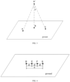
- the reality display device includes a VR (Virtual Reality) display device and a MR (Mediated Reality) display device; in the virtual reality scene, emitting a vertical ray from a center point of the VR display device to a ground of the virtual reality scene, and a point where the ray contacts a ground grid is the projection point of the VR display device; in the mixed reality scene, emitting the vertical ray from the center point of the MR display device to the ground of the mixed reality scene, and the point where the ray contacts the ground grid is the projection point of the MR display device.
- VR Virtual Reality
- MR Mediated Reality
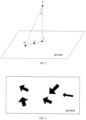
- Displacement route map the displacement route map of the subject in the virtual reality scene or the mixed reality scene mapped according to the projection point of reality display device on the ground of the virtual reality scene or the mixed reality scene at different times and presented in a form of arrow.
- the embodiments of the present application disclose a method for collecting spatiotemporal behaviors and generating a spatiotemporal behavior track, which is used in an electronic device.
- the electronic device includes but is not limited to: a mobile terminal such as a mobile phone, a laptop, a digital radio receiver, a PDA (personal digital assistant), a PAD (tablet personal computer), a PMP (portable multimedia player), a vehicular terminal (such as vehicular navigation terminal) and etc., and a fixed terminal such as a digital TV, a desktop computer and etc., and a server and etc.
- the method for collecting spatiotemporal behaviors and generating a spatiotemporal behavior track mainly includes the following steps.
- Step S101 obtaining a first time series containing a plurality of sampling points, which are the projection points of the reality display device.
- the position sampling point corresponds to the position data one by one.
- the position data of the subject is the coordinate of the projection point of the reality display device worn by the subject.
- the sampling point is the projection point of the reality display device at the corresponding sampling time.
- a method for obtaining the coordinate can refer to the laser, infrared, ultrasonic and other positioning technologies mentioned above.
- the reality display device can be but is not limited to VR helmet, VR glasses and other virtual reality devices. For this, this embodiment is not specifically limited.
- Step S102 taking any one of the plurality of sampling points as a current sampling point; setting a window time based on the sampling time of the current sampling point, and finding a first sampling point and a last sampling point within the window time; taking a first position as a center of a circle, which is the center point of the reality display device corresponding to the current sampling point, and calculating an angular speed between the first sampling point and the last sampling point; if the angular speed is greater than a preset angular speed threshold, taking the current sampling point as a displacement point; processing the plurality of sampling points as described above to obtain a second time series containing a plurality of displacement points.
- the angular speed is used in the embodiments of the present invention to quickly determine the deviation degree of the subject, effectively avoid a height factor, and more accurately evaluate the deviation degree of the sampling point.
- a middle time of the window time is the sampling time of the current sampling point.
- the window time includes the sampling times corresponding to at least three sampling points, that is, the window time should not be less than two sampling periods (2T).
- the window time also needs to be set an upper limit value, which can be 4T, 6T or 8T, that is, the window time should not be greater than 4T, 6T or 8T.
- the first sampling point can be the sampling point corresponding to a minimum sampling time within the window time
- the last sampling point can be the sampling point corresponding to a maximum sampling time within the window time.
- the first sampling point can be the sampling point corresponding to the maximum sampling time within the window time
- the last sampling point can be the sampling point corresponding to the minimum sampling time within the window time.
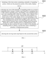
- FIG. 2 shows a time distribution of the sampling points with 3T as the window time.
- a sampling time t2 of the sampling point B is the middle time of the window time
- the sampling point A is the first sampling point within the window time
- the sampling point C is the last sampling point within the window time.
- a sampling time t1 of the sampling point A is earlier than a sampling time t3 of the sampling point C.
- a position of a first device corresponding to the current sampling point is the center point of the reality display device worn by the subject. Connecting the center point with the first sampling point and the last sampling point with straight lines respectively, and the two lines intersect to form a second included angle. Calculating the angular speed between the first sampling point and the last sampling point according to the second included angle and a time interval between the first sampling point and the last sampling point.
- FIG. 3 shows the spatial distribution of the three sampling points shown in FIG. 2 .
- the threshold of the preset angular speed can be set according to experience, for example 35°/s, and for this, the embodiment is not specifically limited.
- Step S103 drawing the moving track map based on the second time series.
- the position data of the subject may not be collected at some sampling times in step S101, thus there will be a plurality of invalid sampling points, and the plurality of sampling points obtained in step S101 may be discontinuous.
- time interval between two adjacent sampling points in the first time series is within a preset interval, filling data in a gap between two adjacent sampling points.
- sampling points at a line connecting two adjacent sampling points filling the sampling points at a line connecting two adjacent sampling points according to a first interval.
- the first interval is calculated according to a distance between two adjacent sampling points and a number of invalid sampling points between two adjacent sampling points.
- the number of invalid sampling points is calculated according to the time interval between two adjacent sampling points and the sampling period.
- d is a linear distance between the sampling points D and G
- n is the number of invalid sampling points between the sampling points D and G.
- the calculated first interval d successively inserting the sampling points E and F at the line DG. The distance between any two adjacent sampling points among the sampling points D, E, F and G after data filling is the first interval d.
- a unit in any one of the apparatus above can be one or more integrated circuits configured to implement the above method.
- ASICs application specific integrated circuits
- DSPs digital signal processors
- FPGAs field programmable gate arrays
- the unit in the apparatus can be implemented in a form of a scheduler of processing element, which can be a general purpose processor, such as a central processing unit (CPU) or other processors that can call a program.
- a scheduler of processing element can be a general purpose processor, such as a central processing unit (CPU) or other processors that can call a program.
- CPU central processing unit
- these units can be integrated together and implemented in a form of a system-on-a-chip (SOC).
- SOC system-on-a-chip
- the embodiments of the present application further provides the electronic device 300, which includes a memory 301, a processor 302 and a communication main line 303.
- the processor 302 can include one or more processing cores, and calls the data stored in the memory 301 and executing various functions and processing data of the present application by running or executing the instruction, the program, the code set or the instruction set stored in the memory 301.
- the processor 302 can be at least one of the application specific integrated circuit (ASIC), the digital signal processor (DSP), a digital signal processing device (DSPD), a programmable logic device (PLD), the field programmable gate array (FPGA), the central processing unit (CPU), a controller, a micro controller and a microprocessor.
- ASIC application specific integrated circuit
- DSP digital signal processor
- DSPD digital signal processing device
- PLD programmable logic device
- FPGA field programmable gate array
- CPU central processing unit
- controller a controller
- micro controller a micro controller and a microprocessor
- the communication main line 303 can further includes an access for transmitting information among the above components, and can be a peripheral component interconnect (PCI) main line, an extended industry standard architecture (EISA) main line and etc.
- PCI peripheral component interconnect
- EISA extended industry standard architecture
- the communication main line 303 can be divided into an address main line, a data main line, a control main line and etc. For a convenient representation, only one double arrow is used in FIG. 3 , but it does not mean that there is only one main line or one type of main line.
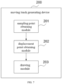
- the embodiments in the present application also provides a system for collecting spatiotemporal behaviors and generating a spatiotemporal behavior track, including the reality display device 400 and the electronic device 300.
- the reality display device 400 is configured for collecting the coordinate of the projection point of the reality display device 400 based on the preset sampling frequency, and sending the position data to the electronic device 300.
- the electronic device 300 is configured for: obtaining the coordinate of the projection point of the reality display device 400, and generating the first time series containing a plurality of sampling points based on the coordinate of the projection point of the reality display device 400; for any one of the plurality of sampling points, setting the window time based on the sampling time of the current sampling point, and finding the first sampling point and the last sampling point within the window time; taking a first position as the center of the circle, which is the center point of the reality display device corresponding to the current sampling point, and calculating an angular speed between the first sampling point and the last sampling point; if the angular speed is greater than a threshold of the preset angular speed, taking the current sampling point as the displacement point; processing the plurality of sampling points as described above to obtain the second time series containing a plurality of displacement points; drawing and displaying the moving track map in the virtual reality scene or the mixed reality scene based on the plurality of displacement points.
Landscapes
- Engineering & Computer Science (AREA)
- Theoretical Computer Science (AREA)
- General Engineering & Computer Science (AREA)
- General Physics & Mathematics (AREA)
- Physics & Mathematics (AREA)
- Business, Economics & Management (AREA)
- Human Computer Interaction (AREA)
- Strategic Management (AREA)
- Finance (AREA)
- Development Economics (AREA)
- Accounting & Taxation (AREA)
- Software Systems (AREA)
- Entrepreneurship & Innovation (AREA)
- Computer Graphics (AREA)
- Economics (AREA)
- Computer Hardware Design (AREA)
- General Business, Economics & Management (AREA)
- Marketing (AREA)
- Game Theory and Decision Science (AREA)
- Biomedical Technology (AREA)
- Health & Medical Sciences (AREA)
- Dermatology (AREA)
- General Health & Medical Sciences (AREA)
- Neurology (AREA)
- Neurosurgery (AREA)
- Radar, Positioning & Navigation (AREA)
- Remote Sensing (AREA)
- Data Mining & Analysis (AREA)
- Processing Or Creating Images (AREA)
Claims (11)
- Computer-implementiertes Verfahren zum Sammeln von raum-zeitlichen Verhaltensweisen und zum Erzeugen einer raum-zeitlichen Verhaltensroute eines Subjekts, das eine Virtual Reality-(VR)-Anzeigevorrichtung oder eine Mixed Reality-(MR)-Anzeigevorrichtung trägt, wobei das Verfahren umfasst:Erhalten einer ersten Zeitreihe, die eine Mehrzahl von Abtastpunkten (S101) enthält, wobei die Mehrzahl von Abtastpunkten vertikale Projektionen eines Mittelpunkts der VR-Anzeigevorrichtung oder der MR-Anzeigevorrichtung auf einen Boden einer Virtual-Reality-Szene bzw. einer Mixed-Reality-Szene sind;Auswählen eines beliebigen aus der Mehrzahl von Abtastpunkten als aktuellen Abtastpunkt (S102); Festlegen einer Fensterzeit auf der Grundlage einer Abtastzeit des aktuellen Abtastpunkts und Ermitteln eines ersten Abtastpunkts und eines letzten Abtastpunkts innerhalb der Fensterzeit, wobei eine mittlere Zeit der Fensterzeit die Abtastzeit des aktuellen Abtastpunkts ist und die Fensterzeit Abtastzeiten umfasst, die mindestens drei Abtastpunkten entsprechen; Nehmen einer ersten Position als Mittelpunkt eines Kreises, wobei die erste Position ein Mittelpunkt der VR-Anzeigevorrichtung oder der MR-Anzeigevorrichtung ist, der dem aktuellen Abtastpunkt entspricht; Bestimmen eines Winkels, der zwischen einer ersten Linie, die die erste Position mit dem ersten Abtastpunkt verbindet, und einer zweiten Linie, die die erste Position mit dem letzten Abtastpunkt verbindet, eingeschlossen ist; Berechnen einer Winkelgeschwindigkeit zwischen dem ersten Abtastpunkt und dem letzten Abtastpunkt gemäß dem Winkel zwischen der ersten Linie und der zweiten Linie und einem Zeitintervall zwischen dem ersten Abtastpunkt und dem letzten Abtastpunkt; und wenn die Winkelgeschwindigkeit größer ist als ein voreingestellter Schwellenwert für die Winkelgeschwindigkeit, wird der aktuelle Abtastpunkt als ein Verschiebungspunkt genommen;Durchführen des obigen Prozesses an jedem anderen der Mehrzahl von Abtastpunkten, um eine zweite Zeitreihe zu erhalten, die eine Mehrzahl von Verschiebungspunkten enthält; undZeichnen einer sich bewegenden Routenkarte auf der Grundlage der zweiten Zeitreihe (S103).
- Verfahren nach Anspruch 1, wobei das Verfahren vor dem Einstellen der Fensterzeit auf der Grundlage der Abtastzeit des aktuellen Abtastpunkts ferner umfasst:
wenn ein Zeitintervall zwischen zwei benachbarten Abtastpunkten in der ersten Zeitreihe innerhalb eines voreingestellten Intervalls liegt, werden Daten in eine Lücke zwischen den beiden benachbarten Abtastpunkten eingefügt. - Verfahren nach Anspruch 2, bei dem die Daten in einer Lücke zwischen den beiden benachbarten Abtastpunkten gesammelt werden:
Erfassen von Probenahmepunkten auf einer Linie, die die beiden benachbarten Probenahmepunkte in einem ersten Intervall verbindet; das erste Intervall wird auf der Grundlage eines Abstands zwischen den beiden benachbarten Probenahmepunkten und einer Anzahl fehlender Probenahmepunkte zwischen den beiden benachbarten Probenahmepunkten berechnet; die Anzahl fehlender Probenahmepunkte wird auf der Grundlage eines Zeitintervalls zwischen den beiden benachbarten Probenahmepunkten und einer Probenahmeperiode berechnet. - Verfahren nach Anspruch 1, wobei das Verfahren vor dem Zeichnen der Karte der sich bewegenden Route auf der Grundlage der zweiten Zeitreihe ferner umfasst:wenn ein Zeitintervall zwischen zwei benachbarten Verschiebungspunkten in der zweiten Zeitreihe kleiner als ein erster Zeitintervallschwellenwert ist, Bestimmen, ob ein eingeschlossener Winkel zwischen zwei Verbindungslinien, die jeweils die zwei benachbarten Verschiebungspunkte mit einer zweiten Position verbinden, größer als ein voreingestellter Winkelschwellenwert ist; wobei die zweite Position der Mittelpunkt der Realitätsanzeigevorrichtung ist, der einem Verschiebungspunkt mit einer späteren Abtastzeit in den zwei benachbarten Verschiebungspunkten entspricht;wenn der eingeschlossene Winkel zwischen zwei Verbindungslinien, die jeweils die beiden benachbarten Verschiebungspunkte mit der zweiten Position verbinden, größer ist als der voreingestellte Winkelschwellenwert, Zusammenführen der beiden benachbarten Verschiebungspunkte zu einem neuen Verschiebungspunkt.
- Verfahren nach Anspruch 1, wobei das Verfahren vor dem Zeichnen der Karte der sich bewegenden Route auf der Grundlage der zweiten Zeitreihe ferner umfasst:
Nehmen eines beliebigen der mehreren Verschiebungspunkte als einen aktuellen Verschiebungspunkt; wenn eine Zeitdauer, für die sich ein Subjekt an dem aktuellen Verschiebungspunkt befindet, kleiner als ein zweiter Zeitintervallschwellenwert ist, Verwerfen des aktuellen Verschiebungspunkts; wobei die Zeitdauer, für die sich das Subjekt an dem aktuellen Verschiebungspunkt befindet, ein Zeitintervall zwischen einer Abtastzeit des aktuellen Verschiebungspunkts und einer Abtastzeit des nächsten Verschiebungspunkts ist. - Verfahren nach Anspruch 1, wobei die sich bewegende Routenkarte eine Verschiebungsroutenkarte umfasst; wobei das Zeichnen der sich bewegenden Routenkarte basierend auf der Mehrzahl von Verschiebungspunkten umfasst:Erhalten eines Anzeigeparameters von jedem der mehreren Verschiebungspunkte, wobei der Anzeigeparameter Farbe, Richtung und Fläche umfasst, wobei die Richtung von einem vorhergehenden Verschiebungspunkt zu dem aktuellen Verschiebungspunkt zeigt, wobei die Fläche positiv mit einer Zeitdauer korreliert ist, für die sich ein Subjekt an dem aktuellen Verschiebungspunkt befindet; wobei die Zeitdauer, für die sich ein Subjekt an dem aktuellen Verschiebungspunkt befindet, ein Zeitintervall zwischen einer Abtastzeit des aktuellen Verschiebungspunkts und einer Abtastzeit des nächsten Verschiebungspunkts ist;Erzeugen der Verschiebungsroutenkarte auf der Grundlage der Anzeigeparameter jedes der mehreren Verschiebungspunkte.
- Verfahren nach Anspruch 1, wobei die sich bewegende Routenkarte ein Spurthermogramm umfasst; wobei das Zeichnen der sich bewegenden Routenkarte basierend auf der Mehrzahl von Verschiebungspunkten umfasst:Erhalten von mindestens einem Interessengebiet und Zählen einer Anzahl von Verschiebungspunkten in dem mindestens einen Interessengebiet;für ein beliebiges Interessengebiet, Bestimmen eines Farbintensitätswerts auf der Grundlage einer Zeitdauer, während der sich ein Subjekt an jedem der mehreren Verschiebungspunkte befindet, und der Anzahl der Verschiebungspunkte in einer Flächeneinheit, und Zeichnen eines Routenthermogramms in einem aktuellen Interessengebiet auf der Grundlage des Farbintensitätswerts; wobei die Zeitdauer des Subjekts an jedem Verschiebungspunkt ein Zeitintervall zwischen einer Abtastzeit jedes der mehreren Verschiebungspunkte und einer Abtastzeit des nächsten Verschiebungspunkts ist.
- Verfahren nach Anspruch 1, wobei das Verfahren nach dem Zeichnen der Karte der sich bewegenden Route auf der Grundlage der Mehrzahl von Verschiebungspunkten weiterhin umfasst:Erhalten von Augenbewegungsdaten und/oder physiologischen Zeichendaten eines Subjekts an jedem der mehreren Verschiebungspunkten, und Markieren der Augenbewegungsdaten und/oder der physiologischen Zeichendaten jedes der mehreren Verschiebungspunkte auf der sich bewegenden Routenkarte;wobei die physiologischen Zeichendaten mindestens eines der folgenden Elemente umfassen: Elektroenzephalogramm (EEG), Elektromyographie (EMG), Herzfrequenz, Blutdruck, Puls, Körpertemperatur und Atemfrequenz.
- Elektronische Vorrichtung (300), umfassend: einen Speicher (301) und einen Prozessor (302);
wobei der Speicher (301) ein Computerprogramm speichert, das so konfiguriert ist, dass es von dem Prozessor (302) geladen werden kann, um das Verfahren nach einem der Ansprüche 1 bis 8 durchzuführen. - System zum Sammeln von raum-zeitlichen Verhaltensweisen und zum Erzeugen einer raum-zeitlichen Verhaltensroute eines Subjekts, das eine Virtual Reality-(VR)-Anzeigevorrichtung oder eine Mixed Reality-(MR)-Anzeigevorrichtung trägt, wobei das System umfasst: eine Realitätsanzeigevorrichtung (400) und die elektronische Vorrichtung (300) nach Anspruch 9; wobeidie Realitätsanzeigevorrichtung (400) die VR-Anzeigevorrichtung oder die MR-Anzeigevorrichtung ist, die zum Sammeln einer Koordinate eines Projektionspunktes der VR-Anzeigevorrichtung oder der MR-Anzeigevorrichtung basierend auf einer voreingestellten Abtastfrequenz und zum Senden der Koordinate des Projektionspunktes der Realitätsanzeigevorrichtung (400) an die elektronische Vorrichtung (300) konfiguriert ist;wobei die elektronische Vorrichtung (300) dazu ausgelegt ist, die Koordinaten des Projektionspunkts der Realitätsanzeigevorrichtung (400) zu erhalten und eine erste Zeitreihe zu erzeugen, die mehrere Abtastpunkte auf der Grundlage der Koordinate des Projektionspunkts der Realitätsanzeigevorrichtung (400) enthält, wobei die mehreren Abtastpunkte vertikale Projektionen eines Mittelpunkts der VR-Anzeigevorrichtung oder der MR-Anzeigevorrichtung auf einen Boden einer Virtual-Reality-Szene bzw. einer Mixed-Reality-Szene sind.
- Computerlesbares Speichermedium mit einem darauf gespeicherten Computerprogramm, wobei das Computerprogramm so konfiguriert ist, dass es von einem Prozessor geladen werden kann und das Verfahren nach einem der Ansprüche 1-8 durchführt.
Applications Claiming Priority (2)
| Application Number | Priority Date | Filing Date | Title |
|---|---|---|---|
| CN202111172921.2A CN114022642B (zh) | 2021-10-08 | 2021-10-08 | 时空行为轨迹采集、生成方法、装置、设备、系统及存储介质 |
| PCT/CN2022/095697 WO2023056753A1 (zh) | 2021-10-08 | 2022-05-27 | 时空行为轨迹采集、生成方法、装置、设备、系统及存储介质 |
Publications (4)
| Publication Number | Publication Date |
|---|---|
| EP4184445A1 EP4184445A1 (de) | 2023-05-24 |
| EP4184445A4 EP4184445A4 (de) | 2024-01-03 |
| EP4184445B1 true EP4184445B1 (de) | 2025-07-02 |
| EP4184445C0 EP4184445C0 (de) | 2025-07-02 |
Family
ID=80055553
Family Applications (1)
| Application Number | Title | Priority Date | Filing Date |
|---|---|---|---|
| EP22822259.2A Active EP4184445B1 (de) | 2021-10-08 | 2022-05-27 | Verfahren, vorrichtung, system und speichermedium zum sammeln von räumlich-zeitlichen verhaltensweisen und zur erzeugung einer räumlich-zeitlichen verhaltensspur |
Country Status (6)
| Country | Link |
|---|---|
| US (1) | US12217337B2 (de) |
| EP (1) | EP4184445B1 (de) |
| CN (1) | CN114022642B (de) |
| ES (1) | ES3036383T3 (de) |
| WO (1) | WO2023056753A1 (de) |
| ZA (1) | ZA202402551B (de) |
Families Citing this family (4)
| Publication number | Priority date | Publication date | Assignee | Title |
|---|---|---|---|---|
| CN114022642B (zh) * | 2021-10-08 | 2022-07-19 | 北京津发科技股份有限公司 | 时空行为轨迹采集、生成方法、装置、设备、系统及存储介质 |
| CN116859246B (zh) * | 2023-07-25 | 2024-05-07 | 上海思格源智能科技有限公司 | 一种电池电芯自动识别方法及系统 |
| CN118587634B (zh) * | 2024-06-24 | 2024-12-27 | 北京航空航天大学 | 一种融合时空特征的监控视频行人轨迹重建方法及系统 |
| CN119577880B (zh) * | 2024-10-14 | 2025-08-08 | 北京市建筑设计研究院股份有限公司 | 利用vr采集步行轨迹对建筑空间设计进行量化分析的方法 |
Family Cites Families (19)
| Publication number | Priority date | Publication date | Assignee | Title |
|---|---|---|---|---|
| US10686972B2 (en) * | 2013-09-03 | 2020-06-16 | Tobii Ab | Gaze assisted field of view control |
| US9588593B2 (en) * | 2015-06-30 | 2017-03-07 | Ariadne's Thread (Usa), Inc. | Virtual reality system with control command gestures |
| US11188146B2 (en) * | 2015-10-17 | 2021-11-30 | Arivis Ag | Direct volume rendering in virtual and/or augmented reality |
| CN106123893A (zh) * | 2016-06-15 | 2016-11-16 | 北京奇虎科技有限公司 | 空间活动轨迹生成方法、装置 |
| CN107239144B (zh) * | 2017-06-09 | 2020-02-07 | 歌尔股份有限公司 | 一种设备的输入方法和装置 |
| CN108332771A (zh) * | 2018-01-12 | 2018-07-27 | 四川斐讯信息技术有限公司 | 一种在复杂环境中计算运动距离的方法及系统 |
| US10942564B2 (en) * | 2018-05-17 | 2021-03-09 | Sony Interactive Entertainment Inc. | Dynamic graphics rendering based on predicted saccade landing point |
| CN109271030B (zh) * | 2018-09-25 | 2020-12-22 | 华南理工大学 | 一种三维空间下注视点轨迹多维度比较方法 |
| US11583178B2 (en) * | 2018-10-23 | 2023-02-21 | Burke Neurological Institute | Systems and methods for evaluating contrast sensitivity and other visual metrics |
| US11256342B2 (en) * | 2019-04-03 | 2022-02-22 | Facebook Technologies, Llc | Multimodal kinematic template matching and regression modeling for ray pointing prediction in virtual reality |
| CN109961106B (zh) * | 2019-04-18 | 2022-03-18 | 北京百度网讯科技有限公司 | 轨迹分类模型的训练方法和装置、电子设备 |
| CN110941996A (zh) * | 2019-11-04 | 2020-03-31 | 深圳市唯特视科技有限公司 | 一种基于生成对抗网络的目标及轨迹增强现实方法和系统 |
| US11151788B2 (en) * | 2019-12-27 | 2021-10-19 | Woven Planet North America, Inc. | Systems and methods for presenting a reconstructed representation of a moving object detected in a scene |
| CN111309144B (zh) * | 2020-01-20 | 2022-02-01 | 北京津发科技股份有限公司 | 三维空间内注视行为的识别方法、装置及存储介质 |
| CN111265225B (zh) * | 2020-01-20 | 2022-04-12 | 北京津发科技股份有限公司 | 移动终端可用性的选择方法及装置 |
| CN111983210B (zh) * | 2020-06-29 | 2022-04-15 | 北京津发科技股份有限公司 | 基于时间同步的空间位置和多通道人机环境数据采集、时空行为分析方法和装置 |
| CN113064540B (zh) * | 2021-03-23 | 2022-11-01 | 网易(杭州)网络有限公司 | 基于游戏的绘制方法、绘制装置、电子设备及存储介质 |
| US12159352B2 (en) * | 2021-08-30 | 2024-12-03 | Bsset Llc | Extended reality movement platform |
| CN114022642B (zh) * | 2021-10-08 | 2022-07-19 | 北京津发科技股份有限公司 | 时空行为轨迹采集、生成方法、装置、设备、系统及存储介质 |
-
2021
- 2021-10-08 CN CN202111172921.2A patent/CN114022642B/zh active Active
-
2022
- 2022-05-27 WO PCT/CN2022/095697 patent/WO2023056753A1/zh not_active Ceased
- 2022-05-27 EP EP22822259.2A patent/EP4184445B1/de active Active
- 2022-05-27 ES ES22822259T patent/ES3036383T3/es active Active
- 2022-12-23 US US18/087,875 patent/US12217337B2/en active Active
-
2024
- 2024-04-02 ZA ZA2024/02551A patent/ZA202402551B/en unknown
Also Published As
| Publication number | Publication date |
|---|---|
| EP4184445A1 (de) | 2023-05-24 |
| WO2023056753A1 (zh) | 2023-04-13 |
| US20230126200A1 (en) | 2023-04-27 |
| CN114022642A (zh) | 2022-02-08 |
| EP4184445C0 (de) | 2025-07-02 |
| US12217337B2 (en) | 2025-02-04 |
| ES3036383T3 (en) | 2025-09-18 |
| ZA202402551B (en) | 2024-04-24 |
| EP4184445A4 (de) | 2024-01-03 |
| CN114022642B (zh) | 2022-07-19 |
Similar Documents
| Publication | Publication Date | Title |
|---|---|---|
| EP4184445B1 (de) | Verfahren, vorrichtung, system und speichermedium zum sammeln von räumlich-zeitlichen verhaltensweisen und zur erzeugung einer räumlich-zeitlichen verhaltensspur | |
| JP6447108B2 (ja) | 利用可能性算出装置、利用可能性算出方法及び利用可能性算出プログラム | |
| US9483773B2 (en) | Point of view shopper camera system with orientation sensor | |
| US11620792B2 (en) | Fast hand meshing for dynamic occlusion | |
| US20170115742A1 (en) | Wearable augmented reality eyeglass communication device including mobile phone and mobile computing via virtual touch screen gesture control and neuron command | |
| CN111983210B (zh) | 基于时间同步的空间位置和多通道人机环境数据采集、时空行为分析方法和装置 | |
| JP2022519149A (ja) | 展示エリア状態認識方法、装置、電子デバイス、及び記録媒体 | |
| WO2018127782A1 (en) | Wearable augmented reality eyeglass communication device including mobile phone and mobile computing via virtual touch screen gesture control and neuron command | |
| WO2018171196A1 (zh) | 一种控制方法、终端及系统 | |
| CN110464365A (zh) | 一种关注度确定方法、装置、设备和存储介质 | |
| US11062140B2 (en) | Display method, electronic device and storage medium having the same | |
| CN115471903B (zh) | 认知评估系统 | |
| CN117808348A (zh) | 基于虚拟现实的显示屏人机交互界面设计测评方法和系统 | |
| KR20260035858A (ko) | 멀티 센싱 정보를 이용한 실감형 콘텐츠 제어 서버 및 동작 방법 | |
| CN117826976A (zh) | 一种基于xr的多人协同方法及系统 | |
| KR20240015687A (ko) | 시각 능력을 특성화하기 위한 가상 현실 기법 | |
| Othman et al. | CrowdEyes: Crowdsourcing for robust real-world mobile eye tracking | |
| Fedotov et al. | Towards estimating emotions and satisfaction level of tourist based on eye gaze and head movement | |
| RU2838823C2 (ru) | Способ, а также аппарат, устройство, система и носитель данных для получения и создания траектории пространственно-временного перемещения | |
| CN111290579B (zh) | 虚拟内容的控制方法、装置、电子设备及计算机可读介质 | |
| Cruz et al. | Monitoring physiology and behavior using Android in phobias | |
| CN115168628A (zh) | 信息推荐方法、装置、电子设备及存储介质 | |
| Bosta et al. | A Multimodal Approach to User Experience Evaluation: Integration of Physiological, Behavioral, Contextual and Self-Report data with UserSence | |
| CN114863093B (zh) | 基于眼动技术的神经网络训练方法及建筑设计方法和系统 | |
| CN115188494A (zh) | 运动监测方法、装置、可穿戴设备、系统及存储介质 |
Legal Events
| Date | Code | Title | Description |
|---|---|---|---|
| STAA | Information on the status of an ep patent application or granted ep patent |
Free format text: STATUS: UNKNOWN |
|
| STAA | Information on the status of an ep patent application or granted ep patent |
Free format text: STATUS: THE INTERNATIONAL PUBLICATION HAS BEEN MADE |
|
| PUAI | Public reference made under article 153(3) epc to a published international application that has entered the european phase |
Free format text: ORIGINAL CODE: 0009012 |
|
| STAA | Information on the status of an ep patent application or granted ep patent |
Free format text: STATUS: REQUEST FOR EXAMINATION WAS MADE |
|
| 17P | Request for examination filed |
Effective date: 20221221 |
|
| AK | Designated contracting states |
Kind code of ref document: A1 Designated state(s): AL AT BE BG CH CY CZ DE DK EE ES FI FR GB GR HR HU IE IS IT LI LT LU LV MC MK MT NL NO PL PT RO RS SE SI SK SM TR |
|
| REG | Reference to a national code |
Ref country code: DE Free format text: PREVIOUS MAIN CLASS: G06T0019000000 Ref legal event code: R079 Ref document number: 602022017074 Country of ref document: DE Ipc: G06F0003010000 |
|
| STAA | Information on the status of an ep patent application or granted ep patent |
Free format text: STATUS: EXAMINATION IS IN PROGRESS |
|
| A4 | Supplementary search report drawn up and despatched |
Effective date: 20231201 |
|
| RIC1 | Information provided on ipc code assigned before grant |
Ipc: G06Q 30/0242 20230101ALI20231127BHEP Ipc: G06Q 30/0201 20230101ALI20231127BHEP Ipc: G06F 3/01 20060101AFI20231127BHEP |
|
| 17Q | First examination report despatched |
Effective date: 20231213 |
|
| DAV | Request for validation of the european patent (deleted) | ||
| DAX | Request for extension of the european patent (deleted) | ||
| GRAP | Despatch of communication of intention to grant a patent |
Free format text: ORIGINAL CODE: EPIDOSNIGR1 |
|
| STAA | Information on the status of an ep patent application or granted ep patent |
Free format text: STATUS: GRANT OF PATENT IS INTENDED |
|
| RIC1 | Information provided on ipc code assigned before grant |
Ipc: G06Q 30/0242 20230101ALI20250120BHEP Ipc: G06Q 30/0201 20230101ALI20250120BHEP Ipc: G06F 3/01 20060101AFI20250120BHEP |
|
| INTG | Intention to grant announced |
Effective date: 20250130 |
|
| GRAS | Grant fee paid |
Free format text: ORIGINAL CODE: EPIDOSNIGR3 |
|
| GRAA | (expected) grant |
Free format text: ORIGINAL CODE: 0009210 |
|
| STAA | Information on the status of an ep patent application or granted ep patent |
Free format text: STATUS: THE PATENT HAS BEEN GRANTED |
|
| RAP1 | Party data changed (applicant data changed or rights of an application transferred) |
Owner name: BEIJING FILM ACADEMY Owner name: KINGFAR INTERNATIONAL INC. |
|
| RIN1 | Information on inventor provided before grant (corrected) |
Inventor name: YANG, ZICHU Inventor name: YANG, RAN Inventor name: ZHAO, QICHAO |
|
| RIN1 | Information on inventor provided before grant (corrected) |
Inventor name: YANG, RAN Inventor name: ZHAO, QICHAO Inventor name: YANG, ZICHU |
|
| AK | Designated contracting states |
Kind code of ref document: B1 Designated state(s): AL AT BE BG CH CY CZ DE DK EE ES FI FR GB GR HR HU IE IS IT LI LT LU LV MC MK MT NL NO PL PT RO RS SE SI SK SM TR |
|
| REG | Reference to a national code |
Ref country code: GB Ref legal event code: FG4D |
|
| REG | Reference to a national code |
Ref country code: CH Ref legal event code: EP |
|
| REG | Reference to a national code |
Ref country code: DE Ref legal event code: R096 Ref document number: 602022017074 Country of ref document: DE |
|
| REG | Reference to a national code |
Ref country code: IE Ref legal event code: FG4D |
|
| U01 | Request for unitary effect filed |
Effective date: 20250722 |
|
| U07 | Unitary effect registered |
Designated state(s): AT BE BG DE DK EE FI FR IT LT LU LV MT NL PT RO SE SI Effective date: 20250728 |
|
| REG | Reference to a national code |
Ref country code: ES Ref legal event code: FG2A Ref document number: 3036383 Country of ref document: ES Kind code of ref document: T3 Effective date: 20250918 |
|
| PG25 | Lapsed in a contracting state [announced via postgrant information from national office to epo] |
Ref country code: IS Free format text: LAPSE BECAUSE OF FAILURE TO SUBMIT A TRANSLATION OF THE DESCRIPTION OR TO PAY THE FEE WITHIN THE PRESCRIBED TIME-LIMIT Effective date: 20251102 |
|
| PG25 | Lapsed in a contracting state [announced via postgrant information from national office to epo] |
Ref country code: NO Free format text: LAPSE BECAUSE OF FAILURE TO SUBMIT A TRANSLATION OF THE DESCRIPTION OR TO PAY THE FEE WITHIN THE PRESCRIBED TIME-LIMIT Effective date: 20251002 |
|
| PG25 | Lapsed in a contracting state [announced via postgrant information from national office to epo] |
Ref country code: HR Free format text: LAPSE BECAUSE OF FAILURE TO SUBMIT A TRANSLATION OF THE DESCRIPTION OR TO PAY THE FEE WITHIN THE PRESCRIBED TIME-LIMIT Effective date: 20250702 |
|
| PG25 | Lapsed in a contracting state [announced via postgrant information from national office to epo] |
Ref country code: GR Free format text: LAPSE BECAUSE OF FAILURE TO SUBMIT A TRANSLATION OF THE DESCRIPTION OR TO PAY THE FEE WITHIN THE PRESCRIBED TIME-LIMIT Effective date: 20251003 |
|
| PG25 | Lapsed in a contracting state [announced via postgrant information from national office to epo] |
Ref country code: CZ Free format text: LAPSE BECAUSE OF FAILURE TO SUBMIT A TRANSLATION OF THE DESCRIPTION OR TO PAY THE FEE WITHIN THE PRESCRIBED TIME-LIMIT Effective date: 20250702 |
|
| PG25 | Lapsed in a contracting state [announced via postgrant information from national office to epo] |
Ref country code: PL Free format text: LAPSE BECAUSE OF FAILURE TO SUBMIT A TRANSLATION OF THE DESCRIPTION OR TO PAY THE FEE WITHIN THE PRESCRIBED TIME-LIMIT Effective date: 20250702 |
|
| PG25 | Lapsed in a contracting state [announced via postgrant information from national office to epo] |
Ref country code: RS Free format text: LAPSE BECAUSE OF FAILURE TO SUBMIT A TRANSLATION OF THE DESCRIPTION OR TO PAY THE FEE WITHIN THE PRESCRIBED TIME-LIMIT Effective date: 20251002 |
|
| PG25 | Lapsed in a contracting state [announced via postgrant information from national office to epo] |
Ref country code: SM Free format text: LAPSE BECAUSE OF FAILURE TO SUBMIT A TRANSLATION OF THE DESCRIPTION OR TO PAY THE FEE WITHIN THE PRESCRIBED TIME-LIMIT Effective date: 20250702 |