EP4184030A1 - Kupplung mit einem antrieb, einem abtrieb und einer sperrklinke - Google Patents
Kupplung mit einem antrieb, einem abtrieb und einer sperrklinke Download PDFInfo
- Publication number
- EP4184030A1 EP4184030A1 EP22203941.4A EP22203941A EP4184030A1 EP 4184030 A1 EP4184030 A1 EP 4184030A1 EP 22203941 A EP22203941 A EP 22203941A EP 4184030 A1 EP4184030 A1 EP 4184030A1
- Authority
- EP
- European Patent Office
- Prior art keywords
- pawl
- drive
- output
- furniture
- rotation
- Prior art date
- Legal status (The legal status is an assumption and is not a legal conclusion. Google has not performed a legal analysis and makes no representation as to the accuracy of the status listed.)
- Granted
Links
Images


Classifications
-
- F—MECHANICAL ENGINEERING; LIGHTING; HEATING; WEAPONS; BLASTING
- F16—ENGINEERING ELEMENTS AND UNITS; GENERAL MEASURES FOR PRODUCING AND MAINTAINING EFFECTIVE FUNCTIONING OF MACHINES OR INSTALLATIONS; THERMAL INSULATION IN GENERAL
- F16D—COUPLINGS FOR TRANSMITTING ROTATION; CLUTCHES; BRAKES
- F16D41/00—Freewheels or freewheel clutches
- F16D41/12—Freewheels or freewheel clutches with hinged pawl co-operating with teeth, cogs, or the like
- F16D41/16—Freewheels or freewheel clutches with hinged pawl co-operating with teeth, cogs, or the like the action being reversible
-
- E—FIXED CONSTRUCTIONS
- E05—LOCKS; KEYS; WINDOW OR DOOR FITTINGS; SAFES
- E05D—HINGES OR SUSPENSION DEVICES FOR DOORS, WINDOWS OR WINGS
- E05D15/00—Suspension arrangements for wings
- E05D15/40—Suspension arrangements for wings supported on arms movable in vertical planes
-
- E—FIXED CONSTRUCTIONS
- E05—LOCKS; KEYS; WINDOW OR DOOR FITTINGS; SAFES
- E05F—DEVICES FOR MOVING WINGS INTO OPEN OR CLOSED POSITION; CHECKS FOR WINGS; WING FITTINGS NOT OTHERWISE PROVIDED FOR, CONCERNED WITH THE FUNCTIONING OF THE WING
- E05F15/00—Power-operated mechanisms for wings
- E05F15/60—Power-operated mechanisms for wings using electrical actuators
- E05F15/603—Power-operated mechanisms for wings using electrical actuators using rotary electromotors
- E05F15/611—Power-operated mechanisms for wings using electrical actuators using rotary electromotors for swinging wings
- E05F15/63—Power-operated mechanisms for wings using electrical actuators using rotary electromotors for swinging wings operated by swinging arms
-
- E—FIXED CONSTRUCTIONS
- E05—LOCKS; KEYS; WINDOW OR DOOR FITTINGS; SAFES
- E05D—HINGES OR SUSPENSION DEVICES FOR DOORS, WINDOWS OR WINGS
- E05D3/00—Hinges with pins
- E05D3/06—Hinges with pins with two or more pins
- E05D3/16—Hinges with pins with two or more pins with seven parallel pins and four arms
- E05D2003/163—Horizontal pivot-axis
-
- E—FIXED CONSTRUCTIONS
- E05—LOCKS; KEYS; WINDOW OR DOOR FITTINGS; SAFES
- E05Y—INDEXING SCHEME ASSOCIATED WITH SUBCLASSES E05D AND E05F, RELATING TO CONSTRUCTION ELEMENTS, ELECTRIC CONTROL, POWER SUPPLY, POWER SIGNAL OR TRANSMISSION, USER INTERFACES, MOUNTING OR COUPLING, DETAILS, ACCESSORIES, AUXILIARY OPERATIONS NOT OTHERWISE PROVIDED FOR, APPLICATION THEREOF
- E05Y2201/00—Constructional elements; Accessories therefor
- E05Y2201/10—Covers; Housings
-
- E—FIXED CONSTRUCTIONS
- E05—LOCKS; KEYS; WINDOW OR DOOR FITTINGS; SAFES
- E05Y—INDEXING SCHEME ASSOCIATED WITH SUBCLASSES E05D AND E05F, RELATING TO CONSTRUCTION ELEMENTS, ELECTRIC CONTROL, POWER SUPPLY, POWER SIGNAL OR TRANSMISSION, USER INTERFACES, MOUNTING OR COUPLING, DETAILS, ACCESSORIES, AUXILIARY OPERATIONS NOT OTHERWISE PROVIDED FOR, APPLICATION THEREOF
- E05Y2201/00—Constructional elements; Accessories therefor
- E05Y2201/20—Brakes; Disengaging means; Holders; Stops; Valves; Accessories therefor
- E05Y2201/214—Disengaging means
- E05Y2201/216—Clutches
-
- E—FIXED CONSTRUCTIONS
- E05—LOCKS; KEYS; WINDOW OR DOOR FITTINGS; SAFES
- E05Y—INDEXING SCHEME ASSOCIATED WITH SUBCLASSES E05D AND E05F, RELATING TO CONSTRUCTION ELEMENTS, ELECTRIC CONTROL, POWER SUPPLY, POWER SIGNAL OR TRANSMISSION, USER INTERFACES, MOUNTING OR COUPLING, DETAILS, ACCESSORIES, AUXILIARY OPERATIONS NOT OTHERWISE PROVIDED FOR, APPLICATION THEREOF
- E05Y2201/00—Constructional elements; Accessories therefor
- E05Y2201/20—Brakes; Disengaging means; Holders; Stops; Valves; Accessories therefor
- E05Y2201/23—Actuation thereof
- E05Y2201/232—Actuation thereof by automatically acting means
- E05Y2201/234—Actuation thereof by automatically acting means direction dependent
-
- E—FIXED CONSTRUCTIONS
- E05—LOCKS; KEYS; WINDOW OR DOOR FITTINGS; SAFES
- E05Y—INDEXING SCHEME ASSOCIATED WITH SUBCLASSES E05D AND E05F, RELATING TO CONSTRUCTION ELEMENTS, ELECTRIC CONTROL, POWER SUPPLY, POWER SIGNAL OR TRANSMISSION, USER INTERFACES, MOUNTING OR COUPLING, DETAILS, ACCESSORIES, AUXILIARY OPERATIONS NOT OTHERWISE PROVIDED FOR, APPLICATION THEREOF
- E05Y2201/00—Constructional elements; Accessories therefor
- E05Y2201/60—Suspension or transmission members; Accessories therefor
- E05Y2201/622—Suspension or transmission members elements
- E05Y2201/624—Arms
- E05Y2201/626—Levers
-
- E—FIXED CONSTRUCTIONS
- E05—LOCKS; KEYS; WINDOW OR DOOR FITTINGS; SAFES
- E05Y—INDEXING SCHEME ASSOCIATED WITH SUBCLASSES E05D AND E05F, RELATING TO CONSTRUCTION ELEMENTS, ELECTRIC CONTROL, POWER SUPPLY, POWER SIGNAL OR TRANSMISSION, USER INTERFACES, MOUNTING OR COUPLING, DETAILS, ACCESSORIES, AUXILIARY OPERATIONS NOT OTHERWISE PROVIDED FOR, APPLICATION THEREOF
- E05Y2201/00—Constructional elements; Accessories therefor
- E05Y2201/60—Suspension or transmission members; Accessories therefor
- E05Y2201/622—Suspension or transmission members elements
- E05Y2201/71—Toothed gearing
-
- E—FIXED CONSTRUCTIONS
- E05—LOCKS; KEYS; WINDOW OR DOOR FITTINGS; SAFES
- E05Y—INDEXING SCHEME ASSOCIATED WITH SUBCLASSES E05D AND E05F, RELATING TO CONSTRUCTION ELEMENTS, ELECTRIC CONTROL, POWER SUPPLY, POWER SIGNAL OR TRANSMISSION, USER INTERFACES, MOUNTING OR COUPLING, DETAILS, ACCESSORIES, AUXILIARY OPERATIONS NOT OTHERWISE PROVIDED FOR, APPLICATION THEREOF
- E05Y2400/00—Electronic control; Electrical power; Power supply; Power or signal transmission; User interfaces
- E05Y2400/10—Electronic control
- E05Y2400/30—Electronic control of motors
- E05Y2400/3013—Electronic control of motors during manual wing operation
-
- E—FIXED CONSTRUCTIONS
- E05—LOCKS; KEYS; WINDOW OR DOOR FITTINGS; SAFES
- E05Y—INDEXING SCHEME ASSOCIATED WITH SUBCLASSES E05D AND E05F, RELATING TO CONSTRUCTION ELEMENTS, ELECTRIC CONTROL, POWER SUPPLY, POWER SIGNAL OR TRANSMISSION, USER INTERFACES, MOUNTING OR COUPLING, DETAILS, ACCESSORIES, AUXILIARY OPERATIONS NOT OTHERWISE PROVIDED FOR, APPLICATION THEREOF
- E05Y2800/00—Details, accessories and auxiliary operations not otherwise provided for
- E05Y2800/70—Retrofitting of elements
-
- E—FIXED CONSTRUCTIONS
- E05—LOCKS; KEYS; WINDOW OR DOOR FITTINGS; SAFES
- E05Y—INDEXING SCHEME ASSOCIATED WITH SUBCLASSES E05D AND E05F, RELATING TO CONSTRUCTION ELEMENTS, ELECTRIC CONTROL, POWER SUPPLY, POWER SIGNAL OR TRANSMISSION, USER INTERFACES, MOUNTING OR COUPLING, DETAILS, ACCESSORIES, AUXILIARY OPERATIONS NOT OTHERWISE PROVIDED FOR, APPLICATION THEREOF
- E05Y2900/00—Application of doors, windows, wings or fittings thereof
- E05Y2900/20—Application of doors, windows, wings or fittings thereof for furniture, e.g. cabinets
Definitions
- the object of the invention is to provide an improved ratchet clutch with an input and an output, in particular with regard to a compact and simple design.
- the invention is based on a clutch with an input, an output and a pawl.
- the drive, the output and the pawl are preferably designed as separate components.
- the drive that The output and the pawls can preferably be releasably connected to one another.
- the core of the invention is that the pawl is connected to the drive and is arranged between the drive and the output, the pawl being pivotable as a result of the movement of the drive, the pawl being designed in such a way that it couples to the output in both directions of rotation, when the drive is rotating and decoupling is possible, when the drive is stationary and the output is rotating.
- the drive advantageously includes a gear wheel area, with the gear wheel area preferably being designed as a hollow cylinder.
- the outer lateral surface of the hollow cylinder of the gearwheel area of the drive preferably has a gearwheel contour and the inner lateral surface of the hollow cylinder of the gearwheel area is concave.
- An annular plate is preferably arranged on the inner lateral surface of the hollow cylinder of the gearwheel area, which plate rests circumferentially on the inner lateral surface of the hollow cylinder of the gearwheel area.
- the ring-shaped plate is preferably offset in height to the gear wheel contour of the hollow cylinder of the gear wheel area on the drive.
- the surface, which is strip-shaped, for example, of the ring-shaped plate points in the same direction as the gear wheel contour of the hollow cylinder of the gear wheel area.
- At least one recess for receiving the pawl is preferably formed on the surface of the ring-shaped plate.
- the length of the recess preferably extends axially to an axis of rotation about which the input and output are rotated at the surface of the annular Plate.
- the axis of rotation preferably runs centrally through the input and output.
- the surface of the ring-shaped plate has gaps in the surface of the ring-shaped plate for the recesses.
- an annular plate element preferably follows on the surface of the annular plate, the surface of the annular plate element being aligned perpendicularly to the surface of the annular plate. Preferably, an angle of 85°-95° is included between the surface of the annular plate and the surface of the annular plate member.
- the diameter of the inner lateral surface of the hollow cylinder of the gear wheel area, wherein the inner lateral surface of the hollow cylinder of the gear wheel area is formed opposite to the gear wheel contour, is preferably larger than the diameter of an inner contour of the annular plate element.
- the annular plate element preferably has two peripheral end edges with different radii, one end edge being connected to the surface of the annular plate and the other end edge preferably having the inner contour of the annular plate element. The two end edges are preferably formed opposite one another on the annular surface of the plate element.
- the recess in the drive is preferably semicircular or concave. This creates a gap or recess at the end edge, which is connected to the surface of the annular plate, so that a bearing surface is created for the pawl.
- the recess in the annular plate element is designed as a recess or gap.
- the number of recesses in the drive is preferably matched to the number of pawls. The recesses are distributed uniformly on the ring-shaped plate and the ring-shaped plate element.
- the clutch has three or more pawls, which are designed to be the same as one another, preferably identical.
- a part of the output is advantageously accommodated between the inner contour of the annular plate element and the inner lateral surface of the hollow cylinder of the gear wheel region of the drive.
- a part of the pawl preferably rests in the recess of the drive, with another part of the pawl being arranged between the drive and the output.
- the pawl can advantageously couple or decouple with the output by means of a pivoting movement.
- the drive can be rotated in both directions of rotation about an axis of rotation, e.g. by a motor, with the pawls being able to move in the direction of rotation of the drive during the rotary movement of the drive.
- the pawls are preferably firmly connected to the drive by receiving the pawls in the recesses of the drive.
- the pawl can be coupled to the output, so that the output can be rotated by the pawls, advantageously in the same direction as the drive.
- the pawl does not couple with the output, so that the output is advantageously in both directions of rotation is movable relative to the drive.
- the clutch has a single output, with the output being rotatable in both directions of rotation.
- the output is preferably designed as a single component.
- the output preferably has a cylindrical area, with a gear wheel having a gear wheel contour, for example, being formed on a circular base area of the cylindrical area of the output.
- the output is preferably arranged in an interior space of the drive, with the lateral surface of the cylindrical region of the output advantageously being arranged opposite to the surface of the ring-shaped plate of the drive.
- the gear wheel contour of the output is offset in height or arranged in a different plane to the gear wheel contour of the drive.
- the gear wheel contour of the input and the gear wheel contour of the output are advantageously aligned in the same direction.
- the gear wheel contour of the output preferably protrudes beyond the surface of the circular plate element of the drive.
- the output is advantageously embodied symmetrically, in particular rotationally symmetrically, with the output being rotationally symmetrical to the axis of rotation, for example.
- the output can advantageously be rotated in both directions of rotation.
- the axis of rotation advantageously runs centrally through the cylindrical area of the output, in particular parallel to the height of the cylindrical area of the output. Due to the symmetrical design of the output, the coupling and Decoupling with the drive is possible in both directions of rotation, with advantageously only a single output being required.
- the pawl has a connecting section, the pawl being arranged on the drive by means of the connecting section.
- a connecting section is preferably formed centrally on the pawls, with which the pawl is accommodated in the recess of the drive.
- the shape of the recess is preferably adapted to the outer contour of the connecting section.
- the area of the connecting section that rests in the, for example, semicircular recess or on the bearing surface of the drive is preferably convex. This advantageously ensures that the locking pawls can be accommodated with the connecting section in the recess of the drive, e.g.
- the connecting section of the pawl preferably has a projection, the projection being designed, for example, in the shape of a trapezium.
- the connecting section preferably rests with its projection on an upper side of the hollow cylinder of the toothed wheel area.
- the upper side of the hollow cylinder of the gear wheel area is preferably designed perpendicular to the gear wheel contour of the drive and parallel to the surface of the annular plate element.
- the projection is aligned radially from the axis of rotation in the direction of the toothed wheel contour of the drive.
- a support surface that is convex, for example, is preferably formed on the connecting section.
- the bearing surface is preferably opposite to the Area of the connecting section which rests in the recess in the drive.
- the bearing surface of the connecting section is preferably in contact with the inner lateral surface of the hollow cylinder of the toothed wheel area.
- the output has a recess, with a pawl section of the pawl engaging in the recess when the drive is coupled to the output.
- the output has a cylindrical area, with the lateral surface of the cylindrical area of the output being aligned with the surface of the ring-shaped plate of the drive.
- the recess is preferably formed on the lateral surface of the cylindrical area, wherein preferably several recesses are formed on the lateral surface of the cylindrical area of the output.
- the recesses are advantageously distributed uniformly on the lateral surface of the cylindrical region of the output, with the recesses preferably being of the same design.
- the recesses are preferably recessed or countersunk in the lateral surface in the output, the recesses having the same depth, length and width.
- the recesses are preferably designed to be the same or identical to one another in the lateral surface of the output.
- the pawl or the pawl section of the pawl is preferably arranged between the outer surface of the cylindrical area of the output and the strip-shaped surface of the annular plate of the drive, so that the pawl section of the pawl can engage in a recess.
- the pawl section can engage in the recess on the output through the pivoting movement of the pawl, as a result of which the drive can be coupled to the output.
- the pawl has two pawl sections, the pawl sections being arranged on two opposite end regions of the pawl.
- the pawl preferably has two pawl sections, the pawl sections being arranged at ends of the pawl which are circumferentially opposite to the axis of rotation.
- the pawl is advantageously designed in such a way that the first pawl section engages in a recess on the output when the drive rotates to the right, and the second pawl section engages in a recess on the output when the drive rotates to the left.
- the clutch comprises a stationary rolling element, with a rolling surface of the pawl rolling on the rolling element, with the rolling surface on the rolling element being able to roll in both directions of rotation, so that the pawl can be pivoted in both directions of rotation.
- a rolling surface of the rolling element is preferably of cylindrical design.
- the rolling element is designed in particular as a hollow cylinder.
- the rolling element is preferably arranged on a base surface of the cylindrical region of the output, with the base surface being opposite to the base surface on which the toothed wheel contour on the drive is formed.
- the rolling element is preferably designed to be fixed and immovable, with the rolling element being arranged fixedly on a furniture body, for example.
- the rolling surface of the pawl preferably rests on the rolling surface of the rolling element.
- the rolling surface of The pawl preferably rests permanently on the rolling element or on the rolling surface of the rolling element.
- the rolling surface of the pawl, which rests on the rolling element is preferably designed convexly, so that the convex area of the rolling surface of the pawl rests on the convex rolling surface of the rolling element.
- the rolling surface of the pawl can advantageously roll in both directions of rotation on the rolling element, so that the pawl can be pivoted in both directions of rotation.
- the pawl or the pawl sections of the pawl can preferably be pivoted into or out of the recess in the output. In this way, the coupling and decoupling of the drive to the output can advantageously take place in both directions of rotation.
- the pawl section of the pawl is not in engagement with the recess of the output.
- the output can preferably be moved in both directions of rotation independently of the drive.
- the drive should be turned briefly in the opposite direction to the previous direction of rotation, so that the pawl sections of the pawl are pivoted and are no longer in engagement with the recesses on the output. This happens, for example, by changing or reversing the direction of rotation of a motor, in particular an electric motor.
- the pawl sections of the pawl can be moved or pivoted out of the recesses if the output is moved faster than the drive in the direction of rotation or if the drive stops and the output is moved.
- the coupling advantageously has a spring element, with the spring element pressing the pawl against the rolling element.
- the spring element is preferably designed as an approximately circular spring wire, with the spring element having a distance between the beginning section and the end section, so that the spring element can be narrowed and widened.
- the spring element preferably rests on the bearing surface of the connecting portion of the pawl.
- the spring element is preferably loaded or prestressed in the direction of the output, whereby the pawl or the rolling surface of the pawl is pressed, in particular permanently pressed, against the rolling element or the rolling surface of the rolling element.
- the spring element is advantageously arranged between the projection of the connecting section of the pawl and the upper side of the hollow cylinder of the gear wheel area of the drive. This advantageously ensures that the spring element is clamped between the drive and the pawl and the pawl presses, for example, permanently against the rolling element.
- the output has a guide track, with a guide section of the pawl being arranged in the guide track of the output.
- the guide track is preferably designed as a groove-shaped depression in the output.
- the indentation of the guideway is preferably ring-shaped and indented on a base surface of the cylindrical region of the output.
- the base area, which has the guideway, is preferably opposite to the base area on which the gear wheel with gear wheel contour of the output is formed.
- the rolling element bears against an edge section of the recess of the guide track.
- the depression preferably has two circular edge sections, the edge section against which the rolling element runs being radially closer to the axis of rotation, for example.
- the guide section of the pawl advantageously dips into the guide track and is, for example, completely accommodated in the guide track.
- the guide section of the pawl preferably has an approximately triangular shape or is designed approximately as an isosceles triangle, with the legs being slightly curved outwards or convex.
- the third side of the guide section preferably has the rolling surface.
- the pawl is also advantageous for the pawl to be of mirror-symmetrical design.
- the mirror plane advantageously runs centrally through the connecting section and the guide section, so that the mirror plane divides the pawl into two equal halves. Due to the mirror symmetry of the pawl and the rotationally symmetrical design of the output, it is advantageously possible for the drive to be coupled to the output through the pawl in both directions of rotation.
- An advantageous embodiment of the invention is a drive device with an electric motor for moving a movable furniture part relative to a furniture body, the torque of the motor being transferrable to a furniture fitting, wherein the rotational movement of the motor causes a movement of the furniture fitting and thus of the movable furniture part in the opening and closing direction, the drive device having a clutch according to one of the previously described embodiments.
- the drive device is pre-assembled on the furniture fitting. It is also conceivable to retrofit the drive device to an existing furniture fitting that is designed conventionally or without a drive device.
- the furniture fitting is preferably designed for a flap, in particular a top flap, or a cabinet door.
- the drive device preferably has a coupling element for attachment to the furniture fitting, which can be connected to a housing of the furniture fitting, e.g. via screws.
- the coupling element can be designed, for example, as a plate or housing, with the components of the drive device preferably being accommodated on or in the coupling element.
- the rolling element of the clutch is preferably firmly connected to the housing or the coupling element of the drive device.
- the furniture fitting has a housing, with the housing of the furniture fitting and the coupling element being receivable, for example, in a recess in a side wall of the furniture body, in particular so that the housing of the furniture fitting and the coupling element are flush with the surface of the side wall or are slightly countersunk to the surface of the sidewall.
- the drive device preferably has a transmission, the transmission preferably having at least one transmission element, such as. eg a gear wheel.
- the transmission preferably has a plurality of transmission elements on.
- the transmission elements are preferably designed as a double gear wheel. In the case of a double gear wheel, a larger gear wheel and a smaller gear wheel are preferably arranged one above the other.
- the torque of the engine can be transmitted to the transmission, with transmission elements preferably following the engine on the output side, with one transmission element preferably engaging in the clutch.
- the drive device does not have a gear, but instead, for example, a drive shaft of the motor engages directly in the clutch or acts on the clutch for torque transmission.
- the drive device preferably has a lever, the lever advantageously being able to be connected, in particular detachably connected, to a part of the furniture fitting, for example by means of connecting means such as screws.
- the lever can be connected to an arm or swivel arm of the furniture fitting.
- the lever is preferably arranged after the clutch and is preferably connected to the output of the clutch.
- Another transmission element can also follow the clutch, in which case the lever is preferably connected to the transmission element. In this case, the lever is preferably pivoted by the rotary movement of the transmission element or the clutch.
- the lever is connected at one end to the arm or swivel arm of the furniture fitting and at the other end to the transmission element or to the clutch, in particular the output of the clutch, preferably detachably connected.
- the lever of the drive device can also be subsequently connected to the arm of the furniture fitting.
- the rotary movement of the motor is transmitted to the gear during operation, with the lever being moved, as a result of which the movable furniture part can be moved in the opening and closing direction by means of the furniture fitting.
- a rotary motion of the motor is preferably transmitted via the gear to the drive of the coupling, with the rotary motion being transmitted from the drive via the spring element to the output when the coupling is in the coupled position, with the output transmitting the rotary motion to the lever and thus to the furniture fitting .
- the rotating movement of the furniture fitting or a rotatable part of the furniture fitting preferably moves the movable furniture part in the opening and closing direction, depending on the direction of rotation of the part of the furniture fitting.
- the motor can rotate in both directions of rotation, so that the furniture fitting or the movable furniture part can be moved in a driven manner in the opening and closing direction via the drive device.
- a further advantageous embodiment of the invention is a fitting arrangement with a furniture fitting for moving a movable furniture part relative to the furniture body and a drive device according to one of the previously described embodiments for driven movement of the furniture fitting.
- the fitting arrangement preferably comprises a furniture fitting and the drive device, with the lever of the drive device preferably being connected to an arm, in particular a swivel arm, of the furniture fitting.
- the rotational movement of a drive shaft of the motor generated by the motor can advantageously be applied to the furniture fitting by the lever are transmitted, whereby the furniture fitting is driven movable.
- the movement of the furniture fitting can be transferred to the movable furniture part in the opening and closing direction, so that the movable furniture part can be moved in the opening and closing direction in a driven manner, depending on the direction of rotation.
- a gear with several transmission elements and at least one clutch is arranged between the lever and the electric motor, wherein the rotational movement of the motor can be transmitted to the lever via the transmission elements and the coupled clutch, whereby the furniture fitting can be pivoted or moved linearly.
- the furniture fitting preferably has a plurality of arms or pivoting arms, with at least one pivoting arm being connected to the movable furniture part and at least one pivoting arm being connected to the furniture body.
- the movement, such as a pivoting movement, of one arm or pivot arm of the furniture fitting causes the movement of the other arms or pivot arms.
- the arms or the pivoting arms of the furniture fitting are preferably pivotably connected to one another.
- an operator triggers the opening and closing movement of the movable furniture part by activating the electric motor.
- the electric motor can be activated by triggering a switch, for example a switch can be arranged on a front side of a wall of the furniture body, the switch being activated when the operator presses the movable furniture part against the furniture body.
- a switch can be arranged on a front side of a wall of the furniture body, the switch being activated when the operator presses the movable furniture part against the furniture body.
- a further advantageous embodiment of the invention is a piece of furniture with a fitting arrangement according to one of the above-described embodiments, a movable furniture part being motor-driven relative to a furniture body and being movable by the fitting arrangement.
- FIG. 1 shows a perspective view of a piece of furniture 1 with a box-shaped furniture body 2 and a movable furniture part 3 accommodated thereon, which is preferably designed as a flap or top flap and is shown in an open position relative to the furniture body 2 .
- the piece of furniture 1 is designed, for example, as a top flap cabinet, for example, attached to a wall so that it is suspended.
- the furniture body 2 which is open at the front, comprises two opposite, upright side walls 4 and 5, which are connected to a bottom panel 6 at the bottom and to a top panel 7 at the top.
- the furniture body 2 is closed by a rear wall 8 at the rear.
- a furniture fitting 9 is present, which is preferably designed as a top flap fitting.
- the furniture fitting 9 has a first fitting unit 10 on the side wall 4 and a second fitting unit 11 on the side wall 5 .
- the fitting units 10, 11 are of the same type and constructed in relation to the side for the functionally correct arrangement on the respective side wall 4 or 5.
- Each fitting unit 10 and 11 comprises a base unit 12, a swivel arm arrangement 13 and a mounting unit 14.
- the base unit 12 is connected to the mounting unit 14 via a plurality of articulated swivel arms 15 of the swivel arm arrangement 13, with the mounting unit 14 being fixed on an inner side of the movable furniture part 3 is fixed, for example, sunk in a material recess of the movable furniture part 3 .
- the base unit 12 is preferably embodied as a housing 19 and comprises a planar, flat or thin base plate 16 and a cover component 20 lying opposite the base plate 16. Furthermore, there is preferably a front section 17 on the front side of the base unit 12, the outer side of which is transverse to the plane of the base plate 16 is aligned. At least one relevant pivot arm 15 of the pivot arm arrangement 13 preferably extends through a rectangular recess 18 in the end section 17.
- a fitting arrangement 21 which includes the furniture fitting 9 and a drive device 22 .
- the drive device 22 has a motor 23, preferably an electric motor, which preferably has a driven, rotatable drive shaft 24, with the drive shaft 24 being rotatable or rotatable in both directions of rotation when the motor 23 is in operation.
- a transmission contour for example a worm shaft with a worm contour, is preferably arranged on the drive shaft 24 of the motor 23 .
- the transmission contour preferably comes into engagement with a transmission element 25a, 25b of a gear 26 of the drive device 22.
- the transmission element 25a, 25b is preferably designed as a gear wheel, in particular as a double gear wheel, with the transmission contour of the drive shaft 24 of the motor 23, for example, engaging with a gear wheel contour of the transmission element 25a of the transmission 26 comes.
- the transmission 26 preferably has a plurality of transmission elements 25a, 25b, the transmission elements 25a, 25b preferably having a drive gear wheel and a driven gear wheel.
- a driven gear wheel of a first transmission element 25a comes in Engagement with a drive gear of a second transmission member 25b.
- the drive device 22 also preferably has a clutch 27, for example a driven gear wheel of a transmission element 25 coming into engagement with a drive 28 of the clutch.
- the clutch 27 preferably has the drive 28 , an output 29 and a pawl 30 .
- a torque is transmitted from the drive 28 through the pawl 30 to the output 29 .
- a further clutch, in particular an overload clutch, or a further transmission element 25 can be arranged in front of the clutch 27 .
- a further gear wheel 31 is preferably arranged after the clutch 27, which is designed in particular as a partially circumferential toothed disk.
- a lever 32 of the drive device 22 is preferably attached to the gear wheel 31 .
- a rotational movement can be transmitted from the motor 23 to the gear 26, from the gear 26 to the clutch 27, and when the clutch 27 is in the coupled state, from the clutch 27 to the gear wheel 31 and from the gear wheel 31 to the lever 32.
- the lever 32 is preferably connected to a swivel arm 15 of the swivel arm arrangement 13 of the furniture fitting 9, so that the movement of the lever 32 moves the swivel arm 15 or the swivel arms of the swivel arm arrangement 13, whereby the movable furniture part 3 is driven in the opening and closing direction depends on the direction of rotation of the motor.
- the lever 32 is preferably detachably connected to the swivel arm 15 so that the drive device 22 can be attached directly or also subsequently to a furniture fitting 9 mounted on the piece of furniture 1 .
- Motor 23, transmission 26 and clutch 27 are preferably on a coupling element 33 arranged, wherein the coupling element 33 can preferably be connected to the base plate 16 of the base unit 12 of the furniture fitting 9, for example via connection elements.
- the base unit 12 of the furniture fitting 9 and the coupling element 33 of the drive device 22 are covered by a cover component 20, so that the components of the furniture fitting 9 and the drive device 22 are not visible from the outside, this increases the aesthetics of the furniture.
- the base unit 12 of the furniture fitting 9 and the coupling element 33 of the drive device 22 can be covered by a single cover component 20 or the base unit 12 of the furniture fitting 9 and the coupling element 33 of the drive device 22 each have a cover component.
- the base unit 12 of the furniture fitting 9 and the coupling element 33 of the drive device 22 are preferably embedded in a suitably prepared recess in the side wall 4, 5 of the furniture body 2, so that the cover element or the cover elements can be connected to the surface of the side wall 4, 5 of the furniture body 2 finish flush or at least protrude only a little.
- a switch 34 can be arranged on the base plate 16 of the base unit 12, which is preferably formed on the front section 17, so that the switch 34 can be triggered by pressing the movable furniture part 3 against the furniture body 2.
- the user can press the movable furniture part 3 against the furniture body 2 .
- the switch 34 is preferably connected to the motor 23, in particular via a cable or radio, so that a triggering of the switch 34 activates the motor 23.
- the switch 34 can preferably also be triggered manually.
- the clutch 27 shown, the clutch 27, the drive 28, the output 29, the Pawls 30, a spring element 35 and a rolling element 36 includes.
- the input 28, the output 29 and the pawls 30 can be rotated about an axis of rotation D, with the axis of rotation D running centrally through the clutch 27 (see Fig. Figures 4 and 5 ).
- the drive 28 preferably includes a gear wheel area 37 which is preferably designed as a hollow cylinder 38 .
- the outer lateral surface of the hollow cylinder 38 of the gear wheel area 37 preferably has a gear wheel contour 39 and the inner lateral surface 40 of the hollow cylinder 38 of the gear wheel area 37 is preferably configured concave.
- the hollow cylinder 38 of the gear wheel area 37 preferably has an upper side 47 which is preferably designed perpendicular to the gear wheel contour 39 .
- the upper side 47 preferably connects the gear wheel contour 39 to the inner lateral surface 40 of the hollow cylinder 38 of the gear wheel area 37.
- An annular plate 41 is preferably arranged on the inner lateral surface 40 of the hollow cylinder 38 of the gear wheel area 37.
- the ring-shaped plate 41 is preferably offset in height from the gear wheel contour 39 of the hollow cylinder 38 of the gear wheel area 37 on the drive 28 . Furthermore, one surface of the annular plate 41 points in the same direction as the gear wheel contour 39 of the hollow cylinder 38 of the gear wheel area 37.
- An annular plate element 43 preferably follows on the surface of the annular plate 41 , the surface of the annular plate element 43 being aligned perpendicularly to the surface of the annular plate 41 .
- an angle of 85°-95° is included between the surface of the annular plate 41 and the surface of the annular plate element 43.
- the diameter of the inner lateral surface 40 is Hollow cylinder 38 of the gear wheel area 37, the inner lateral surface 40 of the hollow cylinder 38 of the gear wheel area 37 being formed opposite the gear wheel contour 39, larger than the diameter of an inner contour 44 of the annular plate element 43.
- the annular plate element 43 preferably has two end edges 45a, 45b, wherein one end edge 45a is connected to the surface of the annular plate 41 and the other end edge 45b preferably has the inner contour 44 of the annular plate element, the two end edges 45a, 45b are preferably configured opposite one another on the annular surface of the plate element 43.
- the recess 42 in the drive 28 is preferably semicircular in the annular plate element 43 so that a bearing surface 46 is formed for the pawl 30 .
- the recesses 42 are uniformly distributed on the ring-shaped plate 41 and the annular plate element 43, with the recesses 42 being spaced 120° from one another.
- the output 29 preferably has a cylindrical area 48 , a gear wheel with a gear wheel contour 50 being formed on a circular base area 49 of the cylindrical area 48 of the output 29 .
- Recesses 52 are preferably formed on a lateral surface 51 of the cylindrical region 48 , the recesses 52 being distributed uniformly on the lateral surface 51 of the cylindrical region 48 of the output 29 .
- the recesses 52 are preferably recessed or countersunk in the lateral surface 51 in the output 29 .
- the output 29 preferably has a guide track 53 which is designed as a groove-shaped depression in the output (see Fig. figure 5 ).
- the depression of the guide track 53 is preferably ring-shaped and is formed on a base surface 54 of the cylindrical region 48 of the output 29 .
- the base surface 54 with the guideway 53 is preferably formed opposite the base surface 49 which has the toothed wheel contour 50 .
- the output 29 is preferably arranged in the interior of the drive 28, with the lateral surface 51 of the cylindrical region 48 of the output 29 advantageously being arranged opposite to the surface of the annular plate 41 of the drive 28 (see Fig. 7 ).
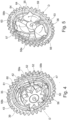
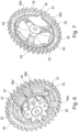
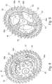
- the gear wheel contour 50 of the output 29 is offset in height to the gear wheel contour 39 of the drive 28 (see Fig. 4 ).
- Gear wheel contour 51 of output 29 preferably protrudes beyond the surface of annular plate element 43 of drive 28.
- a rolling surface 64 of the rolling element 36 is preferably of cylindrical design.
- the rolling element is designed in particular as a hollow cylinder.
- the rolling element 36 is preferably arranged on the base surface 54 of the cylindrical region 48 of the output 29 (see Fig. figure 5 ).
- the rolling element 36 is preferably firmly connected to the coupling element 33 and is designed to be immovable.
- a connecting element 56 can be arranged in the cavity 55 of the hollow cylinder of the rolling element 36, which connects the rolling element 36 to the output 29 (see Fig. Figures 4 and 5 ), wherein only the output 29 can be rotated about the connecting element 56 .
- the pawl 30 preferably includes a connecting portion 57, a pawl portion 58a, 58b and a guide portion 59.
- the pawl 30 is preferably mirror symmetrical is formed, wherein advantageously the mirror plane runs through the center of the pawl 30.
- the mirror plane preferably runs centrally through the connecting section 57 and the guide section 59.
- the pawl 30 has, for example, two identical halves.
- the pawl 30 is preferably arranged between the drive 28 and the output 29, with the connecting section 57 of the pawl 30 being accommodated in the recess 42 of the drive 28 and the pawl section 58a, 58b being arranged on the lateral surface 51 of the cylindrical region 48 of the output 29 .
- the connecting section 57 is preferably formed centrally on the pawl 30 and is used to accommodate the pawl in the recess 42 of the drive 28 .
- the shape of the recess 42 is preferably adapted to the outer contour of the connecting section 57 .
- the area 60 of the connecting section 57, which rests in the semicircular recess 42 or on the bearing surface 46 of the drive 28, is preferably convex (see Fig. 4 ).
- the connecting section 57 of the pawl 30 preferably has a projection 61, the projection 61 being designed, for example, in the shape of a trapezium.
- the connecting section 57 preferably rests with its projection 61 on the upper side 47 of the hollow cylinder 38 of the drive 28 (see Fig. 4 ).
- a support surface 62 which is convex, for example, is preferably formed on the connecting section 57 .
- the bearing surface 62 is preferably opposite the area 60 of the connecting portion 57 which bears in the recess 42 in the drive 28 .
- the bearing surface 62 of the connecting section 57 is preferably in contact with the inner lateral surface 40 of the hollow cylinder 38 of the toothed wheel area 37 of the drive 28 .
- the pawl 30 preferably includes two pawl portions 58a, 58b, with the pawl portions 58a, 58b being located at opposite ends of the pawl 30. As shown in FIG.
- the pawl 30 is advantageously configured in such a way that the first pawl section 58a hooks into a recess 52 on the output 29 when the drive 28 rotates to the right, and the second pawl section 58b hooks into a recess 52 on the output 29 when the drive 28 rotates to the left .
- the guide section 59 of the pawl 30 advantageously dips into the guide track 53 and is, for example, completely accommodated in the guide track 53 (see Fig. figure 5 ).
- the guide section 59 preferably has an approximately triangular shape or is designed approximately as an isosceles triangle, with the legs being slightly curved outwards or convex.
- the other side of the guide section 59 preferably has a rolling surface 63 .
- the rolling surface 63 of the pawl 30 preferably rests permanently on the cylindrical rolling surface 64 of the rolling element 36 (see Fig. figure 5 , 7 , 9 ).
- the spring element 35 is preferably designed as an approximately circular spring wire, with the spring element 35 having a distance between the beginning section and the end section, so that the spring element 35 can be narrowed and widened.
- the spring element 35 preferably rests on the bearing surface 62 of the connecting section 57 of the pawl 30 .
- the spring element 35 is preferably loaded or prestressed in the direction of the output 29 , as a result of which the rolling surface 63 of the pawl 30 is permanently pressed against the rolling element 36 or the rolling surface 64 of the rolling element 36 .
- the spring element 35 is advantageously arranged between the projection 61 of the connecting section 57 of the pawl 30 and the upper side 47 of the hollow cylinder 38 of the gear wheel area 37 of the drive 28 (see Fig. 4 ).
- the pawls 30 are preferably rotated in the same direction of rotation as the drive 28, about the axis of rotation D, by receiving the connecting portion 57 of the pawls 30 in the recesses 42 on the drive 28.
- the axis of rotation D advantageously runs parallel to the height of the cylindrical region 48 of the output 29.
- a first pawl section 58a of the pawls 30 each reach a recess 52 on the output 29, as a result of which the output 29 is coupled to the drive 28 (see Fig. Figures 4 and 5 ).
- the input 28, the pawls 30 and the output 29 are rotated in the coupled state in the same direction of rotation with the same torque.
- the pawl sections 58a, 58b of the pawl 57 can be moved or pivoted out of the recesses 52 if the output 29 is moved faster than the drive 28 in the direction of rotation or if the drive 28 stops and the output 29 is moved. Decoupling is also possible if the output 29 stops. This can preferably happen when a user moves the movable furniture part 3 in the opening or closing direction faster than specified by the motor 23 or holds the movable furniture part 3 in place.
Landscapes
- Engineering & Computer Science (AREA)
- Mechanical Engineering (AREA)
- General Engineering & Computer Science (AREA)
- Power-Operated Mechanisms For Wings (AREA)
- Transmission Devices (AREA)
Abstract
Description
- Es sind bereits Sperrklinkenkupplungen bekannt, bei welchen ein Antrieb und ein Abtrieb in eine Drehrichtung koppeln und in die andere Drehrichtung entkoppeln. Nachteilig an den bekannten Kupplungen ist, dass die Kopplung des Antriebs mit dem Abtrieb nur in eine Drehrichtung stattfinden kann.
- Aufgabe der Erfindung ist es, eine verbesserte Sperrklinkenkupplung mit einem Antrieb und einem Abtrieb bereitzustellen, insbesondere im Hinblick auf eine kompakte und einfache Bauweise.
- Die Aufgabe wird durch die Merkmale der unabhängigen Ansprüche gelöst.
- Vorteilhafte und zweckmäßige Ausführungsformen, Varianten und Weiterbildungen der Erfindung sind in den abhängigen Ansprüchen ausgeführt.
- Die Erfindung geht aus von einer Kupplung mit einem Antrieb, einem Abtrieb und einer Sperrklinke.
- Dabei sind der Antrieb, der Abtrieb und die Sperrklinke vorzugsweise als separate Bauteile ausgebildet. Der Antrieb, der Abtrieb und die Sperrklinken sind bevorzugterweise lösbar miteinander verbindbar.
- Der Kern der Erfindung ist, dass die Sperrklinke mit dem Antrieb verbunden ist und zwischen Antrieb und Abtrieb angeordnet ist, wobei durch die Bewegung des Antriebs die Sperrklinke schwenkkbar ist, wobei die Sperrklinke derart ausgelegt ist, in beide Drehrichtungen eine Kopplung mit dem Abtrieb herbeizuführen, wenn der Antrieb eine Drehbewegung ausführt und eine Entkopplung ermöglicht ist, wenn der Antrieb steht und der Abtrieb eine Drehbewegung ausführt.
- Weiter umfasst vorteilhafterweise der Antrieb ein Zahnradbereich, wobei der Zahnradbereich vorzugsweise als Hohlzylinder ausgebildet ist. Dabei weist die äußere Mantelfläche des Hohlzylinders des Zahnradbereichs des Antriebs vorzugsweise eine Zahnradkontur auf und die innere Mantelfläche des Hohlzylinders des Zahnradbereichs ist konkav ausgestaltet. Bevorzugterweise ist an der inneren Mantelfläche des Hohlzylinders des Zahnradbereichs eine ringförmige Platte angeordnet, welche umfänglich an der inneren Mantelfläche des Hohlzylinders des Zahnradbereichs anliegt. Die ringförmige Platte ist vorzugsweise höhenversetzt zur Zahnradkontur des Hohlzylinders des Zahnradbereichs am Antrieb ausgebildet. Weiter weist die Oberfläche, welche beispielsweise streifenförmig ist, der ringförmigen Platte in die gleiche Richtung, wie die Zahnradkontur des Hohlzylinders des Zahnradbereichs.
- An der Oberfläche der ringförmigen Platte ist vorzugsweise zumindest eine Ausnehmungen zur Aufnahme der Sperrklinke ausgebildet. Die Länge der Ausnehmung erstreckt sich vorzugsweise axial zu einer Drehachse, um welche der Antrieb und der Abtrieb gedreht werden, an der Oberfläche der ringförmigen Platte. Die Drehachse verläuft bevorzugterweise mittig durch den Antrieb und Abtrieb. Die Oberfläche der ringförmigen Platte weist für die Ausnehmungen Aussparungen bzw. Lücken in der Oberfläche der ringförmigen Platte auf. Weiter folgt vorzugsweise an der Oberfläche der ringförmigen Platte ein kreisringförmiges Plattenelement, wobei die Oberfläche des kreisringförmigen Plattenelements senkrecht zur Oberfläche der ringförmigen Platte ausgerichtet ist. Bevorzugterweise ist ein Winkel von 85°-95° zwischen der Oberfläche der ringförmigen Platte und der Oberfläche des kreisringförmigen Plattenelements eingeschlossen. Der Durchmesser der inneren Mantelfläche des Hohlzylinders des Zahnradbereichs, wobei die innere Mantelfläche des Hohlzylinders des Zahnradbereichs gegenüberliegend zur Zahnradkontur ausgebildet ist, ist vorzugsweise größer als der Durchmesser einer Innenkontur des kreisringförmigen Plattenelements. Das kreisringförmige Plattenelement weist vorzugsweise zwei umlaufende Endkanten mit unterschiedlichen Radien auf, wobei eine Endkante mit der Oberfläche der ringförmigen Platte verbunden ist und die andere Endkante vorzugsweise die Innenkontur des kreisringförmigen Plattenelements aufweist. Die beiden Endkanten sind vorzugsweise gegenüberliegend an der kreisringförmigen Oberfläche des Plattenelements ausgestaltet.
- In dem kreisringförmigen Plattenelement, insbesondere in der Oberfläche des kreisringförmigen Plattenelements, ist die Ausnehmung im Antrieb vorzugsweise halbkreisförmig bzw. konkav ausgebildet. Dabei entsteht eine Lücke bzw. Aussparung an der Endkante, welche mit der Oberfläche der ringförmigen Platte verbunden ist, so dass für die Sperrklinke eine Auflagefläche entsteht. Vorteilhafterweise ist die Ausnehmung in dem kreisringförmigen Plattenelement als Aussparung bzw. Lücke ausgebildet. Bevorzugterweise sind im Antrieb mehrere Ausnehmungen vorhanden, wobei die Anzahl der Ausnehmungen im Antrieb vorzugsweise auf die Anzahl der Sperrklinken abgestimmt ist. Dabei sind die Ausnehmungen gleichmäßig verteilt an der ringförmigen Platte und dem kreisringförmigen Plattenelements ausgebildet. Ist die Anzahl der Sperrklinken beispielsweise drei, dann sind die Ausnehmungen z.B. 120° voneinander beabstandet. Bevorzugterweise weist die Kupplung drei oder mehr Sperrklinken auf, die untereinander gleich vorzugsweise identisch ausgestaltet sind.
- Vorteilhafterweise ist ein Teil des Abtriebs zwischen der Innenkontur des kreisringförmigen Plattenelements und der inneren Mantelfläche des Hohlzylinders des Zahnradbereichs des Antriebs aufgenommen. Ein Teil der Sperrklinken liegt vorzugsweise in der Ausnehmung des Antriebs auf, wobei ein anderer Teil der Sperrklinke zwischen dem Antrieb und dem Abtrieb angeordnet ist. Dabei kann die Sperrklinke durch eine Schwenkbewegung vorteilhafterweise mit dem Abtrieb koppeln oder entkoppeln.
- Vorteilhafterweise ist der Antrieb in beide Drehrichtungen um eine Drehachse, z.B. durch einen Motor, drehbar, wobei bei der Drehbewegung des Antriebs die Sperrklinken in die Drehrichtung des Antriebs mitbewegbar sind. Dies geschieht dadurch, dass die Sperrklinken vorzugsweise fest mit dem Antrieb durch die Aufnahme der Sperrklinken in den Ausnehmungen des Antriebs verbunden sind. Dabei kann die Sperrklinke mit dem Abtrieb koppeln, so dass der Abtrieb durch die Sperrklinken vorteilhafterweise in die gleiche Richtung, wie der Antrieb drehbar ist.
- Ist der Abtrieb vom Antrieb entkoppelt, koppelt die Sperrklinke nicht mit dem Abtrieb, so dass der Abtrieb vorteilhafterweise in beide Drehrichtungen relativ zum Antrieb bewegbar ist. Es findet vorteilhafterweise keine Antriebsbewegung über den Abtrieb statt.
- Von Vorteil ist, dass die Kupplung einen einzigen Abtrieb aufweist, wobei der Abtrieb in beide Drehrichtungen drehbar ist.
- Der Abtrieb ist vorzugsweise als ein einziges Bauteil ausgebildet. Bevorzugterweise weist der Abtrieb einen zylindrischen Bereich auf, wobei an einer kreisförmigen Grundfläche des zylindrischen Bereichs des Abtriebs beispielsweise ein Zahnrad mit Zahnradkontur ausgebildet ist. Der Abtrieb ist vorzugsweise in einem Innenraum des Antriebs angeordnet, wobei die Mantelfläche des zylindrischen Bereichs des Abtriebs vorteilhafterweise gegenüberliegend zur Oberfläche der ringförmigen Platte des Antriebs angeordnet ist. Vorteilhafterweise ist die Zahnradkontur des Abtriebs höhenversetzt bzw. in einer unterschiedlichen Ebene zur Zahnradkontur des Antriebs angeordnet. Die Zahnradkontur des Antriebs und die Zahnradkontur des Abtriebs sind vorteilhafterweise in die gleiche Richtung ausgerichtet. Bevorzugterweise überragt die Zahnradkontur des Abtriebs die Oberfläche des kreisringförmigen Plattenelements des Antriebs.
- Vorteilhafterweise ist der Abtrieb symmetrisch, insbesondere drehsymmetrisch, ausgebildet, wobei beispielsweise der Abtrieb drehsymmetrisch zur Drehachse ist. Der Abtrieb ist vorteilhafterweise in beide Drehrichtungen drehbar. Vorteilhafterweise verläuft die Drehachse mittig durch den zylindrischen Bereich des Abtriebs, insbesondere parallel zur Höhe des zylindrischen Bereichs des Abtriebs. Durch die symmetrische Ausbildung des Abtriebs ist die Kopplung und Entkopplung mit dem Antrieb in beide Drehrichtungen möglich, wobei vorteilhafterweise nur ein einziger Abtrieb benötigt wird.
- Von Vorteil ist, dass die Sperrklinke einen Verbindungabschnitt aufweist, wobei die Sperrklinke mittels des Verbindungsabschnitts am Antrieb angeordnet ist.
- An den Sperrklinken ist vorzugsweise mittig ein Verbindungsabschnitt ausgebildet, mit welchem die Sperrklinke in der Ausnehmung des Antriebs aufgenommen ist. Bevorzugterweise ist die Form der Ausnehmung auf die Außenkontur des Verbindungsabschnitts angepasst. Der Bereich des Verbindungsabschnitts, welcher in der z.B. halbkreisförmigen Ausnehmung bzw. auf der Auflagefläche des Antriebs aufliegt, ist vorzugsweise konvex ausgebildet. Somit ist vorteilhafterweise gewährleistet, dass die Sperrklinken mit dem Verbindungsabschnitt in der Ausnehmung des Antriebs, z.B. passgenau anliegend, aufgenommen werden kann.
- Weiter weist vorzugweise der Verbindungabschnitt der Sperrklinke einen Vorsprung auf, wobei der Vorsprung beispielsweise trapezförmig ausgestaltet ist. Der Verbindungsabschnitt liegt vorzugsweise mit seinem Vorsprung an einer Oberseite des Hohlzylinders des Zahnradbereichs an. Die Oberseite des Hohlzylinders des Zahnradbereichs ist bevorzugterweise senkrecht zur Zahnradkontur des Antriebs und parallel zur Oberfläche des kreisringförmigen Plattenelements ausgestaltet. Weiter ist beispielsweise der Vorsprung radial von der Drehachse in Richtung der Zahnradkontur des Antriebs ausgerichtet.
- An dem Verbindungsabschnitt ist vorzugsweise eine beispielsweise konvexe Auflageoberflächen ausgebildet. Die Auflageoberfläche ist bevorzugterweise gegenüberliegend zum Bereich des Verbindungsabschnitts, welcher in der Ausnehmung im Antrieb aufliegt. Die Auflageoberfläche des Verbindungsabschnitts liegt vorzugsweise an der inneren Mantelfläche des Hohlzylinders des Zahnradbereichs an.
- Vorteilhafterweise weist der Abtrieb eine Aussparung auf, wobei beim Kuppeln des Antriebs mit dem Abtrieb ein Klinkenabschnitt der Sperrklinke in die Aussparung eingreift.
- Vorteilhafterweise weist der Abtrieb einen zylindrischen Bereich auf, wobei die Mantelfläche des zylindrischen Bereichs des Abtriebs zur Oberfläche der ringförmigen Platte des Antriebs ausgerichtet ist. An der Mantelfläche des zylindrischen Bereichs ist vorzugsweise die Aussparung ausgebildet, wobei bevorzugterweise mehrere Aussparungen an der Mantelfläche des zylindrischen Bereichs des Abtriebs ausgebildet sind. Die Aussparungen sind vorteilhafterweise gleichmäßig an der Mantelfläche des zylindrischen Bereichs des Abtriebs verteilt, wobei die Aussparungen vorzugsweise gleich ausgebildet sind. Die Aussparungen sind vorzugsweise vertieft bzw. versenkt in der Mantelfläche im Abtrieb ausgebildet, wobei die Aussparungen eine gleiche Tiefe, Länge und aufweisen. Dabei sind die Aussparungen bevorzugterweise gleich bzw. identisch untereinander in der Mantelfläche des Abtriebs ausgebildet.
- Die Sperrklinke bzw. der Klinkenabschnitt der Sperrklinke ist vorzugsweise zwischen der Mantelfläche des zylindrischen Bereichs des Abtriebs und der streifenförmigen Oberfläche der ringförmigen Platte des Antriebs angeordnet, so dass der Klinkenabschnitt der Sperrklinke in eine Aussparung eingreifen kann. Der Klinkenabschnitt kann durch die Schwenkbewegung der Sperrklinke in die Aussparung am Abtrieb eingreifen, wodurch eine Kupplung des Antriebs mit dem Abtrieb herstellbar ist.
- Ebenfalls ist es von Vorteil, dass die Sperrklinke zwei Klinkenabschnitte aufweist, wobei die Klinkenabschnitte an zwei sich gegenüberliegenden Endbereichen der Sperrklinke angeordnet sind.
- Die Sperrklinke weist vorzugsweise zwei Klinkenabschnitte auf, wobei die Klinkenabschnitte an umfänglich zur Drehachse gegenüberliegenden Enden der Sperrklinke angeordnet sind. Vorteilhafterweise ist die Sperrklinke derart ausgestaltet, dass der erste Klinkenabschnitt bei einer Drehung des Antriebs nach rechts in eine Aussparung am Abtrieb eingreift und der zweite Klinkenabschnitt bei einer Drehung des Antriebs nach links in eine Aussparung am Abtrieb eingreift.
- Ebenfalls ist es vorteilhaft, dass die Kupplung ein feststehendes Abrollelement umfasst, wobei am Abrollelement eine Abrollfläche der Sperrklinke abrollt, wobei die Abrollfläche am Abrollelement in beide Drehrichtungen abrollbar ist, so dass die Sperrklinke in beide Drehrichtungen schwenkbar ist.
- Bevorzugterweise ist eine Wälzfläche des Abrollelements zylindrisch ausgebildet. Das Abrollelement ist insbesondere als Hohlzylinder ausgebildet. Bevorzugterweise ist das Abrollelement an einer Grundfläche des zylindrischen Bereichs des Abtriebs angeordnet, wobei die Grundfläche gegenüberliegend zur Grundfläche ist, an der die Zahnradkontur am Antrieb ausgebildet ist. Das Abrollelement ist vorzugsweise fest und unbeweglich ausgebildet, wobei das Abrollelement beispielsweise fest an einem Möbelkorpus angeordnet ist.
- Bevorzugterweise liegt an der Wälzfläche des Abrollelements die Abrollfläche der Sperrklinke auf. Die Abrollfläche der Sperrklinke liegt bevorzugterweise dauerhaft am Abrollelement bzw. an der Wälzfläche des Abrollelements an. Die Abrollfläche der Sperrklinke, welche an dem Abrollelement aufliegt, ist bevorzugterweise konvex ausgestaltet, so dass der konvexe Bereich der Abrollfläche der Sperrklinke auf der konvexen Wälzfläche des Abrollelements aufliegt. Dadurch kann vorteilhafterweise die Abrollfläche der Sperrklinke in beide Drehrichtung am Abrollelement abrollen, so dass die Sperrklinke in beide Drehrichtungen verschwenkbar ist. Dabei kann vorzugsweise die Sperrklinke bzw. die Klinkenabschnitte der Sperrklinke in die Ausnehmung im Abtrieb hereingeschwenkt oder herausgeschwenkt werden. So kann vorteilhafterweise die Kopplung und die Entkopplung des Antriebs mit dem Abtrieb in beide Drehrichtungen erfolgen.
- Vorteilhafterweise ist im entkoppelten Zustand der Kupplung der Klinkenabschnitt der Sperrklinke nicht im Eingriff mit der Aussparung des Abtriebs.
- Im entkoppelten Zustand der Kupplung kann bevorzugterweise der Abtrieb unabhängig vom Antrieb in beide Drehrichtungen bewegt werden. Zum Entkoppeln der Kupplung sollte der Antrieb in entgegengesetzter Richtung zur vorangegangenen Drehrichtung kurz gedreht werden, so dass die Klinkenabschnitte der Sperrklinke verschwenkt werden und nicht mehr im Eingriff mit den Aussparungen am Abtrieb sind. Dies geschieht beispielsweise in dem die Drehrichtung eines Motors, insbesondere eines elektrischen Motors, geändert bzw. umgekehrt wird.
- Weiter können die Klinkenabschnitte der Sperrklinke aus den Aussparungen herausbewegt bzw. herausgeschwenkt werden, wenn der Abtrieb schneller als der Antrieb in Drehrichtung bewegt wird oder wenn der Antrieb stehen bleibt und der Abtrieb bewegt wird. Vorteilhafterweise weist die Kupplung ein Federelement auf, wobei das Federelement die Sperrklinke gegen das Abrollelement drückt.
- Das Federelement ist vorzugsweise als annähernd kreisförmiger Federdraht ausgebildet, wobei das Federelement einen Abstand zwischen Anfangsabschnitt und Endabschnitt aufweist, so dass das Federelement verengt und geweitet werden kann. Das Federelement liegt vorzugsweise auf der Auflageoberfläche des Verbindungsabschnitts der Sperrklinke auf. Das Federelement ist vorzugsweise in Richtung des Abtriebs geladen bzw. vorgespannt, wodurch die Sperrklinke bzw. die Abrollfläche der Sperrklinke gegen das Abrollelement bzw. die Wälzfläche des Abrollelements gedrückt, insbesondere dauerhaft gedrückt, wird.
- Vorteilhafterweise ist das Federelement zwischen dem Vorsprung des Verbindungsabschnitts der Sperrklinke und der Oberseite des Hohlzylinders des Zahnradbereichs des Antriebs angeordnet. Dadurch ist vorteilhafterweise gewährleistet, dass das Federelement zwischen Antrieb und Sperrklinke eingeklemmt ist und die Sperrklinke beispielsweise dauerhaft gegen das Abrollelement drückt.
- Auch ist es vorteilhaft, dass der Abtrieb eine Führungsbahn aufweist, wobei ein Führungsabschnitt der Sperrklinke in der Führungsbahn des Abtriebs angeordnet ist.
- Bevorzugterweise ist die Führungsbahn als rillenförmige Vertiefung im Abtrieb ausgebildet. Die Vertiefung der Führungsbahn ist vorzugsweise ringförmig und an einer Grundfläche des zylindrischen Bereichs des Abtriebs vertieft ausgebildet. Die Grundfläche, welche die Führungsbahn aufweist, ist vorzugsweise gegenüberliegend zur Grundfläche an welcher das Zahnrad mit Zahnradkontur des Abtriebs ausgebildet ist. Beispielsweise liegt an einem Randabschnitt der Vertiefung der Führungsbahn das Abrollelement an. Die Vertiefung weist vorzugsweise zwei kreisförmige Randabschnitte auf, wobei der Randabschnitt, an welchem das Abrollelement anlieft, beispielsweise radial näher zur Drehachse ist.
- Der Führungsabschnitt der Sperrklinke taucht vorteilhafterweise in die Führungsbahn ein und wird beispielsweise komplett in der Führungsbahn aufgenommen. Der Führungsabschnitt der Sperrklinke hat vorzugsweise eine annähernd dreieckige Form bzw. ist annähernd als gleichschenkliges Dreieck ausgebildet, wobei die Schenkel leicht nach außen gewölbt bzw. konvex sind. Die dritte Seite des Führungsabschnitts weist vorzugsweise die Abrollfläche auf.
- Auch ist es vorteilhaft, dass die Sperrklinke spiegelsymmetrisch ausgebildet ist.
- Vorteilhafterweise verläuft die Spiegelebene mittig durch den Verbindungsabschnitt und den Führungsabschnitt, so dass die Spiegelebene die Sperrklinke in zwei gleiche Hälften teilt. Durch die Spiegelsymmetrie der Sperrklinke und der drehsymmetrischen Ausbildung des Abtriebs ist es vorteilhafterweise möglich, dass die Kopplung des Antriebs mit dem Abtrieb durch die Sperrklinke in beide Drehrichtungen erfolgen kann.
- Eine vorteilhafte Ausführungsform der Erfindung ist eine Antriebsvorrichtung mit einem elektrischen Motor zum Bewegen eines beweglichen Möbelteils relativ zu einem Möbelkorpus, wobei das Drehmoment des Motors auf ein Möbelbeschlag übertragbar ist, wobei die Drehbewegung des Motors eine Bewegung des Möbelbeschlags und damit des beweglichen Möbelteils in Öffnungs- und Schließrichtung bewirkt, wobei die Antriebsvorrichtung eine Kupplung nach einer der vorangegangen beschriebenen Ausführungen aufweist.
- Vorteilhafterweise ist die Antriebsvorrichtung am Möbelbeschlag vormontiert. Vorstellbar ist es auch die Antriebsvorrichtung nachträglich an einen bestehenden Möbelbeschlag, der ohne Antriebsvorrichtung bzw. herkömmlich gestaltet ist, zu montieren. Der Möbelbeschlag ist vorzugsweise für eine Klappe, insbesondere Oberklappe, oder Schranktüre ausgebildet. Bevorzugterweise weist die Antriebsvorrichtung für das Anbringen an den Möbelbeschlag ein Kopplungselement auf, welches z.B. über Schrauben mit einem Gehäuse des Möbelbeschlags verbindbar ist. Das Kopplungselement kann beispielsweise als Platte oder Gehäuse ausgebildet sein, wobei vorzugsweise die Bestandteile der Antriebsvorrichtung an dem oder in dem Kopplungselement aufgenommen sind. Bevorzugterweise ist das Abrollelement der Kupplung fest mit dem Gehäuse bzw. dem Kopplungselement der Antriebsvorrichtung verbunden. Vorteilhafterweise weist der Möbelbeschlag ein Gehäuse auf, wobei das Gehäuse des Möbelbeschlags als auch das Kopplungselement z.B. in einer Vertiefung in einer Seitenwand des Möbelkorpus aufnehmbar ist, insbesondere so dass das Gehäuse des Möbelbeschlags und das Kopplungselements bündig mit der Oberfläche der Seitenwand abschließen bzw. gering versenkt zur Oberfläche der Seitenwand sind.
- Bevorzugterweise weist die Antriebsvorrichtung ein Getriebe auf, wobei das Getriebe vorzugsweise zumindest ein Übertragungselement, wie. z.B. ein Zahnrad, aufweist. Bevorzugterweise weist das Getriebe mehrere Übertragungselemente auf. Die Übertragungselemente sind vorzugsweise als Doppelzahnrad ausgebildet.Bei einem Doppelzahnrad sind vorzugsweise ein größeres Zahnrad und ein kleineres Zahnrad übereinander angeordnet.
- Vorteilhafterweise ist das Drehmoment des Motors auf das Getriebe übertragbar, wobei nach dem Motor abtriebseititg vorzugsweise Übertragungselemente folgen, wobei ein Übertragungselement bevorzugterweise in die Kupplung eingreift. Weiter ist vorstellbar, dass die Antriebsvorrichtung kein Getriebe aufweist, sondern beispielsweise eine Antriebswelle des Motors direkt in die Kupplung eingreift bzw. auf die Kupplung wirkt zur Drehmomentsübertragung.
- Bevorzugterweise weist die Antriebsvorrichtung einen Hebel auf, wobei der Hebel vorteilhafterweise mit einem Teil des Möbelbeschlags verbindbar, insbesondere lösbar verbindbar ist, beispielsweise über Verbindungsmittel, wie z.B. Schrauben. Beispielsweise kann der Hebel mit einem Arm bzw. Schwenkarm des Möbelbeschlags verbunden werden. Der Hebel ist bevorzugterweise nach der Kupplung angeordnet und vorzugsweise mit dem Abtrieb der Kupplung verbunden. Nach der Kupplung kann auch ein weiteres Übertragungselement folgen, wobei dann der Hebel vorzugsweise mit dem Übertragungselement verbunden ist. Dabei wird der Hebel vorzugsweise durch die Drehbewegung des Übertragungselements oder der Kupplung verschwenkt. Somit ist der Hebel an einem Ende mit dem Arm bzw. Schwenkarm des Möbelbeschlags und an dem anderen Ende mit dem Übertragungselement oder mit der Kupplung, insbesondere dem Abtrieb der Kupplung, verbunden, vorzugsweise lösbar verbunden. Der Hebel der Antriebsvorrichtung kann auch nachträglich mit dem Arm des Möbelbeschlags verbunden werden. Somit kann vorteilhafterweise ein Möbel nachträglich mit einer Antriebsvorrichtung zum motorischen Bewegen des Möbelbeschlags bzw. des beweglichen Möbelteils ausgestattet werden.
- Die Drehbewegung des Motors wird auf das Getriebe im Betrieb übertragen, wobei der Hebel bewegt wird, wodurch mittels des Möbelbeschlags das bewegliche Möbelteil in Öffnung- und Schließrichtung bewegbar ist. Bevorzugterweise wird eine Drehbewegung des Motors über das Getriebe auf den Antrieb der Kupplung übertragen, wobei in der gekoppelten Stellung der Kupplung die Drehbewegung vom Antrieb über das Federelement auf den Abtrieb übertragen wird, wobei der Abtrieb die Drehbewegung auf den Hebel und somit auf den Möbelbeschlag überträgt. Bevorzugterweise wird über die Drehbewegung des Möbelbeschlags bzw. eines drehbaren Teils des Möbelbeschlags das bewegliche Möbelteil in Öffnungs- und Schließrichtung bewegt, je nach Drehrichtung des Teils des Möbelbeschlags. Vorteilhafterweise kann der Motor in beide Drehrichtungen rotieren, so dass der Möbelbeschlag bzw. das bewegliche Möbelteil über die Antriebsvorrichtung in Öffnungs- und Schließrichtung angetrieben bewegbar ist.
- Eine weitere vorteilhafte Ausführungsform der Erfindung ist eine Beschlaganordnung mit einem Möbelbeschlag zum Bewegen eines beweglichen Möbelteils relativ zum Möbelkorpus und einer Antriebsvorrichtung nach einer der vorangegangen beschriebenen Ausführungen zum angetriebenen Bewegen des Möbelbeschlags.
- Die Beschlaganordnung umfasst vorzugsweise einen Möbelbeschlag und die Antriebsvorrichtung, wobei bevorzugterweise der Hebel der Antriebsvorrichtung mit einem Arm, insbesondere einem Schwenkarm, des Möbelbeschlags verbunden ist. Dadurch kann vorteilhafterweise die vom Motor erzeugte Drehbewegung einer Antriebswelle des Motors durch den Hebel auf den Möbelbeschlag übertragen werden, wodurch der Möbelbeschlag angetrieben bewegbar ist. Bevorzugterweise kann die Bewegung des Möbelbeschlags auf das bewegliche Möbelteil in Öffnungs- und Schließrichtung übertragen werden, so dass das bewegliche Möbelteil angetrieben abhängig von der Drehrichtung in Öffnungs- und Schließrichtung bewegbar ist.
- Bevorzugterweise ist zwischen dem Hebel und dem elektrischen Motor ein Getriebe mit mehreren Übertragungselementen und zumindest eine Kupplung angeordnet, wobei die Drehbewegung des Motors über die Übertragungselemente und der gekoppelten Kupplung auf den Hebel übertragen werden kann, wodurch der Möbelbeschlag verschwenkt oder linear bewegt werden kann. Der Möbelbeschlag weist vorzugsweise mehrere Arme bzw. Schwenkarme auf, wobei zumindest ein Schwenkarm mit dem beweglichen Möbelteil und zumindest ein Schwenkarm mit dem Möbelkorpus verbunden ist. Bevorzugterweise verursacht die Bewegung, wie z.B. eine Schwenkbewegung, eines Arms bzw. Schwenkarms des Möbelbeschlags die Bewegung der anderen Arme bzw. Schwenkarme. Die Arme bzw. die Schwenkarme des Möbelbeschlags sind vorzugsweise schwenkbar miteinander verbunden.
- Vorstellbar ist, dass eine Bedienperson die Öffnungs- und Schließbewegung des beweglichen Möbelteils durch Aktivieren des elektrischen Motors auslöst. Das Aktivieren des elektrischen Motors kann über ein Auslösen einen Schalters erfolgen, beispielsweise kann ein Schalter an einer Stirnseite einer Wand des Möbelkorpus angeordnet sein, wobei beim Andrücken des beweglichen Möbelteils durch die Bedienperson gegen den Möbelkorpus der Schalter aktiviert wird. Eine weitere Möglichkeit besteht darin, dass eine Bedienperson den elektrischen Motor über eine Fernbedienung aktiviert.
- Eine weitere vorteilhafte Ausführungsform der Erfindung ist ein Möbel mit einer Beschlaganordnung nach einer der vorangegangen beschriebenen Ausführungen, wobei durch die Beschlaganordnung ein bewegliches Möbelteil relativ zu einem Möbelkorpus motorisch angetrieben bewegbar ist.
- Weitere Merkmale und Vorteile der Erfindung sind anhand eines in den Figuren schematisiert dargestellten Ausführungsbeispiels näher erläutert.
- Im Einzelnen zeigt:
- Figur 1
- eine perspektivische Ansicht auf ein Möbel mit einem Möbelbeschlag zur Bewegung eines geöffnet dargestellten beweglichen Möbelteils des Möbels,
- Figur 2
- eine Seitenansicht auf eine erfindungsgemäße Beschlaganordnung ohne eine Abdeckung der Beschlaganordnung,
- Figur 3
- eine Explosionsdarstellung einer Kupplung der Beschlaganordnung gemäß
Fig. 2 , - Figur 4
- eine perspektivische Ansicht von schräg oben auf eine Vorderseite der zusammengebauten Kupplung gemäß
Figur 3 in gekoppelter Stellung bei einer Drehung in eine erste Drehrichtung, - Figur 5
- eine perspektivische Ansicht von schräg oben auf eine Rückseite der Kupplung gemäß
Figur 4 in gekoppelter Stellung bei einer Drehung in eine erste Drehrichtung, - Figur 6
- eine perspektivische Ansicht von schräg oben auf eine Vorderseite der Kupplung gemäß
Figur 4 in nicht gekoppelter Stellung, - Figur 7
- eine perspektivische Ansicht von schräg oben auf eine Rückseite der Kupplung gemäß
Figur 5 in nicht gekoppelter Stellung, - Figur 8
- eine perspektivische Ansicht von schräg oben auf eine Vorderseite der Kupplung gemäß
Figur 4 und6 in gekoppelter Stellung bei einer Drehung in eine zweite Drehrichtung, - Figur 9
- eine perspektivische Ansicht von schräg oben auf eine Rückseite der Kupplung gemäß
Figur 5 und7 in gekoppelter Stellung bei einer Drehung in eine zweite Drehrichtung. -
Fig. 1 zeigt perspektivisch ein Möbel 1 mit einem kastenförmigen Möbelkorpus 2 und einem daran aufgenommenen beweglichen Möbelteil 3, welches vorzugsweise als Klappe bzw. Oberklappe ausgebildet, und in einer Offenstellung relativ zum Möbelkorpus 2 gezeigt ist. Das Möbel 1 ist beispielsweise als Oberklappenschrank ausgebildet z.B. an einer Wand hängend befestigt. - Der vorne offene Möbelkorpus 2 umfasst zwei gegenüberliegende aufrechte Seitenwände 4 und 5, die unten mit einem Unterboden 6 und oben mit einem Oberboden 7 verbunden sind. Rückseitig ist der Möbelkorpus 2 von einer Rückwand 8 verschlossen. Zur Bewegung des beweglichen Möbelteils 3 um eine horizontale Schwenkachse, relativ zum Möbelkorpus 2 aus der in
Fig. 1 gezeigten Offenstellung in eine zum Möbelkorpus 2 frontseitig heranbewegte Schließstellung (nicht gezeigt) und zurück in die Offenstellung gemäßFig. 1 ist ein Möbelbeschlag 9 vorhanden, welcher vorzugsweise als Oberklappenbeschlag ausgestaltet ist. Der Möbelbeschlag 9 weist an der Seitenwand 4 eine erste Beschlageinheit 10 und an der Seitenwand 5 eine zweite Beschlageinheit 11 auf. Die Beschlageinheiten 10, 11 sind gleichartig und zur funktionsrichtigen Anordnung an der jeweiligen Seitenwand 4 bzw. 5 seitenbezogen aufgebaut. - Jede Beschlageinheit 10 und 11 umfasst eine Basiseinheit 12, eine Schwenkarm-Anordnung 13 und eine Montageeinheit 14. Über mehrere gelenkig gelagerte Schwenkarme 15 der Schwenkarm-Anordnung 13 ist die Basiseinheit 12 mit der Montageeinheit 14 verbunden, wobei die Montageeinheit 14 fest an einer Innenseite des beweglichen Möbelteils 3 beispielsweise versenkt in einer Materialausnehmung des beweglichen Möbelteils 3 befestigt ist. Die Basiseinheit 12 ist vorzugsweise als ein Gehäuse 19 ausgebildet und umfasst eine ebene, flache bzw. dünne Grundplatte 16 und ein der Grundplatte 16 gegenüberliegendes Abdeckbauteil 20. Weiter ist vorzugsweise stirnseitig an der Basiseinheit 12 ein Stirnabschnitt 17 vorhanden, dessen Außenseite quer zur Ebene der Grundplatte 16 ausgerichtet ist. Durch eine rechteckförmige Aussparung 18 in dem Stirnabschnitt 17 greifen bevorzugterweise zumindest ein betreffender Schwenkarm 15 der Schwenkarm-Anordnung 13.
- In der
Figur 2 ist eine Beschlaganordnung 21 dargestellt, welche den Möbelbeschlag 9 und eine Antriebsvorrichtung 22 umfasst. Die Antriebsvorrichtung 22 weist dabei einen Motor 23, vorzugsweise einen elektrischen Motor auf, welcher vorzugsweise eine angetrieben rotierbare Antriebswelle 24 aufweist, wobei die Antriebswelle 24 in beide Drehrichtungen rotierbar bzw. drehbar im Betrieb des Motors 23 ist. An der Antriebswelle 24 des Motors 23 ist vorzugsweise eine Übertragungskontur z.B. eine Schneckenwelle mit einer Schneckenkontur angeordnet. Die Übertragungskontur kommt vorzugsweise in Eingriff mit einem Übertragungselement 25a, 25b eines Getriebes 26 der Antriebsvorrichtung 22. Das Übertragungselement 25a, 25b ist vorzugsweise als Zahnrad, insbesondere als Doppelzahnrad, ausgebildet, wobei beispielsweise die Übertragungskontur der Antriebswelle 24 des Motors 23 in Eingriff mit einer Zahnradkontur des Übertragungselements 25a des Getriebes 26 kommt. Das Getriebe 26 weist vorzugsweise mehrere Übertragungselemente 25a, 25b auf, wobei die Übertragungselemente 25a, 25b vorzugsweise ein Antriebszahnrad und ein Abtriebszahnrad aufweisen. Bevorzugterweise kommt ein Abtriebszahnrad eines ersten Übertragungselements 25a in Eingriff mit einem Antriebszahnrad eines zweiten Übertragungselements 25b. - Die Antriebsvorrichtung 22 weist weiterhin bevorzugterweise eine Kupplung 27 auf, wobei beispielsweise ein Abtriebszahnrad eines Übertragungselements 25 in Eingriff mit einem Antrieb 28 der Kupplung kommt. Die Kupplung 27 weist vorzugsweise den Antrieb 28, einen Abtrieb 29 und eine Sperrklinke 30 auf. Im gekoppelten Zustand der Kupplung 27 wird ein Drehmoment vom Antrieb 28 durch die Sperrklinke 30 auf den Abtrieb 29 übertragen. Vor der Kupplung 27 kann beispielsweise eine weitere Kupplung, insbesondere eine Überlastkupplung, oder ein weiteres Übertragungselement 25 angeordnet sein. Bevorzugterweise ist nach der Kupplung 27 ein weiteres Zahnrad 31 angeordnet, welches insbesondere als teilumfängliche Zahnscheibe ausgebildet ist. Vorzugsweise ist an dem Zahnrad 31 ein Hebel 32 der Antriebsvorrichtung 22 befestigt. Dabei kann eine Drehbewegung von den Motor 23 auf das Getriebe 26, von dem Getriebe 26 auf die Kupplung 27, und bei gekoppelten Zustand der Kupplung 27 von der Kupplung 27 auf das Zahnrad 31 und von dem Zahnrad 31 auf den Hebel 32 übertragen werden. Der Hebel 32 ist vorzugsweise mit einem Schwenkarm 15 der Schwenkarmanordnung 13 des Möbelbeschlags 9 verbunden, so dass durch die Bewegung des Hebels 32 der Schwenkarm 15 bzw. die Schwenkarme der Schwenkarmanordnung 13 bewegt werden, wodurch das bewegbare Möbelteil 3 in Öffnungs- und Schließrichtung angetrieben bewegt wird abhängig von der Drehrichtung des Motors.
- Bevorzugterweise ist der Hebel 32 lösbar mit dem Schwenkarm 15 verbunden, so dass die Antriebsvorrichtung 22 direkt oder auch nachträglich an eine am Möbel 1 montierten Möbelbeschlag 9 angebracht werden kann. Bevorzugterweise sind der Motor 23, das Getriebe 26, die Kupplung 27 an einem Kopplungselement 33 angeordnet, wobei das Kopplungselement 33 vorzugsweise z.B. über Anbindungsorgane mit der Grundplatte 16 der Basiseinheit 12 des Möbelbeschlags 9 verbunden werden kann. Weiter ist bevorzugt, dass die Basiseinheit 12 des Möbelbeschlags 9 und das Kopplungselement 33 der Antriebsvorrichtung 22 mittels eines Abdeckbauteils 20 abgedeckt werden, so dass die Bestanteile des Möbelbeschlags 9 und der Antriebsvorrichtung 22 von außen nicht sichtbar sind, dies erhöht die Ästhetik des Möbels. Dafür können die Basiseinheit 12 des Möbelbeschlags 9 und das Kopplungselement 33 der Antriebsvorrichtung 22 mittels eines einzigen Abdeckbauteils 20 verdeckt werden oder die Basiseinheit 12 des Möbelbeschlags 9 und das Kopplungselement 33 der Antriebsvorrichtung 22 weisen jeweils ein Abdeckbauteil auf. Die Basiseinheit 12 des Möbelbeschlags 9 und das Kopplungselement 33 der Antriebsvorrichtung 22 sind vorzugsweise in einer passend vorbereiteten Vertiefung in der Seitenwand 4, 5 des Möbelkorpus 2 eingelassen, so dass das Abdeckelement bzw. die Abdeckelemente mit der Oberfläche der Seitenwand 4, 5 des Möbelkorpus 2 bündig abschließen oder zumindest nur wenig überstehen.
- Weiter kann an der Grundplatte 16 der Basiseinheit 12 ein Schalter 34 angeordnet sein, welcher bevorzugterweise an dem Stirnabschnitt 17 ausgebildet ist, so das der Schalter 34 durch ein Andrücken des beweglichen Möbelteils 3 an den Möbelkorpus 2 ausgelöst werden kann. Das Andrücken des beweglichen Möbelteils 3 an den Möbelkorpus 2 kann durch einen Nutzer erfolgen. Der Schalter 34 ist vorzugsweise mit dem Motor 23 verbunden, insbesondere über ein Kabel oder Funk, so dass ein Auslösen des Schalters 34 den Motor 23 aktiviert. Der Schalter 34 kann vorzugsweise auch manuell ausgelöst werden.
- In der
Figur 3 sind die Bestandteile der Kupplung 27 dargestellt, wobei die Kupplung 27 den Antrieb 28, den Abtrieb 29, die Sperrklinken 30, ein Federelement 35 und ein Abrollelement 36 umfasst. Der Antrieb 28, der Abtrieb 29 und die Sperrklinken 30 sind um eine Drehachse D drehbar, wobei die Drehachse D mittig durch die Kupplung 27 verläuft (s.Fig. 4 und 5 ). - Der Antrieb 28 umfasst vorzugsweise einen Zahnradbereich 37, welcher vorzugsweise als Hohlzylinder 38 ausgebildet ist. Dabei weist die äußere Mantelfläche des Hohlzylinders 38 des Zahnradbereichs 37 vorzugsweise eine Zahnradkontur 39 auf und die innere Mantelfläche 40 des Hohlzylinders 38 des Zahnradbereichs 37 ist vorzugsweise konkav ausgestaltet. Der Hohlzylinder 38 des Zahnradbereichs 37 weist vorzugsweise eine Oberseite 47 auf, welche bevorzugterweise senkrecht zur Zahnradkontur 39 ausgestaltet ist. Bevorzugterweise verbindet die Oberseite 47 die Zahnradkontur 39 mit der inneren Mantelfläche 40 des Hohlzylinders 38 des Zahnradbereichs 37. Bevorzugterweise ist an der inneren Mantelfläche 40 des Hohlzylinders 38 des Zahnradbereichs 37 eine ringförmige Platte 41 angeordnet. Die ringförmige Platte 41 ist vorzugsweise höhenversetzt zur Zahnradkontur 39 des Hohlzylinders 38 des Zahnradbereichs 37 am Antrieb 28 ausgebildet. Weiter weist eine Oberfläche der ringförmigen Platte 41 in die gleiche Richtung wie die Zahnradkontur 39 des Hohlzylinders 38 des Zahnradbereichs 37.
- Es folgt vorzugsweise an der Oberfläche der ringförmigen Platte 41 ein kreisringförmiges Plattenelement 43, wobei die Oberfläche des kreisringförmigen Plattenelements 43 senkrecht zur Oberfläche der ringförmigen Platte 41 ausgerichtet ist. Bevorzugterweise ist ein Winkel von 85°-95° zwischen der Oberfläche der ringförmigen Platte 41 und der Oberfläche des kreisringförmigen Plattenelements 43 eingeschlossen. Vorzugsweise ist der Durchmesser der inneren Mantelfläche 40 des Hohlzylinders 38 des Zahnradbereichs 37, wobei die innere Mantelfläche 40 des Hohlzylinders 38 des Zahnradbereichs 37 gegenüberliegend zur Zahnradkontur 39 ausgebildet ist, größer als der Durchmesser einer Innenkontur 44 des kreisringförmigen Plattenelements 43. Das kreisringförmige Plattenelement 43 weist vorzugsweise zwei Endkanten 45a, 45b auf, wobei eine Endkante 45a mit der Oberfläche der ringförmigen Platte 41 verbunden ist und die andere Endkante 45b weist vorzugsweise die Innenkontur 44 des kreisringförmigem Plattenelements auf, die beiden Endkanten 45a, 45b sind vorzugsweise gegenüberliegend an der kreisringförmigen Oberfläche des Plattenelements 43 ausgestaltet.
- Die Ausnehmung 42 im Antrieb 28 ist vorzugsweise halbkreisförmig in dem kreisringförmigen Plattenelement 43 ausgebildet, so dass für die Sperrklinke 30 eine Auflagefläche 46 entsteht. Bevorzugterweise sind im Antrieb 28 drei Ausnehmungen 42 vorhanden, wobei dies der Anzahl der Sperrklinken 30 entspricht. Dabei sind die Ausnehmungen 42 gleichmäßig verteilt an der ringförmigen Platte 41 und dem kreisringförmigen Plattenelements 43 ausgebildet, wobei die Ausnehmungen 42 120° voneinander beabstandet sind.
- Bevorzugterweise weist der Abtrieb 29 einen zylindrischen Bereich 48 auf, wobei an einer kreisförmigen Grundfläche 49 des zylindrischen Bereichs 48 des Abtriebs 29 ein Zahnrad mit Zahnradkontur 50 ausgebildet ist. An einer Mantelfläche 51 des zylindrischen Bereichs 48 sind vorzugsweise Aussparungen 52 ausgebildet, wobei die Aussparungen 52 gleichmäßig an der Mantelfläche 51 des zylindrischen Bereichs 48 des Abtriebs 29 verteilt sind. Die Aussparungen 52 sind vorzugsweise vertieft bzw. versenkt in der Mantelfläche 51 im Abtrieb 29 ausgebildet.
- Bevorzugterweise weist der Abtrieb 29 eine Führungsbahn 53 auf, welche als rillenförmige Vertiefung im Abtrieb ausgebildet ist (s.
Fig. 5 ). Die Vertiefung der Führungsbahn 53 ist vorzugsweise ringförmig und an einer Grundfläche 54 des zylindrischen Bereichs 48 des Abtriebs 29 ausgebildet. Die Grundfläche 54 mit der Führungsbahn 53 ist vorzugsweise gegenüberliegend zur Grundfläche 49, welche die Zahnradkontur 50 aufweist, ausgebildet. - Der Abtrieb 29 ist vorzugsweise im Innenraum des Antriebs 28 angeordnet, wobei die Mantelfläche 51 des zylindrischen Bereichs 48 des Abtriebs 29 vorteilhafterweise gegenüberliegend zur Oberfläche der ringförmigen Platte 41 des Antriebs 28 angeordnet ist (s.
Fig. 7 ). Vorteilhafterweise ist die Zahnradkontur 50 des Abtriebs 29 höhenversetzt zur Zahnradkontur 39 des Antriebs 28 angeordnet (s.Fig. 4 ). Bevorzugterweise überragt die Zahnradkontur 51 des Abtriebs 29 die Oberfläche des kreisringförmigen Plattenelements 43 des Antriebs 28. - Bevorzugterweise ist eine Wälzfläche 64 das Abrollelement 36 zylindrisch ausgebildet. Das Abrollelement ist insbesondere als Hohlzylinder ausgebildet. Bevorzugterweise ist das Abrollelement 36 an der Grundfläche 54 des zylindrischen Bereichs 48 des Abtriebs 29 angeordnet (s.
Fig. 5 ). Das Abrollelement 36 ist vorzugsweise fest mit dem Kopplungselement 33 verbunden und unbeweglich ausgebildet. Weiter kann im Hohlraum 55 des Hohlzylinders des Abrollelements 36 ein Verbindungselement 56 angeordnet sein, welches das Abrollelement 36 mit dem Abtrieb 29 verbindet (s.Fig. 4 und 5 ), wobei um das Verbindungselement 56 nur der Abtrieb 29 drehbar ist. - Die Sperrklinke 30 umfasst vorzugsweise ein Verbindungsabschnitt 57, ein Klinkenabschnitt 58a, 58b und ein Führungsabschnitt 59. Die Sperrklinke 30 ist vorzugsweise spiegelsymmetrisch ausgebildet ist, wobei vorteilhafterweise die Spiegelebene durch die Mitte der Sperrklinke 30 verläuft. Bevorzugterweise verläuft die Spiegelebene mittig durch den Verbindungsabschnitt 57 und den Führungsabschnitt 59. Die Sperrklinke 30 weist beispielsweise zwei gleiche Hälften auf. Die Sperrklinke 30 ist vorzugsweise zwischen dem Antrieb 28 und dem Abtrieb 29 angeordnet, wobei der Verbindungsabschnitt 57 der Sperrklinke 30 in der Ausnehmung 42 des Antriebs 28 aufgenommen ist und der Klinkenabschnitt 58a, 58b an der Mantelfläche 51 des zylindrischen Bereichs 48 des Abtriebs 29 angeordnet ist.
- An der Sperrklinke 30 ist vorzugsweise mittig der Verbindungsabschnitt 57 ausgebildet, mit welchem die Sperrklinke in der Ausnehmung 42 des Antriebs 28 aufgenommen ist. Bevorzugterweise ist die Form der Ausnehmung 42 auf die Außenkontur des Verbindungsabschnitts 57 angepasst. Der Bereich 60 des Verbindungsabschnitts 57, welcher in der halbkreisförmigen Ausnehmung 42 bzw. auf der Auflagefläche 46 des Antriebs 28 aufliegt, ist vorzugsweise konvex ausgebildet (s.
Fig. 4 ). Weiter weist vorzugweise der Verbindungabschnitt 57 der Sperrklinke 30 einen Vorsprung 61 auf, wobei der Vorsprung 61 beispielsweise trapezförmig ausgestaltet ist. Der Verbindungsabschnitt 57 liegt vorzugsweise mit seinem Vorsprung 61 an der Oberseite 47 des Hohlzylinders 38 des Antriebs 28 an (s.Fig. 4 ). An dem Verbindungsabschnitt 57 ist vorzugsweise eine beispielsweise konvexe Auflageoberfläche 62 ausgebildet. Die Auflageoberfläche 62 ist bevorzugterweise gegenüberliegend zum Bereich 60 des Verbindungsabschnitts 57, welcher in der Ausnehmung 42 im Antrieb 28 aufliegt. Die Auflageoberfläche 62 des Verbindungsabschnitts 57 liegt vorzugsweise an der inneren Mantelfläche 40 des Hohlzylinders 38 des Zahnradbereichs 37 des Antriebs 28 an. - Die Sperrklinke 30 weist vorzugsweise zwei Klinkenabschnitte 58a, 58b auf, wobei die Klinkenabschnitte 58a, 58b an gegenüberliegenden Enden der Sperrklinke 30 angeordnet sind. Vorteilhafterweise ist die Sperrklinke 30 derart ausgestaltet, dass der erste Klinkenabschnitt 58a bei einer Drehung des Antriebs 28 nach rechts in eine Aussparung 52 am Abtrieb 29 einhakt und der zweite Klinkenabschnitt 58b bei einer Drehung des Antriebs 28 nach links in eine Aussparung 52 am Abtrieb 29 einhakt.
- Der Führungsabschnitt 59 der Sperrklinke 30 taucht vorteilhafterweise in die Führungsbahn 53 ein und wird beispielsweise komplett in der Führungsbahn 53 aufgenommen (s.
Fig. 5 ). Der Führungsabschnitt 59 hat vorzugsweise eine annähernd dreieckige Form bzw. ist annähernd als gleichschenkliges Dreieck ausgebildet, wobei die Schenkel leicht nach außen gewölbt bzw. konvex sind. Die andere Seite des Führungsabschnitts 59 weist vorzugsweise eine Abrollfläche 63 auf. Bevorzugterweise liegt an der zylindrischen Wälzfläche 64 des Abrollelements 36 die Abrollfläche 63 der Sperrklinke 30 dauerhaft auf (s.Fig. 5 ,7 ,9 ). - Das Federelement 35 ist vorzugsweise als annähernd kreisförmiger Federdraht ausgebildet, wobei das Federelement 35 einen Abstand zwischen Anfangsabschnitt und Endabschnitt aufweist, so dass das Federelement 35 verengt und geweitet werden kann. Das Federelement 35 liegt vorzugsweise auf der Auflageoberfläche 62 des Verbindungsabschnitts 57 der Sperrklinke 30 auf. Das Federelement 35 ist vorzugsweise in Richtung des Abtriebs 29 geladen bzw. vorgespannt, wodurch die die Abrollfläche 63 der Sperrklinke 30 gegen das Abrollelement 36 bzw. die Wälzfläche 64 des Abrollelements 36 dauerhaft gedrückt wird.
- Vorteilhafterweise ist das Federelement 35 zwischen dem Vorsprung 61 des Verbindungsabschnitts 57 der Sperrklinke 30 und der Oberseite 47 des Hohlzylinders 38 des Zahnradbereichs 37 des Antriebs 28 angeordnet (s.
Fig. 4 ). - Die Sperrklinken 30 werden bevorzugterweise durch die Aufnahme des Verbindungsabschnitts 57 der Sperrklinken 30 in den Ausnehmungen 42 am Antrieb 28 in die gleiche Drehrichtung wie der Antrieb 28, um die Drehachse D, gedreht. Die Drehachse D verläuft vorteilhafterweise parallel zur Höhe des zylindrischen Bereichs 48 des Abtriebs 29. Bei der Drehbewegung des Antriebs 28 und damit auch der Sperrklinken 30, rollt die Abrollfläche 63 des Führungsabschnitts 59 der Sperrklinken 30 an der Wälzfläche 64 des Abrollelements 36 ab, wodurch die Sperrklinken 30 verschwenkt werden. Wird beispielsweise der Antrieb 28 nach rechts gedreht, verschwenken die Sperrklinken 30 nach rechts. Dabei gelangen ein erster Klinkenabschnitt 58a der Sperrklinken 30 jeweils in eine Aussparung 52 am Abtrieb 29, wodurch der Abtrieb 29 mit dem Antrieb 28 gekoppelt wird (s.
Fig. 4 und 5 ). So werden der Antrieb 28, die Sperrklinken 30 und der Abtrieb 29 in dem gekoppelten Zustand in die gleiche Drehrichtung mit dem gleichen Drehmoment gedreht. - Wird die Drehrichtung des Antriebs 28 umgekehrt, also wird der Antrieb 28 nach einer Rechtsdrehung nach links gedreht, rollen die Abrollflächen 63 des Führungsabschnitts 59 der Sperrklinken 30 am Abrollelement 36 in die entgegengesetzte Richtung. So werden die Sperrklinken 30 aus den jeweiligen Aussparungen 52 am Abtrieb 29 herausgeschwenkt. Dadurch wird die Kopplung zwischen Antrieb 28 und Abtrieb 29 aufgehoben (s.
Fig. 6 und 7 ). Bei weitere Drehung des Antriebs 28 nach links, rollen die Abrollflächen 63 der Sperrklinken 30 weiter auf dem Abrollelement 36 nach links, wodurch die zweiten Klinkenabschnitte 58b der Sperrklinken 57 in Eingriff mit jeweils einer Aussparung 52 am Abtrieb 29 kommen, wodurch der Antrieb 28 wieder mit dem Abtrieb 29 in eine entgegengesetzten Drehrichtung gekoppelt ist (s.Fig. 8 und 9 ). Sollte die Drehrichtung des Antriebs 28 anschließend nach rechts geändert werden, werden die zweiten Klinkenabschnitte 58b wieder aus den Aussparungen 52 am Abtrieb 29 herausgeschwenkt, womit der Abtrieb 29 wieder entkoppelt vom Antrieb 28 ist. Somit kann der Antrieb 28 mit dem Abtrieb 29 in beide Drehrichtungen gekoppelt oder entkoppelt werden. - Weiter können die Klinkenabschnitte 58a, 58b der Sperrklinke 57 aus den Aussparungen 52 herausbewegt bzw. herausgeschwenkt werden, wenn der Abtrieb 29 schneller als der Antrieb 28 in Drehrichtung bewegt wird oder wenn der Antrieb 28 stehen bleibt und der Abtrieb 29 bewegt wird. Auch ist eine Entkopplung mögliche, wenn der Abtrieb 29 stehen bleibt. Dies kann vorzugsweise geschehen, wenn ein Nutzer das bewegliche Möbelteil 3 schneller als durch den Motor 23 vorgegeben in Öffnungs- oder Schließrichtung bewegt oder das bewegliche Möbelteil 3 festhält.
-
- 1 Möbel
- 2 Möbelkorpus
- 3 Möbelteil
- 4 Seitenwand
- 5 Seitenwand
- 6 Unterboden
- 7 Oberboden
- 8 Rückwand
- 9 Möbelbeschlag
- 10 Beschlageinheit
- 11 Beschlageinheit
- 12 Basiseinheit
- 13 Schwenkarm-Anordnung
- 14 Montageeinheit
- 15 Schwenkarm
- 16 Grundplatte
- 17 Stirnabschnitt
- 18 Aussparung
- 19 Gehäuse
- 20 Abdeckbauteil
- 21 Beschlaganordnung
- 22 Antriebsvorrichtung
- 23 Motor
- 24 Antriebswelle
- 25 Übertragungselement
- 26 Getriebe
- 27 Kupplung
- 28 Antrieb
- 29 Abtrieb
- 30 Sperrklinke
- 31 Zahnrad
- 32 Hebel
- 33 Kopplungselement
- 34 Schalter
- 35 Federelement
- 36 Abrollelement
- 37 Zahnradbereich
- 38 Hohlzylinder
- 39 Zahnradkontur
- 40 Mantelfläche
- 41 Platte
- 42 Ausnehmung
- 43 Plattenelement
- 44 Innenkontur
- 45 Endkante
- 46 Auflagefläche
- 47 Oberseite
- 48 Bereich
- 49 Grundfläche
- 50 Zahnradkontur
- 51 Mantelfläche
- 52 Aussparung
- 53 Führungsbahn
- 54 Grundfläche
- 55 Hohlraum
- 56 Verbindungselement
- 57 Verbindungsabschnitt
- 58 Klinkenabschnitt
- 59 Führungsabschnitt
- 60 Bereich
- 61 Vorsprung
- 62 Auflageoberfläche
- 63 Abrollfläche
- 64 Wälzfläche
Claims (12)
- Kupplung (27) mit einem Antrieb (28), einem Abtrieb (29) und einer Sperrklinke (30), dadurch gekennzeichnet,
dass die Sperrklinke (30) mit dem Antrieb (28) verbunden ist und zwischen Antrieb (28) und Abtrieb (29) angeordnet ist, wobei durch die Bewegung des Antriebs (28) die Sperrklinke (30) schwenkkbar ist, wobei die Sperrklinke (30) derart ausgelegt ist, in beide Drehrichtungen eine Kopplung mit dem Abtrieb (29) herbeizuführen, wenn der Antrieb (28) eine Drehbewegung ausführt und eine Entkopplung ermöglicht ist, wenn der Antrieb (28) steht und der Abtrieb (29) eine Drehbewegung ausführt. - Kupplung nach Anspruch 1, dadurch gekennzeichnet, dass die Kupplung (27) einen einzigen Abtrieb (29) aufweist, wobei der Abtrieb (29) in beide Drehrichtungen drehbar ist.
- Kupplung nach einem der vorangegangenen Ansprüche, dadurch gekennzeichnet, dass die Sperrklinke (30) einen Verbindungabschnitt (57) aufweist, wobei die Sperrklinke (30) mittels des Verbindungsabschnitts (57) am Antrieb (28) angeordnet ist.
- Kupplung nach einem der vorangegangenen Ansprüche, dadurch gekennzeichnet, dass der Abtrieb (29) eine Aussparung (52) aufweist, wobei beim Kuppeln des Antriebs (28) mit dem Abtrieb (29) ein Klinkenabschnitt (58a, 58b) der Sperrklinke (30) in die Aussparung (52) eingreift.
- Kupplung nach einem der vorangegangenen Ansprüche, dadurch gekennzeichnet, dass die Sperrklinke (30) zwei Klinkenabschnitte (58a,58b) aufweist, wobei die Klinkenabschnitte (58a, 58b) an zwei sich gegenüberliegenden Endbereichen der Sperrklinke (30) angeordnet sind.
- Kupplung nach einem der vorangegangenen Ansprüche, dadurch gekennzeichnet, dass die Kupplung (27) ein feststehendes Abrollelement (36) umfasst, wobei am Abrollelement (36) ein Abrollfläche (63) der Sperrklinke (30) abrollt, wobei die Abrollfläche (63) am Abrollelement (36) in beide Drehrichtungen abrollbar ist, so dass die Sperrklinke (30) in beide Drehrichtungen schwenkbar ist.
- Kupplung nach einem der vorangegangenen Ansprüche, dadurch gekennzeichnet, dass die Kupplung (27) ein Federelement (35) aufweist, wobei das Federelement (35) die Sperrklinke (30) gegen das Abrollelement (36) drückt.
- Kupplung nach einem der vorangegangenen Ansprüche, dadurch gekennzeichnet, dass der Abtrieb (29) eine Führungsbahn (53) aufweist, wobei ein Führungsabschnitt (59) der Sperrklinke (30) in der Führungsbahn (53) des Abtriebs (29) angeordnet ist.
- Kupplung nach einem der vorangegangenen Ansprüche, dadurch gekennzeichnet, dass die Sperrklinke (30) spiegelsymmetrisch ausgebildet ist.
- Antriebsvorrichtung (22) mit einem elektrischen Motor (23) zum Bewegen eines beweglichen Möbelteils (3) relativ zu einem Möbelkorpus (2), wobei das Drehmoment des Motors (23) auf ein Möbelbeschlag (9) übertragbar ist, wobei die Drehbewegung des Motors (23) eine Bewegung des Möbelbeschlags (9) und damit des beweglichen Möbelteils (3) in Öffnungs- und Schließrichtung bewirkt, wobei die Antriebsvorrichtung (22) eine Kupplung (27) nach einem der vorangegangen Ansprüche aufweist.
- Beschlaganordnung (21) mit einem Möbelbeschlag (9) zum Bewegen eines beweglichen Möbelteils (3) relativ zum Möbelkorpus (2) und einer Antriebsvorrichtung (22) nach Anspruch 10 zum angetriebenen Bewegen des Möbelbeschlags (9) .
- Möbel (1) mit einer Beschlaganordnung (21) nach Anspruch 11, wobei durch die Beschlaganordnung (21) ein bewegliches Möbelteil (3) relativ zu einem Möbelkorpus (2) motorisch angetrieben bewegbar ist.
Applications Claiming Priority (1)
| Application Number | Priority Date | Filing Date | Title |
|---|---|---|---|
| DE102021130104.1A DE102021130104A1 (de) | 2021-11-18 | 2021-11-18 | Kupplung mit einem Antrieb, einem Abtrieb und einer Sperrklinke |
Publications (3)
| Publication Number | Publication Date |
|---|---|
| EP4184030A1 true EP4184030A1 (de) | 2023-05-24 |
| EP4184030C0 EP4184030C0 (de) | 2024-09-11 |
| EP4184030B1 EP4184030B1 (de) | 2024-09-11 |
Family
ID=84044232
Family Applications (1)
| Application Number | Title | Priority Date | Filing Date |
|---|---|---|---|
| EP22203941.4A Active EP4184030B1 (de) | 2021-11-18 | 2022-10-26 | Kupplung mit einem antrieb, einem abtrieb und einer sperrklinke |
Country Status (2)
| Country | Link |
|---|---|
| EP (1) | EP4184030B1 (de) |
| DE (1) | DE102021130104A1 (de) |
Citations (2)
| Publication number | Priority date | Publication date | Assignee | Title |
|---|---|---|---|---|
| DE102017110246A1 (de) * | 2017-05-11 | 2018-11-15 | Hettich Franke Gmbh & Co. Kg | Schwenkbeschlag und Möbel |
| CN113357284A (zh) * | 2021-06-18 | 2021-09-07 | 格艾(惠州)传动科技有限公司 | 一种智能家具用传动机构的离合装置 |
Family Cites Families (4)
| Publication number | Priority date | Publication date | Assignee | Title |
|---|---|---|---|---|
| DE19836019A1 (de) | 1998-08-10 | 2000-02-17 | Mannesmann Vdo Ag | Freilaufkupplung |
| DE102006009514B3 (de) | 2006-02-28 | 2007-08-30 | Magna Car Top Systems Gmbh | Notbetätigungssystem für eine motorisch angetriebene Stelleinrichtung |
| AT504375B1 (de) | 2006-10-23 | 2010-01-15 | Blum Gmbh Julius | Möbel mit einer antriebsvorrichtung für bewegbare möbelteile |
| DE202007014560U1 (de) | 2007-10-16 | 2009-03-12 | Hettich-Heinze Gmbh & Co. Kg | Angetriebener Beschlag |
-
2021
- 2021-11-18 DE DE102021130104.1A patent/DE102021130104A1/de active Pending
-
2022
- 2022-10-26 EP EP22203941.4A patent/EP4184030B1/de active Active
Patent Citations (2)
| Publication number | Priority date | Publication date | Assignee | Title |
|---|---|---|---|---|
| DE102017110246A1 (de) * | 2017-05-11 | 2018-11-15 | Hettich Franke Gmbh & Co. Kg | Schwenkbeschlag und Möbel |
| CN113357284A (zh) * | 2021-06-18 | 2021-09-07 | 格艾(惠州)传动科技有限公司 | 一种智能家具用传动机构的离合装置 |
Also Published As
| Publication number | Publication date |
|---|---|
| EP4184030C0 (de) | 2024-09-11 |
| DE102021130104A1 (de) | 2023-05-25 |
| EP4184030B1 (de) | 2024-09-11 |
Similar Documents
| Publication | Publication Date | Title |
|---|---|---|
| DE69500755T2 (de) | Gelenkbeschlag für Fahrzeugsitz | |
| EP2029394B1 (de) | Bordmonitoreinrichtung | |
| EP4232673B1 (de) | Möbelantrieb | |
| DE102004040602A1 (de) | Stellantrieb | |
| EP2661194A1 (de) | Justiervorrichtung für schubladenblenden | |
| EP2086372A1 (de) | Antriebsvorrichtung für bewegliche möbelteile | |
| EP2500499A2 (de) | Verriegelungssystem mit Hebeln | |
| EP3198098B1 (de) | Möbelscharnier | |
| DE202005021315U1 (de) | Kupplungseinrichtung mit einer Panikfunktion für elektromechanische Feststellvorrichtungen | |
| EP3392419B1 (de) | Befestigungssystem | |
| DE2459695C3 (de) | Zylinderschloßbetätigbarer Schubriegelantrieb für Türen o.dgl | |
| EP1518985B1 (de) | Getriebe, insbesondere Schlagleistengetriebe für ein Fenster oder dergleichen | |
| EP4184030B1 (de) | Kupplung mit einem antrieb, einem abtrieb und einer sperrklinke | |
| EP1498314A1 (de) | Rastgelenkverbindung | |
| EP1449994A1 (de) | Fenster, Tür oder dergleichen mit einer motorischen Antriebseinheit für eine Treibstangenanordnung | |
| EP1920126B1 (de) | Betätigungsvorrichtung für ein schloss | |
| EP3642442B1 (de) | Lamellensystem und kastenmöbel | |
| DE20214426U1 (de) | Elektromotorischer Möbelantrieb zum Verstellen von Teilen eines Möbels relativ zueinander | |
| EP3488972B1 (de) | Schwenkvorrichtung | |
| DE1925962B2 (de) | Betätigungsvorrichtung für eine Fahrzeugschiebetür | |
| DE69003357T2 (de) | Motorisiertes Scharnier, zu öffnen, zu verschliessen, zu verriegeln und zu entriegeln. | |
| EP2644814A1 (de) | Hebelanordnung | |
| DE202013010945U1 (de) | Möbel und Vorrichtung zum Öffnen eines Möbelteils | |
| EP1931533B1 (de) | Verstellbeschlag | |
| DE2533474B2 (de) | Zentralverschluß |
Legal Events
| Date | Code | Title | Description |
|---|---|---|---|
| PUAI | Public reference made under article 153(3) epc to a published international application that has entered the european phase |
Free format text: ORIGINAL CODE: 0009012 |
|
| STAA | Information on the status of an ep patent application or granted ep patent |
Free format text: STATUS: THE APPLICATION HAS BEEN PUBLISHED |
|
| AK | Designated contracting states |
Kind code of ref document: A1 Designated state(s): AL AT BE BG CH CY CZ DE DK EE ES FI FR GB GR HR HU IE IS IT LI LT LU LV MC ME MK MT NL NO PL PT RO RS SE SI SK SM TR |
|
| STAA | Information on the status of an ep patent application or granted ep patent |
Free format text: STATUS: REQUEST FOR EXAMINATION WAS MADE |
|
| 17P | Request for examination filed |
Effective date: 20231106 |
|
| RBV | Designated contracting states (corrected) |
Designated state(s): AL AT BE BG CH CY CZ DE DK EE ES FI FR GB GR HR HU IE IS IT LI LT LU LV MC ME MK MT NL NO PL PT RO RS SE SI SK SM TR |
|
| GRAP | Despatch of communication of intention to grant a patent |
Free format text: ORIGINAL CODE: EPIDOSNIGR1 |
|
| STAA | Information on the status of an ep patent application or granted ep patent |
Free format text: STATUS: GRANT OF PATENT IS INTENDED |
|
| INTG | Intention to grant announced |
Effective date: 20240410 |
|
| GRAS | Grant fee paid |
Free format text: ORIGINAL CODE: EPIDOSNIGR3 |
|
| GRAA | (expected) grant |
Free format text: ORIGINAL CODE: 0009210 |
|
| STAA | Information on the status of an ep patent application or granted ep patent |
Free format text: STATUS: THE PATENT HAS BEEN GRANTED |
|
| AK | Designated contracting states |
Kind code of ref document: B1 Designated state(s): AL AT BE BG CH CY CZ DE DK EE ES FI FR GB GR HR HU IE IS IT LI LT LU LV MC ME MK MT NL NO PL PT RO RS SE SI SK SM TR |
|
| REG | Reference to a national code |
Ref country code: GB Ref legal event code: FG4D Free format text: NOT ENGLISH |
|
| REG | Reference to a national code |
Ref country code: CH Ref legal event code: EP |
|
| REG | Reference to a national code |
Ref country code: DE Ref legal event code: R096 Ref document number: 502022001660 Country of ref document: DE |
|
| REG | Reference to a national code |
Ref country code: IE Ref legal event code: FG4D Free format text: LANGUAGE OF EP DOCUMENT: GERMAN |
|
| U01 | Request for unitary effect filed |
Effective date: 20241010 |
|
| U07 | Unitary effect registered |
Designated state(s): AT BE BG DE DK EE FI FR IT LT LU LV MT NL PT RO SE SI Effective date: 20241029 |
|
| U20 | Renewal fee for the european patent with unitary effect paid |
Year of fee payment: 3 Effective date: 20241028 |
|
| PG25 | Lapsed in a contracting state [announced via postgrant information from national office to epo] |
Ref country code: NO Free format text: LAPSE BECAUSE OF FAILURE TO SUBMIT A TRANSLATION OF THE DESCRIPTION OR TO PAY THE FEE WITHIN THE PRESCRIBED TIME-LIMIT Effective date: 20241211 |
|
| PG25 | Lapsed in a contracting state [announced via postgrant information from national office to epo] |
Ref country code: GR Free format text: LAPSE BECAUSE OF FAILURE TO SUBMIT A TRANSLATION OF THE DESCRIPTION OR TO PAY THE FEE WITHIN THE PRESCRIBED TIME-LIMIT Effective date: 20241212 |
|
| PG25 | Lapsed in a contracting state [announced via postgrant information from national office to epo] |
Ref country code: HR Free format text: LAPSE BECAUSE OF FAILURE TO SUBMIT A TRANSLATION OF THE DESCRIPTION OR TO PAY THE FEE WITHIN THE PRESCRIBED TIME-LIMIT Effective date: 20240911 |
|
| PG25 | Lapsed in a contracting state [announced via postgrant information from national office to epo] |
Ref country code: RS Free format text: LAPSE BECAUSE OF FAILURE TO SUBMIT A TRANSLATION OF THE DESCRIPTION OR TO PAY THE FEE WITHIN THE PRESCRIBED TIME-LIMIT Effective date: 20241211 Ref country code: ES Free format text: LAPSE BECAUSE OF FAILURE TO SUBMIT A TRANSLATION OF THE DESCRIPTION OR TO PAY THE FEE WITHIN THE PRESCRIBED TIME-LIMIT Effective date: 20240911 |
|
| PG25 | Lapsed in a contracting state [announced via postgrant information from national office to epo] |
Ref country code: RS Free format text: LAPSE BECAUSE OF FAILURE TO SUBMIT A TRANSLATION OF THE DESCRIPTION OR TO PAY THE FEE WITHIN THE PRESCRIBED TIME-LIMIT Effective date: 20241211 Ref country code: NO Free format text: LAPSE BECAUSE OF FAILURE TO SUBMIT A TRANSLATION OF THE DESCRIPTION OR TO PAY THE FEE WITHIN THE PRESCRIBED TIME-LIMIT Effective date: 20241211 Ref country code: HR Free format text: LAPSE BECAUSE OF FAILURE TO SUBMIT A TRANSLATION OF THE DESCRIPTION OR TO PAY THE FEE WITHIN THE PRESCRIBED TIME-LIMIT Effective date: 20240911 Ref country code: GR Free format text: LAPSE BECAUSE OF FAILURE TO SUBMIT A TRANSLATION OF THE DESCRIPTION OR TO PAY THE FEE WITHIN THE PRESCRIBED TIME-LIMIT Effective date: 20241212 Ref country code: ES Free format text: LAPSE BECAUSE OF FAILURE TO SUBMIT A TRANSLATION OF THE DESCRIPTION OR TO PAY THE FEE WITHIN THE PRESCRIBED TIME-LIMIT Effective date: 20240911 |
|
| PG25 | Lapsed in a contracting state [announced via postgrant information from national office to epo] |
Ref country code: IS Free format text: LAPSE BECAUSE OF FAILURE TO SUBMIT A TRANSLATION OF THE DESCRIPTION OR TO PAY THE FEE WITHIN THE PRESCRIBED TIME-LIMIT Effective date: 20250111 |
|
| PG25 | Lapsed in a contracting state [announced via postgrant information from national office to epo] |
Ref country code: SM Free format text: LAPSE BECAUSE OF FAILURE TO SUBMIT A TRANSLATION OF THE DESCRIPTION OR TO PAY THE FEE WITHIN THE PRESCRIBED TIME-LIMIT Effective date: 20240911 |
|
| PG25 | Lapsed in a contracting state [announced via postgrant information from national office to epo] |
Ref country code: CZ Free format text: LAPSE BECAUSE OF FAILURE TO SUBMIT A TRANSLATION OF THE DESCRIPTION OR TO PAY THE FEE WITHIN THE PRESCRIBED TIME-LIMIT Effective date: 20240911 Ref country code: PL Free format text: LAPSE BECAUSE OF FAILURE TO SUBMIT A TRANSLATION OF THE DESCRIPTION OR TO PAY THE FEE WITHIN THE PRESCRIBED TIME-LIMIT Effective date: 20240911 |
|
| PG25 | Lapsed in a contracting state [announced via postgrant information from national office to epo] |
Ref country code: SK Free format text: LAPSE BECAUSE OF FAILURE TO SUBMIT A TRANSLATION OF THE DESCRIPTION OR TO PAY THE FEE WITHIN THE PRESCRIBED TIME-LIMIT Effective date: 20240911 |
|
| PG25 | Lapsed in a contracting state [announced via postgrant information from national office to epo] |
Ref country code: MC Free format text: LAPSE BECAUSE OF FAILURE TO SUBMIT A TRANSLATION OF THE DESCRIPTION OR TO PAY THE FEE WITHIN THE PRESCRIBED TIME-LIMIT Effective date: 20240911 |
|
| PLBE | No opposition filed within time limit |
Free format text: ORIGINAL CODE: 0009261 |
|
| STAA | Information on the status of an ep patent application or granted ep patent |
Free format text: STATUS: NO OPPOSITION FILED WITHIN TIME LIMIT |
|
| 26N | No opposition filed |
Effective date: 20250612 |
|
| PG25 | Lapsed in a contracting state [announced via postgrant information from national office to epo] |
Ref country code: IE Free format text: LAPSE BECAUSE OF NON-PAYMENT OF DUE FEES Effective date: 20241026 |
|
| U20 | Renewal fee for the european patent with unitary effect paid |
Year of fee payment: 4 Effective date: 20251027 |
|
| PG25 | Lapsed in a contracting state [announced via postgrant information from national office to epo] |
Ref country code: CY Free format text: LAPSE BECAUSE OF FAILURE TO SUBMIT A TRANSLATION OF THE DESCRIPTION OR TO PAY THE FEE WITHIN THE PRESCRIBED TIME-LIMIT; INVALID AB INITIO Effective date: 20221026 |
|
| PG25 | Lapsed in a contracting state [announced via postgrant information from national office to epo] |
Ref country code: HU Free format text: LAPSE BECAUSE OF FAILURE TO SUBMIT A TRANSLATION OF THE DESCRIPTION OR TO PAY THE FEE WITHIN THE PRESCRIBED TIME-LIMIT; INVALID AB INITIO Effective date: 20221026 |