EP4183987B1 - Abgassystem und verfahren zur ableitung der nox-konzentration am motorausgang - Google Patents
Abgassystem und verfahren zur ableitung der nox-konzentration am motorausgang Download PDFInfo
- Publication number
- EP4183987B1 EP4183987B1 EP21209443.7A EP21209443A EP4183987B1 EP 4183987 B1 EP4183987 B1 EP 4183987B1 EP 21209443 A EP21209443 A EP 21209443A EP 4183987 B1 EP4183987 B1 EP 4183987B1
- Authority
- EP
- European Patent Office
- Prior art keywords
- nox sensor
- reductant
- exhaust gas
- nox
- concentration
- Prior art date
- Legal status (The legal status is an assumption and is not a legal conclusion. Google has not performed a legal analysis and makes no representation as to the accuracy of the status listed.)
- Active
Links
Images

Classifications
-
- F—MECHANICAL ENGINEERING; LIGHTING; HEATING; WEAPONS; BLASTING
- F01—MACHINES OR ENGINES IN GENERAL; ENGINE PLANTS IN GENERAL; STEAM ENGINES
- F01N—GAS-FLOW SILENCERS OR EXHAUST APPARATUS FOR MACHINES OR ENGINES IN GENERAL; GAS-FLOW SILENCERS OR EXHAUST APPARATUS FOR INTERNAL-COMBUSTION ENGINES
- F01N3/00—Exhaust or silencing apparatus having means for purifying, rendering innocuous, or otherwise treating exhaust
- F01N3/08—Exhaust or silencing apparatus having means for purifying, rendering innocuous, or otherwise treating exhaust for rendering innocuous
- F01N3/10—Exhaust or silencing apparatus having means for purifying, rendering innocuous, or otherwise treating exhaust for rendering innocuous by thermal or catalytic conversion of noxious components of exhaust
- F01N3/18—Exhaust or silencing apparatus having means for purifying, rendering innocuous, or otherwise treating exhaust for rendering innocuous by thermal or catalytic conversion of noxious components of exhaust characterised by methods of operation; Control
- F01N3/20—Exhaust or silencing apparatus having means for purifying, rendering innocuous, or otherwise treating exhaust for rendering innocuous by thermal or catalytic conversion of noxious components of exhaust characterised by methods of operation; Control specially adapted for catalytic conversion
- F01N3/206—Adding periodically or continuously substances to exhaust gases for promoting purification, e.g. catalytic material in liquid form, NOx reducing agents
- F01N3/2066—Selective catalytic reduction [SCR]
-
- F—MECHANICAL ENGINEERING; LIGHTING; HEATING; WEAPONS; BLASTING
- F01—MACHINES OR ENGINES IN GENERAL; ENGINE PLANTS IN GENERAL; STEAM ENGINES
- F01N—GAS-FLOW SILENCERS OR EXHAUST APPARATUS FOR MACHINES OR ENGINES IN GENERAL; GAS-FLOW SILENCERS OR EXHAUST APPARATUS FOR INTERNAL-COMBUSTION ENGINES
- F01N11/00—Monitoring or diagnostic devices for exhaust-gas treatment apparatus
-
- F—MECHANICAL ENGINEERING; LIGHTING; HEATING; WEAPONS; BLASTING
- F01—MACHINES OR ENGINES IN GENERAL; ENGINE PLANTS IN GENERAL; STEAM ENGINES
- F01N—GAS-FLOW SILENCERS OR EXHAUST APPARATUS FOR MACHINES OR ENGINES IN GENERAL; GAS-FLOW SILENCERS OR EXHAUST APPARATUS FOR INTERNAL-COMBUSTION ENGINES
- F01N9/00—Electrical control of exhaust gas treating apparatus
-
- F—MECHANICAL ENGINEERING; LIGHTING; HEATING; WEAPONS; BLASTING
- F01—MACHINES OR ENGINES IN GENERAL; ENGINE PLANTS IN GENERAL; STEAM ENGINES
- F01N—GAS-FLOW SILENCERS OR EXHAUST APPARATUS FOR MACHINES OR ENGINES IN GENERAL; GAS-FLOW SILENCERS OR EXHAUST APPARATUS FOR INTERNAL-COMBUSTION ENGINES
- F01N2560/00—Exhaust systems with means for detecting or measuring exhaust gas components or characteristics
- F01N2560/02—Exhaust systems with means for detecting or measuring exhaust gas components or characteristics the means being an exhaust gas sensor
- F01N2560/026—Exhaust systems with means for detecting or measuring exhaust gas components or characteristics the means being an exhaust gas sensor for measuring or detecting NOx
-
- F—MECHANICAL ENGINEERING; LIGHTING; HEATING; WEAPONS; BLASTING
- F01—MACHINES OR ENGINES IN GENERAL; ENGINE PLANTS IN GENERAL; STEAM ENGINES
- F01N—GAS-FLOW SILENCERS OR EXHAUST APPARATUS FOR MACHINES OR ENGINES IN GENERAL; GAS-FLOW SILENCERS OR EXHAUST APPARATUS FOR INTERNAL-COMBUSTION ENGINES
- F01N2610/00—Adding substances to exhaust gases
- F01N2610/02—Adding substances to exhaust gases the substance being ammonia or urea
-
- F—MECHANICAL ENGINEERING; LIGHTING; HEATING; WEAPONS; BLASTING
- F01—MACHINES OR ENGINES IN GENERAL; ENGINE PLANTS IN GENERAL; STEAM ENGINES
- F01N—GAS-FLOW SILENCERS OR EXHAUST APPARATUS FOR MACHINES OR ENGINES IN GENERAL; GAS-FLOW SILENCERS OR EXHAUST APPARATUS FOR INTERNAL-COMBUSTION ENGINES
- F01N2900/00—Details of electrical control or of the monitoring of the exhaust gas treating apparatus
- F01N2900/06—Parameters used for exhaust control or diagnosing
- F01N2900/14—Parameters used for exhaust control or diagnosing said parameters being related to the exhaust gas
- F01N2900/1402—Exhaust gas composition
-
- F—MECHANICAL ENGINEERING; LIGHTING; HEATING; WEAPONS; BLASTING
- F01—MACHINES OR ENGINES IN GENERAL; ENGINE PLANTS IN GENERAL; STEAM ENGINES
- F01N—GAS-FLOW SILENCERS OR EXHAUST APPARATUS FOR MACHINES OR ENGINES IN GENERAL; GAS-FLOW SILENCERS OR EXHAUST APPARATUS FOR INTERNAL-COMBUSTION ENGINES
- F01N2900/00—Details of electrical control or of the monitoring of the exhaust gas treating apparatus
- F01N2900/06—Parameters used for exhaust control or diagnosing
- F01N2900/18—Parameters used for exhaust control or diagnosing said parameters being related to the system for adding a substance into the exhaust
- F01N2900/1806—Properties of reducing agent or dosing system
- F01N2900/1812—Flow rate
-
- Y—GENERAL TAGGING OF NEW TECHNOLOGICAL DEVELOPMENTS; GENERAL TAGGING OF CROSS-SECTIONAL TECHNOLOGIES SPANNING OVER SEVERAL SECTIONS OF THE IPC; TECHNICAL SUBJECTS COVERED BY FORMER USPC CROSS-REFERENCE ART COLLECTIONS [XRACs] AND DIGESTS
- Y02—TECHNOLOGIES OR APPLICATIONS FOR MITIGATION OR ADAPTATION AGAINST CLIMATE CHANGE
- Y02A—TECHNOLOGIES FOR ADAPTATION TO CLIMATE CHANGE
- Y02A50/00—TECHNOLOGIES FOR ADAPTATION TO CLIMATE CHANGE in human health protection, e.g. against extreme weather
- Y02A50/20—Air quality improvement or preservation, e.g. vehicle emission control or emission reduction by using catalytic converters
-
- Y—GENERAL TAGGING OF NEW TECHNOLOGICAL DEVELOPMENTS; GENERAL TAGGING OF CROSS-SECTIONAL TECHNOLOGIES SPANNING OVER SEVERAL SECTIONS OF THE IPC; TECHNICAL SUBJECTS COVERED BY FORMER USPC CROSS-REFERENCE ART COLLECTIONS [XRACs] AND DIGESTS
- Y02—TECHNOLOGIES OR APPLICATIONS FOR MITIGATION OR ADAPTATION AGAINST CLIMATE CHANGE
- Y02T—CLIMATE CHANGE MITIGATION TECHNOLOGIES RELATED TO TRANSPORTATION
- Y02T10/00—Road transport of goods or passengers
- Y02T10/10—Internal combustion engine [ICE] based vehicles
- Y02T10/12—Improving ICE efficiencies
Definitions
- the present disclosure relates in general to a method for deriving an engine-out NOx concentration of an exhaust gas stream in an exhaust system configured to treat exhaust gas from a combustion engine.
- the present disclosure further relates in general to a control device configured to derive an engine-out NOx concentration of an exhaust gas stream in an exhaust system configured to treat exhaust gas from a combustion engine.
- the present disclosure further relates in general to a computer program as well as a computer-readable medium.
- the present disclosure relates in general to an exhaust system as well as a vehicle.
- An exhaust system such as an exhaust gas aftertreatment system of a vehicle, may comprise various catalysts and filters configured to treat the exhaust gas so as to arrive at a desired tailpipe composition.
- the tailpipe composition is released into the surrounding environment and must thus fulfil the requirements of current legislation, or other standards, regarding emissions.
- legislation or standards typically specify maximum levels for a number of tailpipe pollutants including carbon monoxide (CO), hydrocarbons (HC), nitrogen oxides (NOx) and particulate matter (PM).
- NOx comprises NO 2 and NO.
- engine-out NOx concentration i.e. the NOx concentration in the exhaust gas leaving the engine
- Selective catalytic reduction is an effective technology to reduce tailpipe nitrogen oxides (NOx ) emissions. It involves adding a reductant, such as ammonia, to the exhaust gas stream. The reductant, with the aid of a catalyst, reduces NOx in the exhaust gas stream to nitrogen gas (N 2 ) and water. In practical implementations in vehicles, an aqueous urea solution is used as a reductant and this urea solution is decomposed to ammonia and carbon dioxide in the hot exhaust gas stream.
- a reductant such as ammonia
- a difficulty with SCR is the requirement for efficient mixing in the exhaust gas in order to achieve uniform distribution of reductant over the entire surface area of the SCR catalyst.
- the space available in the exhaust system for mixing the reductant with the exhaust gas stream is extremely limited and the reductant is usually injected shortly upstream of the SCR catalyst.
- a mixing device (often resembling a turbine blade) may be arranged in the exhaust pipe.
- the presence of a mixing device in the exhaust pipe may act as an obstruction to flow, causing higher pressure upstream of the mixing device (backpressure) and thereby reducing the engine efficiency.
- dosing of reductant to the turbocharger presents significant advantages in the reduction of NOx in the exhaust gas as a result of the improved dispersion of the reductant, it has a disadvantage of not enabling arranging a NOx sensor upstream of the dosing of reductant. Instead, the NOx sensor has to be arranged downstream of the dosing of the reductant. This in turn results in that an engine-out NOx concentration cannot be accurately measured since the conventionally used NOx sensors are not able to distinguish between ammonia and NOx. In other words, in case the NOx sensor is arranged downstream of the dosing of the reductant, the cross sensitivity of the NOx sensor to the reductant results in that the engine-out NOx cannot be directly measured by said NOx sensor.
- a method, performed by a control device, for deriving an engine-out NOx concentration of an exhaust gas stream in an exhaust system configured to treat exhaust gas from a combustion engine comprises a selective catalytic reduction catalyst and a dosing device adapted for injecting a reductant into the exhaust gas stream.
- the exhaust system further comprises a first NOx sensor arranged downstream of the dosing device but upstream of the selective catalytic reduction catalyst, and a second NOx sensor arranged downstream of the selective catalytic reduction catalyst.
- the method comprises a step of deriving engine-out NOx concentration based on a first concentration reading obtained from the first NOx sensor and a second concentration reading obtained from the second NOx sensor, said first concentration reading being obtained while the dosing device is in operation so as to introduce reductant into the exhaust gas stream.
- the first NOx sensor may be arranged at a position in the exhaust where it is expected that the reductant is evaporated. This may further increase the accuracy in the concentration reading obtained from the first NOx sensor, and hence the accuracy in the derived engine-out NOx concentration.
- the step of deriving engine-out NOx concentration based on the first concentration reading and the second concentration reading may be performed by also taking into account a controlled amount of reductant introduced into the exhaust gas stream via the dosing device. Thereby, the accuracy of the derived engine-out NOx concentration is increased. This is a result of reducing the effect of possible errors in the first and second concentration readings as well as taking into account that all of the reductant contributing to the first concentration reading as a result of the cross-sensitivity of the first NOx sensor may not necessarily be consumed in the SCR.
- the step of deriving engine-out NOx concentration based on the first concentration reading and the second concentration reading may be performed while taking into account a predetermined constant representing the sensitivity of the first NOx sensor to the reductant. Thereby, the accuracy of the derived engine-out NOx concentration is increased.
- the control device is configured to derive engine-out NOx concentration based on a first concentration reading obtained from the first NOx sensor and a second concentration reading obtained from the second NOx sensor, said first concentration reading being obtained while the dosing device is in operation so as to introduce reductant into the exhaust gas stream.
- control device provides the same advantages as described above with reference to the corresponding method for deriving an engine-out NOx concentration of an exhaust gas stream in an exhaust system configured to treat exhaust gas from a combustion engine.
- the control device may further be configured to take into account a controlled amount of reductant introduced into the exhaust gas stream via the dosing device when deriving the engine-out NOx concentration based on the first concentration reading obtained from the first NOx sensor and the second concentration reading obtained from the second NOx sensor.
- the present disclosure further provides an exhaust system configured to treat exhaust gas from a combustion engine.
- the exhaust system comprises a selective catalytic reduction catalyst, a dosing device adapted for dosing a reductant, a first NOx sensor arranged downstream of the dosing device but upstream of the selective catalytic reduction catalyst, and a second NOx sensor arranged downstream of the selective catalytic reduction catalyst.
- the exhaust system further comprises the control device configured to derive an engine-out NOx concentration of an exhaust gas stream in an exhaust system configured to treat exhaust gas from a combustion engine as described above.
- upstream and downstream respectively, they shall be considered to be in relation to the intended direction of flow of exhaust gas through the exhaust system.
- the intended direction of flow through the exhaust system is from a first end thereof, configured to be connected to a combustion engine, to a second end from which the exhaust gas may be let out to the surroundings.
- concentration reading is intended to mean a reading of a concentration of one or more constituent components in a mixture, such as a gas mixture. Such a reading is obtained by usage of a sensor configured to determine concentration of said one or more constituent components. It should here be recognized that such a sensor is generally configured to determine concentration of only one constituent component, but may also be sensitive to other constituent components of the mixture. For said reason, the term “concentration reading” shall be considered to mean the concentration reading corresponding to the sum of the contribution of the constituent component, for which the concentration should be determined, and the contribution from any other sources that the sensor may be cross-sensitive to.
- a NOx sensor is in the present disclosure considered to mean a sensor intended to determine concentration of NOx in a gas mixture, such as exhaust gas.
- the present disclosure provides a method for deriving an engine-out NOx concentration of an exhaust gas stream in an exhaust system configured to treat exhaust gas from a combustion engine.
- the exhaust system comprises a selective catalytic reduction (SCR) catalyst and a dosing device adapted for injecting a reductant into the exhaust gas stream upstream of the selective catalytic reduction catalyst.
- the exhaust system further comprises a first NOx sensor arranged downstream of the dosing device. More specifically, the first NOx sensor is arranged downstream of a position of injection of reductant into the exhaust gas stream, said injection of reductant being performed by means of the dosing device. Moreover, the first NOx sensor is arranged upstream of the SCR. In other words, the first NOx sensor is arranged between the dosing device and the SCR.
- the exhaust system furthermore comprises a second NOx sensor which is arranged downstream of the SCR.
- the herein described method for deriving engine-out NOx comprises a step of deriving engine-out NOx concentration based on a first concentration reading obtained from the first NOx sensor and a second concentration reading obtained from the second NOx sensor. Said first concentration reading is obtained while the dosing device is in operation, and hence is introducing reductant into the exhaust gas stream.
- the first concentration reading constitutes a concentration reading corresponding to the sum of the concentration of NOx (which due to the position of the first NOx sensor corresponds to the engine-out NOx concentration) and any contribution from other sources that the first NOx sensor may be cross-sensitive to. More specifically, the first concentration reading may constitute a concentration reading corresponding to the sum of the concentration of NOx and the contribution of the reductant to the concentration reading of NOx as a result of the cross-sensitivity of the first NOx sensor to the reductant.
- the second concentration reading obtained from the second NOx sensor may be assumed not to be affected by the reductant since the reductant is generally dosed so as to be consumed by the conversion of NOx in the SCR.
- the fact that the first concentration reading obtained from the first NOx sensor is obtained while the dosing device is in operation means that the present method is performed while the exhaust system is operated under normal operating conditions so as to reduce the amount of NOx in the exhaust gas before it is let out to the surroundings.
- the present method does not require any interruption in the intended normal operation of the exhaust system or the combustion engine whose exhaust gas the exhaust system is configured to treat. More specifically, the present method is intended to be performed while dosing of reductant is performed, by means of the dosing device, so as to arrive at a desired concentration of NOx downstream of the first SCR.
- Examples of situations where a NOx sensor for the purpose of determining engine-out NOx concentration cannot be arranged upstream of the dosing device include exhaust systems where the dosing device is adapted to inject the reductant at a turbocharger.
- One example of such an exhaust system is described in the previously mentioned US 11,015,508 B2 .
- the herein described method for deriving engine-out NOx may be particularly advantageous in such exhaust systems.
- the exhaust system further comprises a turbocharger arranged upstream of the selective catalytic reduction catalyst, and the dosing device is configured to inject reductant towards the turbocharger such that the reductant is dispersed in the exhaust gas stream by usage of a rotational motion of the turbine of the turbocharger.
- the dosing device may be configured to inject reductant in the turbocharger for the same purpose.
- the reductant may be directly or indirectly dispersed by usage of the rotational motion of the turbine of the turbocharger as long as the reductant is injected such that at least a part thereof hits a surface which has a rotational motion as a result of the rotational motion of the turbine.
- a surface may be a part of the turbine as such, or alternatively be a surface of a component connected thereto such that the component rotates with the turbine.
- the exhaust system may comprise a conduit, generally in the form of a pipe, configured to lead the exhaust gas to the SCR catalyst.
- the dosing device may be arranged to extend into said conduit through the wall thereof. Thereby, the reductant may be introduced into the exhaust gas stream.
- the extension of said portion is selected to ensure that reductant is evaporated, and essentially homogeneously distributed, when it reaches the SCR such that it is appropriately distributed over the catalytic surface of the SCR.
- a controlled amount of reductant introduced into the exhaust gas stream is here intended to mean the amount of reductant which the controller instructs the dosing device to introduce into the exhaust stream, i.e. the instructed controlled amount of reductant introduced into the exhaust gas stream, since this corresponds to the information that may be easily retrievable by the control device, and in general corresponds well to the actually introduced amount of reductant.
- the dosing system does not operate as intended, there may be a difference between the instructed amount and the amount of reductant actually introduced into the exhaust gas stream by the dosing device.
- NOx sensors previously known for use in exhaust systems may have different sensitivities to the reductant. More specifically, NOx sensors may have less sensitivity, essentially the same sensitivity, or even higher sensitivity to the reductant compared to the sensitivity of the sensor to the actual NOx in the exhaust gas. Therefore, the step of deriving engine-out NOx concentration based on the first concentration reading and the second concentration reading may suitable be performed while taking into account a predetermined constant representing the sensitivity of the first NOx sensor to the reductant.
- the constant representing the sensitivity of the first NOx sensor to the reductant may be derived by routine experimental tests, which are within the normal skill of the person skilled in the art of NOx sensors, and will therefore not be further described in the present disclosure.
- the exhaust system may, if desired, further comprise an ammonia slip catalyst (ASC) arranged downstream of the SCR catalyst.
- ASC ammonia slip catalyst
- Such an ASC may be configured to treat any excess reductant (more specifically ammonia) possibly not consumed in the SCR.
- the second NOx sensor may advantageously be arranged downstream of the ASC. This improves the accuracy in the concentration reading of the second NOx sensor and thereby also the accuracy in the derived engine-out NOx concentration.
- the herein described method for deriving engine-out NOx concentration may suitably be repeated, for example at predetermined time intervals.
- the engine-out NOx concentration may be monitored over time and the derived engine-out NOx concentrations may be stored for example in a database for possible future use and/or for fulfilling possible legal requirements.
- the parameters P*, S* and M* may be weighted so as to arrive at the engine-out NOx concentration, E, and the actually dosed amount of reductant, P (expressed as NOx-equivalent), by setting up an overdetermined equation system in matrix form: P * M * S * ⁇ 0 1 1 ⁇ 1 1 ⁇ ⁇ E P
- the performance of the herein described method for deriving an engine-out NOx concentration may be governed by programmed instructions.
- These programmed instructions typically take the form of a computer program which, when executed in or by a control device, cause the control device to effect desired forms of control action.
- Such instructions may typically be stored on a computer-readable medium.
- the present disclosure further relates to a control device configured to derive an engine-out NOx concentration of an exhaust gas stream in accordance with the method described above.
- the control device may be configured to perform any one of the steps of the method for deriving an engine-out NOx concentration of an exhaust gas stream as described herein.
- a control device configured to derive an engine-out NOx concentration of an exhaust gas stream in an exhaust system configured to treat exhaust gas from a combustion engine.
- Said exhaust system comprises at least a selective catalytic reduction catalyst, a dosing device adapted to inject a reductant into the exhaust gas stream, a first NOx sensor arranged downstream of the dosing device but upstream of the selective catalytic reduction catalyst, and a second NOx sensor arranged downstream of the selective catalytic reduction catalyst.
- Said exhaust system may further comprise a turbocharger.
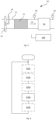
- FIG. 1 schematically illustrates a side view of an example of a vehicle 1.
- the vehicle 1 comprises a powertrain 2 comprising an internal combustion engine 3 and a gearbox 4.
- the gearbox 4 is connected to the driving wheels 7 of the vehicle 1 via a propeller shaft 6.
- the vehicle 1 further comprises an exhaust system 10 connected to the combustion engine 3.
- the exhaust system 10 is configured to treat the exhaust gas leaving the combustion engine 3.
- the vehicle 1 may optionally be a hybrid vehicle, in which case the vehicle comprises an electrical machine (not shown) in addition to the combustion engine 3.
- the vehicle 1 may be a heavy vehicle, such as a bus or a truck.
- FIG. 2 schematically illustrates one exemplifying embodiment of an exhaust system 10.
- the herein described method for deriving engine-out NOx concentration may be used in or for the illustrated exhaust system 10.
- the exhaust system 10 is configured to treat exhaust gas generated by a combustion engine 3 of a vehicle, such as the vehicle 1 illustrated in Figure 1 , and may thus be connected to a combustion engine 3.
- the combustion engine 3 is not a part of the exhaust system 10 per se and is therefore illustrated by a dashed box in the figure.
- optional features of the exhaust system 10 are illustrated by dashed boxes or lines.
- the exhaust system comprises a conduit 11 through which the exhaust gas flows when passing through the exhaust system 10.
- the direction of flow of exhaust gas through the exhaust system 10 is illustrated by the arrow 12.
- the exhaust system 10 comprises a first selective catalytic reduction, SCR, catalyst 16.
- the first SCR catalyst 16 may be the very first catalyst of the exhaust system 10, which means that it is the first catalyst that the exhaust gas from the combustion engine 3 reaches within the exhaust system 10.
- the first SCR catalyst 16 is configured to convert NOx into N 2 and water, and thereby reduce the NOx concentration in the exhaust gas.
- a reducing agent is injected into the exhaust gas upstream of the SCR.
- the reducing agent may typically be an aqueous ammonia or urea solution.
- the exhaust system 10 may further comprise an ammonia slip catalyst 20 arranged downstream of the first SCR 16.
- an ammonia slip catalyst may be configured to treat any excess ammonia not consumed in the first SCR 16.
- the exhaust system 10 comprises a first NOx sensor 18 arranged upstream of the first SCR 16.
- the first NOx sensor 18 is arranged downstream of the position where a reductant is introduced into the exhaust gas stream by means of the first dosing device 14.
- the exhaust system 10 further comprises a second NOx sensor 19 arranged downstream of the first SCR 16.
- the exhaust system 10 may, if desired, further comprise a second selective catalytic reduction catalyst 24 arranged downstream of the first selective catalytic reduction catalyst 16.
- the exhaust system 10 may also comprise a second dosing device 22 configured to introduce a reducing agent into the exhaust gas stream upstream of the second SCR 24.
- the second dosing device 22 may be arranged downstream of the first SCR 16.
- the second dosing device 22 may also be arranged downstream of the second NOx sensor 19 as illustrated in the figure.
- the exhaust system 10 may comprise further catalysts and/or filters.
- the exhaust system may further comprise a diesel particulate filter, DPF.
- DPF diesel particulate filter
- Such a DPF may suitably be a catalytic diesel particulate filter, cDPF.
- a DPF may for example be arranged downstream of the first SCR 16. If a second SCR 24 is present, the DPF may suitably be arranged upstream of the second SCR 24.
- FIG 3 schematically illustrates a part of another exemplifying embodiment of an exhaust system 10.
- the exhaust system 10 may have the same configuration as the exemplifying embodiment described above and shown in Figure 2 , except that the exhaust system 10 further comprises a turbocharger 13 and the first dosing device 14 is adapted to inject the reductant towards said turbocharger 13.
- the turbocharger 13 may suitably be a turbocharger associated with the combustion engine (such a combustion engine illustrated in Figure 2 ) whose exhaust gas the exhaust system 10 is configured to treat.
- Figure 3 further schematically illustrates an evaporation zone 15 formed by the conduit 11 downstream of the first dosing device 14.
- Said evaporation zone may suitably have a sufficient length for allowing essentially all of the reductant to be evaporated.
- the first NOx sensor may suitably be arranged downstream of said evaporation zone 15. In other words, the first NOx sensor is suitably arranged at a position in the exhaust system 10 where it is expected that the reductant is essentially fully evaporated.
- Figure 4 represents a flowchart schematically illustrating an exemplifying embodiment of the method for deriving engine-out NOx concentration according to the present disclosure. Optional features of the exemplifying embodiment of the method are illustrated by dashed boxes.
- the method may comprise a first step S101 of, while the dosing device is in operation so as to introduce reductant into an exhaust gas stream in the exhaust system, requesting a first concentration reading from the first NOx sensor.
- Step S101 may thus result in obtaining a first concentration reading from the first NOx sensor.
- the method may further comprise a second step S102 of requesting a second concentration reading from the second NOx sensor. Step S102 may thus result in obtaining a second concentration reading from the second NOx sensor.
- the method may further comprise a third step S103 of obtaining information of the amount of dosed reductant into the exhaust gas stream.
- Step 103 may further comprise converting the value of the dosed amount of reductant into a NOx equivalent.
- the method comprises a step S104 of deriving (more specifically calculating) engine-out NOx concentration based on a first concentration reading obtained from the first NOx sensor (e.g. resulting from step S101), a second concentration reading obtained from the second NOx sensor (e.g. resulting from step S102), and information regarding controlled amount of reductant introduced into the exhaust gas stream (e.g. resulting from step S103).
- the first concentration reading, used in step S104 is obtained from the first NOx sensor while the dosing device is in operation so as to introduce a controlled amount reductant into the exhaust gas stream, said controlled amount corresponding to the information regarding controlled amount of reductant introduced used when deriving engine-out NOx concentration.
- the method may further comprise a step S105 of storing the derived engine-out NOx concentration in a database or the like, optionally together with further information such as a time-stamp, information relating to a corresponding operation of a combustion engine connected to the exhaust system, and/or data regarding operating parameters of the exhaust system.
- the method may thereafter be returned to start so as to be repeated.
- the method may be ended, if desired.
- the method may be repeated as long as the exhaust system is in the normally intended operation and ended when the exhaust system is not in operation (e.g. when there is no exhaust gas flowing through the exhaust system).
- Such repeating of the method may also, if desired, be temporarily interrupted in situations where the exhaust system is not operated in the normally intended operation, for example due to regeneration of a constituent component thereof or due to failure diagnostics of a constituent component thereof.
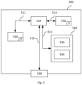
- FIG. 5 schematically illustrates an exemplifying embodiment of a device 500.
- the control device 100 described above may for example comprise the device 500, consist of the device 500, or be comprised in the device 500.
- the device 500 comprises a non-volatile memory 520, a data processing unit 510 and a read/write memory 550.
- the non-volatile memory 520 has a first memory element 530 in which a computer program, e.g. an operating system, is stored for controlling the function of the device 500.
- the device 500 further comprises a bus controller, a serial communication port, I/O means, an A/D converter, a time and date input and transfer unit, an event counter and an interruption controller (not depicted).
- the non-volatile memory 520 has also a second memory element 540.
- a computer program P that comprises instructions for deriving an engine-out NOx concentration of an exhaust gas stream in an exhaust system configured to treat exhaust gas from a combustion engine.
- Said exhaust system comprises a selective catalytic reduction catalyst, a dosing device adapted for injecting a reductant into the exhaust gas stream, a first NOx sensor arranged downstream of the dosing device but upstream of the selective catalytic reduction catalyst, and a second NOx sensor arranged downstream of the selective catalytic reduction catalyst.
- the computer program comprises instructions for deriving engine-out NOx concentration based on a first concentration reading obtained from the first NOx sensor and a second concentration reading obtained from the second NOx sensor, said first concentration reading being obtained while the dosing device is in operation so as to introduce reductant into the exhaust gas stream.
- the computer program may further comprise instructions for taking into account a controlled amount of reductant introduced into the exhaust gas stream via the dosing device when deriving engine-out NOx concentration based on the first concentration reading obtained from the first NOx sensor and the second concentration reading obtained from the second NOx sensor.
Landscapes
- Engineering & Computer Science (AREA)
- Chemical & Material Sciences (AREA)
- Chemical Kinetics & Catalysis (AREA)
- Combustion & Propulsion (AREA)
- Mechanical Engineering (AREA)
- General Engineering & Computer Science (AREA)
- Health & Medical Sciences (AREA)
- Toxicology (AREA)
- Exhaust Gas After Treatment (AREA)
Claims (10)
- Von einer Steuervorrichtung (100) ausgeführtes Verfahren zur Ableitung einer Motorausgangs-NOx-Konzentration eines Abgasstroms in einem Abgassystem (10), das zur Behandlung von Abgas aus einem Verbrennungsmotor (3) ausgebildet ist, wobei das Abgassystem (10) umfasst:einen selektiven katalytischen Reduktionskatalysator (16),eine Dosiervorrichtung (14), die zum Einspritzen eines Reduktionsmittels in den Abgasstrom eingerichtet ist,einen ersten NOx-Sensor (18), der stromabwärts der Dosiervorrichtung (14), aber stromaufwärts des selektiven katalytischen Reduktionskatalysators (16) angeordnet ist, undeinen zweiten NOx-Sensor (19), der stromabwärts des selektiven katalytischen Reduktionskatalysators (16) angeordnet ist;wobei das Verfahren folgenden Schritt umfasst:Ableiten (S104) einer Motorausgangs-NOx-Konzentration anhand eines von dem ersten NOx-Sensor (18) erhaltenen ersten Konzentrationsmesswerts und eines von dem zweiten NOx-Sensor (19) erhaltenen zweiten Konzentrationsmesswerts, wobei der erste Konzentrationsmesswert erhalten wird, während die Dosiervorrichtung (14) in Betrieb ist, um dem Abgasstrom Reduktionsmittel zuzuführen;dadurch gekennzeichnet, dass ein Turbolader (13) stromaufwärts des selektiven katalytischen Reduktionskatalysators (16) angeordnet ist, undwobei die Dosiervorrichtung (14) dazu eingerichtet ist, das Reduktionsmittel derart in Richtung des Turboladers (13) oder in den Turbolader (13) einzuspritzen, dass das Reduktionsmittel in dem Abgasstrom unter Nutzung einer Rotationsbewegung einer Turbine des Turboladers (13) verteilt wird, undwobei der erste Konzentrationsmesswert von dem ersten NOx-Sensor (18) zu einem ersten Zeitpunkt erhalten wird und
der zweite Konzentrationsmesswert von dem zweiten NOx-Sensor (19) zu einem zweiten Zeitpunkt erhalten wird undwobei der zweite Zeitpunkt nach einer Zeit liegt, die einer geschätzten Zeit für den Weg des Abgasstroms von dem ersten NOx-Sensor (18) zu dem zweiten NOx-Sensor (19) entspricht, die seit dem ersten Zeitpunkt verstrichen ist. - Verfahren nach Anspruch 1,
wobei der erste NOx-Sensor (18) an einer Stelle in dem Abgassystem angeordnet ist, an der die Verdampfung des Reduktionsmittels erwartet wird. - Verfahren nach einem der vorangehenden Ansprüche, wobei der Schritt des Ableitens einer Motorausgangs-NOx-Konzentration anhand des ersten Konzentrationsmesswerts und des zweiten Konzentrationsmesswerts erfolgt, indem auch eine gesteuerte Menge an Reduktionsmittel berücksichtigt wird, die dem Abgasstrom über die Dosiervorrichtung (14) zugeführt wird.
- Verfahren nach einem der vorangehenden Ansprüche, wobei der Schritt des Ableitens einer Motorausgangs-NOx-Konzentration anhand des ersten Konzentrationsmesswerts und des zweiten Konzentrationsmesswerts unter Berücksichtigung einer vorbestimmten Konstante erfolgt, die die Empfindlichkeit des ersten NOx-Sensors (18) gegenüber dem Reduktionsmittel darstellt.
- Verfahren nach einem der vorangehenden Ansprüche, wobei das Abgassystem (10) ferner einen Ammoniak-Schlupfkatalysator (20) umfasst, der stromabwärts des selektiven katalytischen Reduktionskatalysators (16), aber stromaufwärts des zweiten NOx-Sensors (19) angeordnet ist.
- Computerprogramm mit Befehlen, die, wenn sie von einem Abgassystem (10) nach Anspruch 8 ausgeführt werden, das Abgassystem dazu veranlassen, das Verfahren nach einem der Ansprüche 1 bis 5 auszuführen.
- Computerlesbares Medium mit Befehlen, die, wenn sie von einem Abgassystem (10) nach Anspruch 8 ausgeführt werden, das Abgassystem dazu veranlassen, das Verfahren nach einem der Ansprüche 1 bis 5 auszuführen.
- Abgassystem (10), das zur Behandlung von Abgas aus einem Verbrennungsmotor (3) ausgebildet ist, wobei das Abgassystem (10) umfasst:einen selektiven katalytischen Reduktionskatalysator (16),eine Dosiervorrichtung (14), die zum Einspritzen eines Reduktionsmittels in den Abgasstrom eingerichtet ist,einen ersten NOx-Sensor (18), der stromabwärts der Dosiervorrichtung (14), aber stromaufwärts des selektiven katalytischen Reduktionskatalysators (16) angeordnet ist,einen zweiten NOx-Sensor (19), der stromabwärts des selektiven katalytischen Reduktionskatalysators (16) angeordnet ist, undeine Steuervorrichtung (100), die zur Ableitung einer Motorausgangs-NOx-Konzentration eines Abgasstroms in einem Abgassystem (10) ausgebildet ist, das zur Behandlung von Abgas aus einem Verbrennungsmotor (3) ausgebildet ist,wobei das Abgassystem (10) ferner einen Turbolader (13) umfasst, der stromaufwärts des selektiven katalytischen Reduktionskatalysators (16) angeordnet ist, undwobei die Dosiervorrichtung (14) dazu eingerichtet ist, das Reduktionsmittel derart in Richtung des Turboladers (13) oder in den Turbolader (13) einzuspritzen, dass das Reduktionsmittel in dem Abgasstrom unter Nutzung einer Drehbewegung einer Turbine des Turboladers (13) verteilt wird,wobei die Steuervorrichtung (100) ausgebildet ist zum:
Ableiten einer Motorausgangs-NOx-Konzentration anhand eines von einem ersten NOx-Sensor (18) erhaltenen ersten Konzentrationsmesswerts und eines von einem zweiten NOx-Sensor (19) erhaltenen zweiten Konzentrationsmesswerts, wobei der erste Konzentrationsmesswert erhalten wird, während eine Dosiervorrichtung (14) in Betrieb ist, um dem Abgasstrom Reduktionsmittel zuzuführen, wobei der erste Konzentrationsmesswert von dem ersten NOx-Sensor (18) zu einem ersten Zeitpunkt erhalten wird und der zweite Konzentrationsmesswert von dem zweiten NOx-Sensor (19) zu einem zweiten Zeitpunkt erhalten wird undwobei der zweite Zeitpunkt nach einer Zeit liegt, die einer geschätzten Zeit für den Weg des Abgasstroms von dem ersten NOx-Sensor (18) zu dem zweiten NOx-Sensor (19) entspricht, die seit dem ersten Zeitpunkt verstrichen ist. - Abgassystem (10) nach Anspruch 8, das ferner dazu ausgebildet ist, eine gesteuerte Menge an Reduktionsmittel zu berücksichtigen, die dem Abgasstrom über die Dosiervorrichtung (14) zugeführt wird, wenn die Motorausgangs-NOx-Konzentration anhand des von dem ersten NOx-Sensor (18) erhaltenen ersten Konzentrationsmesswerts und des von dem zweiten NOx-Sensor (19) erhaltenen zweiten Konzentrationsmesswerts abgeleitet wird.
- Fahrzeug (1) mit dem Abgassystem (10) nach Anspruch 8 oder 9.
Priority Applications (4)
| Application Number | Priority Date | Filing Date | Title |
|---|---|---|---|
| EP21209443.7A EP4183987B1 (de) | 2021-11-22 | 2021-11-22 | Abgassystem und verfahren zur ableitung der nox-konzentration am motorausgang |
| CN202280074611.3A CN118215782A (zh) | 2021-11-22 | 2022-11-18 | 用于导出发动机排出的NOx浓度的控制装置和方法 |
| PCT/SE2022/051075 WO2023091071A1 (en) | 2021-11-22 | 2022-11-18 | CONTROL DEVICE AND METHOD FOR DERIVING ENGINE-OUT NOx CONCENTRATION |
| US18/710,232 US12392269B2 (en) | 2021-11-22 | 2022-11-18 | Control device and method for deriving engine-out NOx concentration |
Applications Claiming Priority (1)
| Application Number | Priority Date | Filing Date | Title |
|---|---|---|---|
| EP21209443.7A EP4183987B1 (de) | 2021-11-22 | 2021-11-22 | Abgassystem und verfahren zur ableitung der nox-konzentration am motorausgang |
Publications (2)
| Publication Number | Publication Date |
|---|---|
| EP4183987A1 EP4183987A1 (de) | 2023-05-24 |
| EP4183987B1 true EP4183987B1 (de) | 2025-03-26 |
Family
ID=78725255
Family Applications (1)
| Application Number | Title | Priority Date | Filing Date |
|---|---|---|---|
| EP21209443.7A Active EP4183987B1 (de) | 2021-11-22 | 2021-11-22 | Abgassystem und verfahren zur ableitung der nox-konzentration am motorausgang |
Country Status (4)
| Country | Link |
|---|---|
| US (1) | US12392269B2 (de) |
| EP (1) | EP4183987B1 (de) |
| CN (1) | CN118215782A (de) |
| WO (1) | WO2023091071A1 (de) |
Family Cites Families (12)
| Publication number | Priority date | Publication date | Assignee | Title |
|---|---|---|---|---|
| CN102792140B (zh) * | 2009-12-16 | 2016-01-20 | 康明斯过滤Ip公司 | 诊断NOx传感器的装置和方法 |
| WO2012151442A1 (en) * | 2011-05-03 | 2012-11-08 | Cummins Inc. | Control techniques for an scr aftertreatment system |
| US8607625B2 (en) | 2012-05-10 | 2013-12-17 | GM Global Technology Operations LLC | Service test for exhaust gas treatment system |
| WO2014070248A1 (en) * | 2012-11-05 | 2014-05-08 | International Engine Intellectual Property Company, Llc | Exhaust system after-treatment |
| US9388728B2 (en) | 2013-06-10 | 2016-07-12 | Cummins Emission Solutions, Inc. | Systems and methods for NOx sensor diagnostics |
| US9010087B1 (en) | 2013-11-13 | 2015-04-21 | Ford Global Technologies, Llc | Method and system for NOx sensor degradation |
| US9441519B2 (en) * | 2014-06-11 | 2016-09-13 | Cummins Inc. | System variation adaption for feed-forward controller |
| SE542040C2 (en) | 2016-10-26 | 2020-02-18 | Scania Cv Ab | An exhaust additive distribution device attached to a turbocharger turbine and an exhaust additive dosing system including such a distribution device |
| US10018092B2 (en) * | 2016-11-23 | 2018-07-10 | GM Global Technology Operations LLC | Model predictive control for multi-can selective catalytic reduction system |
| EP3615775B1 (de) | 2017-04-28 | 2021-03-10 | Wärtsilä Finland Oy | Verfahren zur steuerung der reduktionsmittelzufuhr und abgassystem |
| JP6731893B2 (ja) * | 2017-07-31 | 2020-07-29 | ヤンマーパワーテクノロジー株式会社 | 作業車両 |
| GB2602098A (en) * | 2020-12-17 | 2022-06-22 | Cummins Ltd | Turbine |
-
2021
- 2021-11-22 EP EP21209443.7A patent/EP4183987B1/de active Active
-
2022
- 2022-11-18 CN CN202280074611.3A patent/CN118215782A/zh active Pending
- 2022-11-18 WO PCT/SE2022/051075 patent/WO2023091071A1/en not_active Ceased
- 2022-11-18 US US18/710,232 patent/US12392269B2/en active Active
Also Published As
| Publication number | Publication date |
|---|---|
| WO2023091071A1 (en) | 2023-05-25 |
| EP4183987A1 (de) | 2023-05-24 |
| US12392269B2 (en) | 2025-08-19 |
| US20250035024A1 (en) | 2025-01-30 |
| CN118215782A (zh) | 2024-06-18 |
Similar Documents
| Publication | Publication Date | Title |
|---|---|---|
| US8596045B2 (en) | On-board-diagnosis method for an exhaust aftertreatment system and on-board-diagnosis system for an exhaust aftertreatment system | |
| US10161845B2 (en) | Method for monitoring a particulate filter | |
| CN105308282B (zh) | 用于诊断机动车辆的选择性催化还原系统的系统和方法 | |
| US11608766B2 (en) | Ammonia storage capacity of SCR catalyst unit | |
| US11927126B2 (en) | Methods for evaluating diesel exhaust fluid quality | |
| US20130138291A1 (en) | Regeneration diagnostic methods and systems | |
| CN109931129B (zh) | 用于监测内燃机的排气后处理系统的方法和装置 | |
| KR20160066817A (ko) | Scr 시스템의 고장진단방법 및 고장진단장치 | |
| US8682595B2 (en) | Method to estimate NO2 concentration in an exhaust gas of an internal combustion engine | |
| CN113530644B (zh) | 柴油机自适应式氮氧化物控制方法及装置 | |
| CN120265865A (zh) | 包括氢内燃发动机和后处理系统的系统 | |
| EP3943729A1 (de) | Verfahren zur diagnose und zum betrieb eines abgasnachbehandlungssystems | |
| US11408319B2 (en) | Method and internal combustion engine for improving the efficiency of an SCR system | |
| EP4183987B1 (de) | Abgassystem und verfahren zur ableitung der nox-konzentration am motorausgang | |
| RU2604656C2 (ru) | Оптимизированное управление катализатором (scr) селективного каталитического восстановления посредством периодической регенерации фильтра-улавливателя частиц | |
| EP4155511B1 (de) | System und verfahren zur überwachung eines abgasnachbehandlungssystems | |
| EP4187066B1 (de) | Verfahren und system zur sensoranalyse in einem abgasnachbehandlungssystem | |
| EP3784885B1 (de) | Verfahren und steuersystem zur steuerung der dosierung eines reduktionsmittels | |
| CN114667386B (zh) | 用于诊断排气流中物质的氧化的方法和系统 | |
| Subramanian et al. | Exhaust Volume Flow based Time Alignment in NO x Measurements in NOx Reduction Systems |
Legal Events
| Date | Code | Title | Description |
|---|---|---|---|
| PUAI | Public reference made under article 153(3) epc to a published international application that has entered the european phase |
Free format text: ORIGINAL CODE: 0009012 |
|
| STAA | Information on the status of an ep patent application or granted ep patent |
Free format text: STATUS: THE APPLICATION HAS BEEN PUBLISHED |
|
| AK | Designated contracting states |
Kind code of ref document: A1 Designated state(s): AL AT BE BG CH CY CZ DE DK EE ES FI FR GB GR HR HU IE IS IT LI LT LU LV MC MK MT NL NO PL PT RO RS SE SI SK SM TR |
|
| STAA | Information on the status of an ep patent application or granted ep patent |
Free format text: STATUS: REQUEST FOR EXAMINATION WAS MADE |
|
| 17P | Request for examination filed |
Effective date: 20231124 |
|
| RBV | Designated contracting states (corrected) |
Designated state(s): AL AT BE BG CH CY CZ DE DK EE ES FI FR GB GR HR HU IE IS IT LI LT LU LV MC MK MT NL NO PL PT RO RS SE SI SK SM TR |
|
| GRAP | Despatch of communication of intention to grant a patent |
Free format text: ORIGINAL CODE: EPIDOSNIGR1 |
|
| STAA | Information on the status of an ep patent application or granted ep patent |
Free format text: STATUS: GRANT OF PATENT IS INTENDED |
|
| INTG | Intention to grant announced |
Effective date: 20241017 |
|
| GRAS | Grant fee paid |
Free format text: ORIGINAL CODE: EPIDOSNIGR3 |
|
| GRAA | (expected) grant |
Free format text: ORIGINAL CODE: 0009210 |
|
| STAA | Information on the status of an ep patent application or granted ep patent |
Free format text: STATUS: THE PATENT HAS BEEN GRANTED |
|
| AK | Designated contracting states |
Kind code of ref document: B1 Designated state(s): AL AT BE BG CH CY CZ DE DK EE ES FI FR GB GR HR HU IE IS IT LI LT LU LV MC MK MT NL NO PL PT RO RS SE SI SK SM TR |
|
| REG | Reference to a national code |
Ref country code: GB Ref legal event code: FG4D |
|
| REG | Reference to a national code |
Ref country code: CH Ref legal event code: EP |
|
| REG | Reference to a national code |
Ref country code: DE Ref legal event code: R096 Ref document number: 602021028074 Country of ref document: DE |
|
| REG | Reference to a national code |
Ref country code: IE Ref legal event code: FG4D |
|
| REG | Reference to a national code |
Ref country code: SE Ref legal event code: TRGR |
|
| PG25 | Lapsed in a contracting state [announced via postgrant information from national office to epo] |
Ref country code: RS Free format text: LAPSE BECAUSE OF FAILURE TO SUBMIT A TRANSLATION OF THE DESCRIPTION OR TO PAY THE FEE WITHIN THE PRESCRIBED TIME-LIMIT Effective date: 20250626 |
|
| PG25 | Lapsed in a contracting state [announced via postgrant information from national office to epo] |
Ref country code: FI Free format text: LAPSE BECAUSE OF FAILURE TO SUBMIT A TRANSLATION OF THE DESCRIPTION OR TO PAY THE FEE WITHIN THE PRESCRIBED TIME-LIMIT Effective date: 20250326 |
|
| REG | Reference to a national code |
Ref country code: LT Ref legal event code: MG9D |
|
| PG25 | Lapsed in a contracting state [announced via postgrant information from national office to epo] |
Ref country code: NO Free format text: LAPSE BECAUSE OF FAILURE TO SUBMIT A TRANSLATION OF THE DESCRIPTION OR TO PAY THE FEE WITHIN THE PRESCRIBED TIME-LIMIT Effective date: 20250626 |
|
| PG25 | Lapsed in a contracting state [announced via postgrant information from national office to epo] |
Ref country code: HR Free format text: LAPSE BECAUSE OF FAILURE TO SUBMIT A TRANSLATION OF THE DESCRIPTION OR TO PAY THE FEE WITHIN THE PRESCRIBED TIME-LIMIT Effective date: 20250326 |
|
| PG25 | Lapsed in a contracting state [announced via postgrant information from national office to epo] |
Ref country code: LV Free format text: LAPSE BECAUSE OF FAILURE TO SUBMIT A TRANSLATION OF THE DESCRIPTION OR TO PAY THE FEE WITHIN THE PRESCRIBED TIME-LIMIT Effective date: 20250326 |
|
| PG25 | Lapsed in a contracting state [announced via postgrant information from national office to epo] |
Ref country code: BG Free format text: LAPSE BECAUSE OF FAILURE TO SUBMIT A TRANSLATION OF THE DESCRIPTION OR TO PAY THE FEE WITHIN THE PRESCRIBED TIME-LIMIT Effective date: 20250326 Ref country code: GR Free format text: LAPSE BECAUSE OF FAILURE TO SUBMIT A TRANSLATION OF THE DESCRIPTION OR TO PAY THE FEE WITHIN THE PRESCRIBED TIME-LIMIT Effective date: 20250627 |
|
| REG | Reference to a national code |
Ref country code: NL Ref legal event code: MP Effective date: 20250326 |
|
| PG25 | Lapsed in a contracting state [announced via postgrant information from national office to epo] |
Ref country code: NL Free format text: LAPSE BECAUSE OF FAILURE TO SUBMIT A TRANSLATION OF THE DESCRIPTION OR TO PAY THE FEE WITHIN THE PRESCRIBED TIME-LIMIT Effective date: 20250326 |
|
| REG | Reference to a national code |
Ref country code: AT Ref legal event code: MK05 Ref document number: 1779159 Country of ref document: AT Kind code of ref document: T Effective date: 20250326 |
|
| PG25 | Lapsed in a contracting state [announced via postgrant information from national office to epo] |
Ref country code: SM Free format text: LAPSE BECAUSE OF FAILURE TO SUBMIT A TRANSLATION OF THE DESCRIPTION OR TO PAY THE FEE WITHIN THE PRESCRIBED TIME-LIMIT Effective date: 20250326 |
|
| PG25 | Lapsed in a contracting state [announced via postgrant information from national office to epo] |
Ref country code: ES Free format text: LAPSE BECAUSE OF FAILURE TO SUBMIT A TRANSLATION OF THE DESCRIPTION OR TO PAY THE FEE WITHIN THE PRESCRIBED TIME-LIMIT Effective date: 20250326 Ref country code: PT Free format text: LAPSE BECAUSE OF FAILURE TO SUBMIT A TRANSLATION OF THE DESCRIPTION OR TO PAY THE FEE WITHIN THE PRESCRIBED TIME-LIMIT Effective date: 20250728 |
|
| PG25 | Lapsed in a contracting state [announced via postgrant information from national office to epo] |
Ref country code: IT Free format text: LAPSE BECAUSE OF FAILURE TO SUBMIT A TRANSLATION OF THE DESCRIPTION OR TO PAY THE FEE WITHIN THE PRESCRIBED TIME-LIMIT Effective date: 20250326 Ref country code: PL Free format text: LAPSE BECAUSE OF FAILURE TO SUBMIT A TRANSLATION OF THE DESCRIPTION OR TO PAY THE FEE WITHIN THE PRESCRIBED TIME-LIMIT Effective date: 20250326 |
|
| PG25 | Lapsed in a contracting state [announced via postgrant information from national office to epo] |
Ref country code: AT Free format text: LAPSE BECAUSE OF FAILURE TO SUBMIT A TRANSLATION OF THE DESCRIPTION OR TO PAY THE FEE WITHIN THE PRESCRIBED TIME-LIMIT Effective date: 20250326 |
|
| PG25 | Lapsed in a contracting state [announced via postgrant information from national office to epo] |
Ref country code: EE Free format text: LAPSE BECAUSE OF FAILURE TO SUBMIT A TRANSLATION OF THE DESCRIPTION OR TO PAY THE FEE WITHIN THE PRESCRIBED TIME-LIMIT Effective date: 20250326 |
|
| PG25 | Lapsed in a contracting state [announced via postgrant information from national office to epo] |
Ref country code: RO Free format text: LAPSE BECAUSE OF FAILURE TO SUBMIT A TRANSLATION OF THE DESCRIPTION OR TO PAY THE FEE WITHIN THE PRESCRIBED TIME-LIMIT Effective date: 20250326 |
|
| PG25 | Lapsed in a contracting state [announced via postgrant information from national office to epo] |
Ref country code: SK Free format text: LAPSE BECAUSE OF FAILURE TO SUBMIT A TRANSLATION OF THE DESCRIPTION OR TO PAY THE FEE WITHIN THE PRESCRIBED TIME-LIMIT Effective date: 20250326 |
|
| PG25 | Lapsed in a contracting state [announced via postgrant information from national office to epo] |
Ref country code: IS Free format text: LAPSE BECAUSE OF FAILURE TO SUBMIT A TRANSLATION OF THE DESCRIPTION OR TO PAY THE FEE WITHIN THE PRESCRIBED TIME-LIMIT Effective date: 20250726 |
|
| REG | Reference to a national code |
Ref country code: DE Ref legal event code: R097 Ref document number: 602021028074 Country of ref document: DE |
|
| PG25 | Lapsed in a contracting state [announced via postgrant information from national office to epo] |
Ref country code: DK Free format text: LAPSE BECAUSE OF FAILURE TO SUBMIT A TRANSLATION OF THE DESCRIPTION OR TO PAY THE FEE WITHIN THE PRESCRIBED TIME-LIMIT Effective date: 20250326 |
|
| PG25 | Lapsed in a contracting state [announced via postgrant information from national office to epo] |
Ref country code: CZ Free format text: LAPSE BECAUSE OF FAILURE TO SUBMIT A TRANSLATION OF THE DESCRIPTION OR TO PAY THE FEE WITHIN THE PRESCRIBED TIME-LIMIT Effective date: 20250326 |
|
| PLBE | No opposition filed within time limit |
Free format text: ORIGINAL CODE: 0009261 |
|
| STAA | Information on the status of an ep patent application or granted ep patent |
Free format text: STATUS: NO OPPOSITION FILED WITHIN TIME LIMIT |
|
| REG | Reference to a national code |
Ref country code: CH Ref legal event code: L10 Free format text: ST27 STATUS EVENT CODE: U-0-0-L10-L00 (AS PROVIDED BY THE NATIONAL OFFICE) Effective date: 20260211 |
|
| 26N | No opposition filed |
Effective date: 20260105 |
|
| PGFP | Annual fee paid to national office [announced via postgrant information from national office to epo] |
Ref country code: SE Payment date: 20260112 Year of fee payment: 5 |
|
| PGFP | Annual fee paid to national office [announced via postgrant information from national office to epo] |
Ref country code: GB Payment date: 20260119 Year of fee payment: 5 |
|
| PGFP | Annual fee paid to national office [announced via postgrant information from national office to epo] |
Ref country code: DE Payment date: 20260114 Year of fee payment: 5 |
|
| PGFP | Annual fee paid to national office [announced via postgrant information from national office to epo] |
Ref country code: BE Payment date: 20260113 Year of fee payment: 5 |
|
| PGFP | Annual fee paid to national office [announced via postgrant information from national office to epo] |
Ref country code: FR Payment date: 20260121 Year of fee payment: 5 |