EP4183635A1 - Élément structurel de véhicule - Google Patents
Élément structurel de véhicule Download PDFInfo
- Publication number
- EP4183635A1 EP4183635A1 EP21855957.3A EP21855957A EP4183635A1 EP 4183635 A1 EP4183635 A1 EP 4183635A1 EP 21855957 A EP21855957 A EP 21855957A EP 4183635 A1 EP4183635 A1 EP 4183635A1
- Authority
- EP
- European Patent Office
- Prior art keywords
- structural member
- flanges
- vehicle structural
- top wall
- lateral walls
- Prior art date
- Legal status (The legal status is an assumption and is not a legal conclusion. Google has not performed a legal analysis and makes no representation as to the accuracy of the status listed.)
- Pending
Links
- 238000005452 bending Methods 0.000 claims abstract description 40
- 230000002787 reinforcement Effects 0.000 claims description 54
- 239000011324 bead Substances 0.000 claims description 18
- 238000013001 point bending Methods 0.000 description 10
- 238000010586 diagram Methods 0.000 description 6
- 238000000034 method Methods 0.000 description 6
- 238000011156 evaluation Methods 0.000 description 4
- 238000006243 chemical reaction Methods 0.000 description 3
- 238000005094 computer simulation Methods 0.000 description 3
- 239000000463 material Substances 0.000 description 2
- 230000004048 modification Effects 0.000 description 2
- 238000012986 modification Methods 0.000 description 2
- 230000008569 process Effects 0.000 description 2
- 230000009467 reduction Effects 0.000 description 2
- 229910000831 Steel Inorganic materials 0.000 description 1
- 230000009471 action Effects 0.000 description 1
- 230000008859 change Effects 0.000 description 1
- 230000007423 decrease Effects 0.000 description 1
- 239000000446 fuel Substances 0.000 description 1
- 238000000926 separation method Methods 0.000 description 1
- 239000007787 solid Substances 0.000 description 1
- 239000010959 steel Substances 0.000 description 1
- 238000006467 substitution reaction Methods 0.000 description 1
Images


Classifications
-
- B—PERFORMING OPERATIONS; TRANSPORTING
- B60—VEHICLES IN GENERAL
- B60R—VEHICLES, VEHICLE FITTINGS, OR VEHICLE PARTS, NOT OTHERWISE PROVIDED FOR
- B60R19/00—Wheel guards; Radiator guards, e.g. grilles; Obstruction removers; Fittings damping bouncing force in collisions
- B60R19/02—Bumpers, i.e. impact receiving or absorbing members for protecting vehicles or fending off blows from other vehicles or objects
- B60R19/18—Bumpers, i.e. impact receiving or absorbing members for protecting vehicles or fending off blows from other vehicles or objects characterised by the cross-section; Means within the bumper to absorb impact
-
- B—PERFORMING OPERATIONS; TRANSPORTING
- B60—VEHICLES IN GENERAL
- B60J—WINDOWS, WINDSCREENS, NON-FIXED ROOFS, DOORS, OR SIMILAR DEVICES FOR VEHICLES; REMOVABLE EXTERNAL PROTECTIVE COVERINGS SPECIALLY ADAPTED FOR VEHICLES
- B60J5/00—Doors
- B60J5/04—Doors arranged at the vehicle sides
- B60J5/042—Reinforcement elements
- B60J5/0422—Elongated type elements, e.g. beams, cables, belts or wires
- B60J5/0438—Elongated type elements, e.g. beams, cables, belts or wires characterised by the type of elongated elements
- B60J5/0443—Beams
- B60J5/0444—Beams characterised by a special cross section
-
- B—PERFORMING OPERATIONS; TRANSPORTING
- B60—VEHICLES IN GENERAL
- B60R—VEHICLES, VEHICLE FITTINGS, OR VEHICLE PARTS, NOT OTHERWISE PROVIDED FOR
- B60R19/00—Wheel guards; Radiator guards, e.g. grilles; Obstruction removers; Fittings damping bouncing force in collisions
- B60R19/02—Bumpers, i.e. impact receiving or absorbing members for protecting vehicles or fending off blows from other vehicles or objects
- B60R19/18—Bumpers, i.e. impact receiving or absorbing members for protecting vehicles or fending off blows from other vehicles or objects characterised by the cross-section; Means within the bumper to absorb impact
- B60R2019/1806—Structural beams therefor, e.g. shock-absorbing
-
- B—PERFORMING OPERATIONS; TRANSPORTING
- B62—LAND VEHICLES FOR TRAVELLING OTHERWISE THAN ON RAILS
- B62D—MOTOR VEHICLES; TRAILERS
- B62D25/00—Superstructure or monocoque structure sub-units; Parts or details thereof not otherwise provided for
- B62D25/02—Side panels
Definitions
- the present invention relates to a vehicle structural member, and, in particular, to a vehicle structural member suitable as a bumper reinforcement installed in a vehicle bumper device.
- An automobile or other vehicle includes various vehicle structural members.
- One of them is a structural member having a hat-shaped cross section perpendicular to its longitudinal direction.
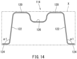
- Fig. 14 shows a conventional vehicle structural member 114 having a hat-shaped cross section.
- the vehicle structural member 114 generally includes a top wall 120, lateral walls 122, and flanges 124, and is usually press formed.
- Fig. 14 schematically shows the cross-sectional shape.
- the top wall 120 is drawn on the upper side in Fig. 14 .
- the left and right lateral walls 122 extend downward from the edges of the top wall 120 in a diverging manner.
- the left and right flanges 124 extend outwardly from the corresponding lower ends of the lateral walls 122 through L-shaped bends.
- the top wall 120 includes a concave bead 126.
- the hat-shaped cross section is provided with draft angles and no negative angles to ensure separation from the press die.
- the lateral walls 122 extends downward from the edges of the top wall 120.
- the flanges 124 extend parallel to the top wall 120.
- the bending angle ⁇ 1 between the lateral wall 122 and the flanges 124 is typically about 97°.
- the length of the flanges 124 from the lateral walls 122 is typically less than 11 mm. This is because the space allowed for arrangement of the vehicle structural member 114 is restricted to a relatively narrow space, as shown in Fig. 14 in the imaginary bounding box X of two-dot chain lines, by other structural members arranged around it.
- a typical example of such a vehicle structural member 114 is a bumper reinforcement 114 of a vehicle bumper device (see Japanese Patent Application Publications 2017-47818 and 2008-542094 ). Since the bumper reinforcement 114 of the vehicle bumper device is a structural member that receives an impact load in the event of a vehicle collision, it requires bending strength.
- the bending strength of the bumper reinforcement 114 which is a vehicle structural member, is generally evaluated by the three-point bending method.
- Figs. 12 and 13 show how the evaluation by the three-point bending method is performed.
- Fig. 12 shows the bumper reinforcement 114 before a load is applied, while Fig. 13 shows the same after the load is applied.
- the elongated bumper reinforcement 114 is supported by supporting members 118 placed at the positions where the bumper reinforcement 114 would be supported in a vehicle (i.e. at the positions corresponding to the bumper support structures 18 (see Fig. 2 )).
- An impactor 150 is then allowed to collide with the bumper reinforcement 114 from above at its center, and the reaction force received by the impactor 150 during this process is measured.
- the spacing between the support members 118 is, for example, 1000 mm, and the speed of the impactor 150 is, for example, 10 km/h.
- the bumper reinforcement 114 subjected to the load from the impactor 150 bends downward.
- the bending strength of the bumper reinforcement 114 is evaluated by measuring the reaction force received by the impactor 150 during this deformation.
- results of such an analysis based on CAE are evaluated in a force-stroke diagram, such as shown in Fig. 11 .
- the force-stroke diagram plots the reaction force (kN) versus the downward stroke (mm) of the impactor 150.
- the force-stroke curve for the conventional bumper reinforcement 114 having the cross-sectional shape described above is shown in Fig. 11 as graph Y
- the space for the vehicle structural member of the bumper reinforcement is limited by other structural members arranged adj acent to it. It is therefore not desirable to increase the size of the cross section to improve the bending strength. Increasing the thickness of the structural member increases the weight of the vehicle, which is not desirable in consideration of fuel efficiency.
- One aspect is a press-formed vehicle structural member, comprising: a top wall; a pair of lateral walls extending from opposite edges of the top wall in a broadening manner; and a pair of flanges bending outwardly from edges of the lateral walls, wherein the vehicle structural member has a hat-shaped cross section perpendicular to a longitudinal direction of the vehicle structural member, wherein a bending angle between the lateral walls and the flanges is 87° to 94°.
- a press-formed vehicle structural member comprising: a top wall; a pair of lateral walls extending from opposite edges of the top wall in a broadening manner; and a pair of flanges bending outwardly from edges of the lateral walls, wherein the vehicle structural member has a hat-shaped cross section perpendicular to a longitudinal direction of the vehicle structural member, wherein a length of the flanges from the lateral wall is greater than 11 mm.
- a press-formed vehicle structural member comprising: a top wall; a pair of lateral walls extending from opposite edges of the top wall in a broadening manner; and a pair of flanges bending outwardly from edges of the lateral walls, wherein the vehicle structural member has a hat-shaped cross section perpendicular to a longitudinal direction of the vehicle structural member, wherein a bending angle between the lateral wall and the flanges is 87° to 94°, and wherein a length of the flanges from the lateral wall is greater than 11 mm.
- the top wall has a cross-sectional width gradually narrowing from longitudinal ends to a center of the vehicle structural member, and the flanges have a cross-sectional width gradually widening from the longitudinal ends to the center of the vehicle structural member.
- the vehicle structural member further comprises a concave bead formed in the top wall, wherein the cross-sectional width of the concave bead of the top wall and the cross-sectional width of the flange are varied in an inverse relationship along a longitudinal direction of the vehicle structural member.
- the vehicle structural member is a bumper reinforcement in a vehicle bumper device.
- the vehicle structural member is a bumper reinforcement installed in a bumper device of a automobile or other vehicle.
- directions such as left and right, up and down, and front and back in the following descriptions indicate the directions in the drawing to which reference is made.
- the feature on the right side is indicated by adding a letter R to the end of the reference numeral
- the feature on the left side is indicated by adding a letter L to the end of the reference numeral.
- a vehicle bumper device 10 including a bumper reinforcement 14, which is the vehicle structural member will be described.
- Fig. 1 shows the position of the bumper device 10 in an automobile.
- the bumper device 10 extends generally along the width direction of the vehicle body 12 in the front and rear of the vehicle body 12.
- the bumper device 10 includes an elongated bumper reinforcement 14, a bumper cover 16, and bumper support structures 18.
- the bumper reinforcement 14 is provided as a core member responsible for strength of the bumper device 10.
- the bumper cover 16 fully covers the bumper reinforcement 14.
- the bumper cover 16 is positioned at the outermost portion of the bumper device 10 and is designed in consideration of appearance.
- the bumper cover 16 is made of plastic, which is a suitable material for forming designed surfaces.
- the bumper support structures 18 are disposed between frame members of the vehicle body 12 (not shown in Fig. 1 but shown in Fig. 9 to be discussed later with reference numerals 36) and the bumper reinforcement 14, at the opposite ends of the bumper reinforcement 14 in the longitudinal direction (or the width direction of the vehicle body).
- the impact load received by the bumper reinforcement 14 is transferred by the bumper support structure 18 to the vehicle body 12 and then supported by the vehicle body 12.
- the bumper reinforcement 14 will be described as positioned in the front of the vehicle body 12 for illustrative purposes.
- Fig. 2 is a perspective view of the bumper reinforcement 14 and the bumper support structure 18 as seen obliquely from the rear left to show their relative positions.
- the bumper reinforcement 14 is formed to have a generally hat-shaped cross section.
- the hat-shaped cross section comprises a top wall 20, lateral walls 22, and flanges 24L, 24R, formed by press forming.
- the press forming comprises bending and/or drawing, as is well known.
- the hat-shaped cross section is therefore shaped without any negative draft angles in consideration of the press forming.
- the hat shape may be as shown in Fig. 3 .
- the hat-shaped cross section includes a top wall 20, left and right flanges 24L, 24R, and left and right lateral walls 22L, 22R extending between the top wall 20 and the flanges 24L, 24R, respectively.
- the lateral walls 22L, 22R extend downwardly from the opposite edges of the top wall 20.
- the left and right lateral walls 22L, 22R are more spaced apart as they go downward. For example, as shown in Fig. 3 , they form a trapezoidal shape that does not include any negative draft angles.
- the flanges 24L, 24R extend outwardly in the left-right direction from the lower edges of the associated lateral walls 22L, 22R.
- the left flange 24L is connected to the lower end of the left lateral wall 22L.
- the right flange 24R is connected to the right lateral wall 22R.
- a normal (i.e., non-tailored blank) steel sheet with a uniform thickness may be used for the bumper reinforcement 14.
- the top wall 20 may include an elongated concave bead 26 extending in the longitudinal direction and located at the center of the width of the top wall 20 in order to increase the strength of the top wall 20 in terms of the shape.
- the hat-shaped cross section is formed such that the bending angle ⁇ 2 between the lateral walls 22L, 22R and the flanges 24L, 24R is a right angle (90°).
- dashed lines at the flanges 24L, 24R indicate the flanges of the conventional structure described above drawn relative to the lateral walls 22L, 22R.
- the flanges 24L, 24R of the conventional structure are parallel to the top wall 20, indicated in the dashed lines in Fig. 3 , so that the bending angle ( ⁇ 1 in FIG. 14 ) with respect to the lateral walls 22L, 22R is about 97°.
- the flanges 24L, 24R are press formed with the bending angle ⁇ 2 being 87° to 94°.
- the bending angle ⁇ 2 can be, for example, 90° (a right angle), as shown in Fig. 3 .
- the flanges 24L, 24R are thus not parallel to the top wall 20.
- Fig. 4 shows how the bumper reinforcement 14 shown in Fig. 3 is deformed into a hat-shaped cross section when the bumper reinforcement 14 is subjected to three-point bending by computer simulation (see Figs. 12 and 13 ).
- an impact load F is applied to the center of the top wall 20
- the lateral walls 22L, 22R fall inward.
- the bending angle ⁇ 2 between the lateral walls 22L, 22R and the flanges 24L, 24R remains at the right angle during this inward fall, even when the lateral walls 22L, 22R become perpendicular to the top wall 20 as seen in Fig. 4 .
- the hat-shaped cross section can be formed such that the length of the flanges 24L, 24R is longer than 11 mm.
- the length of the flanges 24L, 24R is 21 mm, which is 10 mm longer than the conventional structure.
- the length of the flanges 24L, 24R is preferably longer than 11 mm and less than or equal to 30 mm.
- the hat-shaped cross section disposed within the box X drawn in the two-dot chain line in Fig. 5 . is formed short.
- a conventional hat-shaped cross section is shown in a dashed line.
- the reduction in the width of the top wall 20 in this embodiment is absorbed by the reduction of the width of the conventional concave bead 26 or the width of the top wall 20.
- the extended length, which is longer than 11 mm as described above, of the flanges 24L, 24R in the hat-shaped cross section results in a reduced movement of the edges of the flanges, which is likely to be displaced the most, when the hat-shaped cross section collapses inward under a load. This means the inward collapse of the lateral walls 22L, 22R is reduced and thus the bending strength is improved.
- the hat-shaped cross section may have a bending angle ⁇ 2 of 87° to 94° between the lateral walls 22L, 22R and the flanges 24L, 24R as well as the length of the flanges 24L, 24R is longer than 11 mm. That is, the hat-shaped cross section of this embodiment is a combination of the embodiments of Figs. 3 and 5 described above.
- the bending angle ⁇ 2 can be, for example, 90° (a right angle), but is not limited to this.
- Fig. 6 shows the hat-shaped cross section in a solid line together with a conventional hat-shaped cross section in a broken line, fitted within the box X. It can be clearly seen from the difference between the two hat-shaped cross sections shown in the solid and broken lines that in the present embodiment the bending angle ⁇ 2 between the lateral walls 22L, 22R and the flanges 24L, 24R is a right angle, and the length of the flanges 24L, 24R is longer than that of the conventional structure.
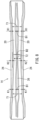
- Fig. 7 is a perspective view of the overall bumper reinforcement 14
- Fig. 8 is a plan view of the overall bumper reinforcement 14 as seen from the front.
- the top wall 20 and the flanges 24L, 24R of the bumper reinforcement 14 are gradually varied.
- the cross-sectional width of the top wall 20 is gradually narrowed from the longitudinal ends of the bumper reinforcement 14 to the center.
- Figs. 7 and 8 indicates the width of the top wall 20 as T1 at the ends and T2 at the center; the width gradually decreases from T1 to T2.
- Figs. 7 and 8 indicates the widths of the flanges 24L, 24R as K1 at their ends and K2 at their centers; the widths gradually increase from K1 to K2.
- the hat-shaped cross section can have the same shape as in the embodiments shown in Figs. 3 to 6 described above. That is, the bending angle ⁇ 2 between the lateral walls 22L, 22R and the flanges 24L, 24R may be between 87° to 94°, and/or the length of the flanges 24L, 24R may be, entirely or partly, longer than 11 mm.
- the top wall 20 includes a concave bead 26, and the cross-sectional width of the concave bead 26 and the cross-sectional width of the flanges 24L, 24R are varied in an inverse relationship along the longitudinal direction of the bumper reinforcement 14. That is, the width of the flanges 24L, 24R is wider in the regions where the width of the concave bead 26 is narrower. Conversely, the width of the flanges 24L, 24R is narrower in the regions where the width of the concave bead 26 is wider. Thereby, the hat-shaped cross sections of the bumper reinforcement 14 can be accommodated in a substantially uniform space over the longitudinal direction.
- the width B 1 of the concave bead 26 is wider, so that the width K1 of the flanges 24L, 24R is narrower.
- the width B2 of the concave bead 26 is narrower, so that the width K2 of the flanges 24L, 24R is wider.
- the cross-sectional size of the bumper reinforcement 14 does not increase anywhere along the longitudinal direction, and therefore the bumper reinforcement 14 can be accommodated in the space of a fixed size.
- the vehicle structural member in the above embodiments has been described as the bumper reinforcement 14 included in a bumper device 10 of an automobile or other vehicle.
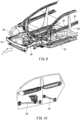
- the features of the bumper reinforcement 14 can also be applied to various vehicle structural members such as shown in Figs. 9 and 10 .
- it is applicable to a center pillar 28, a door belt line reinforcement 30, or a locker outer reinforcement 32 as shown in Fig. 9 , or a door side impact protection beam 34 as shown in Fig. 10 .
- the features of the embodiments described above can also be applied to a vehicle structural member formed from a tailored blank.
- the depth of the concave bead 26 formed in the top wall 20 has not been mentioned. In various embodiments, the depth may be uniform along the longitudinal direction, or alternatively the depth may vary along the longitudinal direction.
- the concave bead 26 has been arranged only at one place in the cross section.
- the top wall 20 may include one or more additional shallower beads.
- the bending angle between the lateral wall and the flanges of the vehicle structural member is a right angle.
- the length of the flanges of the vehicle structural member is longer than 11 mm. This length of the flanges, which is longer than that of conventional flanges, reduces the movement of the edges of the flanges, where the structural member is likely to displace most, when a load is applied to the top wall and thereby the vertical wall falls inward. This leads to an improved bending strength as compared to the conventional structure.
- the bending angle between the lateral wall and the flanges of the vehicle structural member is a right angle, as well as the length of the flanges is longer than 11 mm.
- the cross-sectional width of the top wall gradually narrows from the longitudinal ends to the center, and the cross-sectional width of the flanges gradually widens from the longitudinal ends to the center.
- the top wall includes a concave bead, and the cross-sectional width of the concave bead of the top wall and the cross-sectional width of the flanges are varied in an inverse relationship along the longitudinal direction of the vehicle structural member.
- the vehicle structural member is suitable for bumper reinforcement in a vehicle bumper system.
Applications Claiming Priority (2)
| Application Number | Priority Date | Filing Date | Title |
|---|---|---|---|
| JP2020135609A JP7358307B2 (ja) | 2020-08-11 | 2020-08-11 | 車両用構造部材 |
| PCT/JP2021/029507 WO2022034878A1 (fr) | 2020-08-11 | 2021-08-10 | Élément structurel de véhicule |
Publications (1)
| Publication Number | Publication Date |
|---|---|
| EP4183635A1 true EP4183635A1 (fr) | 2023-05-24 |
Family
ID=80247896
Family Applications (1)
| Application Number | Title | Priority Date | Filing Date |
|---|---|---|---|
| EP21855957.3A Pending EP4183635A1 (fr) | 2020-08-11 | 2021-08-10 | Élément structurel de véhicule |
Country Status (5)
| Country | Link |
|---|---|
| US (1) | US20230294625A1 (fr) |
| EP (1) | EP4183635A1 (fr) |
| JP (1) | JP7358307B2 (fr) |
| CN (1) | CN115803232A (fr) |
| WO (1) | WO2022034878A1 (fr) |
Family Cites Families (6)
| Publication number | Priority date | Publication date | Assignee | Title |
|---|---|---|---|---|
| SE0501173L (sv) | 2005-05-25 | 2006-04-04 | Gestamp Hardtech Ab | Stötfångarbalk |
| JP4330652B2 (ja) | 2007-03-28 | 2009-09-16 | ユニプレス株式会社 | 車両用金属製アブソーバ、車両用バンパシステム、自動車バンパ用アブソーバ及び自動車バンパシステム |
| JP6125466B2 (ja) | 2014-06-11 | 2017-05-10 | 豊田鉄工株式会社 | 自動車用構造部材 |
| JP2017007450A (ja) | 2015-06-19 | 2017-01-12 | 豊田鉄工株式会社 | バンパリインフォースメント構造 |
| JP6479612B2 (ja) | 2015-09-03 | 2019-03-06 | 豊田鉄工株式会社 | バンパリインフォースメントの製造法 |
| JP2018075956A (ja) | 2016-11-09 | 2018-05-17 | 豊田鉄工株式会社 | バンパリインフォースメント |
-
2020
- 2020-08-11 JP JP2020135609A patent/JP7358307B2/ja active Active
-
2021
- 2021-08-10 CN CN202180049387.8A patent/CN115803232A/zh active Pending
- 2021-08-10 US US18/041,404 patent/US20230294625A1/en active Pending
- 2021-08-10 EP EP21855957.3A patent/EP4183635A1/fr active Pending
- 2021-08-10 WO PCT/JP2021/029507 patent/WO2022034878A1/fr unknown
Also Published As
| Publication number | Publication date |
|---|---|
| WO2022034878A1 (fr) | 2022-02-17 |
| CN115803232A (zh) | 2023-03-14 |
| JP2022032110A (ja) | 2022-02-25 |
| JP7358307B2 (ja) | 2023-10-10 |
| US20230294625A1 (en) | 2023-09-21 |
Similar Documents
| Publication | Publication Date | Title |
|---|---|---|
| US10604092B2 (en) | Bumper beam structure | |
| EP3068678B1 (fr) | Poutres à section transversale en forme de u | |
| KR101143702B1 (ko) | 자동차용 범퍼 빔 | |
| KR101251385B1 (ko) | 범퍼 비임 | |
| JP5119477B2 (ja) | 耐座屈性に優れた車両用耐衝突補強材及びその製造方法 | |
| CN105905057B (zh) | 车辆用保险杠增强构造 | |
| RU2757795C1 (ru) | Брус буфера, имеющий стальное усиление | |
| JP2010042753A (ja) | バンパーリインフォースメントおよびその製造方法 | |
| EP3630551B1 (fr) | Renfort de pare-chocs à pièce de renfort | |
| KR20170010831A (ko) | 도어 임팩트 빔 | |
| KR20090064840A (ko) | 범퍼 시스템 | |
| EP4183635A1 (fr) | Élément structurel de véhicule | |
| KR102558628B1 (ko) | 차량용 구조 부재 | |
| CN111247015B (zh) | 机动车 | |
| US11400800B2 (en) | Structural member for automobiles | |
| JP6213314B2 (ja) | ドアインパクトビームおよびその製造法 | |
| EP3156287A1 (fr) | Élément structural pour automobile | |
| CN208036445U (zh) | 一种车辆门槛 | |
| US11718351B2 (en) | Automobile structural member and vehicle body | |
| JP7192837B2 (ja) | 車両用構造部材 | |
| EP3932750B1 (fr) | Élément structural pour véhicule | |
| JP7362411B2 (ja) | アブソーバ | |
| CN217672513U (zh) | 一种车辆碰撞导向机构及车辆 | |
| US20230271649A1 (en) | Structural member for automobile body | |
| WO2023140358A1 (fr) | Renfort de pare-chocs à section transversale ouverte |
Legal Events
| Date | Code | Title | Description |
|---|---|---|---|
| STAA | Information on the status of an ep patent application or granted ep patent |
Free format text: STATUS: THE INTERNATIONAL PUBLICATION HAS BEEN MADE |
|
| PUAI | Public reference made under article 153(3) epc to a published international application that has entered the european phase |
Free format text: ORIGINAL CODE: 0009012 |
|
| STAA | Information on the status of an ep patent application or granted ep patent |
Free format text: STATUS: REQUEST FOR EXAMINATION WAS MADE |
|
| 17P | Request for examination filed |
Effective date: 20230216 |
|
| AK | Designated contracting states |
Kind code of ref document: A1 Designated state(s): AL AT BE BG CH CY CZ DE DK EE ES FI FR GB GR HR HU IE IS IT LI LT LU LV MC MK MT NL NO PL PT RO RS SE SI SK SM TR |
|
| DAV | Request for validation of the european patent (deleted) | ||
| DAX | Request for extension of the european patent (deleted) |