EP4183519A1 - Fulcrum opening/closing type air chuck - Google Patents
Fulcrum opening/closing type air chuck Download PDFInfo
- Publication number
- EP4183519A1 EP4183519A1 EP22205443.9A EP22205443A EP4183519A1 EP 4183519 A1 EP4183519 A1 EP 4183519A1 EP 22205443 A EP22205443 A EP 22205443A EP 4183519 A1 EP4183519 A1 EP 4183519A1
- Authority
- EP
- European Patent Office
- Prior art keywords
- type air
- closing type
- porous body
- fingers
- air chuck
- Prior art date
- Legal status (The legal status is an assumption and is not a legal conclusion. Google has not performed a legal analysis and makes no representation as to the accuracy of the status listed.)
- Granted
Links
Images



Classifications
-
- B—PERFORMING OPERATIONS; TRANSPORTING
- B25—HAND TOOLS; PORTABLE POWER-DRIVEN TOOLS; MANIPULATORS
- B25J—MANIPULATORS; CHAMBERS PROVIDED WITH MANIPULATION DEVICES
- B25J15/00—Gripping heads and other end effectors
- B25J15/08—Gripping heads and other end effectors having finger members
-
- B—PERFORMING OPERATIONS; TRANSPORTING
- B25—HAND TOOLS; PORTABLE POWER-DRIVEN TOOLS; MANIPULATORS
- B25B—TOOLS OR BENCH DEVICES NOT OTHERWISE PROVIDED FOR, FOR FASTENING, CONNECTING, DISENGAGING, OR HOLDING
- B25B5/00—Clamps
- B25B5/06—Arrangements for positively actuating jaws
- B25B5/061—Arrangements for positively actuating jaws with fluid drive
- B25B5/064—Arrangements for positively actuating jaws with fluid drive with clamping means pivoting around an axis perpendicular to the pressing direction
-
- B—PERFORMING OPERATIONS; TRANSPORTING
- B25—HAND TOOLS; PORTABLE POWER-DRIVEN TOOLS; MANIPULATORS
- B25J—MANIPULATORS; CHAMBERS PROVIDED WITH MANIPULATION DEVICES
- B25J9/00—Program-controlled manipulators
- B25J9/10—Program-controlled manipulators characterised by positioning means for manipulator elements
- B25J9/14—Program-controlled manipulators characterised by positioning means for manipulator elements fluid
- B25J9/146—Rotary actuators
-
- B—PERFORMING OPERATIONS; TRANSPORTING
- B23—MACHINE TOOLS; METAL-WORKING NOT OTHERWISE PROVIDED FOR
- B23B—TURNING; BORING
- B23B31/00—Chucks; Expansion mandrels; Adaptations thereof for remote control
- B23B31/02—Chucks
- B23B31/10—Chucks characterised by the retaining or gripping devices or their immediate operating means
- B23B31/12—Chucks with simultaneously-acting jaws, whether or not also individually adjustable
- B23B31/18—Chucks with simultaneously-acting jaws, whether or not also individually adjustable pivotally movable in planes containing the axis of the chuck
-
- B—PERFORMING OPERATIONS; TRANSPORTING
- B25—HAND TOOLS; PORTABLE POWER-DRIVEN TOOLS; MANIPULATORS
- B25J—MANIPULATORS; CHAMBERS PROVIDED WITH MANIPULATION DEVICES
- B25J15/00—Gripping heads and other end effectors
- B25J15/02—Gripping heads and other end effectors servo-actuated
- B25J15/0206—Gripping heads and other end effectors servo-actuated comprising articulated grippers
-
- B—PERFORMING OPERATIONS; TRANSPORTING
- B25—HAND TOOLS; PORTABLE POWER-DRIVEN TOOLS; MANIPULATORS
- B25J—MANIPULATORS; CHAMBERS PROVIDED WITH MANIPULATION DEVICES
- B25J15/00—Gripping heads and other end effectors
- B25J15/02—Gripping heads and other end effectors servo-actuated
- B25J15/0206—Gripping heads and other end effectors servo-actuated comprising articulated grippers
- B25J15/0226—Gripping heads and other end effectors servo-actuated comprising articulated grippers actuated by cams
-
- B—PERFORMING OPERATIONS; TRANSPORTING
- B25—HAND TOOLS; PORTABLE POWER-DRIVEN TOOLS; MANIPULATORS
- B25J—MANIPULATORS; CHAMBERS PROVIDED WITH MANIPULATION DEVICES
- B25J19/00—Accessories fitted to manipulators, e.g. for monitoring, for viewing; Safety devices combined with or specially adapted for use in connection with manipulators
- B25J19/0058—Means for cleaning manipulators, e.g. dust removing means
-
- B—PERFORMING OPERATIONS; TRANSPORTING
- B25—HAND TOOLS; PORTABLE POWER-DRIVEN TOOLS; MANIPULATORS
- B25J—MANIPULATORS; CHAMBERS PROVIDED WITH MANIPULATION DEVICES
- B25J19/00—Accessories fitted to manipulators, e.g. for monitoring, for viewing; Safety devices combined with or specially adapted for use in connection with manipulators
- B25J19/0075—Means for protecting the manipulator from its environment or vice versa
-
- B—PERFORMING OPERATIONS; TRANSPORTING
- B23—MACHINE TOOLS; METAL-WORKING NOT OTHERWISE PROVIDED FOR
- B23B—TURNING; BORING
- B23B2270/00—Details of turning, boring or drilling machines, processes or tools not otherwise provided for
- B23B2270/02—Use of a particular power source
- B23B2270/027—Pneumatics
Definitions
- the present invention relates to a fulcrum opening/closing type air chuck including a pair of pivoting gripping members, and more particularly to a fulcrum opening/closing type air chuck having a dust-proof function.
- JP H10-080888 A discloses a chuck device in which a pair of gripping members pivotably supported on a body are driven by a cylinder mechanism.
- a cover member is attached to one end portion of a body to prevent dust from entering the interior of the body. Specifically, a first curved portion provided on the pivoting portion of each gripping member is brought into contact with the corner portion of the body, and a second curved portion provided on the pivoting portion of the gripping member is brought into contact with the recess of the cover member.
- a rubber dust cover covering the outer side of the gripping members may be attached to the body.
- the gripping members of the parallel opening/closing type air chuck in which the gripping members are slid have a large movable range. For this reason, in order to prevent the dust cover from coming into contact with the gripping members and being torn, a large dust cover is required, and the apparatus becomes large.
- a rubber sealing member such as a gasket may be disposed between the gripping members and the body.
- a rubber sealing member is used, the sliding resistance when the gripping members pivot becomes large.
- the present invention has the object of solving the aforementioned problems.
- the present invention is a fulcrum opening/closing type air chuck in which a pair of fingers are each supported so as to be pivotable about a pivot support shaft attached to a body, and a drive unit configured to drive the pair of fingers to move away from each other and approach each other is disposed inside the body.
- the fulcrum opening/closing type air chuck includes a porous body attached to the body and configured to come into contact with the fingers, and purge air passes through the porous body and is discharged to outside.
- the fulcrum opening/closing type air chuck according to the present invention is provided with the porous body that is attached to the body and comes into contact with the fingers, and the purge air passes through the porous body and is discharged to the outside. Therefore, dust can be prevented from entering the interior of the body without increasing the sliding resistance of the fingers.
- a fulcrum opening/closing type air chuck 10 includes a body 12, a pair of fingers 80, a drive unit 58, and first to third porous bodies 94, 96, and 110.
- the pair of fingers 80 are pivotably supported on the body 12.
- the drive unit 58 includes a piston 60 and a drive rod 70 integrally coupled to the piston 60, and is disposed inside the body 12.
- the pair of fingers 80 are driven to move away from each other and approach each other by the drive unit 58.
- the drive unit 58 when terms in relation to up and down directions are used, for the sake of convenience, such terms refer to the directions shown in FIG. 3 , however, the actual arrangement of the constituent members and the like is not necessarily limited to this feature.
- the body 12 includes a main body 14 and an end plate 48.
- the end plate 48 is attached to the upper end of the main body 14 by screw members 52.
- the main body 14 having a quadrangular prism shape includes a cylinder hole 16 therein, and the piston 60 is slidably disposed in the cylinder hole 16.
- the lower end of the cylinder hole 16 is closed by a cap 54.
- a cylinder chamber formed by the cylinder hole 16 is partitioned into a first pressure chamber 18 located above the piston 60, and a second pressure chamber 20 located below the piston 60.
- the main body 14 is provided with a first port 22 for supplying/discharging air to/from the first pressure chamber 18, and a second port 24 for supplying/discharging air to/from the second pressure chamber 20.
- the main body 14 is cut out parallel to wide side surfaces 30 from one of a pair of narrow side surfaces 34 to the other thereof above the cylinder hole 16. That is, the main body 14 includes a pair of side walls 28 above the cylinder hole 16.
- Reference numeral 47 denotes attachment holes for attaching the body 12 to a conveying device (not shown) or the like.
- a piston packing 62, magnets 64, and a wear ring 66 are mounted to the outer peripheral portion of the piston 60.
- the piston packing 62 provides a seal between the first pressure chamber 18 and the second pressure chamber 20.
- the wide side surfaces 30 of the main body 14 have sensor grooves 32.
- the magnetic flux of the magnets 64 can be detected by magnetic sensors (not shown) attached to the sensor grooves 32.
- a damper 68 is attached to the upper end of the piston 60. The damper 68 absorbs an impact when the piston 60 moves to an upper end position.
- the drive rod 70 is inserted into a bush 72 mounted to the cylinder hole 16, and is supported so as to be movable up and down.
- a rod packing 74 in sliding contact with the drive rod 70 is mounted to the upper end of the cylinder hole 16.
- the rod packing 74 airtightly holds the first pressure chamber 18.
- a sealing member 56 for keeping the second pressure chamber 20 airtight from the outside is mounted to the outer peripheral portion of the cap 54.
- the drive rod 70 extends upward from the cylinder hole 16.
- the upper end of drive rod 70 is provided with a pair of arm portions 76 directed toward the respective fingers 80.
- a cylindrical rolling element 78 is rotatably supported at the distal end of each arm portion 76.
- Each finger 80 is formed of a fan-shaped pivoting portion 82 and an elongated gripping portion 92.
- the pivoting portion 82 and the gripping portion 92 have a constant width W0.
- the pivoting portion 82 is disposed between the pair of side walls 28 of the main body 14.
- a pivot support shaft 40 is mounted across the pair of side walls 28 of the main body 14, and the pivot support shaft 40 is inserted into a bush 88 mounted to the center of the pivoting portion 82.
- the fingers 80 are supported so as to be pivotable about the pivot support shafts 40.
- the pivoting portions 82 each include a first curved surface 84 facing the end plate 48, and a second curved surface 86 facing a fitting recess 42 of the main body 14 described later.
- the first curved surface 84 and the second curved surface 86 each have a constant radius of curvature about the axis of the pivot support shaft 40.
- the radius of curvature of the first curved surface 84 is greater than the radius of curvature of the second curved surface 86.
- the pivoting portion 82 has two end surfaces facing the side walls 28 of the main body 14.
- the end surfaces of the pivoting portion 82 are perpendicular to the axis of the pivot support shaft 40.
- the gripping portions 92 each extend radially outward from one circumferential end portion of the first curved surface 84 of each of the pivoting portions 82.
- the pivoting portions 82 each include a groove portion 90 extending to a predetermined depth from another circumferential end portion of the first curved surface 84.
- the rolling elements 78 supported by the arm portions 76 of the drive rod 70 are disposed in the groove portions 90 of the pivoting portions 82, and can move in the groove portions 90 while rolling.
- the vertical linear motion of the drive rod 70 is converted into the pivot motion of the fingers 80.
- the pair of fingers 80 pivot in a direction in which the pair of gripping portions 92 move away from each other, and when the drive rod 70 moves downward, the pair of fingers 80 pivot in a direction in which the pair of gripping portions 92 approach each other.
- the end plate 48 includes, at both ends thereof, cutout portions 50 to be passages of the gripping portions 92 when the fingers 80 pivot.
- the narrow side surfaces 34 of the main body 14 each have an opening 36 that opens between the pair of side walls 28.
- the pivoting portions 82 of the fingers 80 and the first to third porous bodies 94, 96, and 110 prevent the interior of the body 12 from being directly connected to the outside through the openings 36 of the main body 14 and the cutout portions 50 of the end plate 48. That is, a purge air storage space 38 isolated from the outside is formed above the cylinder hole 16.
- the first to third porous bodies 94, 96, 110 are each formed of a lubricant retainer that is a fiber composite. However, the first to third porous bodies 94, 96, and 110 are not impregnated with a lubricant. The first to third porous bodies 94, 96, and 110 cannot prevent fine dust from entering the interior by themselves due to the nature of having voids therein. However, by performing air purging described later, it is possible to prevent fine dust from entering from the outside.
- the first to third porous bodies 94, 96, and 110 that come into contact with the fingers 80 have small deformation resistance and are easily deformed. Even if the first to third porous bodies 94, 96, and 110 are brought into contact with the fingers 80 at a predetermined pressure in order to reliably fill the gap between the first to third porous bodies 94, 96, and 110 and the fingers 80, resistance (sliding resistance) when the fingers 80 move is small.
- the first to third porous bodies 94, 96, and 110 are formed of lubricant retainers, but may be formed of felt or sponge.
- the first porous body 94 is formed in an elongated rectangular plate shape having a constant width W1.
- the first porous body 94 is attached to the lower surface of the end plate 48 using, for example, an adhesive.
- the width W1 of the first porous body 94 is equal to or slightly larger than the width W0 of the pivoting portions 82 of the fingers 80.
- the first curved surface 84 of the pivoting portion 82 of each of the fingers 80 comes into contact with the end portion of the first porous body 94 in the lengthwise direction (see FIG. 3 ).
- a portion of the first porous body 94 that comes into contact with the first curved surface 84 is deformed by being pressed by the first curved surface 84.
- the second porous body 96 includes an elongated plate-shaped base portion 98, and a pair of stepped portions 106 bent in an L-shape from both ends of the base portion 98.
- the base portion 98 is provided with, at the center thereof in the lengthwise direction, a first hole portion 100 through which the drive rod 70 is inserted. Further, the base portion 98 is provided with, at one end portion thereof in the lengthwise direction, a second hole portion 102 serving as a passage of purge air.
- the base portion 98 is provided with a pair of projecting portions 104 projecting from the vicinity of the first hole portion 100 to both sides.
- the inner diameter of the first hole portion 100 is smaller than the outer diameter of the drive rod 70. In other words, when the drive rod 70 is inserted into the first hole portion 100, the first hole portion 100 expands.
- the second porous body 96 is attached to the main body 14 so as to face the second curved surfaces 86 of the pivoting portions 82 of the fingers 80.
- the main body 14 includes the fitting recess 42 whose bottom surface is a surface where the upper end of the cylinder hole 16 is opened.
- the second porous body 96 including the stepped portions 106 is fitted into the fitting recess 42 of the main body 14.
- the main body 14 includes recessed grooves 44 on the inner sides of the pair of wide side surfaces 30, and the projecting portions 104 of the second porous body 96 are fitted into the recessed grooves 44 (see FIG. 4 ).
- the width W2 of the stepped portions 106 of the second porous body 96 is equal to or slightly larger than the width W0 of the pivoting portions 82 of the fingers 80.
- the second curved surfaces 86 of the pivoting portions 82 of the fingers 80 come into contact with corner portions 108 of the stepped portions 106 of the second porous body 96 (see FIG. 3 ).
- the portion of the second porous body 96 that comes into contact with each of the second curved surfaces 86 is deformed by being pressed by the second curved surface 86.
- the third porous bodies 110 are formed in an elongated rectangular plate shape.
- the third porous bodies 110 are attached to the main body 14 so as to face the end surfaces of the pivoting portions 82 of the fingers 80.
- the main body 14 includes fitting grooves 46 on the inner sides of the pair of side walls 28, and the third porous bodies 110 are fitted into the fitting grooves 46.
- the third porous bodies 110 are disposed at four locations in total, correspondingly to the two end surfaces of the pivoting portion 82 of each finger 80. In the entire pivot range of the fingers 80, the end surfaces of the pivoting portions 82 of the fingers 80 come into surface contact with the third porous bodies 110 at a predetermined pressure.
- the third porous bodies 110 each include, at the center thereof in the length direction, a hole portion 112 through which the pivot support shaft 40 is inserted.
- the main body 14 includes a third port 26 to which purge air is supplied, and a communication passage 27 that allows the third port 26 to communicate with the second hole portion 102 of the second porous body 96 (see FIG. 3 ).
- the purge air supplied from the third port 26 passes through the communication passage 27 of the main body 14 and the second hole portion 102 of the second porous body 96, and enters the purge air storage space 38 to increase the pressure in the purge air storage space 38.
- the air filling the purge air storage space 38 passes through the interior of the first to third porous bodies 94, 96, and 110, and is then discharged to the outside. At this time, the air passes through the surface of the first porous body 94 exposed to the outside between the end plate 48 and the first curved surface 84 of each of the pivoting portions 82 (see FIGS. 1 and 9 ). Further, air passes through the surface of the second porous body 96 exposed to the outside between the main body 14 and the second curved surface 86 of each of the pivoting portions 82 (see FIGS. 1 and 9 ). Furthermore, air passes through the surface of the third porous body 110 exposed to the outside between the main body 14 and the end surface of each of the pivoting portions 82 (see FIG. 1 ).
- the fulcrum opening/closing type air chuck 10 is attached to, for example, a conveyance device that conveys a workpiece. As shown in FIG. 10 , a state in which the pair of fingers 80 are aligned in a straight line is defined as an initial state.
- the conveyance device (not shown) is driven to convey the fulcrum opening/closing type air chuck 10 to a position where the fulcrum opening/closing type air chuck 10 can grip a workpiece (not shown). Thereafter, a switching valve (not shown) is switched to a predetermined operating position, so that the first port 22 is connected to an air supply source (not shown) and the second port 24 is connected to an exhaust port (not shown). As a result, air is supplied to the first pressure chamber 18, and air in the second pressure chamber 20 is discharged, whereby the piston 60 and the drive rod 70 move downward.
- the pair of fingers 80 pivot in a direction in which the pair of gripping portions 92 approach each other.
- the pair of fingers 80 pivot to a position where the pair of gripping portions 92 abut against the end plate 48, whereby the fulcrum opening/closing type air chuck 10 is brought into a closed state (see FIG. 11 ), and the workpiece is sandwiched between the pair of fingers 80.
- an attachment member (not shown) can be attached to an attachment hole 93 provided in the gripping portion 92.
- the conveyance device is driven again to convey the fulcrum opening/closing type air chuck 10 to a place where the fulcrum opening/closing type air chuck 10 releases the workpiece.
- the switching valve is switched to another operation position, so that the first port 22 is connected to the exhaust port and the second port 24 is connected to the air supply source.
- air is supplied to the second pressure chamber 20, and air in the first pressure chamber 18 is discharged, whereby the piston 60 and the drive rod 70 move upward.
- the pair of fingers 80 pivot in a direction in which the pair of gripping portions 92 move away from each other, and the workpiece is released.
- the piston 60 moves upward until the damper 68 abuts against the bush 72, and the pair of fingers 80 are again aligned in a straight line (see FIG. 10 ).
- the purge air storage space 38 is isolated from the outside by the pivoting portions 82 of the fingers 80 and the first to third porous bodies 94, 96, and 110. External dust that is larger than the voids present inside the first to third porous bodies 94, 96, and 110 cannot enter the interior of the first to third porous bodies 94, 96, and 110 as a matter of course. External dust that is smaller than the voids present inside the first to third porous bodies 94, 96, and 110 cannot enter the interior of the first to third porous bodies 94, 96, and 110 by the supply of the purge air.
- the dust-proof action by the supply of the purge air will be described.
- the third port 26 is constantly connected to an air supply source. That is, the purge air is constantly supplied to the third port 26.
- the purge air supplied from the third port 26 enters the purge air storage space 38 to increase the pressure in the purge air storage space 38.
- the air filling the purge air storage space 38 passes through the interior of the first to third porous bodies 94, 96, and 110, and is then discharged to the outside. At this time, the air passes through the surfaces of the first to third porous bodies 94, 96, and 110 exposed to the outside between the body 12 and the pivoting portions 82.
- the pressure in the purge air storage space 38 is sufficiently higher than the pressure (atmospheric pressure) on the surfaces of the first to third porous bodies 94, 96, and 110 exposed to the outside. Therefore, external dust that is smaller than the voids present inside the first to third porous bodies 94, 96, and 110 cannot enter the interior of the first to third porous bodies 94, 96, and 110. Even if fine dust enters the interior of the first to third porous bodies 94, 96, and 110, the fine dust is discharged to the outside together with the purge air.
- the fulcrum opening/closing type air chuck 10 includes the first porous body 94 that is attached to the end plate 48 and comes into contact with the fingers 80. Further, the fulcrum opening/closing type air chuck 10 includes the second porous body 96 and the third porous bodies 110 that are attached to the main body 14 and come into contact with the fingers 80. Furthermore, the purge air passes through the first to third porous bodies 94, 96, and 110 and is discharged to the outside. Therefore, dust can be prevented from entering the interior of the body 12 without increasing the sliding resistance of the fingers 80. By preventing the entry of the dust, durability of the rod packing 74, the piston packing 62, and the like disposed in the cylinder hole 16 is improved.
- the purge air is constantly supplied, but when the fulcrum opening/closing type air chuck 10 is used in an environment where there is little dust outside, the purge air may be intermittently supplied.
Landscapes
- Engineering & Computer Science (AREA)
- Mechanical Engineering (AREA)
- Robotics (AREA)
- Manipulator (AREA)
- Load-Engaging Elements For Cranes (AREA)
- Container, Conveyance, Adherence, Positioning, Of Wafer (AREA)
Abstract
Description
- The present invention relates to a fulcrum opening/closing type air chuck including a pair of pivoting gripping members, and more particularly to a fulcrum opening/closing type air chuck having a dust-proof function.
- Conventionally, there has been known a fulcrum opening/closing type air chuck that grips a workpiece using a pair of gripping members that pivot about axes. For example,
JP H10-080888 A - In the chuck device disclosed in
JP H10-080888 A - However, in order to bring the pivoting portions of the gripping members into contact with the body and the cover member with substantially no gap, the dimensional accuracy of each member must be extremely high. Further, if it is attempted to bring them into contact with each other with no gap, the sliding resistance when the gripping members pivot becomes large.
- As an anti-dust measure, a rubber dust cover covering the outer side of the gripping members may be attached to the body. However, unlike the gripping members of the parallel opening/closing type air chuck in which the gripping members are slid, the gripping members of the fulcrum opening/closing type air chuck have a large movable range. For this reason, in order to prevent the dust cover from coming into contact with the gripping members and being torn, a large dust cover is required, and the apparatus becomes large.
- As another anti-dust measure, a rubber sealing member such as a gasket may be disposed between the gripping members and the body. However, when a rubber sealing member is used, the sliding resistance when the gripping members pivot becomes large.
- The present invention has the object of solving the aforementioned problems.
- The present invention is a fulcrum opening/closing type air chuck in which a pair of fingers are each supported so as to be pivotable about a pivot support shaft attached to a body, and a drive unit configured to drive the pair of fingers to move away from each other and approach each other is disposed inside the body. The fulcrum opening/closing type air chuck includes a porous body attached to the body and configured to come into contact with the fingers, and purge air passes through the porous body and is discharged to outside.
- The fulcrum opening/closing type air chuck according to the present invention is provided with the porous body that is attached to the body and comes into contact with the fingers, and the purge air passes through the porous body and is discharged to the outside. Therefore, dust can be prevented from entering the interior of the body without increasing the sliding resistance of the fingers.
- The above and other objects, features, and advantages of the present invention will become more apparent from the following description when taken in conjunction with the accompanying drawings, in which a preferred embodiment of the present invention is shown by way of illustrative example.
-
-
FIG. 1 is a perspective view of a fulcrum opening/closing type air chuck according to an embodiment of the present invention; -
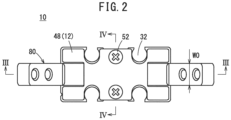
FIG. 2 is a plan view of the fulcrum opening/closing type air chuck shown inFIG. 1 ; -
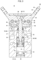
FIG. 3 is a cross-sectional view taken along line III-III ofFIG. 2 ; -
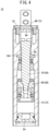
FIG. 4 is a cross-sectional view taken along line IV-IV ofFIG. 2 ; -
FIG. 5 is a view showing a state in which a first porous body of the fulcrum opening/closing type air chuck shown inFIG. 1 is attached; -
FIG. 6 is a perspective view of a second porous body of the fulcrum opening/closing type air chuck shown inFIG. 1 ; -
FIG. 7 is a perspective view of a third porous body of the fulcrum opening/closing type air chuck shown inFIG. 1 ; -
FIG. 8 is a view showing a state in which the third porous bodies of the fulcrum opening/closing type air chuck shown inFIG. 1 are attached; -
FIG. 9 is a view showing the flow of purge air in the fulcrum opening/closing type air chuck shown inFIG. 1 ; -
FIG. 10 is a view corresponding toFIG. 3 when a pair of fingers of the fulcrum opening/closing type air chuck shown inFIG. 1 move away from each other; and -
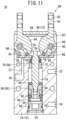
FIG. 11 is a view corresponding toFIG. 3 when the pair of fingers of the fulcrum opening/closing type air chuck shown inFIG. 1 approach each other. - As shown in
FIGS. 1 to 4 , a fulcrum opening/closingtype air chuck 10 according to an embodiment of the present invention includes abody 12, a pair offingers 80, adrive unit 58, and first to thirdporous bodies fingers 80 are pivotably supported on thebody 12. Thedrive unit 58 includes apiston 60 and adrive rod 70 integrally coupled to thepiston 60, and is disposed inside thebody 12. The pair offingers 80 are driven to move away from each other and approach each other by thedrive unit 58. In the following description, when terms in relation to up and down directions are used, for the sake of convenience, such terms refer to the directions shown inFIG. 3 , however, the actual arrangement of the constituent members and the like is not necessarily limited to this feature. - The
body 12 includes amain body 14 and anend plate 48. Theend plate 48 is attached to the upper end of themain body 14 byscrew members 52. Themain body 14 having a quadrangular prism shape includes acylinder hole 16 therein, and thepiston 60 is slidably disposed in thecylinder hole 16. The lower end of thecylinder hole 16 is closed by acap 54. A cylinder chamber formed by thecylinder hole 16 is partitioned into afirst pressure chamber 18 located above thepiston 60, and asecond pressure chamber 20 located below thepiston 60. Themain body 14 is provided with afirst port 22 for supplying/discharging air to/from thefirst pressure chamber 18, and asecond port 24 for supplying/discharging air to/from thesecond pressure chamber 20. - The
main body 14 is cut out parallel towide side surfaces 30 from one of a pair ofnarrow side surfaces 34 to the other thereof above thecylinder hole 16. That is, themain body 14 includes a pair ofside walls 28 above thecylinder hole 16.Reference numeral 47 denotes attachment holes for attaching thebody 12 to a conveying device (not shown) or the like. - A piston packing 62,
magnets 64, and awear ring 66 are mounted to the outer peripheral portion of thepiston 60. Thepiston packing 62 provides a seal between thefirst pressure chamber 18 and thesecond pressure chamber 20. Thewide side surfaces 30 of themain body 14 havesensor grooves 32. The magnetic flux of themagnets 64 can be detected by magnetic sensors (not shown) attached to thesensor grooves 32. Adamper 68 is attached to the upper end of thepiston 60. Thedamper 68 absorbs an impact when thepiston 60 moves to an upper end position. - The
drive rod 70 is inserted into abush 72 mounted to thecylinder hole 16, and is supported so as to be movable up and down. A rod packing 74 in sliding contact with thedrive rod 70 is mounted to the upper end of thecylinder hole 16. The rod packing 74 airtightly holds thefirst pressure chamber 18. A sealingmember 56 for keeping thesecond pressure chamber 20 airtight from the outside is mounted to the outer peripheral portion of thecap 54. Thedrive rod 70 extends upward from thecylinder hole 16. The upper end ofdrive rod 70 is provided with a pair ofarm portions 76 directed toward therespective fingers 80. A cylindricalrolling element 78 is rotatably supported at the distal end of eacharm portion 76. - Each
finger 80 is formed of a fan-shaped pivoting portion 82 and anelongated gripping portion 92. Thepivoting portion 82 and the grippingportion 92 have a constant width W0. Thepivoting portion 82 is disposed between the pair ofside walls 28 of themain body 14. Apivot support shaft 40 is mounted across the pair ofside walls 28 of themain body 14, and thepivot support shaft 40 is inserted into abush 88 mounted to the center of thepivoting portion 82. As a result, thefingers 80 are supported so as to be pivotable about thepivot support shafts 40. - The pivoting
portions 82 each include a firstcurved surface 84 facing theend plate 48, and a secondcurved surface 86 facing afitting recess 42 of themain body 14 described later. The firstcurved surface 84 and the secondcurved surface 86 each have a constant radius of curvature about the axis of thepivot support shaft 40. The radius of curvature of the firstcurved surface 84 is greater than the radius of curvature of the secondcurved surface 86. Further, the pivotingportion 82 has two end surfaces facing theside walls 28 of themain body 14. The end surfaces of the pivotingportion 82 are perpendicular to the axis of thepivot support shaft 40. The grippingportions 92 each extend radially outward from one circumferential end portion of the firstcurved surface 84 of each of the pivotingportions 82. - The pivoting
portions 82 each include agroove portion 90 extending to a predetermined depth from another circumferential end portion of the firstcurved surface 84. The rollingelements 78 supported by thearm portions 76 of thedrive rod 70 are disposed in thegroove portions 90 of the pivotingportions 82, and can move in thegroove portions 90 while rolling. As a result, the vertical linear motion of thedrive rod 70 is converted into the pivot motion of thefingers 80. When thedrive rod 70 moves upward, the pair offingers 80 pivot in a direction in which the pair ofgripping portions 92 move away from each other, and when thedrive rod 70 moves downward, the pair offingers 80 pivot in a direction in which the pair ofgripping portions 92 approach each other. - The
end plate 48 includes, at both ends thereof,cutout portions 50 to be passages of thegripping portions 92 when thefingers 80 pivot. The narrow side surfaces 34 of themain body 14 each have anopening 36 that opens between the pair ofside walls 28. The pivotingportions 82 of thefingers 80 and the first to thirdporous bodies body 12 from being directly connected to the outside through theopenings 36 of themain body 14 and thecutout portions 50 of theend plate 48. That is, a purgeair storage space 38 isolated from the outside is formed above thecylinder hole 16. - The first to third
porous bodies porous bodies porous bodies - The first to third
porous bodies fingers 80 have small deformation resistance and are easily deformed. Even if the first to thirdporous bodies fingers 80 at a predetermined pressure in order to reliably fill the gap between the first to thirdporous bodies fingers 80, resistance (sliding resistance) when thefingers 80 move is small. In the present embodiment, the first to thirdporous bodies - As shown in
FIG. 5 , the firstporous body 94 is formed in an elongated rectangular plate shape having a constant width W1. The firstporous body 94 is attached to the lower surface of theend plate 48 using, for example, an adhesive. The width W1 of the firstporous body 94 is equal to or slightly larger than the width W0 of the pivotingportions 82 of thefingers 80. In the entire pivot range of thefingers 80, the firstcurved surface 84 of the pivotingportion 82 of each of thefingers 80 comes into contact with the end portion of the firstporous body 94 in the lengthwise direction (seeFIG. 3 ). A portion of the firstporous body 94 that comes into contact with the firstcurved surface 84 is deformed by being pressed by the firstcurved surface 84. - As shown in
FIG. 6 , the secondporous body 96 includes an elongated plate-shapedbase portion 98, and a pair of steppedportions 106 bent in an L-shape from both ends of thebase portion 98. Thebase portion 98 is provided with, at the center thereof in the lengthwise direction, afirst hole portion 100 through which thedrive rod 70 is inserted. Further, thebase portion 98 is provided with, at one end portion thereof in the lengthwise direction, asecond hole portion 102 serving as a passage of purge air. Thebase portion 98 is provided with a pair of projectingportions 104 projecting from the vicinity of thefirst hole portion 100 to both sides. In a state before thedrive rod 70 is inserted into thefirst hole portion 100, the inner diameter of thefirst hole portion 100 is smaller than the outer diameter of thedrive rod 70. In other words, when thedrive rod 70 is inserted into thefirst hole portion 100, thefirst hole portion 100 expands. - As shown in
FIG. 3 , the secondporous body 96 is attached to themain body 14 so as to face the secondcurved surfaces 86 of the pivotingportions 82 of thefingers 80. Themain body 14 includes thefitting recess 42 whose bottom surface is a surface where the upper end of thecylinder hole 16 is opened. The secondporous body 96 including the steppedportions 106 is fitted into thefitting recess 42 of themain body 14. Themain body 14 includes recessedgrooves 44 on the inner sides of the pair of wide side surfaces 30, and the projectingportions 104 of the secondporous body 96 are fitted into the recessed grooves 44 (seeFIG. 4 ). By the projectingportions 104 of the secondporous body 96 being fitted into the recessedgrooves 44 of themain body 14, the center of the secondporous body 96 is prevented from being lifted by being dragged by thedrive rod 70 inserted into thefirst hole portion 100. - The width W2 of the stepped
portions 106 of the secondporous body 96 is equal to or slightly larger than the width W0 of the pivotingportions 82 of thefingers 80. In the entire pivot range of thefingers 80, the secondcurved surfaces 86 of the pivotingportions 82 of thefingers 80 come into contact withcorner portions 108 of the steppedportions 106 of the second porous body 96 (seeFIG. 3 ). The portion of the secondporous body 96 that comes into contact with each of the secondcurved surfaces 86 is deformed by being pressed by the secondcurved surface 86. - As shown in
FIG. 7 , the thirdporous bodies 110 are formed in an elongated rectangular plate shape. The thirdporous bodies 110 are attached to themain body 14 so as to face the end surfaces of the pivotingportions 82 of thefingers 80. As shown inFIG. 8 , themain body 14 includesfitting grooves 46 on the inner sides of the pair ofside walls 28, and the thirdporous bodies 110 are fitted into thefitting grooves 46. The thirdporous bodies 110 are disposed at four locations in total, correspondingly to the two end surfaces of the pivotingportion 82 of eachfinger 80. In the entire pivot range of thefingers 80, the end surfaces of the pivotingportions 82 of thefingers 80 come into surface contact with the thirdporous bodies 110 at a predetermined pressure. The thirdporous bodies 110 each include, at the center thereof in the length direction, ahole portion 112 through which thepivot support shaft 40 is inserted. - The
main body 14 includes athird port 26 to which purge air is supplied, and acommunication passage 27 that allows thethird port 26 to communicate with thesecond hole portion 102 of the second porous body 96 (seeFIG. 3 ). The purge air supplied from thethird port 26 passes through thecommunication passage 27 of themain body 14 and thesecond hole portion 102 of the secondporous body 96, and enters the purgeair storage space 38 to increase the pressure in the purgeair storage space 38. - The air filling the purge
air storage space 38 passes through the interior of the first to thirdporous bodies porous body 94 exposed to the outside between theend plate 48 and the firstcurved surface 84 of each of the pivoting portions 82 (seeFIGS. 1 and9 ). Further, air passes through the surface of the secondporous body 96 exposed to the outside between themain body 14 and the secondcurved surface 86 of each of the pivoting portions 82 (seeFIGS. 1 and9 ). Furthermore, air passes through the surface of the thirdporous body 110 exposed to the outside between themain body 14 and the end surface of each of the pivoting portions 82 (seeFIG. 1 ). - Next, an opening/closing operation of the fulcrum opening/closing
type air chuck 10 will be described with reference toFIGS. 10 and11 . The fulcrum opening/closingtype air chuck 10 is attached to, for example, a conveyance device that conveys a workpiece. As shown inFIG. 10 , a state in which the pair offingers 80 are aligned in a straight line is defined as an initial state. - The conveyance device (not shown) is driven to convey the fulcrum opening/closing
type air chuck 10 to a position where the fulcrum opening/closingtype air chuck 10 can grip a workpiece (not shown). Thereafter, a switching valve (not shown) is switched to a predetermined operating position, so that thefirst port 22 is connected to an air supply source (not shown) and thesecond port 24 is connected to an exhaust port (not shown). As a result, air is supplied to thefirst pressure chamber 18, and air in thesecond pressure chamber 20 is discharged, whereby thepiston 60 and thedrive rod 70 move downward. - When the
drive rod 70 moves downward, the pair offingers 80 pivot in a direction in which the pair ofgripping portions 92 approach each other. The pair offingers 80 pivot to a position where the pair ofgripping portions 92 abut against theend plate 48, whereby the fulcrum opening/closingtype air chuck 10 is brought into a closed state (seeFIG. 11 ), and the workpiece is sandwiched between the pair offingers 80. It should be noted that, according to the shape and size of the workpiece, an attachment member (not shown) can be attached to anattachment hole 93 provided in the grippingportion 92. - The conveyance device is driven again to convey the fulcrum opening/closing
type air chuck 10 to a place where the fulcrum opening/closingtype air chuck 10 releases the workpiece. Thereafter, the switching valve is switched to another operation position, so that thefirst port 22 is connected to the exhaust port and thesecond port 24 is connected to the air supply source. As a result, air is supplied to thesecond pressure chamber 20, and air in thefirst pressure chamber 18 is discharged, whereby thepiston 60 and thedrive rod 70 move upward. When thedrive rod 70 moves upward, the pair offingers 80 pivot in a direction in which the pair ofgripping portions 92 move away from each other, and the workpiece is released. Thepiston 60 moves upward until thedamper 68 abuts against thebush 72, and the pair offingers 80 are again aligned in a straight line (seeFIG. 10 ). - Next, the dust-proof function of the fulcrum opening/closing
type air chuck 10 will be described. The purgeair storage space 38 is isolated from the outside by the pivotingportions 82 of thefingers 80 and the first to thirdporous bodies porous bodies porous bodies porous bodies porous bodies - The
third port 26 is constantly connected to an air supply source. That is, the purge air is constantly supplied to thethird port 26. The purge air supplied from thethird port 26 enters the purgeair storage space 38 to increase the pressure in the purgeair storage space 38. Then, the air filling the purgeair storage space 38 passes through the interior of the first to thirdporous bodies porous bodies body 12 and the pivotingportions 82. - The pressure in the purge
air storage space 38 is sufficiently higher than the pressure (atmospheric pressure) on the surfaces of the first to thirdporous bodies porous bodies porous bodies porous bodies - The fulcrum opening/closing
type air chuck 10 according to the present embodiment includes the firstporous body 94 that is attached to theend plate 48 and comes into contact with thefingers 80. Further, the fulcrum opening/closingtype air chuck 10 includes the secondporous body 96 and the thirdporous bodies 110 that are attached to themain body 14 and come into contact with thefingers 80. Furthermore, the purge air passes through the first to thirdporous bodies body 12 without increasing the sliding resistance of thefingers 80. By preventing the entry of the dust, durability of the rod packing 74, the piston packing 62, and the like disposed in thecylinder hole 16 is improved. - In the present embodiment, the purge air is constantly supplied, but when the fulcrum opening/closing
type air chuck 10 is used in an environment where there is little dust outside, the purge air may be intermittently supplied.
Claims (7)
- A fulcrum opening/closing type air chuck (10) in which a pair of fingers (80) are each supported so as to be pivotable about a pivot support shaft (40) attached to a body (14, 48), and a drive unit (60, 70) configured to drive the pair of fingers to move away from each other and approach each other is disposed inside the body,the fulcrum opening/closing type air chuck comprising a porous body (94, 96, 110) attached to the body and configured to come into contact with the fingers, whereinpurge air passes through the porous body and is discharged to outside.
- The fulcrum opening/closing type air chuck according to claim 1, whereinthe fingers are each formed of a pivoting portion (82) and a gripping portion (92), the pivoting portion including a first curved surface (84) and a second curved surface (86),the body includes a main body (14) and an end plate (48), anda first porous body (94) configured to come into contact with the first curved surfaces is attached to the end plate, and a second porous body (96) configured to come into contact with the second curved surfaces is attached to the main body.
- The fulcrum opening/closing type air chuck according to claim 2, whereinthe second porous body having a rectangular shape includes, at both ends thereof, stepped portions (106) configured to attach the second porous body to the main body by fitting, andthe second curved surfaces come into contact with corner portions (108) of the stepped portions of the second porous body.
- The fulcrum opening/closing type air chuck according to claim 2, wherein
the second porous body includes a hole portion (102) serving as a passage of purge air. - The fulcrum opening/closing type air chuck according to claim 2, whereinthe drive unit includes a drive rod (70) coupled to a piston (60), andthe second porous body includes a hole portion (100) through which the drive rod is inserted.
- The fulcrum opening/closing type air chuck according to claim 2, whereinthe pivoting portions each include an end surface perpendicular to an axis of the pivot support shaft, anda third porous body (110) configured to come into contact with the end surface of each of the pivoting portions is attached to the main body.
- The fulcrum opening/closing type air chuck according to claim 6, wherein
the third porous body includes a hole portion (112) through which the pivot support shaft is inserted.
Applications Claiming Priority (1)
| Application Number | Priority Date | Filing Date | Title |
|---|---|---|---|
| JP2021187797A JP7739966B2 (en) | 2021-11-18 | 2021-11-18 | Support point opening and closing type air chuck |
Publications (2)
| Publication Number | Publication Date |
|---|---|
| EP4183519A1 true EP4183519A1 (en) | 2023-05-24 |
| EP4183519B1 EP4183519B1 (en) | 2024-07-24 |
Family
ID=84245669
Family Applications (1)
| Application Number | Title | Priority Date | Filing Date |
|---|---|---|---|
| EP22205443.9A Active EP4183519B1 (en) | 2021-11-18 | 2022-11-04 | Fulcrum opening/closing type air chuck |
Country Status (6)
| Country | Link |
|---|---|
| US (1) | US20230150123A1 (en) |
| EP (1) | EP4183519B1 (en) |
| JP (1) | JP7739966B2 (en) |
| KR (1) | KR20230073097A (en) |
| CN (1) | CN116135489A (en) |
| TW (1) | TW202333922A (en) |
Citations (3)
| Publication number | Priority date | Publication date | Assignee | Title |
|---|---|---|---|---|
| JPH1080888A (en) | 1996-09-06 | 1998-03-31 | Smc Corp | Chuck device |
| EP0761390B1 (en) * | 1995-08-30 | 2001-10-31 | David Fischer | Clamping device |
| DE20302384U1 (en) * | 2003-02-14 | 2004-06-24 | Wilhelm Karmann Gmbh | Clamping device for workpieces has movable clamping element running inside centring socket and engaging through elastic separating device which keeps dirt away from drive device |
Family Cites Families (9)
| Publication number | Priority date | Publication date | Assignee | Title |
|---|---|---|---|---|
| JP3867514B2 (en) | 2001-05-07 | 2007-01-10 | 株式会社デンソー | Gripping device |
| US20030106493A1 (en) | 2001-12-07 | 2003-06-12 | Christian Joann F.C. | Shield for a robot arm |
| ITBS20070179A1 (en) | 2007-11-16 | 2009-05-17 | Gimatic Spa | ANGLE PNEUMATIC CLAMP |
| JP5688603B2 (en) | 2009-09-09 | 2015-03-25 | Smc株式会社 | Air cylinder |
| JP2013067445A (en) | 2011-09-20 | 2013-04-18 | Murata Machinery Ltd | Winding device |
| DE102012024675B4 (en) | 2012-12-18 | 2021-08-26 | Günther Zimmer | Gripping device with housing-guided slide |
| JP6508570B2 (en) | 2015-04-21 | 2019-05-08 | 日立金属株式会社 | Gripping device |
| JP6802120B2 (en) | 2017-07-26 | 2020-12-16 | 株式会社エクセディ | Clutch release device |
| CN112720446B (en) | 2021-01-07 | 2025-01-24 | 湖南军成科技有限公司 | A positive pressure explosion-proof manipulator |
-
2021
- 2021-11-18 JP JP2021187797A patent/JP7739966B2/en active Active
-
2022
- 2022-10-24 US US18/049,062 patent/US20230150123A1/en active Pending
- 2022-10-27 TW TW111140897A patent/TW202333922A/en unknown
- 2022-11-04 EP EP22205443.9A patent/EP4183519B1/en active Active
- 2022-11-08 KR KR1020220147699A patent/KR20230073097A/en active Pending
- 2022-11-17 CN CN202211439875.2A patent/CN116135489A/en active Pending
Patent Citations (4)
| Publication number | Priority date | Publication date | Assignee | Title |
|---|---|---|---|---|
| EP0761390B1 (en) * | 1995-08-30 | 2001-10-31 | David Fischer | Clamping device |
| JPH1080888A (en) | 1996-09-06 | 1998-03-31 | Smc Corp | Chuck device |
| US5904358A (en) * | 1996-09-06 | 1999-05-18 | Smc Kabushiki Kaisha | Chuck device |
| DE20302384U1 (en) * | 2003-02-14 | 2004-06-24 | Wilhelm Karmann Gmbh | Clamping device for workpieces has movable clamping element running inside centring socket and engaging through elastic separating device which keeps dirt away from drive device |
Also Published As
| Publication number | Publication date |
|---|---|
| CN116135489A (en) | 2023-05-19 |
| TW202333922A (en) | 2023-09-01 |
| US20230150123A1 (en) | 2023-05-18 |
| JP2023074709A (en) | 2023-05-30 |
| EP4183519B1 (en) | 2024-07-24 |
| KR20230073097A (en) | 2023-05-25 |
| JP7739966B2 (en) | 2025-09-17 |
Similar Documents
| Publication | Publication Date | Title |
|---|---|---|
| US7806393B2 (en) | Clamp apparatus | |
| US6641123B2 (en) | Clamp apparatus | |
| KR100347910B1 (en) | Clamp Apparatus | |
| US10183335B2 (en) | Chuck apparatus | |
| US6694865B2 (en) | Belt guide mechanism | |
| US6997447B2 (en) | Clamp apparatus | |
| JP3568851B2 (en) | Clamping device | |
| US20070057214A1 (en) | Valve for essentially gastight closing a flow path | |
| EP4183519B1 (en) | Fulcrum opening/closing type air chuck | |
| JPH0256558B2 (en) | ||
| JP3867514B2 (en) | Gripping device | |
| US20220241871A1 (en) | Chuck apparatus | |
| US11555546B2 (en) | Shake-prevention-mechanism—including gate valve | |
| JP3087910U (en) | Lock holding mechanism | |
| JP2005329531A (en) | Holding device for rod | |
| KR20220136093A (en) | Adsorption apparatus of the moving device | |
| JP2001187906A (en) | Transferring device | |
| JP4205913B2 (en) | Differential exhaust seal device | |
| JPH11198082A (en) | Fluid pressure hand with rubber cover | |
| JP2002323149A (en) | Gate valve | |
| JP4770382B2 (en) | Liquid transfer device | |
| JP3256490B2 (en) | Gate valve | |
| JPH087156Y2 (en) | Position control valve | |
| KR20240079159A (en) | Hand of Industrial Robot and Industrial Robot | |
| JPH0624207U (en) | Rodless cylinder |
Legal Events
| Date | Code | Title | Description |
|---|---|---|---|
| PUAI | Public reference made under article 153(3) epc to a published international application that has entered the european phase |
Free format text: ORIGINAL CODE: 0009012 |
|
| STAA | Information on the status of an ep patent application or granted ep patent |
Free format text: STATUS: THE APPLICATION HAS BEEN PUBLISHED |
|
| AK | Designated contracting states |
Kind code of ref document: A1 Designated state(s): AL AT BE BG CH CY CZ DE DK EE ES FI FR GB GR HR HU IE IS IT LI LT LU LV MC ME MK MT NL NO PL PT RO RS SE SI SK SM TR |
|
| STAA | Information on the status of an ep patent application or granted ep patent |
Free format text: STATUS: REQUEST FOR EXAMINATION WAS MADE |
|
| 17P | Request for examination filed |
Effective date: 20231011 |
|
| RBV | Designated contracting states (corrected) |
Designated state(s): AL AT BE BG CH CY CZ DE DK EE ES FI FR GB GR HR HU IE IS IT LI LT LU LV MC ME MK MT NL NO PL PT RO RS SE SI SK SM TR |
|
| REG | Reference to a national code |
Ref country code: DE Ref legal event code: R079 Free format text: PREVIOUS MAIN CLASS: B25B0005060000 Ipc: B23B0031180000 Ref country code: DE Ref legal event code: R079 Ref document number: 602022004799 Country of ref document: DE Free format text: PREVIOUS MAIN CLASS: B25B0005060000 Ipc: B23B0031180000 |
|
| GRAP | Despatch of communication of intention to grant a patent |
Free format text: ORIGINAL CODE: EPIDOSNIGR1 |
|
| STAA | Information on the status of an ep patent application or granted ep patent |
Free format text: STATUS: GRANT OF PATENT IS INTENDED |
|
| RIC1 | Information provided on ipc code assigned before grant |
Ipc: B25B 5/06 20060101ALI20240124BHEP Ipc: B25J 19/00 20060101ALI20240124BHEP Ipc: B25J 15/02 20060101ALI20240124BHEP Ipc: B23B 31/18 20060101AFI20240124BHEP |
|
| INTG | Intention to grant announced |
Effective date: 20240219 |
|
| GRAS | Grant fee paid |
Free format text: ORIGINAL CODE: EPIDOSNIGR3 |
|
| GRAA | (expected) grant |
Free format text: ORIGINAL CODE: 0009210 |
|
| STAA | Information on the status of an ep patent application or granted ep patent |
Free format text: STATUS: THE PATENT HAS BEEN GRANTED |
|
| AK | Designated contracting states |
Kind code of ref document: B1 Designated state(s): AL AT BE BG CH CY CZ DE DK EE ES FI FR GB GR HR HU IE IS IT LI LT LU LV MC ME MK MT NL NO PL PT RO RS SE SI SK SM TR |
|
| REG | Reference to a national code |
Ref country code: GB Ref legal event code: FG4D |
|
| REG | Reference to a national code |
Ref country code: CH Ref legal event code: EP |
|
| REG | Reference to a national code |
Ref country code: DE Ref legal event code: R096 Ref document number: 602022004799 Country of ref document: DE |
|
| REG | Reference to a national code |
Ref country code: IE Ref legal event code: FG4D |
|
| REG | Reference to a national code |
Ref country code: LT Ref legal event code: MG9D |
|
| REG | Reference to a national code |
Ref country code: NL Ref legal event code: MP Effective date: 20240724 |
|
| PG25 | Lapsed in a contracting state [announced via postgrant information from national office to epo] |
Ref country code: PT Free format text: LAPSE BECAUSE OF FAILURE TO SUBMIT A TRANSLATION OF THE DESCRIPTION OR TO PAY THE FEE WITHIN THE PRESCRIBED TIME-LIMIT Effective date: 20241125 |
|
| REG | Reference to a national code |
Ref country code: AT Ref legal event code: MK05 Ref document number: 1705866 Country of ref document: AT Kind code of ref document: T Effective date: 20240724 |
|
| PG25 | Lapsed in a contracting state [announced via postgrant information from national office to epo] |
Ref country code: NL Free format text: LAPSE BECAUSE OF FAILURE TO SUBMIT A TRANSLATION OF THE DESCRIPTION OR TO PAY THE FEE WITHIN THE PRESCRIBED TIME-LIMIT Effective date: 20240724 |
|
| PG25 | Lapsed in a contracting state [announced via postgrant information from national office to epo] |
Ref country code: PT Free format text: LAPSE BECAUSE OF FAILURE TO SUBMIT A TRANSLATION OF THE DESCRIPTION OR TO PAY THE FEE WITHIN THE PRESCRIBED TIME-LIMIT Effective date: 20241125 Ref country code: NL Free format text: LAPSE BECAUSE OF FAILURE TO SUBMIT A TRANSLATION OF THE DESCRIPTION OR TO PAY THE FEE WITHIN THE PRESCRIBED TIME-LIMIT Effective date: 20240724 |
|
| PG25 | Lapsed in a contracting state [announced via postgrant information from national office to epo] |
Ref country code: NO Free format text: LAPSE BECAUSE OF FAILURE TO SUBMIT A TRANSLATION OF THE DESCRIPTION OR TO PAY THE FEE WITHIN THE PRESCRIBED TIME-LIMIT Effective date: 20241024 |
|
| PG25 | Lapsed in a contracting state [announced via postgrant information from national office to epo] |
Ref country code: FI Free format text: LAPSE BECAUSE OF FAILURE TO SUBMIT A TRANSLATION OF THE DESCRIPTION OR TO PAY THE FEE WITHIN THE PRESCRIBED TIME-LIMIT Effective date: 20240724 Ref country code: PL Free format text: LAPSE BECAUSE OF FAILURE TO SUBMIT A TRANSLATION OF THE DESCRIPTION OR TO PAY THE FEE WITHIN THE PRESCRIBED TIME-LIMIT Effective date: 20240724 Ref country code: GR Free format text: LAPSE BECAUSE OF FAILURE TO SUBMIT A TRANSLATION OF THE DESCRIPTION OR TO PAY THE FEE WITHIN THE PRESCRIBED TIME-LIMIT Effective date: 20241025 |
|
| PG25 | Lapsed in a contracting state [announced via postgrant information from national office to epo] |
Ref country code: BG Free format text: LAPSE BECAUSE OF FAILURE TO SUBMIT A TRANSLATION OF THE DESCRIPTION OR TO PAY THE FEE WITHIN THE PRESCRIBED TIME-LIMIT Effective date: 20240724 |
|
| PG25 | Lapsed in a contracting state [announced via postgrant information from national office to epo] |
Ref country code: LV Free format text: LAPSE BECAUSE OF FAILURE TO SUBMIT A TRANSLATION OF THE DESCRIPTION OR TO PAY THE FEE WITHIN THE PRESCRIBED TIME-LIMIT Effective date: 20240724 |
|
| PG25 | Lapsed in a contracting state [announced via postgrant information from national office to epo] |
Ref country code: IS Free format text: LAPSE BECAUSE OF FAILURE TO SUBMIT A TRANSLATION OF THE DESCRIPTION OR TO PAY THE FEE WITHIN THE PRESCRIBED TIME-LIMIT Effective date: 20241124 Ref country code: AT Free format text: LAPSE BECAUSE OF FAILURE TO SUBMIT A TRANSLATION OF THE DESCRIPTION OR TO PAY THE FEE WITHIN THE PRESCRIBED TIME-LIMIT Effective date: 20240724 |
|
| PG25 | Lapsed in a contracting state [announced via postgrant information from national office to epo] |
Ref country code: HR Free format text: LAPSE BECAUSE OF FAILURE TO SUBMIT A TRANSLATION OF THE DESCRIPTION OR TO PAY THE FEE WITHIN THE PRESCRIBED TIME-LIMIT Effective date: 20240724 |
|
| PG25 | Lapsed in a contracting state [announced via postgrant information from national office to epo] |
Ref country code: ES Free format text: LAPSE BECAUSE OF FAILURE TO SUBMIT A TRANSLATION OF THE DESCRIPTION OR TO PAY THE FEE WITHIN THE PRESCRIBED TIME-LIMIT Effective date: 20240724 Ref country code: RS Free format text: LAPSE BECAUSE OF FAILURE TO SUBMIT A TRANSLATION OF THE DESCRIPTION OR TO PAY THE FEE WITHIN THE PRESCRIBED TIME-LIMIT Effective date: 20241024 |
|
| PG25 | Lapsed in a contracting state [announced via postgrant information from national office to epo] |
Ref country code: RS Free format text: LAPSE BECAUSE OF FAILURE TO SUBMIT A TRANSLATION OF THE DESCRIPTION OR TO PAY THE FEE WITHIN THE PRESCRIBED TIME-LIMIT Effective date: 20241024 Ref country code: PL Free format text: LAPSE BECAUSE OF FAILURE TO SUBMIT A TRANSLATION OF THE DESCRIPTION OR TO PAY THE FEE WITHIN THE PRESCRIBED TIME-LIMIT Effective date: 20240724 Ref country code: NO Free format text: LAPSE BECAUSE OF FAILURE TO SUBMIT A TRANSLATION OF THE DESCRIPTION OR TO PAY THE FEE WITHIN THE PRESCRIBED TIME-LIMIT Effective date: 20241024 Ref country code: LV Free format text: LAPSE BECAUSE OF FAILURE TO SUBMIT A TRANSLATION OF THE DESCRIPTION OR TO PAY THE FEE WITHIN THE PRESCRIBED TIME-LIMIT Effective date: 20240724 Ref country code: IS Free format text: LAPSE BECAUSE OF FAILURE TO SUBMIT A TRANSLATION OF THE DESCRIPTION OR TO PAY THE FEE WITHIN THE PRESCRIBED TIME-LIMIT Effective date: 20241124 Ref country code: HR Free format text: LAPSE BECAUSE OF FAILURE TO SUBMIT A TRANSLATION OF THE DESCRIPTION OR TO PAY THE FEE WITHIN THE PRESCRIBED TIME-LIMIT Effective date: 20240724 Ref country code: GR Free format text: LAPSE BECAUSE OF FAILURE TO SUBMIT A TRANSLATION OF THE DESCRIPTION OR TO PAY THE FEE WITHIN THE PRESCRIBED TIME-LIMIT Effective date: 20241025 Ref country code: FI Free format text: LAPSE BECAUSE OF FAILURE TO SUBMIT A TRANSLATION OF THE DESCRIPTION OR TO PAY THE FEE WITHIN THE PRESCRIBED TIME-LIMIT Effective date: 20240724 Ref country code: ES Free format text: LAPSE BECAUSE OF FAILURE TO SUBMIT A TRANSLATION OF THE DESCRIPTION OR TO PAY THE FEE WITHIN THE PRESCRIBED TIME-LIMIT Effective date: 20240724 Ref country code: BG Free format text: LAPSE BECAUSE OF FAILURE TO SUBMIT A TRANSLATION OF THE DESCRIPTION OR TO PAY THE FEE WITHIN THE PRESCRIBED TIME-LIMIT Effective date: 20240724 Ref country code: AT Free format text: LAPSE BECAUSE OF FAILURE TO SUBMIT A TRANSLATION OF THE DESCRIPTION OR TO PAY THE FEE WITHIN THE PRESCRIBED TIME-LIMIT Effective date: 20240724 |
|
| PG25 | Lapsed in a contracting state [announced via postgrant information from national office to epo] |
Ref country code: SM Free format text: LAPSE BECAUSE OF FAILURE TO SUBMIT A TRANSLATION OF THE DESCRIPTION OR TO PAY THE FEE WITHIN THE PRESCRIBED TIME-LIMIT Effective date: 20240724 Ref country code: DK Free format text: LAPSE BECAUSE OF FAILURE TO SUBMIT A TRANSLATION OF THE DESCRIPTION OR TO PAY THE FEE WITHIN THE PRESCRIBED TIME-LIMIT Effective date: 20240724 Ref country code: RO Free format text: LAPSE BECAUSE OF FAILURE TO SUBMIT A TRANSLATION OF THE DESCRIPTION OR TO PAY THE FEE WITHIN THE PRESCRIBED TIME-LIMIT Effective date: 20240724 |
|
| PG25 | Lapsed in a contracting state [announced via postgrant information from national office to epo] |
Ref country code: EE Free format text: LAPSE BECAUSE OF FAILURE TO SUBMIT A TRANSLATION OF THE DESCRIPTION OR TO PAY THE FEE WITHIN THE PRESCRIBED TIME-LIMIT Effective date: 20240724 |
|
| PG25 | Lapsed in a contracting state [announced via postgrant information from national office to epo] |
Ref country code: CZ Free format text: LAPSE BECAUSE OF FAILURE TO SUBMIT A TRANSLATION OF THE DESCRIPTION OR TO PAY THE FEE WITHIN THE PRESCRIBED TIME-LIMIT Effective date: 20240724 |
|
| REG | Reference to a national code |
Ref country code: DE Ref legal event code: R097 Ref document number: 602022004799 Country of ref document: DE |
|
| PG25 | Lapsed in a contracting state [announced via postgrant information from national office to epo] |
Ref country code: IT Free format text: LAPSE BECAUSE OF FAILURE TO SUBMIT A TRANSLATION OF THE DESCRIPTION OR TO PAY THE FEE WITHIN THE PRESCRIBED TIME-LIMIT Effective date: 20240724 Ref country code: SK Free format text: LAPSE BECAUSE OF FAILURE TO SUBMIT A TRANSLATION OF THE DESCRIPTION OR TO PAY THE FEE WITHIN THE PRESCRIBED TIME-LIMIT Effective date: 20240724 |
|
| PLBE | No opposition filed within time limit |
Free format text: ORIGINAL CODE: 0009261 |
|
| STAA | Information on the status of an ep patent application or granted ep patent |
Free format text: STATUS: NO OPPOSITION FILED WITHIN TIME LIMIT |
|
| RAP4 | Party data changed (patent owner data changed or rights of a patent transferred) |
Owner name: SMC CORPORATION |
|
| 26N | No opposition filed |
Effective date: 20250425 |
|
| PG25 | Lapsed in a contracting state [announced via postgrant information from national office to epo] |
Ref country code: MC Free format text: LAPSE BECAUSE OF FAILURE TO SUBMIT A TRANSLATION OF THE DESCRIPTION OR TO PAY THE FEE WITHIN THE PRESCRIBED TIME-LIMIT Effective date: 20240724 |
|
| PG25 | Lapsed in a contracting state [announced via postgrant information from national office to epo] |
Ref country code: LU Free format text: LAPSE BECAUSE OF NON-PAYMENT OF DUE FEES Effective date: 20241104 |
|
| REG | Reference to a national code |
Ref country code: BE Ref legal event code: MM Effective date: 20241130 |
|
| PG25 | Lapsed in a contracting state [announced via postgrant information from national office to epo] |
Ref country code: SE Free format text: LAPSE BECAUSE OF FAILURE TO SUBMIT A TRANSLATION OF THE DESCRIPTION OR TO PAY THE FEE WITHIN THE PRESCRIBED TIME-LIMIT Effective date: 20240724 |
|
| PG25 | Lapsed in a contracting state [announced via postgrant information from national office to epo] |
Ref country code: BE Free format text: LAPSE BECAUSE OF NON-PAYMENT OF DUE FEES Effective date: 20241130 |
|
| PG25 | Lapsed in a contracting state [announced via postgrant information from national office to epo] |
Ref country code: FR Free format text: LAPSE BECAUSE OF NON-PAYMENT OF DUE FEES Effective date: 20241130 |
|
| PG25 | Lapsed in a contracting state [announced via postgrant information from national office to epo] |
Ref country code: IE Free format text: LAPSE BECAUSE OF NON-PAYMENT OF DUE FEES Effective date: 20241104 |
|
| PG25 | Lapsed in a contracting state [announced via postgrant information from national office to epo] |
Ref country code: HU Free format text: LAPSE BECAUSE OF FAILURE TO SUBMIT A TRANSLATION OF THE DESCRIPTION OR TO PAY THE FEE WITHIN THE PRESCRIBED TIME-LIMIT; INVALID AB INITIO Effective date: 20221104 |
|
| PG25 | Lapsed in a contracting state [announced via postgrant information from national office to epo] |
Ref country code: CY Free format text: LAPSE BECAUSE OF FAILURE TO SUBMIT A TRANSLATION OF THE DESCRIPTION OR TO PAY THE FEE WITHIN THE PRESCRIBED TIME-LIMIT; INVALID AB INITIO Effective date: 20221104 |
|
| PGFP | Annual fee paid to national office [announced via postgrant information from national office to epo] |
Ref country code: DE Payment date: 20260121 Year of fee payment: 4 |