EP4183438A1 - Catheter - Google Patents
Catheter Download PDFInfo
- Publication number
- EP4183438A1 EP4183438A1 EP20945024.6A EP20945024A EP4183438A1 EP 4183438 A1 EP4183438 A1 EP 4183438A1 EP 20945024 A EP20945024 A EP 20945024A EP 4183438 A1 EP4183438 A1 EP 4183438A1
- Authority
- EP
- European Patent Office
- Prior art keywords
- slit part
- catheter
- shaft
- proximal end
- distal end
- Prior art date
- Legal status (The legal status is an assumption and is not a legal conclusion. Google has not performed a legal analysis and makes no representation as to the accuracy of the status listed.)
- Withdrawn
Links
- 230000007423 decrease Effects 0.000 claims description 7
- 239000007788 liquid Substances 0.000 description 9
- 239000000463 material Substances 0.000 description 7
- 230000000149 penetrating effect Effects 0.000 description 5
- 210000004204 blood vessel Anatomy 0.000 description 4
- 239000002872 contrast media Substances 0.000 description 4
- 230000003014 reinforcing effect Effects 0.000 description 4
- 239000011347 resin Substances 0.000 description 3
- 229920005989 resin Polymers 0.000 description 3
- 239000004952 Polyamide Substances 0.000 description 2
- 229910045601 alloy Inorganic materials 0.000 description 2
- 239000000956 alloy Substances 0.000 description 2
- 229920001971 elastomer Polymers 0.000 description 2
- 239000000806 elastomer Substances 0.000 description 2
- 239000002184 metal Substances 0.000 description 2
- 230000002093 peripheral effect Effects 0.000 description 2
- 239000002504 physiological saline solution Substances 0.000 description 2
- 229920002647 polyamide Polymers 0.000 description 2
- 229920000728 polyester Polymers 0.000 description 2
- 239000000243 solution Substances 0.000 description 2
- 230000002785 anti-thrombosis Effects 0.000 description 1
- 239000003146 anticoagulant agent Substances 0.000 description 1
- 238000005219 brazing Methods 0.000 description 1
- 210000004351 coronary vessel Anatomy 0.000 description 1
- 230000003247 decreasing effect Effects 0.000 description 1
- 230000000694 effects Effects 0.000 description 1
- 229920002313 fluoropolymer Polymers 0.000 description 1
- KHYBPSFKEHXSLX-UHFFFAOYSA-N iminotitanium Chemical compound [Ti]=N KHYBPSFKEHXSLX-UHFFFAOYSA-N 0.000 description 1
- 238000000034 method Methods 0.000 description 1
- 238000012986 modification Methods 0.000 description 1
- 230000004048 modification Effects 0.000 description 1
- 229910001000 nickel titanium Inorganic materials 0.000 description 1
- 229920000098 polyolefin Polymers 0.000 description 1
- 229920002635 polyurethane Polymers 0.000 description 1
- 239000004814 polyurethane Substances 0.000 description 1
- 229920003225 polyurethane elastomer Polymers 0.000 description 1
- 239000012779 reinforcing material Substances 0.000 description 1
- 229920005573 silicon-containing polymer Polymers 0.000 description 1
- 239000010935 stainless steel Substances 0.000 description 1
- 229910001220 stainless steel Inorganic materials 0.000 description 1
- 230000002792 vascular Effects 0.000 description 1
- 238000003466 welding Methods 0.000 description 1
Images

Classifications
-
- A—HUMAN NECESSITIES
- A61—MEDICAL OR VETERINARY SCIENCE; HYGIENE
- A61M—DEVICES FOR INTRODUCING MEDIA INTO, OR ONTO, THE BODY; DEVICES FOR TRANSDUCING BODY MEDIA OR FOR TAKING MEDIA FROM THE BODY; DEVICES FOR PRODUCING OR ENDING SLEEP OR STUPOR
- A61M25/00—Catheters; Hollow probes
- A61M25/0043—Catheters; Hollow probes characterised by structural features
- A61M25/005—Catheters; Hollow probes characterised by structural features with embedded materials for reinforcement, e.g. wires, coils, braids
- A61M25/0052—Localized reinforcement, e.g. where only a specific part of the catheter is reinforced, for rapid exchange guidewire port
-
- A—HUMAN NECESSITIES
- A61—MEDICAL OR VETERINARY SCIENCE; HYGIENE
- A61M—DEVICES FOR INTRODUCING MEDIA INTO, OR ONTO, THE BODY; DEVICES FOR TRANSDUCING BODY MEDIA OR FOR TAKING MEDIA FROM THE BODY; DEVICES FOR PRODUCING OR ENDING SLEEP OR STUPOR
- A61M25/00—Catheters; Hollow probes
- A61M25/0043—Catheters; Hollow probes characterised by structural features
- A61M25/0054—Catheters; Hollow probes characterised by structural features with regions for increasing flexibility
-
- A—HUMAN NECESSITIES
- A61—MEDICAL OR VETERINARY SCIENCE; HYGIENE
- A61M—DEVICES FOR INTRODUCING MEDIA INTO, OR ONTO, THE BODY; DEVICES FOR TRANSDUCING BODY MEDIA OR FOR TAKING MEDIA FROM THE BODY; DEVICES FOR PRODUCING OR ENDING SLEEP OR STUPOR
- A61M25/00—Catheters; Hollow probes
- A61M25/0043—Catheters; Hollow probes characterised by structural features
- A61M2025/0059—Catheters; Hollow probes characterised by structural features having means for preventing the catheter, sheath or lumens from collapsing due to outer forces, e.g. compressing forces, or caused by twisting or kinking
-
- A—HUMAN NECESSITIES
- A61—MEDICAL OR VETERINARY SCIENCE; HYGIENE
- A61M—DEVICES FOR INTRODUCING MEDIA INTO, OR ONTO, THE BODY; DEVICES FOR TRANSDUCING BODY MEDIA OR FOR TAKING MEDIA FROM THE BODY; DEVICES FOR PRODUCING OR ENDING SLEEP OR STUPOR
- A61M25/00—Catheters; Hollow probes
- A61M25/0043—Catheters; Hollow probes characterised by structural features
- A61M25/005—Catheters; Hollow probes characterised by structural features with embedded materials for reinforcement, e.g. wires, coils, braids
- A61M25/0051—Catheters; Hollow probes characterised by structural features with embedded materials for reinforcement, e.g. wires, coils, braids made from fenestrated or weakened tubing layer
-
- A—HUMAN NECESSITIES
- A61—MEDICAL OR VETERINARY SCIENCE; HYGIENE
- A61M—DEVICES FOR INTRODUCING MEDIA INTO, OR ONTO, THE BODY; DEVICES FOR TRANSDUCING BODY MEDIA OR FOR TAKING MEDIA FROM THE BODY; DEVICES FOR PRODUCING OR ENDING SLEEP OR STUPOR
- A61M25/00—Catheters; Hollow probes
- A61M25/10—Balloon catheters
Definitions
- This disclosure relates to a catheter.
- a catheter or the like is used to treat a site in a body cavity such as a blood vessel.
- a catheter including a metal hypotube, a resin outer tube provided on a position closer to a distal end side (balloon side) than the hypotube, and a core wire provided across the hypotube and the outer tube is known (see, for example, Patent Literature 1).
- a catheter including a metal hypotube, a spiral notch on a distal end side (balloon side) of the hypotube, and a resin outer tube covering the hypotube is known (see, for example, Patent Literature 2).
- the core wire is provided as a rigid reinforcing material, and is fixed to a portion of an inner peripheral surface of the hypotube in a circumferential direction. Hence, the directionality is exhibited when the hypotube and the outer tube are bent, resulting in poor operability.
- An object of the disclosure is to provide a catheter capable of preventing directionality from being exhibited when bent and having improved operability.
- Some aspects of this disclosure include:
- the disclosure can provide a catheter capable of preventing the directionality from being exhibited when bent, and having improved operability.
- the catheter includes a hollow shaft and an outer shaft arranged at an outer periphery of the hollow shaft, wherein the hollow shaft has a slit part, in which a plurality of slits extending spirally is formed, and proximal ends of the slits are each formed at a same axial position and at equal intervals in the circumferential direction.
- the catheter according to the embodiment is described with reference to the enclosed drawings.
- the disclosure is not limited to the embodiment described in the drawings.
- the catheter being a balloon catheter will be illustrated and described.
- the size of the catheter in drawings is a size illustrated to facilitate understanding of the embodiment, and does not correspond to the actual size.
- a distal end side indicates a side on which a distal tip is located in the longitudinal direction of the catheter.
- a “proximal end side (proximal side)” indicates a side opposite to the distal end side in the longitudinal direction.
- a “distal end” indicates an end part on the distal end side of each member forming the catheter.
- a “proximal end” indicates an end part on the proximal end side of each member forming the catheter.
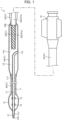
- FIG. 1 is a schematic longitudinal sectional view of the catheter 1 according to the embodiment.
- the catheter 1 is schematically configured of an inner shaft 11, a distal tip 21, a balloon 31, an outer shaft 41, a hollow shaft 51, and a connector 61.
- the inner shaft 11 is a cylindrical (hollow-shaped) shaft.
- the inner shaft 11 has an inner cavity 11a penetrating along the longitudinal direction.
- the distal end of the inner shaft 11 can be connected to, for example, a distal tip 21 described later.
- a proximal end portion of the inner shaft 11 is connected to, for example, a second outer shaft portion 43 of the outer shaft 41 described later, and can be arranged so that an opening 11b at the proximal end of the inner cavity 11a faces the outside.
- Two annular markers 12 are attached to an outer periphery of a portion covered by the balloon 31 described later of the inner shaft 11.
- the markers 12 are made of a radiopaque material.
- the distal tip 21 is a cylindrical (hollow-shaped) member connected to the distal end of the inner shaft 11.
- the distal tip 21 has an inner cavity 21a penetrating along the longitudinal direction and is formed in such a manner that the distal end portion is substantially sharp-shaped toward the distal end side.
- the catheter 1 includes the distal tip 21, so as to be able to lower the resistance to be applied when the catheter advances in the body cavity, allowing smooth advancement of the catheter 1, for example.
- the above inner cavity 11a and the inner cavity 21a communicate with each other, so as to form a lumen L1.
- a medical device or the like such as a guide wire or a treatment device is inserted into the lumen L1.
- the balloon 31 is an expandable and contractable member arranged so as to cover at least a part of the outer periphery of the inner shaft 11.
- the distal end of the balloon 31 is joined to the distal end of the inner shaft 11 and/or the proximal end of the distal tip 21, and the proximal end of the balloon 31 is joined to the distal end of the outer shaft 41 described later.
- the balloon 31 is inflated by injecting a liquid into it, and can, for example, enlarge the vascular inner wall or expand a stent.
- the outer shaft 41 is a cylindrical (hollow-shaped) shaft arranged so as to cover the proximal end side portion of the inner shaft 11 and a slit part 52 of the hollow shaft 51 described later. Inside the outer shaft 41, an inner cavity 41a extending along the longitudinal direction is formed between the outer shaft 41, and the inner shaft 11 and the slit part 52. The distal end of the outer shaft 41 is joined to the proximal end of the balloon 31.
- the outer shaft 41 is configured in the order of a first outer shaft portion 42 and the second outer shaft portion 43 from the distal end side.
- the first outer shaft portion 42 and the second outer shaft portion 43 may be integrated or may be joined separately.
- the distal end of the first outer shaft portion 42 is joined to the proximal end of the balloon 31. Inside the first outer shaft portion 42, the inner shaft 11 is inserted.
- the second outer shaft portion 43 is located on the proximal end side of the first outer shaft portion 42.
- the distal end of the second outer shaft portion 43 is joined to the proximal end of the first outer shaft portion 42.
- the proximal end of the second outer shaft portion 43 is joined to the distal end of a shaft main body portion 53 of the hollow shaft 51 described later. Inside the second outer shaft portion 43, the proximal end portion of the inner shaft 11 and the slit part 52 are inserted.
- Materials for forming the inner shaft 11, the distal tip 21, the balloon 31 and the outer shaft 41 are preferably anti-thrombotic, flexible, and biocompatible because they are inserted into body cavities.
- materials that can be employed herein include resin materials or the like such as polyamide, polyamide elastomer, polyolefin, polyester, polyester elastomer, polyurethane, polyurethane elastomer, silicone, and fluorocarbon polymers.
- FIG. 2 is an enlarged sectional view of a portion in the vicinity of the slit part 52.
- FIG. 3 is an end view of the proximal end side of the slit part 52.
- the hollow shaft 51 is a cylindrical (hollow-shaped) shaft, as shown in FIGS. 1 and 2 .
- the hollow shaft 51 has an inner cavity 51a penetrating along the longitudinal direction.
- the hollow shaft 51 has the slit part 52 and the shaft main body portion 53.
- the slit part 52 functions as a reinforcing body for reinforcing the rigidity of the second outer shaft portion 43.
- the slit part 52 is located in the second outer shaft portion 43.
- the slit part 52 is configured of a hollow rope body formed by twisting a plurality of (four in this embodiment) flat-shaped wires together, and has an inner cavity 52a penetrating along the longitudinal direction.
- the hollow shaft 51 in the slit part 52 is configured to have a radial thickness that gradually decreases from the proximal end to the distal end.
- each wire is configured to have a thickness that gradually decreases from the proximal end to the distal end.
- the slit part 52 has a tapered shape such that it tapers from the proximal end side to the distal end side.
- the slit part 52 is configured to have a substantially fixed inner diameter in the longitudinal direction.
- Each wire is configured to have a substantially fixed width from the proximal end to the distal end.
- a plurality of slits 52b extending spirally is formed in the slit part 52.
- the slit part 52 is formed of a plurality of wires in such a manner that the wires are twisted together so as to have a gap between adjacent wires.
- the width of each slit 52b is formed in such a manner that the width at the distal end is wider than that at the proximal end.
- FIG. 3 which is an end view of the proximal end side of the slit part 52, in the slit part 52, the proximal ends of the slits 52b are each formed at a same axial position and at equal intervals in the circumferential direction.
- the inner cavity 52a of the slit part 52 communicates with the inner cavity 41a of the outer shaft 41 via an opening at the distal end of the slit part 52 and the slits 52b.
- the shaft main body portion 53 is located on the proximal end side of the slit part 52.
- the shaft main body portion 53 has an inner cavity 53a penetrating along the longitudinal direction.
- the above inner cavity 52a and inner cavity 53a communicate with each other, and the inner cavity 52a and the inner cavity 53a form the inner cavity 51a of the hollow shaft 51.
- the inner cavity 41a of the outer shaft 41 and the inner cavity 51a of the hollow shaft 51 communicate with each other, so as to form an expansion lumen L2.
- the inner cavity 51a of the hollow shaft 51 communicates with the balloon 31 via the inner cavity 41a of the outer shaft 41.
- the distal end of the shaft main body portion 53 is joined to the proximal end of the slit part 52, for example, by laser welding or brazing (joint part 53b).
- the inner diameter of the shaft main body portion 53 is configured to be larger than that of the slit part 52. This results in a step difference 53c formed at the connection between the slit part 52 and the shaft main body portion 53.
- the shaft main body portion 53 corresponds to a tubular body.
- Materials for forming the hollow shaft 51 are not particularly limited, and a superelastic alloy such as stainless steel (SUS304) or a Ni-Ti alloy can be used.
- the slit part 52 and the shaft main body portion 53 may be made of the same material or different materials.
- the connector 61 is a member for the operator to hold the catheter 1, and is connected to the proximal end of the shaft main body portion 53.
- An indeflator (not shown) is attached to the connector 61.
- a liquid such as a contrast medium or a physiological saline is supplied from the indeflator (not shown) to the inner cavity 51a of the hollow shaft 51 via the connector 61.
- the catheter 1 is a balloon catheter, and a procedure for expanding a constricted part (treatment site) existing in the coronary artery of the heart using the catheter 1 is described.
- a guide wire (not shown) is inserted into a blood vessel and pushed along the blood vessel to the treatment site.
- the proximal end of the guide wire is inserted into an opening 21b of the lumen L1 of the balloon catheter 1 and then the balloon catheter 1 is inserted from the distal end thereof into the blood vessel.
- the balloon catheter 1 is advanced along the guide wire to the treatment site.
- a liquid such as a contrast medium or a physiological saline is supplied from the indeflator (not shown) to the expansion lumen L2 via the connector 61.
- the liquid flows not only along the main path as shown as flow F1, along which the liquid flows in the inner cavity 52a of the slit part 52, but also partially along a sub path as shown as flow F2, along which the liquid flows to the inner cavity 41a between the slit part 52 and the second outer shaft portion 43 via the slits 52b. This can shorten the indeflation time.
- the liquid supplied to the expansion lumen L2 flows into the balloon 31 to inflate the balloon 31.
- the outer peripheral surface of the inflated balloon 31 enlarges the constricted part while contacting the inner wall of the constricted part, thereby expanding the constricted part.
- the expansion solution is discharged from the balloon 31 via the expansion lumen L2 to reduce the diameter.
- the balloon catheter 1 is retracted and removed from the body to complete the use of the balloon catheter 1.
- a plurality of slits 52b extending spirally is formed in the slit part 52 of the hollow shaft 51, and in the slit part 52, the proximal ends of the slits 52b are each formed at same axial position and at equal intervals in the circumferential direction. This can prevent directionality from being exhibited when the slit part 52 is bent, and by extension, this can prevent directionality from being exhibited when the outer shaft 41 and the hollow shaft 51 are bent. Therefore, the operability of the catheter 1 can be improved.
- the hollow shaft 51 in the slit part 52 is configured to have a radial thickness that gradually decreases from the proximal end to the distal end. This can increase the flexibility from the proximal end side to the distal end side of the slit part 52 while reinforcing the rigidity of the second outer shaft portion 43.
- the configuration is made, so that when the radial thickness of the slit part 52 is gradually reduced toward the distal end, the outer diameter of the slit part 52 gradually decreases, and the intervals between the outer periphery of the slit part 52 and the inner periphery of the second outer shaft portion 43 are regular. This enables the outer shaft 41 to have the diameter decreasing toward the distal end.
- the slit part 52 is configured of a hollow rope body and is connected to the shaft main body portion 53 arranged at the proximal end side of the slit part 52. Therefore, the slit part 52 can be easily provided.
- each slit 52b is formed in such a manner that the width at the distal end is wider than that at the proximal end. This can increase the flexibility from the proximal end side to the distal end side of the slit part 52 while reinforcing the rigidity of the second outer shaft portion 43. Since a liquid such as a contrast medium easily passes through the slits 52b on the distal end side of the slit part 52, it is possible to prevent a large pressure from being applied to the thin distal end portion of the slit part 52 by the liquid such as the contrast medium.
- each slit 52b of the slit part 52 may be formed in a cylindrical body by laser processing or the like.
- the slit part 52 which is a hollow rope body, is configured of four wires, but the number of wires may be any number as long as it is two or more.
- the inner diameter of the slit part 52 is a substantially fixed inner diameter in the longitudinal direction, but may gradually decrease in the longitudinal direction.
- Each wire of the slit part 52 has a substantially fixed width from the proximal end to the distal end, but may be configured to taper.
- the catheter 1 is a balloon catheter as described above, but it may be another catheter.
Landscapes
- Health & Medical Sciences (AREA)
- Life Sciences & Earth Sciences (AREA)
- Biophysics (AREA)
- Pulmonology (AREA)
- Engineering & Computer Science (AREA)
- Anesthesiology (AREA)
- Biomedical Technology (AREA)
- Heart & Thoracic Surgery (AREA)
- Hematology (AREA)
- Animal Behavior & Ethology (AREA)
- General Health & Medical Sciences (AREA)
- Public Health (AREA)
- Veterinary Medicine (AREA)
- Media Introduction/Drainage Providing Device (AREA)
Abstract
Description
- This disclosure relates to a catheter.
- A catheter or the like is used to treat a site in a body cavity such as a blood vessel. As one of such catheters, for example, a catheter including a metal hypotube, a resin outer tube provided on a position closer to a distal end side (balloon side) than the hypotube, and a core wire provided across the hypotube and the outer tube is known (see, for example, Patent Literature 1).
- As another such catheter, for example, a catheter including a metal hypotube, a spiral notch on a distal end side (balloon side) of the hypotube, and a resin outer tube covering the hypotube is known (see, for example, Patent Literature 2).
-
- [Patent Literature 1]
Japanese Patent Application Publication No. 2013-111264 - [Patent Literature 2]
Japanese Patent Application Publication No. 2002-253678 - In the above catheter, the core wire is provided as a rigid reinforcing material, and is fixed to a portion of an inner peripheral surface of the hypotube in a circumferential direction. Hence, the directionality is exhibited when the hypotube and the outer tube are bent, resulting in poor operability.
- An object of the disclosure is to provide a catheter capable of preventing directionality from being exhibited when bent and having improved operability.
- Some aspects of this disclosure include:
- (1) a catheter, including a hollow shaft and an outer shaft arranged at an outer periphery of the hollow shaft, wherein the hollow shaft has a slit part, in which a plurality of slits extending spirally is formed, and in the slit part, proximal ends of the slits are each formed at a same axial position and at equal intervals in the circumferential direction;
- (2) the catheter according to (1) above, wherein the hollow shaft in the slit part is configured to have a radial thickness that gradually decreases from the proximal end to the distal end;
- (3) the catheter according to (1) or (2) above, wherein the slit part is configured of a hollow rope body and is connected to a tubular body arranged at the proximal end side of the slit part;
- (4) the catheter according to any one of (1) to (3) above, wherein each slit is configured to have a width in such a manner that the width at the distal end is wider than the width at the proximal end; and
- (5) the catheter according to any one of (1) to (4) above, further having a balloon, wherein the hollow shaft communicates with the balloon.
- The disclosure can provide a catheter capable of preventing the directionality from being exhibited when bent, and having improved operability.
-
-
FIG. 1 is a schematic longitudinal sectional view of a catheter according to an embodiment of the disclosure. -
FIG. 2 is an enlarged sectional view of a portion in the vicinity of a slit part. -
FIG. 3 is an end view of the proximal end side of the slit part. - The catheter includes a hollow shaft and an outer shaft arranged at an outer periphery of the hollow shaft, wherein the hollow shaft has a slit part, in which a plurality of slits extending spirally is formed, and proximal ends of the slits are each formed at a same axial position and at equal intervals in the circumferential direction.
- Hereinafter, the catheter according to the embodiment is described with reference to the enclosed drawings. However, the disclosure is not limited to the embodiment described in the drawings. In the following embodiment, the catheter being a balloon catheter will be illustrated and described. Moreover, the size of the catheter in drawings is a size illustrated to facilitate understanding of the embodiment, and does not correspond to the actual size.
- Further, in the Description, a "distal end side (distal side)" indicates a side on which a distal tip is located in the longitudinal direction of the catheter. A "proximal end side (proximal side)" indicates a side opposite to the distal end side in the longitudinal direction. A "distal end" indicates an end part on the distal end side of each member forming the catheter. A "proximal end" indicates an end part on the proximal end side of each member forming the catheter.
- Hereinafter, a catheter 1 according to the embodiment of the disclosure is described with reference to the enclosed drawings.
-
FIG. 1 is a schematic longitudinal sectional view of the catheter 1 according to the embodiment. - As illustrated in
FIG. 1 , the catheter 1 is schematically configured of aninner shaft 11, adistal tip 21, aballoon 31, anouter shaft 41, ahollow shaft 51, and aconnector 61. - The
inner shaft 11 is a cylindrical (hollow-shaped) shaft. Theinner shaft 11 has aninner cavity 11a penetrating along the longitudinal direction. The distal end of theinner shaft 11 can be connected to, for example, adistal tip 21 described later. A proximal end portion of theinner shaft 11 is connected to, for example, a secondouter shaft portion 43 of theouter shaft 41 described later, and can be arranged so that an opening 11b at the proximal end of theinner cavity 11a faces the outside. Twoannular markers 12 are attached to an outer periphery of a portion covered by theballoon 31 described later of theinner shaft 11. Themarkers 12 are made of a radiopaque material. - The
distal tip 21 is a cylindrical (hollow-shaped) member connected to the distal end of theinner shaft 11. Thedistal tip 21 has aninner cavity 21a penetrating along the longitudinal direction and is formed in such a manner that the distal end portion is substantially sharp-shaped toward the distal end side. The catheter 1 includes thedistal tip 21, so as to be able to lower the resistance to be applied when the catheter advances in the body cavity, allowing smooth advancement of the catheter 1, for example. - Here, the above
inner cavity 11a and theinner cavity 21a communicate with each other, so as to form a lumen L1. For example, a medical device or the like (not shown) such as a guide wire or a treatment device is inserted into the lumen L1. - The
balloon 31 is an expandable and contractable member arranged so as to cover at least a part of the outer periphery of theinner shaft 11. For example, the distal end of theballoon 31 is joined to the distal end of theinner shaft 11 and/or the proximal end of thedistal tip 21, and the proximal end of theballoon 31 is joined to the distal end of theouter shaft 41 described later. Theballoon 31 is inflated by injecting a liquid into it, and can, for example, enlarge the vascular inner wall or expand a stent. - The
outer shaft 41 is a cylindrical (hollow-shaped) shaft arranged so as to cover the proximal end side portion of theinner shaft 11 and aslit part 52 of thehollow shaft 51 described later. Inside theouter shaft 41, aninner cavity 41a extending along the longitudinal direction is formed between theouter shaft 41, and theinner shaft 11 and theslit part 52. The distal end of theouter shaft 41 is joined to the proximal end of theballoon 31. Theouter shaft 41 is configured in the order of a firstouter shaft portion 42 and the secondouter shaft portion 43 from the distal end side. The firstouter shaft portion 42 and the secondouter shaft portion 43 may be integrated or may be joined separately. - The distal end of the first
outer shaft portion 42 is joined to the proximal end of theballoon 31. Inside the firstouter shaft portion 42, theinner shaft 11 is inserted. - The second
outer shaft portion 43 is located on the proximal end side of the firstouter shaft portion 42. The distal end of the secondouter shaft portion 43 is joined to the proximal end of the firstouter shaft portion 42. The proximal end of the secondouter shaft portion 43 is joined to the distal end of a shaftmain body portion 53 of thehollow shaft 51 described later. Inside the secondouter shaft portion 43, the proximal end portion of theinner shaft 11 and theslit part 52 are inserted. - Materials for forming the
inner shaft 11, thedistal tip 21, theballoon 31 and theouter shaft 41 are preferably anti-thrombotic, flexible, and biocompatible because they are inserted into body cavities. Examples of the above materials that can be employed herein include resin materials or the like such as polyamide, polyamide elastomer, polyolefin, polyester, polyester elastomer, polyurethane, polyurethane elastomer, silicone, and fluorocarbon polymers. -
FIG. 2 is an enlarged sectional view of a portion in the vicinity of theslit part 52. -
FIG. 3 is an end view of the proximal end side of theslit part 52. - The
hollow shaft 51 is a cylindrical (hollow-shaped) shaft, as shown inFIGS. 1 and2 . Thehollow shaft 51 has aninner cavity 51a penetrating along the longitudinal direction. Thehollow shaft 51 has theslit part 52 and the shaftmain body portion 53. Theslit part 52 functions as a reinforcing body for reinforcing the rigidity of the secondouter shaft portion 43. - The
slit part 52 is located in the secondouter shaft portion 43. Theslit part 52 is configured of a hollow rope body formed by twisting a plurality of (four in this embodiment) flat-shaped wires together, and has aninner cavity 52a penetrating along the longitudinal direction. Thehollow shaft 51 in theslit part 52 is configured to have a radial thickness that gradually decreases from the proximal end to the distal end. Specifically, each wire is configured to have a thickness that gradually decreases from the proximal end to the distal end. Theslit part 52 has a tapered shape such that it tapers from the proximal end side to the distal end side. Theslit part 52 is configured to have a substantially fixed inner diameter in the longitudinal direction. Each wire is configured to have a substantially fixed width from the proximal end to the distal end. - A plurality of
slits 52b extending spirally is formed in theslit part 52. Specifically, theslit part 52 is formed of a plurality of wires in such a manner that the wires are twisted together so as to have a gap between adjacent wires. The width of eachslit 52b is formed in such a manner that the width at the distal end is wider than that at the proximal end. As shown inFIG. 3 , which is an end view of the proximal end side of theslit part 52, in theslit part 52, the proximal ends of theslits 52b are each formed at a same axial position and at equal intervals in the circumferential direction. Theinner cavity 52a of theslit part 52 communicates with theinner cavity 41a of theouter shaft 41 via an opening at the distal end of theslit part 52 and theslits 52b. - The shaft
main body portion 53 is located on the proximal end side of theslit part 52. The shaftmain body portion 53 has aninner cavity 53a penetrating along the longitudinal direction. The aboveinner cavity 52a andinner cavity 53a communicate with each other, and theinner cavity 52a and theinner cavity 53a form theinner cavity 51a of thehollow shaft 51. Theinner cavity 41a of theouter shaft 41 and theinner cavity 51a of thehollow shaft 51 communicate with each other, so as to form an expansion lumen L2. Theinner cavity 51a of thehollow shaft 51 communicates with theballoon 31 via theinner cavity 41a of theouter shaft 41. The distal end of the shaftmain body portion 53 is joined to the proximal end of theslit part 52, for example, by laser welding or brazing (joint part 53b). The inner diameter of the shaftmain body portion 53 is configured to be larger than that of theslit part 52. This results in astep difference 53c formed at the connection between theslit part 52 and the shaftmain body portion 53. The shaftmain body portion 53 corresponds to a tubular body. - Materials for forming the
hollow shaft 51 are not particularly limited, and a superelastic alloy such as stainless steel (SUS304) or a Ni-Ti alloy can be used. Theslit part 52 and the shaftmain body portion 53 may be made of the same material or different materials. - The
connector 61 is a member for the operator to hold the catheter 1, and is connected to the proximal end of the shaftmain body portion 53. An indeflator (not shown) is attached to theconnector 61. A liquid such as a contrast medium or a physiological saline is supplied from the indeflator (not shown) to theinner cavity 51a of thehollow shaft 51 via theconnector 61. - Next, a use form of the catheter 1 is described. Here, the catheter 1 is a balloon catheter, and a procedure for expanding a constricted part (treatment site) existing in the coronary artery of the heart using the catheter 1 is described.
- First, prior to inserting the catheter 1 (hereinafter, also referred to as "balloon catheter 1"), a guide wire (not shown) is inserted into a blood vessel and pushed along the blood vessel to the treatment site. Next, using the balloon catheter 1 in which the
balloon 31 has a reduced diameter, the proximal end of the guide wire is inserted into anopening 21b of the lumen L1 of the balloon catheter 1 and then the balloon catheter 1 is inserted from the distal end thereof into the blood vessel. - Next, the balloon catheter 1 is advanced along the guide wire to the treatment site. In a state where the
balloon 31 reaches the inside of a constricted part, a liquid such as a contrast medium or a physiological saline is supplied from the indeflator (not shown) to the expansion lumen L2 via theconnector 61. At this time, as shown inFIG. 2 , the liquid flows not only along the main path as shown as flow F1, along which the liquid flows in theinner cavity 52a of theslit part 52, but also partially along a sub path as shown as flow F2, along which the liquid flows to theinner cavity 41a between theslit part 52 and the secondouter shaft portion 43 via theslits 52b. This can shorten the indeflation time. Then, the liquid supplied to the expansion lumen L2 flows into theballoon 31 to inflate theballoon 31. At this time, the outer peripheral surface of theinflated balloon 31 enlarges the constricted part while contacting the inner wall of the constricted part, thereby expanding the constricted part. - After the expansion of the constricted part is completed, the expansion solution is discharged from the
balloon 31 via the expansion lumen L2 to reduce the diameter. Next, after the diameter of theballoon 31 is reduced, the balloon catheter 1 is retracted and removed from the body to complete the use of the balloon catheter 1. - As described above, in the catheter 1 of the embodiment, a plurality of
slits 52b extending spirally is formed in theslit part 52 of thehollow shaft 51, and in theslit part 52, the proximal ends of theslits 52b are each formed at same axial position and at equal intervals in the circumferential direction. This can prevent directionality from being exhibited when theslit part 52 is bent, and by extension, this can prevent directionality from being exhibited when theouter shaft 41 and thehollow shaft 51 are bent. Therefore, the operability of the catheter 1 can be improved. - The
hollow shaft 51 in theslit part 52 is configured to have a radial thickness that gradually decreases from the proximal end to the distal end. This can increase the flexibility from the proximal end side to the distal end side of theslit part 52 while reinforcing the rigidity of the secondouter shaft portion 43. The configuration is made, so that when the radial thickness of theslit part 52 is gradually reduced toward the distal end, the outer diameter of theslit part 52 gradually decreases, and the intervals between the outer periphery of theslit part 52 and the inner periphery of the secondouter shaft portion 43 are regular. This enables theouter shaft 41 to have the diameter decreasing toward the distal end. - The
slit part 52 is configured of a hollow rope body and is connected to the shaftmain body portion 53 arranged at the proximal end side of theslit part 52. Therefore, theslit part 52 can be easily provided. - The width of each
slit 52b is formed in such a manner that the width at the distal end is wider than that at the proximal end. This can increase the flexibility from the proximal end side to the distal end side of theslit part 52 while reinforcing the rigidity of the secondouter shaft portion 43. Since a liquid such as a contrast medium easily passes through theslits 52b on the distal end side of theslit part 52, it is possible to prevent a large pressure from being applied to the thin distal end portion of theslit part 52 by the liquid such as the contrast medium. - Note that the disclosure is not limited to the configuration of the above embodiment, but is defined by the terms of the claims and are intended to include any modifications within the scope and meaning equivalent to the terms of the claims. For example, a part of the configurations of the above embodiment may be deleted or replaced by another configuration, or another configuration may be added to the configuration of the above embodiment.
- In the above embodiment, in the
hollow shaft 51, theslit part 52 and the shaftmain body portion 53 are configured as separate bodies, but they may be configured integrally. In this case, each slit 52b of theslit part 52 may be formed in a cylindrical body by laser processing or the like. Theslit part 52, which is a hollow rope body, is configured of four wires, but the number of wires may be any number as long as it is two or more. The inner diameter of theslit part 52 is a substantially fixed inner diameter in the longitudinal direction, but may gradually decrease in the longitudinal direction. Each wire of theslit part 52 has a substantially fixed width from the proximal end to the distal end, but may be configured to taper. The catheter 1 is a balloon catheter as described above, but it may be another catheter. -
- 1 catheter
- 41 outer shaft
- 42 first outer shaft portion
- 43 second outer shaft portion
- 51 hollow shaft
- 52 slit part
- 52b slit
Claims (5)
- A catheter, comprising:a hollow shaft; andan outer shaft arranged at an outer periphery of the hollow shaft,wherein the hollow shaft has a slit part, in which a plurality of slits extending spirally is formed, and in the slit part, proximal ends of the slits are each formed at a same axial position and at equal intervals in the circumferential direction.
- The catheter according to claim 1, wherein the hollow shaft in the slit part is configured to have a radial thickness that gradually decreases from proximal end to distal end.
- The catheter according to claim 1 or 2, wherein the slit part is configured of a hollow rope body and is connected to a tubular body arranged at a proximal end side of the slit part.
- The catheter according to any one of claims 1 to 3, wherein each slit is configured to have a width in such a manner that the width at a distal end is wider than the width at a proximal end.
- The catheter according to claims 1 to 4, further having a balloon, wherein the hollow shaft communicates with the balloon.
Applications Claiming Priority (1)
| Application Number | Priority Date | Filing Date | Title |
|---|---|---|---|
| PCT/JP2020/027625 WO2022014000A1 (en) | 2020-07-16 | 2020-07-16 | Catheter |
Publications (2)
| Publication Number | Publication Date |
|---|---|
| EP4183438A1 true EP4183438A1 (en) | 2023-05-24 |
| EP4183438A4 EP4183438A4 (en) | 2024-05-08 |
Family
ID=79554559
Family Applications (1)
| Application Number | Title | Priority Date | Filing Date |
|---|---|---|---|
| EP20945024.6A Withdrawn EP4183438A4 (en) | 2020-07-16 | 2020-07-16 | Catheter |
Country Status (5)
| Country | Link |
|---|---|
| US (1) | US20230129088A1 (en) |
| EP (1) | EP4183438A4 (en) |
| JP (1) | JP7467637B2 (en) |
| CN (1) | CN115803077A (en) |
| WO (1) | WO2022014000A1 (en) |
Family Cites Families (13)
| Publication number | Priority date | Publication date | Assignee | Title |
|---|---|---|---|---|
| JP3345147B2 (en) * | 1993-01-26 | 2002-11-18 | テルモ株式会社 | Vasodilators and catheters |
| JP3699984B2 (en) | 1993-01-26 | 2005-09-28 | テルモ株式会社 | Vasodilator and catheter |
| JP3909991B2 (en) | 1999-11-26 | 2007-04-25 | テルモ株式会社 | catheter |
| JP2002253678A (en) * | 2001-03-02 | 2002-09-10 | Kanegafuchi Chem Ind Co Ltd | Medical balloon catheter |
| JP4704581B2 (en) * | 2001-02-22 | 2011-06-15 | テルモ株式会社 | Balloon catheter and balloon catheter manufacturing method |
| JP2002355313A (en) * | 2001-03-29 | 2002-12-10 | Nippon Zeon Co Ltd | Catheter tubes and balloon catheters |
| US20050070880A1 (en) | 2003-09-26 | 2005-03-31 | Medtronic Vascular, Inc. | Transition section for a catheter |
| JP4904757B2 (en) | 2005-09-28 | 2012-03-28 | ニプロ株式会社 | catheter |
| US8657845B2 (en) | 2007-05-15 | 2014-02-25 | Cook Medical Technologies Llc | Multifilar cable catheter |
| JP5500654B2 (en) | 2011-01-25 | 2014-05-21 | 朝日インテック株式会社 | Balloon catheter |
| JP5580279B2 (en) | 2011-11-29 | 2014-08-27 | 日本ライフライン株式会社 | Balloon catheter |
| EP2990071B1 (en) * | 2013-04-26 | 2020-01-22 | Terumo Kabushiki Kaisha | Medical elongated body |
| WO2018180209A1 (en) * | 2017-03-28 | 2018-10-04 | テルモ株式会社 | Medical device |
-
2020
- 2020-07-16 JP JP2022536062A patent/JP7467637B2/en active Active
- 2020-07-16 CN CN202080103048.9A patent/CN115803077A/en active Pending
- 2020-07-16 WO PCT/JP2020/027625 patent/WO2022014000A1/en not_active Ceased
- 2020-07-16 EP EP20945024.6A patent/EP4183438A4/en not_active Withdrawn
-
2022
- 2022-12-22 US US18/086,644 patent/US20230129088A1/en not_active Abandoned
Also Published As
| Publication number | Publication date |
|---|---|
| JP7467637B2 (en) | 2024-04-15 |
| CN115803077A (en) | 2023-03-14 |
| WO2022014000A1 (en) | 2022-01-20 |
| JPWO2022014000A1 (en) | 2022-01-20 |
| EP4183438A4 (en) | 2024-05-08 |
| US20230129088A1 (en) | 2023-04-27 |
Similar Documents
| Publication | Publication Date | Title |
|---|---|---|
| TWI774832B (en) | Catheter and catheter kit | |
| KR102184238B1 (en) | Longitudinal Medical Device | |
| US20200238057A1 (en) | Balloon catheter | |
| JP2001218851A (en) | Catheter | |
| JP2005500079A (en) | Catheter with replaceable balloon | |
| US10888341B2 (en) | Balloon catheter | |
| EP3991777A1 (en) | Balloon catheter | |
| EP1557193B1 (en) | Balloon catheter | |
| EP2399642A1 (en) | Balloon catheter | |
| EP3639770B1 (en) | Catheter | |
| JP2018161415A (en) | Medical long body | |
| JP2025019272A (en) | Support Catheters and Tubes | |
| JP2002355313A (en) | Catheter tubes and balloon catheters | |
| US20230129088A1 (en) | Catheter | |
| EP4029555A1 (en) | Support catheter and tube | |
| CN223068918U (en) | Balloon dilation catheter | |
| JP2024013595A (en) | balloon catheter | |
| EP3659665A1 (en) | Balloon catheter | |
| JP2019213619A (en) | Medical tube and manufacturing method thereof | |
| JP2022112791A (en) | catheter | |
| WO2017159039A1 (en) | Stent | |
| JP2026001271A (en) | catheter | |
| WO2023176864A1 (en) | Chip used at distal end of medical device to be inserted into body, and medical device | |
| WO2024202775A1 (en) | Balloon catheter | |
| JP2022126090A (en) | balloon catheter |
Legal Events
| Date | Code | Title | Description |
|---|---|---|---|
| STAA | Information on the status of an ep patent application or granted ep patent |
Free format text: STATUS: THE INTERNATIONAL PUBLICATION HAS BEEN MADE |
|
| PUAI | Public reference made under article 153(3) epc to a published international application that has entered the european phase |
Free format text: ORIGINAL CODE: 0009012 |
|
| STAA | Information on the status of an ep patent application or granted ep patent |
Free format text: STATUS: REQUEST FOR EXAMINATION WAS MADE |
|
| 17P | Request for examination filed |
Effective date: 20230117 |
|
| AK | Designated contracting states |
Kind code of ref document: A1 Designated state(s): AL AT BE BG CH CY CZ DE DK EE ES FI FR GB GR HR HU IE IS IT LI LT LU LV MC MK MT NL NO PL PT RO RS SE SI SK SM TR |
|
| DAV | Request for validation of the european patent (deleted) | ||
| DAX | Request for extension of the european patent (deleted) | ||
| A4 | Supplementary search report drawn up and despatched |
Effective date: 20240408 |
|
| RIC1 | Information provided on ipc code assigned before grant |
Ipc: A61M 25/10 20130101ALI20240402BHEP Ipc: A61M 25/00 20060101AFI20240402BHEP |
|
| STAA | Information on the status of an ep patent application or granted ep patent |
Free format text: STATUS: THE APPLICATION HAS BEEN WITHDRAWN |
|
| 18W | Application withdrawn |
Effective date: 20240927 |