EP4182579B1 - Transmission system - Google Patents
Transmission system Download PDFInfo
- Publication number
- EP4182579B1 EP4182579B1 EP21746128.4A EP21746128A EP4182579B1 EP 4182579 B1 EP4182579 B1 EP 4182579B1 EP 21746128 A EP21746128 A EP 21746128A EP 4182579 B1 EP4182579 B1 EP 4182579B1
- Authority
- EP
- European Patent Office
- Prior art keywords
- tooth
- roller
- sprocket
- engaging
- chain
- Prior art date
- Legal status (The legal status is an assumption and is not a legal conclusion. Google has not performed a legal analysis and makes no representation as to the accuracy of the status listed.)
- Active
Links
Images


Classifications
-
- F—MECHANICAL ENGINEERING; LIGHTING; HEATING; WEAPONS; BLASTING
- F16—ENGINEERING ELEMENTS AND UNITS; GENERAL MEASURES FOR PRODUCING AND MAINTAINING EFFECTIVE FUNCTIONING OF MACHINES OR INSTALLATIONS; THERMAL INSULATION IN GENERAL
- F16G—BELTS, CABLES, OR ROPES, PREDOMINANTLY USED FOR DRIVING PURPOSES; CHAINS; FITTINGS PREDOMINANTLY USED THEREFOR
- F16G13/00—Chains
- F16G13/02—Driving-chains
- F16G13/06—Driving-chains with links connected by parallel driving-pins with or without rollers so called open links
-
- F—MECHANICAL ENGINEERING; LIGHTING; HEATING; WEAPONS; BLASTING
- F16—ENGINEERING ELEMENTS AND UNITS; GENERAL MEASURES FOR PRODUCING AND MAINTAINING EFFECTIVE FUNCTIONING OF MACHINES OR INSTALLATIONS; THERMAL INSULATION IN GENERAL
- F16H—GEARING
- F16H55/00—Elements with teeth or friction surfaces for conveying motion; Worms, pulleys or sheaves for gearing mechanisms
- F16H55/02—Toothed members; Worms
- F16H55/30—Chain-wheels
-
- F—MECHANICAL ENGINEERING; LIGHTING; HEATING; WEAPONS; BLASTING
- F16—ENGINEERING ELEMENTS AND UNITS; GENERAL MEASURES FOR PRODUCING AND MAINTAINING EFFECTIVE FUNCTIONING OF MACHINES OR INSTALLATIONS; THERMAL INSULATION IN GENERAL
- F16H—GEARING
- F16H7/00—Gearings for conveying rotary motion by endless flexible members
- F16H7/06—Gearings for conveying rotary motion by endless flexible members with chains
Definitions
- This invention relates to a transmission system comprising a drive sprocket and a drive member and to a drive sprocket forming part of such a transmission system, and to a drive member forming part of the transmission system.
- Drive sprockets, or pulleys, having a plurality of teeth for use with drive members such as power transmission chains or belts are well known, and often take the form of a substantially circular sprocket having a plurality of teeth spaced apart around an outer circumference of the sprocket.
- a variety of different drive members may be used with such drive sprockets.
- a first type of known drive member is a power transmission chain in the form of a roller chain.
- the roller chain has a plurality of engaging formations for enabling engagement with the drive sprocket.
- the engaging formations are in the form of receiving formations, for receiving the teeth of the drive sprocket.
- An example of a use of a roller chain is for a bicycle.
- the roller chain for a bicycle passes around a front drive sprocket in the form of a crank drive sprocket, and it also passes around a rear drive sprocket in the form of a gear wheel.
- the known roller chains are also able to be used in many other different types of apparatus including, for example, tricycles, motorcycles and chain saws.
- a second type of known drive member is a power transmission chain comprising a silent chain.
- the silent chain also has a plurality of engaging formations for enabling engagement with the drive sprocket.
- the engaging formations are in the form of tooth formations for being received in receiving recesses formed between adjacent teeth on the drive sprocket.
- the silent chain is used for high torque applications which need high efficiency and the transfer of a lot of power.
- Typical of such applications is the use of a silent chain as a timing chain for engines.
- the silent chain is also often referred to as a HY-VO chain.
- a third type of know drive member is a belt which is adapted to engage with the teeth of a sprocket.
- a drive member enables transmission of power between drive sprockets.
- Known drive sprockets may drive the drive member as in the case of a front sprocket drive sprocket on a bicycle, or the drive sprockets may be driven by the drive member as in the case of rear gear drive sprockets on a bicycle.
- power transmission chains are formed by chain links which are pivotally contacted together by pivots which extend transversely completely across the chain link.
- the known drive members and known drive sprockets do not transmit power as efficiently as would be desired. More specifically, the known drive members invariably make contact with the drive sprockets under significant loads, and in such situations, the drive members frequently tend to move relative to the teeth of the sprocket whilst maintaining contact under this high loading. The result is that the known power transmission chains do not work efficiently on the drive sprockets.
- Known power transmission drive members include power transmission chains or belts which are adapted to engage with the teeth of a drive sprocket or pulley.
- roller or bush chains, or hollow pins chains which are a variation of standard roller or bush chains are adapted to transmit rotational motion from one rotating shaft to another by meshing with the teeth of a sprocket attached to each of the shafts.
- Standard bush chains comprise inner and outer links, where the inner links comprise two spaced apart inner plates connected by two bushes with press fits between plates and bushes.
- the outer links comprise two spaced apart outer plates connected by two pins with press fits between plates and pins.
- the bushes of the inner links pass through rollers which are free to rotate around the outer surface of the bushes and are contained within the inner link by the plates of the link.
- the links are connected by means of a pin of an outer link passing through the bush of an adjacent inner link. Adjacent outer and inner links are able to rotate relative to one another about this pin-bush interface whilst simultaneously carrying load.
- a chain of connected links is able to form a loop and articulate around multiple sprockets, transferring torque and rotary motion between the sprocket axes.
- a hollow pin bush chain is similar to a standard bush chain except that the pins of the outer link are hollow.
- Such a configuration allows for attachments to be readily fitted to the chain, primarily for conveying purposes. Attachments may be fitted by inserting pins through the hollow pins of the chain. Hollow pins also allow the weight of the chain to be reduced whilst maintaining the stiffness of the components.
- each tooth of a drive sprocket is received between two adjacent bushes.
- Each tooth makes contact with one of the two adjacent bushes and transfers load between the chain and the sprocket at this contact interface.
- a disadvantage of such known power transmission chains is that power is not transmitted efficiently in many cases. More specifically, known power transmission drive members invariably make contact with drive sprockets under significant loads, and in such situations, the drive members frequently tend to move relative to the teeth of the sprockets whilst maintaining contact under this high loading. The result is that known power transmission members do not work efficiently on drive sprockets.
- European Patent application EP 0611000 A1 describes a tooth wheel intended to co-act with a transmission member with transmission elements, which tooth wheel bears a number of protrusions arranged on the periphery which are each provided with at least one contact surface for co-action with the transmission elements, comprising self-adjusting adjusting means for adjusting the pitch of the contact surfaces, wherein each protrusion can swivel substantially in the main plane of the tooth wheel round at least one centre outside the connecting line between the centre line of the tooth wheel and the zone of engagement between the contact surface and a transmission element. It is an object of the invention to embody a tooth wheel such that the distribution of the forces over the protrusions is better in the case of individual variations of the relevant pitch distances. With a view to this object the tooth wheel according to the invention has the feature that during a swivelling of the relevant protrusion the contact surface of the transmission element co-acting therewith undergoes a substantial radial displacement in relation to the tooth wheel.
- a drive sprocket comprising a plurality of teeth for meshing with a drive member to transmit rotary motion, the drive member including a plurality of engagement pockets engaging the teeth of the drive sprocket, wherein each tooth has a tooth profile defined by a first side comprising a first engagement surface and an opposite second side comprising a second engagement surface, and characterized in that, said engagement surfaces are configured such that when driven, a tooth meshes to the engagement pocket at a first contact location on the first engagement surface and also at a second contact location on the second engagement surface, wherein the first contact location is radially offset from the second contact location.
- each tooth of the sprocket will engage with the drive member at two contact locations on opposite sides of each tooth.
- the first contact location will, during use be radially offset from the second contact location.
- Such an arrangement reduces the stress on the sprocket during use thereby reducing the wear and tear on the drive sprocket as well as the frictional losses, thereby increasing transmission efficiency.
- the radial offset of the first and second contact locations helps to prevent the engagement pocket of the drive member from becoming wedged, or stuck, on a tooth during use of the drive sprocket.
- each tooth has a front face and a back face, the shape of which front and back faces being defined by the first and second sides, wherein the shape of each face is symmetrical about a radial axis of the tooth, and the sides of the faces are defined at least partially by two arcs.
- Each arc defines a side of a tooth and has a radius of R, the centres of the arcs being at a distance x from one another, and at a perpendicular distance, y, from the centre of the drive sprocket, and wherein the centre of each arc is at +x/2,y.
- adjacent teeth are spaced apart from one another by a connecting portion of the sprocket.
- a transmission system comprising a drive sprocket according to embodiments of the first aspect of the invention, and further comprising a drive member, which drive member is adapted to engage with the drive sprocket.
- the drive member comprises a plurality of engagement pockets, each of which engagement pockets comprises a first engaging surface and a second engaging surface spaced apart from the first engaging surface, the first and second engaging surfaces forming an engagement surface pair, which pair is rotatable about a rotational axis, wherein adjacent engagement pockets are connected to one another by connecting members.
- Adjacent engagement pockets are connected to one another by a primary link, which primary link is rotatable about the rotational axis of the engagement surface pair.
- the drive member may engage with the teeth of the drive sprocket, such that each engagement pocket is adapted to receive a tooth of the drive sprocket and to engage with the tooth at first and second engaging surfaces. Because adjacent engagement pockets are connected to one another by a primary link which is rotatable about the rotational axis of the engagement surface pair, the tooth will thus mesh to the engagement pocket such that the first contact location engages with the first engaging surface, and the second contact location engages with the second engaging surface.
- the tooth is thus securely held by the engagement pocket such that little or no movement of the tooth relative to the pocket is possible once the tooth has meshed to the engagement pocket.
- the tooth is less likely to become stuck, or wedged in the engagement pocket compared to when there is no radial offset.
- Each primary link is rotatable about the rotational axis of each adjacent engagement pocket. This facilitates the articulation of the drive member.
- the drive member comprises a plurality of first primary links which are coplanar with one another and are pivotally connected to one another at first and second pivot points, which pivot points are spaced apart from one another such that adjacent first primary links are pivotable about the axis of rotation of each adjacent engagement pocket.
- Such an arrangement may be desirable when the drive member comprises a power transmission chain, for example.
- the drive member comprises a plurality of second primary links coplanar with one another and pivotally connected to one another at first and second pivot points, which pivot points are spaced apart from one another such that adjacent second primary links are pivotable about the axis of rotation of each adjacent engagement pocket, wherein the first primary links are connected to the second primary links such the first and second primary links are substantially parallel to one another, and the first pivot points of the first links are coaxial with the second pivot points of the second links, and the second pivot points of the first links are coaxial with the first pivot points of the second links.
- Each engagement pocket comprises first and second transverse members each having a first end and a second end, the first and second transverse members being spaced apart from one another, wherein the first and second engaging surfaces are formed on the first and second transverse members respectively.
- the secondary links may be parallel with the primary links, and the transverse members may be substantially perpendicular to the primary and secondary links.
- Each engagement pocket comprises a first secondary link positioned at, or close to the first ends of the first and second transverse members, and a second secondary link positioned at, or close to the second ends of the transverse members, wherein the first and second secondary links are parallel with one another.
- first and second secondary links may be positioned opposite one another with the first and second transverse members extending substantially parallel to one another and substantially perpendicularly to the first and second secondary links.
- Each engagement pocket is thus defined by the first and second secondary links and the first and second transverse members.
- the first and second transverse members each have a radius r, wherein the distance between the first and second transverse members of an engagement pocket is p2, and the distance between first and second pivot points of a primary link is p.
- the first and second transverse members comprise first and second rollers respectively, each of which first and second rollers may have a radius r and may be rotatable about their respective axes.
- the first and second transverse members may comprise first and second pins respectively, each of which first and second pins may have a radius of r and may not be rotatable.
- the first and second transverse members comprise first and second curved surfaces each surface having a radius of curvature of r.
- a power transmission drive member adapted to mesh with a drive sprocket to transmit rotary motion
- the drive member comprising a plurality of engaging mechanisms, each comprising an engaging body comprising an engagement pocket adapted to engage with the drive sprocket, each of which engagement pockets comprising a first engaging surface and a second engaging surface spaced apart from the first engaging surface, the first and second engaging surfaces forming an engaging surface pair, which pair is rotatable about an engaging mechanism rotational axis
- the power transmission drive member comprises a carrier, which carrier is articulated and is adapted to support the plurality of engaging mechanisms.
- Each tooth of the drive sprocket will engage with an engaging body by contacting both the first engaging surface and the second engaging surface during use.
- Such an arrangement reduces both the stress on the sprocket during use, and the relative movement between the chain and sprocket when engaged, thereby reducing wear and tear on the drive member as well as the drive sprocket. In addition, frictional losses are reduced thereby increasing transmission efficiency.
- the engaging bodies supported by the carrier are able to articulate around the drive sprocket during use.
- the first and second engaging surfaces are positioned symmetrically relative to the rotational axis in respect of engaging bodies.
- the first contact location is radially offset from the second contact location during use.
- the first and second engaging surfaces are formed on first and second pins respectively.
- the pins are formed integrally with the remainder of the engaging body, whilst in other embodiments the pins are formed separately to the remainder of the engaging body. In such embodiments, the pins may be attached to the remainder of the engaging body by any convenient method and may be attached to the attachment portion by means of a press fit, for example.
- the first and second pins may be circular in cross-section. In other embodiments of the invention, one or both of the first and second pins may be partially circular in cross-section. For example, one of both of the first and second pins could have a semi-circular cross-sectional shape, and the respective engaging surface would be formed on a part of the pin that has a curved surface.
- Each engaging mechanism comprises two engaging bodies, which engaging bodies are spaced apart from one another.
- Each engaging mechanism comprises a connecting member having a first end and an opposite second end, and attachable to one engaging body at the first end, to the other engaging body at the second end, and extending colinearly with the rotational axis of the respective engaging mechanism wherein each engaging body of a respective engaging mechanism comprises a front face and an opposite back face, wherein the engaging surfaces of each engaging body extend from the front face of a respective engaging body, and the connecting member extends from the back face of each engaging body, which connecting member is adapted to enable connection of a respective engaging mechanism to the carrier.
- the connecting member may extend into the carrier in order to secure each engaging body to an opposite side of the carrier, with the engaging surfaces of each engaging body extending outwardly, away from the carrier.
- the connecting member is attached to a respective engaging body by means of a press fit with the engaging body.
- each engaging body will rotate with the connecting member.
- the engaging bodies cannot rotate independently of rotation of the connecting member. This can be advantageous, since each engaging member of an engaging mechanism will rotate with the other engaging body forming the respective engaging mechanism.
- the connecting member may be attached to a respective engaging body by means of a clearance fit.
- the engaging body is free to rotate independently about the connecting member.
- the carrier is, for example, a bush chain.
- Such chains do not comprise hollow pins.
- the connecting member may extend transversely through the carrier whereby a first engaging body may be positioned on a first side of the carrier and a second engaging body may be positioned on a second, opposite side of the carrier.
- the engaging bodies may thus face outwardly from the carrier, with each engaging mechanism having a first engaging body on one side of the carrier, a second engaging body on an opposite side of the carrier, such that engagement with the teeth of a drive sprocket takes place externally to the carrier.
- each engaging body of an engaging mechanism is rotatable about the axis of the connecting member, and thus both engaging bodies rotate about the same axis.
- the connecting member may take any convenient form, and may for example, comprise a pin.
- the connecting member may be regarded as a central pin of the respective engaging mechanism.
- Each engaging body may comprise a receiving portion adapted to receive the connecting member, which receiving portion comprises an aperture, the centre of which is coaxial with the rotational axis of a respective engaging mechanism.
- each engaging body By means of the aperture formed in each engaging body, it is possible to attach, or connect another component to the engaging body, whilst allowing rotation of the engaging body about the rotational axis.
- the carrier comprises hollow pins extending transversely at least partially across the carrier at spaced apart intervals along the length of the carrier, wherein each connecting member extends through a hollow pin to thereby connect the engaging mechanisms to the carrier.
- An engaging body may be fitted to each end of a connecting member so that one engaging body is on one side of the carrier, and the other engaging body is on the opposite side of the carrier, and both engaging bodies are external to the carrier with the engaging surfaces extending away from the carrier.
- the carrier may comprise a hollow pin bush chain.
- the connecting member may be attached to each engagement body press fit. This means that the engagement bodies will rotate with the connecting member.
- the carrier may take different form and may not be a hollow pin bush chain.
- the carrier could be a standard bush chain rather than a hollow pin bush chain.
- the carrier comprises pins extending transversely at least partially across the carrier at spaced apart intervals along the length of the carrier, wherein each connecting member comprises a pin extending across the carrier between the engaging bodies of a respective engaging mechanism and through the aperture of each engaging body, wherein the pin is shaped to form an interference fit with the link plates of the bush chain, and a clearance fit with the apertures of each engaging body.
- the engaging bodies are rotatable about the axis of a respective pin independently of the bush.
- a standard chain such as a hollow pin bush chain may be adapted so that it engages with either two sprockets, or a single sprocket with two sets of teeth, whereby the teeth of the sprocket or sprockets mesh with engagement pockets positioned externally to the chain.
- the planes of symmetry of both engaging bodies may be parallel to one another, such that the engaging surfaces of each engaging body are aligned with one another.
- the power transmission drive member may be adapted to mesh with two drive sprockets, which drive sprockets are spaced apart from one another such that the teeth of a first drive sprocket engage with the engaging bodies on a first side of the carrier, and the teeth of a second drive sprocket engage with the engaging bodies on the second, opposite side of the carrier.
- the carrier and the engaging mechanisms are adapted to articulate around the drive sprockets making contact via the engaging mechanisms.
- the two sprockets are positioned on either side of the carrier, with the teeth of one drive sprocket engaging with the engaging bodies on a first side of the carrier, and the teeth of a second sprocket engaging with the engaging bodies on a second, opposite side of the carrier.
- the power transmission drive member comprises a single drive sprocket, which drive sprocket comprises two sets of teeth, which sets of teeth are spaced apart from one another.
- the carrier and the engaging mechanisms may be adapted to articulate around the drive sprocket making contact via the engaging mechanisms.
- the two sets of teeth are positioned on either side of the carrier, with the first set of teeth engaging with the engaging bodies on a first side of the carrier, and the second set of teeth engaging with the engaging bodies on a second, opposite side of the carrier.
- the carrier may comprise a standard hollow pin bush chain or a standard bush chain with solid pins.
- Such chains come in several predetermined sizes based on specific applications and international standards.
- the dimensions of these known chains are dependent on the sprocket with which a particular known chain is designed to engage. Key dimensions are the bush diameter and the inner width of the chain.
- the inner width of the chain is the distance between the inner surfaces of the two inner plates forming an inner link in the chain. Because the teeth of the drive sprocket, or drive sprockets engage with the engaging bodies externally to the chain, by means of the invention, there is no longer a need for the chain to interact with a sprocket tooth by conventional contact with a bush. This means that the width of the chain may be greatly reduced to the point that a sprocket tooth would not be able to fit within the remaining space.
- the inner link may be thicker than the outer link.
- the inner link of the chain may comprise a composite inner link formed from a plurality of thinner link plates.
- Each engaging mechanism comprises first and second extension members which extension members are spaced apart from, and coaxial with one another, and each have first and second end portions, wherein the extension members extend across the width of the engaging mechanism and through each engaging body such that the first and second end portions of each extension member extend from the first face of each engaging body, away from the carrier to form a pin, wherein the first engaging surfaces of each engaging body are formed on the first and second end portions respectively of the first extension member, and the second engaging surfaces of each engaging body are formed on the first and second end portions respectively of the second extension member, .
- the first and second extension members serve to connect the two engaging bodies to one another; thus, parts of the engaging mechanism are integrally formed.
- the power transmission drive member may be a chain formed from links, comprising a body portion and first and second legs extending from the body portion to define a space between the legs and the body portion, wherein each leg comprises a hollow pin receiving portion, wherein the hollow pin receiving portion of a first leg of a link is coaxial with the rotational axis of a first engaging mechanism, and the hollow pin receiving portion of the second leg of the link is coaxial with the rotational axis of a second, adjacent, engaging mechanism, and wherein each connecting member is adapted to extend through a respective hollow pin and engaging body, to thereby link the engaging bodies to the links, such that each engaging body is rotatable about its rotational axis, the space of each link providing space for such rotation.
- the hollow pin receiving portion of the first leg of a link will be coaxial with the aperture of a first engaging body, and the hollow pin receiving portion of the second leg of a link will be coaxial with the aperture of a second, adjacent engaging body, and the hollow pins will extend through the apertures of the engaging bodies.
- the carrier comprises angle of rotation limiters adapted to limit the rotation of the engaging mechanisms.
- the angle of rotation limiters may comprise stops formed on the carrier, such as folded portions, punched portions, and punched and folded portions. Such portions provide physical stops to the rotational movement of the engaging mechanisms.
- the angle of rotation limiters may be formed on the links of a chain forming the carrier.
- Each engagement body comprises an engagement pocket adapted to engage with the drive sprocket, each of which engagement pockets comprising a first engaging surface and a second engaging surface spaced apart from the first engaging surface, the first and second engaging surfaces forming an engaging surface pair, which pair is rotatable about an engaging mechanism rotational axis, wherein the power transmission drive member comprises a carrier, which carrier is articulated and adapted to support the plurality of engaging bodies.
- each tooth of the drive sprocket will engage with an engaging body by contacting both the first engaging surface and the second engaging surface during use.
- the engaging mechanisms forming part of the present invention are thus dual engaging mechanisms ensuring dual engagement of the teeth of a sprocket engaged with a power transmission drive member according to the first aspect of the invention.
- a power transmission system comprising a power transmission drive member according to the first aspect of the invention, and a drive sprocket, wherein the power transmission drive member is adapted to mesh with the drive sprocket to transmit rotary motion.
- a drive sprocket comprising a plurality of teeth for meshing with a drive member to transmit rotary motion, the drive member including a plurality of engagement pockets engaging the teeth of the drive sprocket, wherein each tooth has a tooth profile defined by a first side comprising a first engagement surface and an opposite second side comprising a second engagement surface, which engagement surfaces are configured such that when driven, a tooth meshes to the engagement pocket at a first contact location on the first engagement surface and also at a second contact location on the second engagement surface, the first contact location being radially offset from the second contact location, and wherein each tooth has a front face and a back face, the shape of which faces being defined by the first and second sides such that the shape of each face is symmetrical about a radial axis of the tooth, and the first side of each face is defined at least partially by a first face arc, and the second side of each face is defined at least partially by a second face arc, wherein the distance between the centre of the first face
- a drive sprocket is provided in which not only is each tooth symmetrical, and all teeth are shaped substantially the same, but the distance between adjacent teeth is defined by the radius of an arc forming the first face arc and the second face arc.
- Each first and second side comprises a second portion comprising a convex arc extending from a respective roller seating curve towards a tip portion of a respective tooth.
- the second portion comprising a convex arc may comprise a working curve.
- the convex arc shape of the working curve allows the drive member to articulate during engagement and disengagement without making contact with a tooth of the sprocket.
- the drive sprocket may further comprise a supporting curve extending from the roller seating curve of a first tooth towards the roller seating curve of an adjacent tooth.
- the supporting curve is adapted to receive a roller or other member of the drive member to support the roller or other member.
- a transmission system comprising a drive sprocket according to embodiments of the first aspect of the invention, and further comprising a drive member, which drive member is adapted to mesh with the drive sprocket.
- each of which engagement pockets comprising a first engaging surface and a second engaging surface spaced apart from the first engaging surface.
- the drive member comprises a roller chain and the engagement pockets are defined between adjacent rollers forming the roller chain.
- An engaging pocket of a drive member is considered to be a pair of parallel cylindrical rollers at a fixed distance from one another, forming a space in which the teeth of the drive member are adapted to sit.
- an engagement pocket is defined between adjacent rollers of the roller chain.
- the roller chain has a pitch p, and the distance between the centre of the first face arc and the centre of the second face arc of each tooth, and the distance between the centre of the first face arc of a first tooth and the centre of the second face arc of an adjacent tooth is substantially equal to p.
- each roller is substantially equal to, or slightly smaller than, the radius of each seating curve.
- the rollers of the roller chain will be supported by the roller seating curve in such a way that the engagement pocket defined between adjacent rollers of the drive member will mesh with the tooth such that the engagement pocket meshes at two contact locations.
- the radius of the first face arc and second face arc remains substantially the same regardless of the number of teeth on the sprocket.
- a first roller or other drive member engaging part will be a load bearing roller or part, and a second roller or drive member part will serve as a supporting roller or part.
- a roller or other engaging part When a roller or other engaging part is acting as a support it may be supported and received by the roller seating curve.
- a transmission system comprising a drive sprocket and a drive member adapted to mesh with the drive sprocket, the drive sprocket comprising a plurality of teeth for meshing with the drive member to transmit rotary motion and the drive member comprising a plurality of engagement pockets adapted to engage the teeth of the drive sprocket,
- the drive member may be regarded as comprising a plurality of articulation points, and the articulation angles are defined at the articulation points.
- the connecting members comprise links.
- the links articulate about the articulation points, and the articulation angles define the degree of articulation between a first link and a second link.
- a roller is situated on each articulation point such that each tooth is engaged by two rollers where:
- the articulation type alternates each articulation.
- the net energy losses of the drivetrain can be reduced by reducing the size of the articulation angle associated with the less efficient bush articulation and increasing the size of the articulation angle associated with the more efficient pin articulation.
- the difference in articulation angle can also be employed to reduce the wear at the pin-bush interface that leads to chain elongation, known as chain stretch.
- the load at the pin-bush interface during bush articulations is less than that during pin articulations. This means that bush articulations lead to more wear than pin articulations.
- the net pin-bush wear in the drive member can be reduced by reducing the size of the articulation angle associated with the higher wearing pin articulation and increasing the size of the articulation angle associated with the lower wearing bush articulation
- the first roller is a load bearing roller
- the second roller is a supporting roller
- the magnitude of the first articulation angle is greater than the magnitude of the second articulation angle.
- first roller is a load bearing roller and the second roller is a support roller
- first articulation angle at each load bearing roller will be the same, and the second articulation angle at each support roller will the same.
- each tooth face is symmetrical about a radial axis of the tooth.
- the first face arc forms a base portion of the first side of each tooth
- the second face arc forms a base portion of the second side of each tooth, wherein the first and second face arcs each comprise a roller seating curve.
- the roller seating curve is adapted to receive a roller or other engaging part of the drive member which is adapted to mesh with the sprocket.
- Each first and second side comprises a second portion comprising a convex arc extending from a respective roller seating curve towards the tip portion of a respective tooth.
- the second portion comprising a convex arc may comprise a working curve.
- the convex arc shape of the working curve allows the drive member to articulate during engagement and disengagement without making contact with a tooth of the sprocket.
- the drive sprocket may further comprise a supporting curve extending from the roller seating curve of a first tooth towards a roller seating curve of an adjacent tooth.
- the supporting curve is adapted to receive a roller to support the roller.
- each tooth of the sprocket has a width which is the same as, or slightly less than the distance between inner surfaces of facing outer links, the tooth will fit between facing outer links with very little clearance between outside surfaces of the tooth and the inside surfaces of the facing outer links.
- the width of the tooth will also prevent the teeth from engaging between facing inner links, so the sprocket will be able to engage with the teeth between outer links only, and not between inner links. This helps to maintain the alignment of the roller chain during use.
- Each tooth of the sprocket comprises a first width which is the same as or slightly less than the distance between inner surfaces of facing inner links, and a second width that is the same as or slightly less than the distance between the inner surfaces of facing outer links.
- each tooth that has the first width prevents the inner links from interfering with the tooth when the tooth is engaged between facing outer links.
- a sprocket forming part of a transmission system according to embodiments of the first aspect of the invention, and further comprising a drive member comprising a plurality of spaced apart rollers.
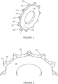
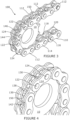
- a drive sprocket according to an embodiment of the first aspect of invention is designated generally by the reference numeral 10.
- Each tooth has a tooth profile defined by a first side 16 comprising a first engagement surface 18, and an opposite second side 20 comprising a second engagement surface 22.
- Each tooth further comprises a front face 24 and a back face 26, the shape of which faces being defined by the first and second sides 18, 20, which in this embodiment comprise first and second engagement surfaces.
- the shape of each face is symmetrical about a radial axis 28 extending along the length of each tooth.
- each side 16, 20 is defined at least partially by an arc. Because each tooth 12 is symmetrical about the axis 28, the dimensions of the arcs forming all sides is the same.
- each arc defining a side of a tooth 12 has a radius of R.
- the centres of the arcs are at a distance x from one another, and at a perpendicular distance y , from the centre of the drive sprocket.
- the centre of each arc is at ⁇ x /2, y .
- Adjacent teeth 12 are separated from one another to define a connecting portion 30, as shown in Figure 2 , for example.
- the connecting portion is substantially flat.
- the connecting portion may not be flat, or there may not be a connecting portion at all.
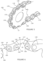
- the power transmission chain 110 comprises a plurality of engagement pockets 150 extending along the chain 110.
- Each engagement pocket 150 comprises a first engaging surface 152, and a second engaging surface 154 which is spaced apart from the first engaging surface 152.
- the first and second engaging surfaces 152, 154 together form an engaging surface pair 156.
- first primary links 114 which are co-planar with one another
- second primary links 116 which are co-planar with one another
- third primary links 118 which are co-planar with one another
- fourth primary links 120 which are also co-planar with one another.
- Each set of primary links is substantially parallel with each other set of primary links.
- the primary links 112 in a particular set, which are co-planar to one another, are also pivotally connected to one another.
- Each primary link 112 has a first pivot point 122, and a second pivot point 124, the first and second pivot points 122 and 124 being spaced apart from one another along each primary link 112, such that adjacent primary links 112 are pivotable about the first and second primary pivot points 122, 124.
- first 114 and second 116 primary links are connected to and abut one another such that the first pivot point 122 of a first primary link 114 is coaxial with the second pivot point 124 of a second primary link 116, and vice versa.
- third 118 and fourth 120 primary links are connected to and abut one another such that the first pivot point 122 of a third primary link 118 is coaxial with the second pivot point 124 of a fourth primary link 120, and vice versa.
- the power transmission chain 110 further comprises a plurality of secondary links 130 each of which secondary links is adapted to rotate substantially about the rotational axis 158 of the respective engagement pocket 150.
- Each secondary link 130 is positioned to be substantially parallel with a respective primary link 112 such that the rotational axis 158 of a particular engagement pocket 150 is coaxial with the first 122, or second 124, pivot points of the corresponding primary links 112. This in turn means that adjacent primary links 112 are pivotable about the axis of rotation 158.
- the plurality of secondary links 132 comprises a plurality of first secondary links 138, and a plurality of second secondary links 140.
- Each first secondary link 138 abuts a second primary link 116
- each second secondary link 140 abuts a third primary link 118.
- first secondary links 138 abut each second primary link 116
- second secondary links 140 abut each third primary link 118.
- first secondary links 138 are substantially coplanar with one another, and the second secondary links 140 are substantially coplanar with one another, the first secondary links 138 are spaced apart from the second secondary links 140 such that each first secondary link 138 faces a corresponding second secondary link 140 to form a pair of secondary links 142.
- each engagement pocket 150 comprises first and second transverse members 144, 146, which are spaced apart from one another and on which the first and second engaging surfaces 152, 154 respectively, are formed.
- the first and second transverse members 144, 146 extend transversely between the corresponding first and second secondary links forming the pair.
- the transverse members 144, 146 thus connect the secondary links together.
- the first and second transverse members 144, 146 each comprise a roller 148.
- each transverse member 144, 146 may comprise a pin.
- the space defined between the first and second transverse members of a secondary link forms an engagement pocket 150.
- the engagement pockets 150 are shaped and positioned to receive and engage with a tooth 12 of the sprocket 10, as shown in the Figures.
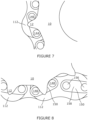
- a tooth 12 of the drive sprocket 10 will mesh to the engagement pocket 150 at a first contact location 160 on the first engagement surface 18 and also at a second contact location 162 on the second engagement surface 20, as shown in Figure 6 , for example.
- the first contact location 160 will engage with the first engaging surface 152 of the engagement pocket 150
- the second contact location 162 will engage with the second engaging surface 154 of the engagement pocket 150.
- the first contact location 160 is radially offset from the second contact location 162.
- rollers 148 This in turn results in the rollers 148 maintaining contact with the first and second engagement surfaces 18, 20 of each corresponding tooth 12, and each secondary link 130 sitting at an offset angle such that one roller 148 sits radially higher on one side the tooth 12 than the roller 148 on the other side of the tooth.
- first and second p pivot points 122, 124 of a primary link 112 is p
- the distance between the axes of first and second transverse members 144, 146 is p 2
- the radius of each roller 148 is r.
- straight lines of length l extend above the tooth from the ends of the arcs towards the centreline at an angle, ⁇ , relative to the tooth centreline such that as the chain wears, causing the pitch, p , of the chain to elongate and the corresponding pitch circle radius, r p , to increase:
- Equations 1 & 2 below give ⁇ , the angle of articulation, and r p , the pitch circle radius, for an n-toothed sprocket of pitch p .
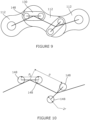
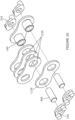
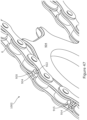
- a power transmission drive member according to an embodiment of the invention is designated generally by the reference numeral 100.
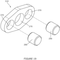
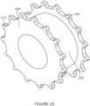
- the drive member 100 is shown articulating around a drive sprocket 200, shown in more detail in Figure 20 .
- sprocket 200 comprises a first set of teeth 210 and a second set of teeth 220.
- the sets of teeth 210, 220 are spaced apart from one another by the sprocket body 230.
- the drive sprocket 200 may be replaced by two separate sprockets each having a single set of teeth and spaced apart from one another so that the teeth of both sprockets engage with the drive member.
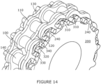
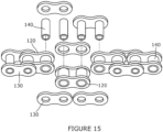
- the drive member comprises a hollow pin bush chain 110 comprising inner links 120 and outer links 130, the links 120, 130 being connected together by hollow pins 140 as shown particularly in Figures 15 and 16 , for example.
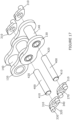
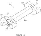
- the drive member 100 further comprises engaging mechanisms 300, as shown particularly in Figure 18 .
- each engaging mechanism comprises two engaging bodies 310.
- Each of the engaging bodies 310 comprises an engagement pocket 320 adapted to engage with the drive sprocket 200.
- Each engagement pocket comprises a first engaging surface 330 and a second engaging surface 340 spaced apart from the first engaging surface 330. Together the first and second engaging surfaces 330, 340 form an engaging surface pair 350 which is rotatable about an engaging mechanism rotational axis shown by the dotted line 360 in Figure 18 .
- each tooth 240 of the drive sprocket 200 will engage with an engaging body 310 by contacting both the first engaging surface 330 and the second engaging surface 340 of the engaging body 310.
- the engaging mechanisms 300 are adapted to engage with each tooth 240 of the sprocket 200 using the principle of dual engagement, whereby contact is made on both sides of each tooth 240 to enable a secure engagement that is energetically efficient and able to distribute the load of the chain over a larger number of teeth of the sprocket 200.
- the first and second engaging surfaces 330, 340 are configured such that when driven, a tooth 240 of the sprocket 200 meshes to the engagement pocket 320 of an engaging mechanism 300 at a first contact location 250 on the first engaging surface 330, and also at a second contact location 260 on the second engaging surface 340.
- the first contact location 250 is radially offset from the second contact location 260. This helps to prevent the engagement pockets 320 from becoming wedged or stuck on a tooth 240 during use.
- first and second engaging surfaces 330, 340 are formed on first and second pins 280, 290 respectively.
- the pins 280, 290 may be integrally formed with the remainder of the engagement body 310.
- the aperture 270 is profiled. This may aid orientation of the engaging body 310 relative to the connecting member 400.
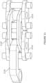
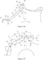
- the power transmission drive member 1100 comprises a hollow pin chain 1110 which is narrower than a conventional hollow pin chain of the type shown in Figure 34 for example.
- the chain 1110 comprises inner links 1120, and outer links 1130 which are similar to the links 110 and 120 of the chain 110 of Figure 3 , except that the width of the chain 1110 no longer has to be wide enough to accommodate sprocket teeth. This is because the teeth 1240 of sprocket 1200 engage externally of the chain 1110 in the same way as described herein above with respect to the embodiment illustrated in Figures 14 to 20 .
- the space between the two sets of teeth of sprocket 1200 is correspondingly narrower than the space between the two sets of teeth of sprocket 200.
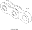
- FIG. 26 a further embodiment of the invention is shown.
- the inner link 1135 has been replaced by a plurality of thinner link plates 1235 forming a composite inner link.
- This can be advantageous from a manufacturing point of view, and also means that by having a plurality of link plates 1235, the thickness of the composite link can be varied according to suit the application.
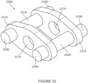
- each engaging mechanism 2300 comprises two engaging bodies 2310 which are spaced apart from one another.
- Each engaging mechanism further comprises first and second extension members 2500, 2510, which extend through each engaging body and serve to connect two engaging bodies 2310 to one another.
- Each extension member 2500, 2510 extends through the engaging bodies 2310 to form pins 2280, 2290 on which the first and second engaging surfaces 2330, 2340 are formed.
- the first and second engaging surfaces of both engaging bodies 2310 are thus integrally formed.
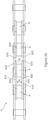
- the drive member 2100 comprises a chain 2110, part of which is shown particularly in Figure 30 .
- the chain comprises outer links 2120, and inner links 2130 connected together by a hollow pin 2140.
- Each link 2120, 2130 comprises a body portion 2520, and first and second legs 2530, 2540 integrally formed with the body portion 2520, and extend from the body portion 2520 to define a space 2550 between the legs 2530, 2540 and the body portion 2520.
- Each leg 2530, 2540 comprises a hollow pin receiving portion 2560, and each link 2120, 2130 is positionable on the engaging bodies 2310 such that the hollow pin receiving portion 2560 of a first leg 2530 of a link is coaxial with the rotational axis of a first engaging mechanism, and the hollow pin receiving portion 2560 of the second leg of the link is coaxial with the rotational axis of a second, adjacent engaging mechanism. This means that the hollow pin receiving portions 2560 are coaxial with the apertures 2270 of the engaging bodies 2310.
- Each engaging mechanism 2300 further comprises a central pin 2570 which passes through a respective hollow pin 2140.
- Each hollow pin 2140 fits through the hollow pin receiving portion 2560 of a respective inner link 2130.
- the central pin 2570 extends through the hollow pin 2140 and the respective apertures 2270 of both engaging bodies 2310, with the engaging bodies 2310 positioned on either side of the outer link 2120.
- the space 2550 provides space for the rotation.
- the engaging mechanism 2300 and the engaging bodies 2310 are equivalent to the engaging mechanism 300 and the engaging bodies 310 and function in the same way.
- the first and second engaging surfaces 2330, 2340 form an engagement pocket 2320 which is equivalent to engagement pocket 320 and therefore results in dual engagement of the tooth of a sprocket in the pitch pocket as described with reference to the previous embodiment.
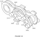
- FIG. 33 a further embodiment of an outer link plate 3120 is shown including angle of rotation limiters. These limiters are designed to prevent over rotation of the engaging bodies during use.
- the outer link plate 3120 comprises limiters 3600 formed from bent sections of the outer link plate 3120.
- the angle limiters 3600 limit the rotational movement of the engaging bodies 3310 and thus reduce the likelihood that the engaging bodies will become stuck.
- each tooth of a drive sprocket will engage with an engaging body by contacting both a first engaging surface and a second engaging surface.
- This dual engagement reduces the stress on the sprocket as well as relative movement between the chain and sprocket during use thereby reducing wear and tear on the drive member as well as the drive sprocket.
- frictional losses are reduced, thereby increasing transmission efficiency.
- the transmission system comprises a sprocket 4 and a drive member comprising a roller chain 6.
- the roller chain 6 is a standard roller chain comprising a plurality of rollers 8 which extend transversely across the transmission member and are spaced apart along the length of the drive member to form the chain.
- the rollers are connected to one another by links 10 in a known manner.
- the roller chain 6 is able to articulate between adjacent rollers 8.
- An engagement pocket 40 is defined between adjacent rollers 8. Each engagement pocket 40 is adapted to engage with a tooth 12 as will be described in more detail below.
- every other engagement pocket 40 will engage with a tooth during use of the transmission system 2.
- the remaining every other engagement pockets 40 will effectively engage with the space between adjacent teeth 12.
- the sprocket 4 comprises a plurality of teeth 12 which are all shaped substantially identically to one another. Each tooth has a tooth face or profile 14 which is symmetrical about a radial axis R of the sprocket 4.
- the tooth profile 14 is defined by a first side 16 comprising a first engagement surface 18, and a second side 20 defining a second engagement surface 22.
- Each of the first and second sides 16,20 comprises a base portion 24 which forms a roller seating curve 25.
- Each side further comprises a portion 26 extending from the roller seating curve towards a tip 28 of the tooth. The portion 26 is convex and defines a working curve 29.
- the sprocket 4 comprises a further curve 30 forming a supporting curve 31 which extends between adjacent teeth.
- every other engagement pocket 40 will engage with a respective tooth 12 whilst the remaining every other engagement pocket 40 will not engage a tooth. This is because, due to the dimensions of the sprocket, and particularly the profile of the tooth, relative to the dimensions of the rollers 8, when the roller chain 6 is engaged with the sprocket 4 there will be two rollers 8 positioned between adjacent teeth. This in turn means that every other engagement pocket 40 will engage with a tooth 12, with every other engagement pocket effectively engaging with spaces between adjacent teeth 12 of the sprocket.
- one roller 32 When considering a pair of rollers 8 positioned on either side of a tooth 12, one roller 32 will be a load bearing roller, and the second roller 8 will be a supporting roller 34.
- the roller seating curve 25 provides an initial seating position for the engaged rollers 8 of the roller chain 6. For both load bearing and supporting rollers, this curve helps to distribute the contact load over a larger area reducing material stresses, at least initially when the chain wear is low.
- the roller seating curve 25 enables rollers to easily transition between supporting and load bearing positions if the drive direction is ever reversed.
- the load bearing roller 32 will engage with the tooth 12 on a first engagement surface 36, and the support roller 34 will engage with the tooth at a second engagement surface 38.
- the first and second engagement surfaces 36,38 are radially offset from one another. This enables the pair of rollers 8 engaging the tooth 12 to engage with dual engagement, since the roller chain makes contact with the sprocket teeth 12 at two contact points 37, 39 on engagement surfaces 36, 38 in each tooth of the sprocket.
- the two contact points 37, 39 are thus on opposing sides of the tooth relative to its radial centreline R, and are radially offset from one another and therefore not symmetric relative to the radial centreline R.
- the first contact point 37 is load bearing and transfers the load between the roller chain 6 and the tooth 12.
- the second contact point 39 is supporting and thus stabilises the roller chain 6 on the sprocket 4 and increases the load distribution over the sprocket teeth 12.
- the working curve 26 is convex, and the convex arc forming the working curve 26 curves towards the tooth centreline R.
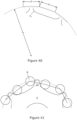
- the surface of working curve 26 makes contact with the load bearing roller 32, enabling torque transfer between the roller chain 6 and the sprocket 4. As the chain pitch elongates due to internal wear, this surface also accommodates the climbing of the load-bearing roller as shown in Figure 40 .
- the working curve is the primary load bearing contact surface situated on an upper portion of the sides of each tooth. It is this surface that makes contact with the load bearing roller 32, enabling torque transfer between chain and sprocket. As the chain pitch elongates due to internal wear, this surface also accommodates the climbing of the load bearing roller ensuring that the sprocket is able to transfer load through the entire lifetime of the chain.
- the supporting curve is designed to accommodate the supporting roller 34.
- the supporting curve may also accommodate some movement of the supporting roller 34 over the lifetime of the roller chain 6, as the worn chain adopts an altered position on the sprocket.
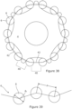
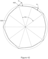
- the engaging pockets 40 are represented by lines 42.
- the line 42 of each engagement pocket sits with endpoints situated on a circle 44 known as the pitch circle.
- the pitch circle defines the centre point of all the roller seating curves 25.
- each roller seating curve is slightly larger than the radius of each roller. This results in the engagement pockets 40 sitting marginally off the pitch circle 44. This in turn ensures that the rollers adopt their respective load bearing and supporting positions and prevents the engagement pockets from getting stuck on the teeth.
- the distance between adjacent rollers may be represented by the letter p
- the diameter of each roller may be represented by d r .
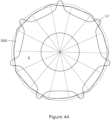
- FIG 40 a schematic representation of part of the transmission system 2 of Figure 34 is shown.
- the circle radius r p represents the pitch circle. This is the circle which passes through all of vertices of a regular polygon of n sides, for a sprocket 4 which has n/2 teeth. Each side of the regular polygon has a length ⁇ .
- Figure 40 shows three of the sides of the regular polygon showing the length as ⁇ .
- the radius of the arc forming the first face arc and the second face arc may be represented by r s .
- the centre of a roller seating curve 25 with radius r s sits at each vertex of the regular polygon forming the bases of the teeth.
- the radius of the arc may be compared with the radius of the roller and given as a ratio ⁇ .
- the steepness of the working curve relative to the centreline of the tooth at the contact point of the load bearing roller 32 may be denoted by ⁇ .
- the ratio ⁇ was found to be 1.01 regardless of the number of teeth on the sprocket 12.
- ⁇ was found to vary depending on the number of teeth forming the sprocket.
- the teeth 12 of the sprocket 4 will have a profile that hardly varies depending on the number of teeth forming the sprocket.
- a standard roller chain for example a roller chain meeting the ISO 606 standard, is able to engage a sprocket such that dual engagement is achieved.
- the roller seating arc has a fixed radius r s for all n, and this radius is slightly larger than the radius of each roller 8.
- a transmission system according to an embodiment of the invention is designated generally by the reference numeral 2.
- the transmission system comprises a sprocket 4 and a drive member comprising a roller chain 6.
- the roller chain 6 is a standard roller chain comprising a plurality of rollers 8 which extend transversely across the transmission member and are spaced apart along the length of the drive member to form the chain.
- the rollers are connected to one another by links 10 in a known manner.
- the roller chain 6 is able to articulate between adjacent rollers 8.
- An engagement pocket 40 is defined between adjacent rollers 8. Each engagement pocket 40 is adapted to engage with a tooth 12 as will be described in more detail below.
- every other engagement pocket 40 will engage with a tooth during use of the transmission system 2.
- the remaining every other engagement pockets 40 will effectively engage with the space between adjacent teeth 12.
- the sprocket 4 comprises a plurality of teeth 12 which are all shaped substantially identically to one another. Each tooth has a tooth face or profile 14 which is symmetrical about a radial axis R of the sprocket 4.
- the tooth profile 14 is defined by a first side 16 comprising a first engagement surface 18, and a second side 20 defining a second engagement surface 22.
- Each of the first and second sides 16,20 comprises a base portion 24 which forms a roller seating curve 25.
- Each side further comprises a portion 26 extending from the roller seating curve towards a tip 28 of the tooth. The portion 26 is convex and defines a working curve 29.
- the sprocket 4 comprises a further curve 30 forming a supporting curve 31 which extends between adjacent teeth.
- every other engagement pocket 40 will engage with a respective tooth 12 whilst the remaining every other engagement pocket 40 will not engage a tooth. This is because, due to the dimensions of the sprocket, and particularly the profile of the tooth, relative to the dimensions of the rollers 8, when the roller chain 6 is engaged with the sprocket 4 there will be two rollers 8 positioned between adjacent teeth. This in turn means that every other engagement pocket 40 will engage with a tooth 12, with every other engagement pocket effectively engaging with spaces between adjacent teeth 12 of the sprocket.
- one roller 32 When considering a pair of rollers 8 positioned on either side of a tooth 12, one roller 32 will be a load bearing roller, and the second roller 8 will be a supporting roller 34.
- the roller seating curve 25 provides an initial seating position for the engaged rollers 8 of the roller chain 6. For both load bearing and supporting rollers, this curve helps to distribute the contact load over a larger area reducing material stresses, at least initially when the chain wear is low.
- the roller seating curve 25 enables rollers to easily transition between supporting and load bearing positions if the drive direction is ever reversed.
- the load bearing roller 32 will engage with the tooth 12 on a first engagement surface 36, and the support roller 34 will engage with the tooth at a second engagement surface 38.
- the first and second engagement surfaces 36,38 are radially offset from one another. This enables the pair of rollers 8 engaging the tooth 12 to engage with dual engagement, since the roller chain makes contact with the sprocket teeth 12 at two contact points 37, 39 on engagement surfaces 36, 38 in each tooth of the sprocket.
- the two contact points 37, 39 are thus on opposing sides of the tooth relative to its radial centreline R, and are radially offset from one another and therefore not symmetric relative to the radial centreline R.
- the first contact point 37 is load bearing and transfers the load between the roller chain 6 and the tooth 12.
- the second contact point 39 is supporting and thus stabilises the roller chain 6 on the sprocket 4 and increases the load distribution over the sprocket teeth 12.
- each tooth 12 further comprises a working curve 26 that extends from the roller seating curve towards the tip 28 of the tooth.
- the working curve 26 is convex, and the convex arc forming the working curve 26 curves towards the tooth centreline R.
- the surface of working curve 26 makes contact with the load bearing roller 32, enabling torque transfer between the roller chain 6 and the sprocket 4. As the chain pitch elongates due to internal wear, this surface also accommodates the climbing of the load-bearing roller.
- the sprocket further comprises a supporting curve 50 which extends between the roller seating curves of adjacent teeth.
- rollers 8 of the roller chain 6 are able to articulate relative to one another via the links connecting adjacent rollers to one another.
- First roller 32 and second roller 34 are shown forming a first engagement pocket 401 which meshes with a first tooth 112.
- a third roller 322 is in contact with a second tooth 212 and is positioned to one side of the first roller 32.
- the third roller 322 and the first roller 32 together form a second engagement pocket 402.
- a fourth roller 422 is positioned adjacent to second roller 34 and is in contact with a third tooth 312.
- the second and fourth rollers 34, 422 together form a third engagement pocket 403.
- the first roller 32 is a load bearing roller
- the second roller 34 is a support roller. Every other roller starting with the load bearing roller 32 will also be a load bearing roller.
- the fourth roller 422 is also a load bearing roller. This pattern will repeat itself around the sprocket 4.
- first roller 32 makes contact with first tooth 112
- third roller 322 is also in contact with a second tooth 212
- first roller 32 and third roller 322 are positioned on their respective engagement surfaces, and the second roller 34 is in position
- a first articulation angle a 1 is formed at an articulation point 400, which in this embodiment coincides with the axis of the first roller 32.
- the second articulation angle a 2 is formed at the second roller 34 when the second roller 34 and the fourth roller 422 are in contact with a respective tooth 12, and the first roller 322 is in contact with tooth 112.
- the magnitude of the first articulation angle a 1 at the point defined above is in this example greater than the second articulation angle a 2 at the point defined above.
- every other roller starting with the second roller 34 is a support roller.
- the third roller 322 is also a support roller and this pattern will repeat itself around the sprocket 4.
- every other articulation angle will be the same. This means that the articulation angle a 1 will be at every load bearing roller, and the articulation angle a 2 will be at every support roller.
- Adjacent rollers are connected to one another by a link which provides a rigid connection between adjacent rollers.
- first roller 32 is connected to second roller 34 by link 450.
- Third roller 322 is connected to first roller 32 by link 452, and second roller 34 is connected to fourth roller 422 by link 454.
- each load bearing roller 332 will articulate for a longer duration than is the case with each support roller 34. This can improve the efficiency of the transmission system.
- the losses associated with each articulation alternates with the alternating inner and outer chain links of a standard power transmission roller chain.
- the articulation of the outer link is more efficient than the inner, while the articulation of the inner link leads to less chain elongation than the outer.
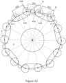
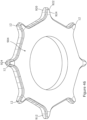
- the articulation points 400 in a transmission system define a n sided irregular polygon 500.
- the pattern is repeated for every pair of links around the sprocket circumference.
- a sprocket 904 according to another embodiment of the invention is illustrated schematically.
- the sprocket 904 forms part of a transmission system 1002 comprising the sprocket 904 and a roller chain 6.
- the roller chain 6 comprises a plurality of rollers 8.
- the rollers 8 are connected to adjacent rollers by means of inner links 810 and outer links 820.
- the inner links 810 serve to connect two rollers 8 together to form a roller pair 850.
- the outer links serve to connect roller pairs 850 together to form the roller chain 6.
- the distance between inner surfaces 860 of inner links 810 is indicated by the reference numeral d 1 in Figure 45 .
- the distance between inner surfaces 870 of facing outer links 820 is indicated by the reference numeral d 2 . As shown in Figure 45 , d 2 is greater than d 1 .
- the sprocket comprises a plurality of teeth 12 spaced apart around the sprocket. Each tooth has a first width 914 that is equal to or slightly less than the distance between inner surfaces of facing inner links 800 (d 1 ).
- Each tooth 12 also has a second width 915 which is equal to or slightly less than the distance between the inner surfaces 870 of outer links 820 (d 2 ).
- each tooth comprises a middle tooth portion 920 and outer tooth portions 922, 924 which together define the second width.
- the teeth When the sprocket 904 engages with the roller chain 6, the teeth will be positioned between two outer links as shown in Figure 47 .
- the width of the outer tooth portions 922, 924 together with the width of the middle portion 920 results in an overall tooth width that is the same as or slightly less than the distance (d 2 ) between inner surfaces of facing outer links, and greater than the distance (d 1 ) between the inner surfaces of facing inner links. This means that the fit between the tooth 12 and the chain 6 is such that there is little clearance between the tooth and the chain.
- the presence of the outer tooth portions 922, 924 prevents the teeth from engaging between inner links, and thus the alignment of the chain is substantially maintained during use of the drive transmission system.
- the middle portion 920 prevents the inner links from interfering with the tooth during use.
Landscapes
- Engineering & Computer Science (AREA)
- General Engineering & Computer Science (AREA)
- Mechanical Engineering (AREA)
- Gears, Cams (AREA)
- Devices For Conveying Motion By Means Of Endless Flexible Members (AREA)
- Vehicle Body Suspensions (AREA)
Applications Claiming Priority (5)
| Application Number | Priority Date | Filing Date | Title |
|---|---|---|---|
| GB2011083.9A GB2597910B (en) | 2020-07-17 | 2020-07-17 | Drive sprocket |
| GB2018496.6A GB2597338B (en) | 2020-07-17 | 2020-11-25 | Power transmission drive member |
| GB2102302.3A GB2597345B (en) | 2020-07-17 | 2021-02-18 | Drive sprocket |
| GB2108320.9A GB2597593B (en) | 2020-07-17 | 2021-06-10 | Transmission system |
| PCT/GB2021/051787 WO2022013538A1 (en) | 2020-07-17 | 2021-07-13 | Transmission system |
Publications (3)
| Publication Number | Publication Date |
|---|---|
| EP4182579A1 EP4182579A1 (en) | 2023-05-24 |
| EP4182579B1 true EP4182579B1 (en) | 2025-03-12 |
| EP4182579C0 EP4182579C0 (en) | 2025-03-12 |
Family
ID=72338842
Family Applications (1)
| Application Number | Title | Priority Date | Filing Date |
|---|---|---|---|
| EP21746128.4A Active EP4182579B1 (en) | 2020-07-17 | 2021-07-13 | Transmission system |
Country Status (12)
| Country | Link |
|---|---|
| EP (1) | EP4182579B1 (pl) |
| JP (1) | JP7751627B2 (pl) |
| KR (1) | KR20230095914A (pl) |
| CN (1) | CN116113779A (pl) |
| AU (1) | AU2021307126A1 (pl) |
| CA (1) | CA3185699A1 (pl) |
| ES (1) | ES3030515T3 (pl) |
| GB (4) | GB2597910B (pl) |
| HU (1) | HUE071796T2 (pl) |
| PL (1) | PL4182579T3 (pl) |
| WO (1) | WO2022013538A1 (pl) |
| ZA (1) | ZA202300356B (pl) |
Families Citing this family (1)
| Publication number | Priority date | Publication date | Assignee | Title |
|---|---|---|---|---|
| EP4343231A4 (en) * | 2021-11-19 | 2024-12-18 | Samsung Electronics Co., Ltd. | AIR CONDITIONER |
Family Cites Families (7)
| Publication number | Priority date | Publication date | Assignee | Title |
|---|---|---|---|---|
| US2489039A (en) * | 1948-06-14 | 1949-11-22 | Harry Y Law | Chain and sprocket assembly |
| NL9300985A (nl) * | 1993-02-10 | 1994-09-01 | Stork Rms Bv | Instelbaar kettingwiel en onderdelen daarvan. |
| US6761657B2 (en) * | 1996-12-19 | 2004-07-13 | Cloyes Gear And Products, Inc. | Roller chain sprocket with added chordal pitch reduction |
| US5997424A (en) * | 1998-03-26 | 1999-12-07 | Cloyes Gear And Products, Inc. | Random engagement roller chain sprocket with staged meshing and root relief to provide improved noise characteristics |
| JP3212288B2 (ja) * | 1999-03-02 | 2001-09-25 | 三協オイルレス工業株式会社 | チェーン駆動機構装置 |
| JP3904789B2 (ja) * | 2000-01-28 | 2007-04-11 | 本田技研工業株式会社 | チェーン伝動装置 |
| JP7011800B2 (ja) * | 2016-08-05 | 2022-01-27 | 株式会社スギノエンジニアリング | 自転車用ギア板 |
-
2020
- 2020-07-17 GB GB2011083.9A patent/GB2597910B/en active Active
- 2020-11-25 GB GB2018496.6A patent/GB2597338B/en active Active
-
2021
- 2021-02-18 GB GB2102302.3A patent/GB2597345B/en active Active
- 2021-06-10 GB GB2108320.9A patent/GB2597593B/en active Active
- 2021-07-13 AU AU2021307126A patent/AU2021307126A1/en active Pending
- 2021-07-13 PL PL21746128.4T patent/PL4182579T3/pl unknown
- 2021-07-13 ES ES21746128T patent/ES3030515T3/es active Active
- 2021-07-13 JP JP2023501765A patent/JP7751627B2/ja active Active
- 2021-07-13 WO PCT/GB2021/051787 patent/WO2022013538A1/en not_active Ceased
- 2021-07-13 HU HUE21746128A patent/HUE071796T2/hu unknown
- 2021-07-13 CN CN202180057204.7A patent/CN116113779A/zh active Pending
- 2021-07-13 EP EP21746128.4A patent/EP4182579B1/en active Active
- 2021-07-13 CA CA3185699A patent/CA3185699A1/en active Pending
- 2021-07-13 KR KR1020237005623A patent/KR20230095914A/ko active Pending
-
2023
- 2023-01-09 ZA ZA2023/00356A patent/ZA202300356B/en unknown
Also Published As
| Publication number | Publication date |
|---|---|
| WO2022013538A1 (en) | 2022-01-20 |
| JP2023535322A (ja) | 2023-08-17 |
| ES3030515T3 (en) | 2025-06-30 |
| CA3185699A1 (en) | 2022-01-20 |
| GB2597345A (en) | 2022-01-26 |
| GB2597593B (en) | 2023-02-08 |
| KR20230095914A (ko) | 2023-06-29 |
| CN116113779A (zh) | 2023-05-12 |
| GB2597338B (en) | 2022-07-13 |
| GB202018496D0 (en) | 2021-01-06 |
| GB2597910B (en) | 2023-08-16 |
| GB2597338A (en) | 2022-01-26 |
| EP4182579A1 (en) | 2023-05-24 |
| HUE071796T2 (hu) | 2025-09-28 |
| AU2021307126A1 (en) | 2023-02-09 |
| GB202102302D0 (en) | 2021-04-07 |
| JP7751627B2 (ja) | 2025-10-08 |
| GB2597345B (en) | 2023-02-15 |
| GB2597910A (en) | 2022-02-16 |
| EP4182579C0 (en) | 2025-03-12 |
| PL4182579T3 (pl) | 2025-07-07 |
| GB202011083D0 (en) | 2020-09-02 |
| GB202108320D0 (en) | 2021-07-28 |
| GB2597593A (en) | 2022-02-02 |
| ZA202300356B (en) | 2023-09-27 |
Similar Documents
| Publication | Publication Date | Title |
|---|---|---|
| US5372554A (en) | Rocker joint chain with crescent shaped apertures | |
| US5176587A (en) | Single pin rocker joint bushing chain | |
| US5423724A (en) | Interlaced single pin rocker joint chain | |
| JP3784452B2 (ja) | 動力伝達用チェーンのロッカージョイント構造 | |
| EP4182579B1 (en) | Transmission system | |
| EP0877178B1 (en) | Chain assembly using formed bushings with inverted teeth | |
| JP2607890Y2 (ja) | ロッカジョイント | |
| CN101334089B (zh) | 具有非对称渐开线齿形的无声链条 | |
| US11885394B2 (en) | Drive sprocket | |
| US5192253A (en) | Single pin rocker joint chain | |
| US11566697B2 (en) | Drive sprocket | |
| US11603906B2 (en) | Drive sprocket | |
| US4579550A (en) | Chains for continuously variable conical pulley transmissions | |
| US11732782B2 (en) | Transmission system | |
| US11655878B2 (en) | Power transmission drive member | |
| US9476481B2 (en) | Drive chain | |
| US11608874B2 (en) | Rocker joint roller chain |
Legal Events
| Date | Code | Title | Description |
|---|---|---|---|
| STAA | Information on the status of an ep patent application or granted ep patent |
Free format text: STATUS: UNKNOWN |
|
| STAA | Information on the status of an ep patent application or granted ep patent |
Free format text: STATUS: THE INTERNATIONAL PUBLICATION HAS BEEN MADE |
|
| PUAI | Public reference made under article 153(3) epc to a published international application that has entered the european phase |
Free format text: ORIGINAL CODE: 0009012 |
|
| STAA | Information on the status of an ep patent application or granted ep patent |
Free format text: STATUS: REQUEST FOR EXAMINATION WAS MADE |
|
| 17P | Request for examination filed |
Effective date: 20230110 |
|
| AK | Designated contracting states |
Kind code of ref document: A1 Designated state(s): AL AT BE BG CH CY CZ DE DK EE ES FI FR GB GR HR HU IE IS IT LI LT LU LV MC MK MT NL NO PL PT RO RS SE SI SK SM TR |
|
| DAV | Request for validation of the european patent (deleted) | ||
| DAX | Request for extension of the european patent (deleted) | ||
| STAA | Information on the status of an ep patent application or granted ep patent |
Free format text: STATUS: EXAMINATION IS IN PROGRESS |
|
| 17Q | First examination report despatched |
Effective date: 20240125 |
|
| GRAP | Despatch of communication of intention to grant a patent |
Free format text: ORIGINAL CODE: EPIDOSNIGR1 |
|
| STAA | Information on the status of an ep patent application or granted ep patent |
Free format text: STATUS: GRANT OF PATENT IS INTENDED |
|
| INTG | Intention to grant announced |
Effective date: 20241008 |
|
| GRAS | Grant fee paid |
Free format text: ORIGINAL CODE: EPIDOSNIGR3 |
|
| GRAA | (expected) grant |
Free format text: ORIGINAL CODE: 0009210 |
|
| STAA | Information on the status of an ep patent application or granted ep patent |
Free format text: STATUS: THE PATENT HAS BEEN GRANTED |
|
| AK | Designated contracting states |
Kind code of ref document: B1 Designated state(s): AL AT BE BG CH CY CZ DE DK EE ES FI FR GB GR HR HU IE IS IT LI LT LU LV MC MK MT NL NO PL PT RO RS SE SI SK SM TR |
|
| REG | Reference to a national code |
Ref country code: GB Ref legal event code: FG4D |
|
| REG | Reference to a national code |
Ref country code: CH Ref legal event code: EP |
|
| REG | Reference to a national code |
Ref country code: DE Ref legal event code: R096 Ref document number: 602021027536 Country of ref document: DE |
|
| REG | Reference to a national code |
Ref country code: IE Ref legal event code: FG4D |
|
| U01 | Request for unitary effect filed |
Effective date: 20250328 |
|
| U07 | Unitary effect registered |
Designated state(s): AT BE BG DE DK EE FI FR IT LT LU LV MT NL PT RO SE SI Effective date: 20250403 |
|
| REG | Reference to a national code |
Ref country code: ES Ref legal event code: FG2A Ref document number: 3030515 Country of ref document: ES Kind code of ref document: T3 Effective date: 20250630 |
|
| PG25 | Lapsed in a contracting state [announced via postgrant information from national office to epo] |
Ref country code: RS Free format text: LAPSE BECAUSE OF FAILURE TO SUBMIT A TRANSLATION OF THE DESCRIPTION OR TO PAY THE FEE WITHIN THE PRESCRIBED TIME-LIMIT Effective date: 20250612 |
|
| PG25 | Lapsed in a contracting state [announced via postgrant information from national office to epo] |
Ref country code: HR Free format text: LAPSE BECAUSE OF FAILURE TO SUBMIT A TRANSLATION OF THE DESCRIPTION OR TO PAY THE FEE WITHIN THE PRESCRIBED TIME-LIMIT Effective date: 20250312 |
|
| PGFP | Annual fee paid to national office [announced via postgrant information from national office to epo] |
Ref country code: HU Payment date: 20250708 Year of fee payment: 5 |
|
| REG | Reference to a national code |
Ref country code: SK Ref legal event code: T3 Ref document number: E 46560 Country of ref document: SK |
|
| U20 | Renewal fee for the european patent with unitary effect paid |
Year of fee payment: 5 Effective date: 20250711 |
|
| REG | Reference to a national code |
Ref country code: GR Ref legal event code: EP Ref document number: 20250401152 Country of ref document: GR Effective date: 20250707 |
|
| REG | Reference to a national code |
Ref country code: HU Ref legal event code: AG4A Ref document number: E071796 Country of ref document: HU |
|
| PG25 | Lapsed in a contracting state [announced via postgrant information from national office to epo] |
Ref country code: SM Free format text: LAPSE BECAUSE OF FAILURE TO SUBMIT A TRANSLATION OF THE DESCRIPTION OR TO PAY THE FEE WITHIN THE PRESCRIBED TIME-LIMIT Effective date: 20250312 |
|
| PGFP | Annual fee paid to national office [announced via postgrant information from national office to epo] |
Ref country code: GR Payment date: 20250716 Year of fee payment: 5 Ref country code: NO Payment date: 20250724 Year of fee payment: 5 |
|
| PGFP | Annual fee paid to national office [announced via postgrant information from national office to epo] |
Ref country code: TR Payment date: 20250702 Year of fee payment: 5 Ref country code: PL Payment date: 20250704 Year of fee payment: 5 |
|
| PGFP | Annual fee paid to national office [announced via postgrant information from national office to epo] |
Ref country code: GB Payment date: 20250710 Year of fee payment: 5 |
|
| PGFP | Annual fee paid to national office [announced via postgrant information from national office to epo] |
Ref country code: CH Payment date: 20250801 Year of fee payment: 5 |
|
| PG25 | Lapsed in a contracting state [announced via postgrant information from national office to epo] |
Ref country code: CZ Free format text: LAPSE BECAUSE OF FAILURE TO SUBMIT A TRANSLATION OF THE DESCRIPTION OR TO PAY THE FEE WITHIN THE PRESCRIBED TIME-LIMIT Effective date: 20250312 |
|
| PGFP | Annual fee paid to national office [announced via postgrant information from national office to epo] |
Ref country code: IE Payment date: 20250710 Year of fee payment: 5 |
|
| PGFP | Annual fee paid to national office [announced via postgrant information from national office to epo] |
Ref country code: SK Payment date: 20250701 Year of fee payment: 5 |
|
| PG25 | Lapsed in a contracting state [announced via postgrant information from national office to epo] |
Ref country code: IS Free format text: LAPSE BECAUSE OF FAILURE TO SUBMIT A TRANSLATION OF THE DESCRIPTION OR TO PAY THE FEE WITHIN THE PRESCRIBED TIME-LIMIT Effective date: 20250712 |