EP4180822B1 - Pipettiereinheit - Google Patents
Pipettiereinheit Download PDFInfo
- Publication number
- EP4180822B1 EP4180822B1 EP22202366.5A EP22202366A EP4180822B1 EP 4180822 B1 EP4180822 B1 EP 4180822B1 EP 22202366 A EP22202366 A EP 22202366A EP 4180822 B1 EP4180822 B1 EP 4180822B1
- Authority
- EP
- European Patent Office
- Prior art keywords
- drive
- shaft
- housing
- pipetting
- gear wheel
- Prior art date
- Legal status (The legal status is an assumption and is not a legal conclusion. Google has not performed a legal analysis and makes no representation as to the accuracy of the status listed.)
- Active
Links
Images


Classifications
-
- B—PERFORMING OPERATIONS; TRANSPORTING
- B01—PHYSICAL OR CHEMICAL PROCESSES OR APPARATUS IN GENERAL
- B01L—CHEMICAL OR PHYSICAL LABORATORY APPARATUS FOR GENERAL USE
- B01L3/00—Containers or dishes for laboratory use, e.g. laboratory glassware; Droppers
- B01L3/02—Burettes; Pipettes
- B01L3/021—Pipettes, i.e. with only one conduit for withdrawing and redistributing liquids
-
- G—PHYSICS
- G01—MEASURING; TESTING
- G01N—INVESTIGATING OR ANALYSING MATERIALS BY DETERMINING THEIR CHEMICAL OR PHYSICAL PROPERTIES
- G01N35/00—Automatic analysis not limited to methods or materials provided for in any single one of groups G01N1/00 - G01N33/00; Handling materials therefor
- G01N35/10—Devices for transferring samples or any liquids to, in, or from, the analysis apparatus, e.g. suction devices, injection devices
- G01N35/1065—Multiple transfer devices
- G01N35/1067—Multiple transfer devices for transfer to or from containers having different spacing
-
- G—PHYSICS
- G01—MEASURING; TESTING
- G01N—INVESTIGATING OR ANALYSING MATERIALS BY DETERMINING THEIR CHEMICAL OR PHYSICAL PROPERTIES
- G01N35/00—Automatic analysis not limited to methods or materials provided for in any single one of groups G01N1/00 - G01N33/00; Handling materials therefor
- G01N35/10—Devices for transferring samples or any liquids to, in, or from, the analysis apparatus, e.g. suction devices, injection devices
- G01N35/1009—Characterised by arrangements for controlling the aspiration or dispense of liquids
- G01N35/1011—Control of the position or alignment of the transfer device
-
- G—PHYSICS
- G01—MEASURING; TESTING
- G01N—INVESTIGATING OR ANALYSING MATERIALS BY DETERMINING THEIR CHEMICAL OR PHYSICAL PROPERTIES
- G01N35/00—Automatic analysis not limited to methods or materials provided for in any single one of groups G01N1/00 - G01N33/00; Handling materials therefor
- G01N35/10—Devices for transferring samples or any liquids to, in, or from, the analysis apparatus, e.g. suction devices, injection devices
- G01N35/1065—Multiple transfer devices
- G01N35/1072—Multiple transfer devices with provision for selective pipetting of individual channels
-
- G—PHYSICS
- G01—MEASURING; TESTING
- G01N—INVESTIGATING OR ANALYSING MATERIALS BY DETERMINING THEIR CHEMICAL OR PHYSICAL PROPERTIES
- G01N35/00—Automatic analysis not limited to methods or materials provided for in any single one of groups G01N1/00 - G01N33/00; Handling materials therefor
- G01N35/10—Devices for transferring samples or any liquids to, in, or from, the analysis apparatus, e.g. suction devices, injection devices
- G01N35/1065—Multiple transfer devices
- G01N35/1067—Multiple transfer devices for transfer to or from containers having different spacing
- G01N2035/1069—Multiple transfer devices for transfer to or from containers having different spacing by adjusting the spacing between multiple probes of a single transferring head
-
- G—PHYSICS
- G01—MEASURING; TESTING
- G01N—INVESTIGATING OR ANALYSING MATERIALS BY DETERMINING THEIR CHEMICAL OR PHYSICAL PROPERTIES
- G01N35/00—Automatic analysis not limited to methods or materials provided for in any single one of groups G01N1/00 - G01N33/00; Handling materials therefor
- G01N35/10—Devices for transferring samples or any liquids to, in, or from, the analysis apparatus, e.g. suction devices, injection devices
- G01N35/1065—Multiple transfer devices
- G01N2035/1076—Multiple transfer devices plurality or independently movable heads
Definitions
- the invention relates to a pipetting unit and a system for handling liquids comprising said pipetting unit.
- Automated analyser systems for use in clinical diagnostics and life sciences are produced by a number of companies.
- STRATEC ® SE Birkenfeld, Germany
- Such analyzer systems usually have a liquid handling device, which comprises a pipetting device for aspirating or dispensing liquids in receptacles like multi well plates which are flat plates having a plurality of wells for taking up or providing a liquid.
- multi-needle pipettors are often used to increase the throughput of samples to be analysed by pipetting in parallel from or into multiple wells.
- the pipetting units are usually arranged offset for multi-needle pipetting to be able to realise a pipetting distance of 9 mm.
- Powerful drives with encoders which are required to drive the pipetting units in the Y and Z directions, can be located at the top or bottom of the pipetting units.
- the arrangement depends on the respective positioning in the multi-needle pipetting unit. This nested structure results in different pipetting units that cannot be positioned arbitrarily in relation to each other.
- the Z-axis of a pipetting unit dips through the neighbouring pipetting unit. Removal of individual pipetting units is only possible with difficulty and represents a considerable effort in the service case.
- US 2016/266162 A1 discloses a pipetting workstation comprising a pipetting mechanism bracket and a plurality of pipetting mechanisms; wherein, the pipetting mechanism comprises a mobile seat, a mobile rod movably mounted on the mobile seat; a mobile rod drive mechanism; a gear capable of turning around the vertical direction; a linear rail fastening seat; and a pipette disposed at the lower end of the mobile rod.
- US 2016/266162 A further discloses the abovementioned pipetting mechanism and provides usage of the pipetting workstation in such aspects as liquid sample dosing and liquid transferring.
- the pipetting mechanism used in the pipetting workstation provided US 2016/266162 A can independently make vertical or horizontal movements, and does not require or reduces lubricating services, which accordingly avoid contamination.
- a device for aspirating and dispensing more than one liquid sample comprising - a main frame body - more than one pipetting units, said pipetting units extending side by side in parallel with each other; wherein a pipetting unit comprises - an interface for interacting with an interface of a pipette tip, - a first module for aspirating and dispensing a liquid, - a second module for Y-axis movement, and third module for Z-Axis movement, wherein said second and third modules are function independently; - a fourth module for controlling functions of said pipette unit - two frames for receiving at least one of said modules, wherein said at least one module is mounted in one of said frames, - an X-transfer mechanism connected to said main frame body to which said pipetting units are connected; wherein said at least one module of one pipette unit is mounted in one of said two frames, and said at least one module of the adjacent pipette units are mounted in the
- the magnetic angle sensor device includes a shaft rotatable around a rotation axis; a magnetic field source coupled to the shaft; a first magnetic angle sensor configured to generate a first signal that represents a first angle based on a first diametric magnetic field from the magnetic field source applied to the first magnetic angle sensor; a second magnetic angle sensor configured to generate a second signal that represents a second angle based on a second diametric magnetic field from the magnetic field source applied to the second magnetic angle sensor; and a combining circuit configured to determine a combined rotation angle based on the first signal and on the second signal.
- a cannula which is secured within a first gear rack is driven upwardly and downwardly within the housing by the first gearwheel which is driven by the drive shaft.
- the clutch decouples the second gearwheel from the first gearwheel so that the cannula is urgeable through the closure cap into the vial for withdrawing the liquid sample.
- the clutch retains the second gearwheel decoupled from the first gearwheel until the cannula has been withdrawn from the closure cap to prevent displacement of the closure cap during withdrawal of the cannula therethrough.
- a pipetting workstation comprising a pipetting mechanism bracket and a plurality of pipetting mechanisms; wherein, the pipetting mechanism comprises a mobile seat, a mobile rod movably mounted on the mobile seat; a mobile rod drive mechanism; a gear capable of turning around the vertical direction; a linear rail fastening seat; and a pipette disposed at the lower end of the mobile rod.
- the present invention further provides the abovementioned pipetting mechanism.
- the present invention further provides usage of the pipetting workstation in such aspects as liquid sample dosing and liquid transferring.
- the pipetting mechanism used in the pipetting workstation provided by the present invention can independently make vertical or horizontal movements, and does not require or reduces lubricating services, which accordingly avoid contamination.
- the present invention provides a pipetting unit according to claim 1, comprising a housing with two parallel flat surfaces with a maximal distance of 17.5 mm between them, wherein the housing comprises a Z-shaft by surrounding it and a Z-shaft guiding, wherein the Z-shaft guiding comprises two L-bearings with spring loaded counter bearings for pushing the Z-shaft with a first outer surface towards a first longitudinal end of the housing, wherein the outer surface of the Z-shaft opposite the first outer surface is toothed; and wherein the housing further comprises a Z motor gear unit with a Z-drive and a Z-drive gear wheel which engages with its teeth into the toothed surface of the Z-shaft for moving the Z-shaft upwards and downwards; and wherein the housing further comprises a Y-drive comprising a Y-drive gear wheel which is mounted to a Y-drive motor shaft, wherein the Y-drive gear wheel is arranged next to an opening in the housing for engaging into a toothed Y-drive gear rack
- the Z-drive is a Z-drive motor with a Z-drive motor shaft comprising a diametrically magnetised round magnet at a first end of the Z-drive motor shaft and an associated encoder chip located on a circuit board on the opposite side of the Z-drive motor shaft and the magnetised round magnet for determining the rotation angle of a magnetic field so that the position of the Z-drive's motor shaft can be determined.
- the housing may comprise a slotted light barrier for initialising the Z-shaft in a further embodiment.
- a first end of the Z-shaft comprises an integrated pipetting pump for providing or taking up liquids.
- the Y-drive is a Y-drive motor which is connected to the housing.
- an axis of the Z-drive gear wheel for engaging into the toothed surface of the Z-shaft is mounted to a plate which can be fixed against rotation around the axis of the Z-dive gear wheel by a clamping screw in an oblong hole, wherein the clamping screw can be moved in the oblong hole for adjusting the position of the axis.
- the Z-drive gear wheel is made of a compressible material or has between its outer circumference and its axis a S-, Z-, or C-shape configured to allow a play compensation.
- the Y-drive gear wheel is arranged at a first side of the opening and on the opposite side to the first side of the opening is a ball bearing arranged as a counter bearing.
- the Z-drive motor gear unit is between the Z-drive motor shaft's end of the Z-drive and the Z-drive gear wheel.
- Another object of the invention is to provide a system for handling liquids according to claim 10, comprising a pipetting device as described in the previous paragraphs.
- the system may also comprise a Y-drive gear rack that is guided through the opening in the housing into which the Y-drive gear wheel of the Y-drive engages.
- the housing of the pipetting unit comprises on an outer surface at least two vertically spaced ball bearings for arranging a guiding bar between them.
- a first of the at least two vertically spaced ball bearings is connected to an adjusting slide for moving the first ball bearing vertically for adjusting the distance between the at least two ball bearings.
- At least one of the at least two ball bearings is mounted on an eccentric for adjusting vertically the position of the housing on the guiding bar.
- the system as described in the previous paragraphs may also comprise further slide bearings which are arranged in openings of the housing on a cylindrical profile and ball bearings (41) are arranged on the guiding bar for guiding movements of the pipetting unit in Y-direction
- the present invention provides a universal pipetting unit which is a device that may be installed in automated analyser systems like diagnostic devices wherein the pipetting unit has a maximum width of 18 mm.
- the compact design of the pipetting unit with a maximum width of 18 mm is necessary to realise a pipetting distance of 9 mm (grid of microtitre plates) when the pipetting units are arranged opposite and staggered to each other.
- a maximum width of 17.5 mm is also envisaged for the pipetting unit.
- the design of the cassette housing is based on a very flat Z-axis drive with special gearing and a compact Y-drive to make it possible to comply with the maximum width.
- the housing of such a pipetting unit has two flat surfaces with a distance of 18 mm or 17.5 mm between the outer surfaces of the housing.
- the pipetting unit can be installed or arranged in any position of a multi-needle pipettor due to its flat design. No conversion or individual adaptation of the pipetting unit is necessary. This saves costs for production, service and spare parts stocking.
- the following description of the drawings relates to embodiments of a multi-needle pipettor according to the present disclosure with exemplary arrangement of the pipetting units.
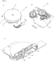
- FIG. 1 shows a single pipetting unit 1.
- the pipetting unit 1 comprises a Z-shaft 5 and a housing 10.
- the housing 10 which may also be designated as a cassette comprises the Z-shaft 5 by surrounding it and further surrounds Z-drive 15, Y-drive 35 and associated electronics (not shown) for controlling the Z-drive 15 in the housing's 10 flat design.
- the housing 10 comprises further, guidings for the Z- and Y-shaft (not shown in detail).
- a pipetting sub-unit 70 comprises a pipetting pump (not shown) which is arranged at a first end of the Z-shaft 5.
- the pipetting sub-unit 70 moves upwards and downwards whenever the Z-shaft 5 is actuated by the rotating Z-drive gear wheel 25 which engages into the toothed surface 16 of the Z-shaft 5.
- the housing 10 ( FIG. 2 ) can be made of different materials. It can be made of an injection moulded part with a stiffening plate, or alternatively it may be milled from a metal part or it can be made of zinc or aluminum via a die casting process.
- the Z-shaft 5 has a toothed surface 16 and the Z-drive 15 which comprises a flat Z-drive motor-gear unit 19 with a Z-drive gear wheel 25 engaging with its teeth into the toothed surface16 of the Z-shaft 5, which is shown in FIG. 3A .
- the flat Z-drive motor gear unit 19 can be in an embodiment an EC gear motor 17 ( FIG. 3B ) which is used to move the Z-shaft.
- the Z-drive contains a diametrically magnetized round magnet 21 at a first end of the motor shaft 22.
- the associated encoder chip 23 is located on a circuit board 24 on the opposite side of the motor axis and the magnet 21, as shown in FIG. 3C .
- This arrangement is used to determine the angle of rotation of the magnetic field and to determine an exact position of the Z-shaft.
- the Z-shaft of the pipetting unit is initialised via a slotted light barrier 60 which is arranged on the side of the housing facing the pipetting sub-unit 70 (comp. FIG. 1 ).
- a pin 61 (comp. FIG. 8 ) is arranged on the side of the pipetting sub-unit 70 facing the housing 10.
- FIG. 4 shows the Z-drive motor gear unit 19.
- the play between the toothed surface 16 of the Z-shaft 5 (not shown) and a Z-drive gear wheel 25 engaging in said toothed surface 16 is adjusted by means of a clamping screw 26 which can be moved in an oblong hole 28 for fixing a plate 27 to which the axis 25 of the Z-drive gear wheel is fixed. Once the adjustment has been made, plate 27 is fixed with clamping screw 26. Plate 27 rotates around axis 18 of a gear wheel of the Z-drive motor gear unit which actuates the Z-drive gear wheel 25.
- FIG. 5 shows an alternative to an adjustment by a movable plate.
- an inherently resilient Z-drive gear wheel 25 can be used for the Z-drive in order to realize a backlash-free installation.
- a gear wheel 25 may have a design with an elastic or compressible material arranged between outer gearing 30 and a centrally arranged hole 31.
- the shape of a material between outer gearing 30 an the centrally arranged hole 31 may allow a play between them, as FIG. 5B shows an S-shape in the sectional view on the right side of FIG. 5B. Different shapes like a Z-shape, a C-shape or other shapes may also be used.
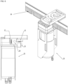
- FIG. 6 shows that a Y-drive 35 which may be provided by a compact DC gear motor (not shown) which is flexibly (elastically mounted in the X-direction) connected to the housing 10 (not shown).
- a Y-drive gear wheel 37 is mounted to the Y-drive motor shaft (not visible) for engaging into the toothed Y-drive gear rack 39.
- the Y-drive gear wheel 37 is guided by a deep-groove ball bearing 41 for the Y-drive.
- a magnetic tape encoder 43 is integrated into the housing (not shown) to determine the respective Y-position of the pipetting unit (not shown).
- a magnetic tape (not shown) is also attached to the toothed Y-drive gear rack 39.
- the pipetting unit is guided in the Y-direction by slide bearings 55 ( FIG. 10 ) on a cylindrical profile and by ball bearings 45 on a right-angled guiding bar 47 ( FIG. 8 ).
- the position of the cassette on a guiding bar can be adjusted vertically via the eccentrically mounted ball bearing 45, 48 ( FIG. 7, 8 ).
- the pressure spring in the spring loaded adjustment slide 51 of the second ball bearing automatically ensures a play-free movement between the ball bearing and the guiding bar.
- FIG. 9 and FIG. 10 show a Z-shaft guiding in more detail.
- the guiding enables a horizontal positioning and vertical movement of the Z-shaft (not shown).
- the Z-shaft is pushed by two L-bearings 50 with spring loaded counter bearings 52 towards a first longitudinal end of the housing 10.
- the friction must be high enough to hold the weight of the Z-shaft and at the same time small enough to keep the required force of the motor for actuating as low as possible.
- the drive can be damaged if the Z-shaft is moved manually.
- the Z-shaft can be cushioned with a spring 54 ( FIG. 9 ).
- the motor can be shortcircuited via a relay in the de-energised state, so that a braking effect is created by the motor when the rack is pushed up manually.
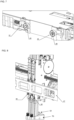
- FIG 10 shows Y-drive 35 and spring of counter bearing 52 for keeping the Z-shaft 5 in its position within the housing.
- FIG. 10 shows also slide bearings 55 which guide the pipetting unit in a Y-direction.
Landscapes
- Chemical & Material Sciences (AREA)
- Health & Medical Sciences (AREA)
- General Health & Medical Sciences (AREA)
- Life Sciences & Earth Sciences (AREA)
- Analytical Chemistry (AREA)
- Biochemistry (AREA)
- Physics & Mathematics (AREA)
- General Physics & Mathematics (AREA)
- Immunology (AREA)
- Pathology (AREA)
- Clinical Laboratory Science (AREA)
- Chemical Kinetics & Catalysis (AREA)
- Automatic Analysis And Handling Materials Therefor (AREA)
- Connection Of Motors, Electrical Generators, Mechanical Devices, And The Like (AREA)
Claims (15)
- Eine Pipettiereinheit (1), umfassend ein Gehäuse (10) mit zwei parallelen ebenen Flächen mit einem maximalen Abstand von 17.5 mm zwischen ihnen, wobei das Gehäuse (10) eine Z-Welle (5), die es umgibt, und eine Z-Wellenführung umfasst, wobei die Z-Wellenführung zwei L-Lager (50) mit federbelasteten Gegenlagern (52) umfasst, um die Z-Welle (5) mit einer ersten Außenfläche zu einem ersten Längsende des Gehäuses (10) zu schieben, wobei die Außenfläche der Z-Welle (5) gegenüber der ersten Außenfläche gezahnt ist; und wobei das Gehäuse (10) ferner eine Z-Antriebsmotor-Getriebeeinheit (19) mit einem Z-Antrieb (15) und einem Z-Antriebszahnrad (25) aufweist, das mit seinen Zähnen in die gezahnte Oberfläche der Z-Welle (16) eingreift, um die Z-Welle (5) aufwärts und abwärts zu bewegen; und wobei das Gehäuse (10) ferner einen Y-Antrieb (35) aufweist, der ein Y-Antriebszahnrad (37) umfasst, das an einer Y-Antriebsmotorwelle angebracht ist, wobei das Y-Antriebszahnrad (37) neben einer Öffnung in dem Gehäuse (10) angeordnet ist, um in eine gezahnte Y-Antriebszahnstange (39) einzugreifen.
- Die Pipettiereinheit (1) nach Anspruch 1, wobei der Z-Antrieb (15) ein Z-Antriebsmotor mit einer Z-Antriebsmotorwelle (22) ist, die einen diametral magnetisierten Rundmagneten (21) an einem ersten Ende der Z-Antriebsmotorwelle umfasst, und ein zugehöriger Encoderchip (23) auf einer Leiterplatte (24) auf der gegenüberliegenden Seite der Z-Antriebsmotorwelle (22) und des magnetisierten Rundmagneten (21) angeordnet ist, um den Drehwinkel eines Magnetfelds zu bestimmen, so dass die Position der Motorwelle (22) des Z-Antriebs bestimmt werden kann.
- Die Pipettiereinheit (1) nach Anspruch 1 oder 2, wobei das Gehäuse (10) eine geschlitzte Lichtschranke (60) zur Initialisierung der Z-Welle (5) aufweist.
- Die Pipettiereinheit (1) nach einem der Ansprüche 1 bis 3, wobei ein erstes Ende des Z-Welle (5) eine integrierte Pipettierpumpe zur Bereitstellung oder Aufnahme von Flüssigkeiten aufweist.
- Die Pipettiereinheit (1) nach einem der Ansprüche 1 bis 4, wobei der Y-Antrieb (35) ein Y-Antriebsmotor ist, der mit dem Gehäuse verbunden ist.
- Die Pipettiereinheit (1) nach einem der Ansprüche 1 bis 5, wobei eine Achse des Z-Antriebszahnrads (29) zum Eingriff in die Zahnfläche der Z-Welle (16) an einer Platte (27) angebracht ist, die durch eine Klemmschraube (26) in einem Langloch (28) gegen Verdrehen um die Achse des Z-Zahnrads (29) fixierbar ist, wobei die Klemmschraube (26) zur Einstellung der Position der Achse (29) im Langloch (28) bewegbar ist.
- Die Pipettiereinheit (1) nach einem der Ansprüche 1 bis 6, wobei das Z-Antriebszahnrad aus einem komprimierbaren Material besteht oder zwischen seinem Außenumfang und seiner Achse eine S-, Z- oder C-Form aufweist, die einen Spielausgleich ermöglicht.
- Die Pipettiereinheit (1) nach einem der Ansprüche 1 bis 7, wobei das Y-Antriebszahnrad (37) in einem Rillenkugellager (41) geführt ist.
- Die Pipettiereinheit (1) nach einem der Ansprüche 1 bis 8, mit einem Z-Antriebsmotor-Getriebe (19) zwischen dem Ende der Z-Antriebsmotorwelle des Z-Antriebs (15) und dem Z-Antriebszahnrad (25).
- Ein System zur Handhabung von Flüssigkeiten, umfassend eine Pipettiereinheit (1) nach einem der Ansprüche 1 bis 9.
- Das System nach Anspruch 10, mit einer Y-Antriebszahnstange (39), die durch die Öffnung im Gehäuse (10) geführt wird, in die das Y-Antriebszahnrad (37) des Y-Antriebs (35) eingreift.
- Das System nach einem der Ansprüche 10 oder 11, wobei das Gehäuse (10) der Pipettiereinheit (1) an einer Außenfläche mindestens zwei vertikal beabstandete Kugellager (41) zur Anordnung einer Führungsstange (47) zwischen ihnen aufweist.
- Das System nach Anspruch 12, wobei ein erstes der mindestens zwei vertikal beabstandeten Kugellager (41) mit einem Einstellschlitten verbunden ist, um das erste Kugellager vertikal zu bewegen, um den Abstand zwischen den mindestens zwei Kugellagern (41) einzustellen.
- Das System nach Anspruch 12 oder 13, bei dem mindestens eines der mindestens zwei Kugellager (41) auf einem Exzenter (48) zur vertikalen Einstellung der Position des Gehäuses (10) auf der Führungsstange (47) montiert ist.
- Das System nach einem der Ansprüche 10 bis 14, wobei in weiteren Öffnungen des Gehäuses (10) weitere Gleitlager (55) auf einem zylindrischen Profil angeordnet sind und an der Führungsstange (47) Kugellager (41) zur Führung von Bewegungen der Pipettiereinheit (1) in Y-Richtung angeordnet sind.
Applications Claiming Priority (1)
| Application Number | Priority Date | Filing Date | Title |
|---|---|---|---|
| LU102878A LU102878B1 (en) | 2021-11-15 | 2021-11-15 | Pipetting unit |
Publications (2)
| Publication Number | Publication Date |
|---|---|
| EP4180822A1 EP4180822A1 (de) | 2023-05-17 |
| EP4180822B1 true EP4180822B1 (de) | 2024-04-03 |
Family
ID=80122516
Family Applications (1)
| Application Number | Title | Priority Date | Filing Date |
|---|---|---|---|
| EP22202366.5A Active EP4180822B1 (de) | 2021-11-15 | 2022-10-19 | Pipettiereinheit |
Country Status (3)
| Country | Link |
|---|---|
| US (1) | US20230149917A1 (de) |
| EP (1) | EP4180822B1 (de) |
| LU (1) | LU102878B1 (de) |
Family Cites Families (20)
| Publication number | Priority date | Publication date | Assignee | Title |
|---|---|---|---|---|
| US4527437A (en) * | 1983-07-06 | 1985-07-09 | Wescor, Inc. | Pipette controller |
| US5306510A (en) * | 1988-01-14 | 1994-04-26 | Cyberlab, Inc. | Automated pipetting system |
| US7534395B2 (en) * | 2004-04-27 | 2009-05-19 | Beckman Coulter, Inc. | Hysteresis compensation system |
| IES20070831A2 (en) * | 2006-11-15 | 2009-03-04 | Trinity Res Ltd | A device for withdrawing a liquid sample from a container or for discharging a liquid sample into a container, and apparatus incorporating the device for withdrawing liquid samples from respective ones of a plurality of containers or for discharging liquid samples into respective ones of a plurality of containers |
| US8900527B2 (en) * | 2010-06-29 | 2014-12-02 | Roche Molecular Systems Inc. | Pipetting device with independently movable pipette units |
| US9044749B2 (en) * | 2012-02-29 | 2015-06-02 | Eppendorf Ag | Pipette |
| DE102012206239A1 (de) * | 2012-04-17 | 2013-10-17 | Hamilton Bonaduz Ag | Dosiervorrichtung, insbesondere Pipettierautomat mit Entsorgungsbehälter |
| US9295986B2 (en) * | 2012-05-02 | 2016-03-29 | Eppendorf Ag | Pipette with releasable locking of rotational position of actuating element |
| US20160266162A1 (en) * | 2013-11-06 | 2016-09-15 | Degree Of Freedom Scientific Machine Co., Ltd. | Fully-automatic pipetting instrument and use thereof |
| CN103846114B (zh) * | 2014-03-21 | 2016-08-31 | 北京自由度科学机器有限公司 | 全自动移液工作站和其用途 |
| WO2016081595A1 (en) * | 2014-11-18 | 2016-05-26 | Avidien Technologies | Multichannel air displacement pipettor |
| EP3096148B1 (de) * | 2015-05-20 | 2024-01-03 | Siemens Healthcare Diagnostics Products GmbH | Pipettiervorrichtung |
| DE102016118384B4 (de) * | 2016-09-28 | 2023-10-26 | Infineon Technologies Ag | Magnetische Winkelsensorvorrichtung und Betriebsverfahren |
| DE102016121817A1 (de) * | 2016-11-14 | 2018-05-17 | Ika-Werke Gmbh & Co. Kg | Handdosiervorrichtung und Handdosiervorrichtungsanordnung |
| US12392692B2 (en) * | 2017-03-09 | 2025-08-19 | Hologic, Inc. | Systems for automated preparation of biological specimens |
| EP3588099B1 (de) * | 2018-06-26 | 2024-09-25 | Tecan Trading Ag | Positionierungsanordnung für eine laborvorrichtung |
| US11420197B2 (en) * | 2018-11-05 | 2022-08-23 | Hycor Biomedical, Llc | Apparatus and method for mixing fluid or media by vibrating a pipette using nonconcentric masses |
| EP4162280A4 (de) * | 2020-06-04 | 2024-06-05 | Australian Laboratory Services Pty. Ltd. | Automatisierte flüssigkeitsausgabesysteme |
| EP3928868B1 (de) * | 2020-06-22 | 2024-11-27 | Eppendorf SE | Pipette für den gebrauch mit einer einen kolben und einen zylinder aufweisenden pipettenspitze oder spritze |
| CN111778137B (zh) * | 2020-06-29 | 2023-01-31 | 上海思路迪生物医学科技有限公司 | 一种三自由度文库制备卡盒及方法 |
-
2021
- 2021-11-15 LU LU102878A patent/LU102878B1/en active
-
2022
- 2022-10-19 EP EP22202366.5A patent/EP4180822B1/de active Active
- 2022-10-20 US US17/969,857 patent/US20230149917A1/en active Pending
Also Published As
| Publication number | Publication date |
|---|---|
| US20230149917A1 (en) | 2023-05-18 |
| EP4180822A1 (de) | 2023-05-17 |
| LU102878B1 (en) | 2023-05-15 |
Similar Documents
| Publication | Publication Date | Title |
|---|---|---|
| EP1767950B1 (de) | Verfahren und Vorrichtung zur präzisen Positionierung einer Pipettiervorrichtung | |
| US7998409B2 (en) | Specimen-transport module for multi-instrument clinical workcell | |
| CN111443214B (zh) | 一种电动移液设备 | |
| US10962991B2 (en) | Modular multi-channel syringe pump | |
| US9126162B2 (en) | Positioning unit for a functional unit | |
| EP3597728B1 (de) | Zellübertragungsvorrichtung und zellübertragungsverfahren | |
| CN213499061U (zh) | 一种调节平台 | |
| US20130280145A1 (en) | Liquid handler with dual pipetting groups | |
| EP4180822B1 (de) | Pipettiereinheit | |
| EP3647793B1 (de) | Ausgabeeinheit und automatisierter analysator | |
| EP1740923B1 (de) | Hystereseausgleichsystem | |
| CN107192842B (zh) | 兼具推送功能的伸缩定位型样本传送装置 | |
| US20110164316A1 (en) | Positioning system | |
| CN212083464U (zh) | 一种电动移液设备 | |
| EP1850136A1 (de) | Schüttlervorrichtung für ein Analysegerät und Analysegerät mit einer derartigen Vorrichtung | |
| EP3862756B1 (de) | Verstellbare halterung für automatische flüssigkeitshandhabungsanwendungen | |
| US20220244284A1 (en) | Device for moving probes | |
| EP4603175A1 (de) | Unwuchtkompensierter rüttler zum mischen von fluidproben | |
| CN222426048U (zh) | 准直器和x射线设备 | |
| JPH03293600A (ja) | 放射線照射装置 | |
| CN219417665U (zh) | 一种ic测试用下压装置 | |
| CN220910901U (zh) | 一种移液泵升降装置 | |
| CN221378001U (zh) | 一种用于多通道ivd检测仪器的发光盒移动装置 | |
| CN121244305A (zh) | 间距调整装置、移液组件及稀释液定量设备 | |
| CN217931704U (zh) | 一种全自动进样器阻挡装置 |
Legal Events
| Date | Code | Title | Description |
|---|---|---|---|
| PUAI | Public reference made under article 153(3) epc to a published international application that has entered the european phase |
Free format text: ORIGINAL CODE: 0009012 |
|
| STAA | Information on the status of an ep patent application or granted ep patent |
Free format text: STATUS: REQUEST FOR EXAMINATION WAS MADE |
|
| 17P | Request for examination filed |
Effective date: 20230413 |
|
| AK | Designated contracting states |
Kind code of ref document: A1 Designated state(s): AL AT BE BG CH CY CZ DE DK EE ES FI FR GB GR HR HU IE IS IT LI LT LU LV MC ME MK MT NL NO PL PT RO RS SE SI SK SM TR |
|
| P01 | Opt-out of the competence of the unified patent court (upc) registered |
Effective date: 20230710 |
|
| GRAP | Despatch of communication of intention to grant a patent |
Free format text: ORIGINAL CODE: EPIDOSNIGR1 |
|
| STAA | Information on the status of an ep patent application or granted ep patent |
Free format text: STATUS: GRANT OF PATENT IS INTENDED |
|
| GRAS | Grant fee paid |
Free format text: ORIGINAL CODE: EPIDOSNIGR3 |
|
| GRAA | (expected) grant |
Free format text: ORIGINAL CODE: 0009210 |
|
| STAA | Information on the status of an ep patent application or granted ep patent |
Free format text: STATUS: THE PATENT HAS BEEN GRANTED |
|
| INTG | Intention to grant announced |
Effective date: 20240216 |
|
| AK | Designated contracting states |
Kind code of ref document: B1 Designated state(s): AL AT BE BG CH CY CZ DE DK EE ES FI FR GB GR HR HU IE IS IT LI LT LU LV MC ME MK MT NL NO PL PT RO RS SE SI SK SM TR |
|
| REG | Reference to a national code |
Ref country code: CH Ref legal event code: EP |
|
| REG | Reference to a national code |
Ref country code: IE Ref legal event code: FG4D |
|
| REG | Reference to a national code |
Ref country code: DE Ref legal event code: R096 Ref document number: 602022002696 Country of ref document: DE |
|
| REG | Reference to a national code |
Ref country code: LT Ref legal event code: MG9D |
|
| REG | Reference to a national code |
Ref country code: NL Ref legal event code: MP Effective date: 20240403 |
|
| REG | Reference to a national code |
Ref country code: AT Ref legal event code: MK05 Ref document number: 1672900 Country of ref document: AT Kind code of ref document: T Effective date: 20240403 |
|
| PG25 | Lapsed in a contracting state [announced via postgrant information from national office to epo] |
Ref country code: NL Free format text: LAPSE BECAUSE OF FAILURE TO SUBMIT A TRANSLATION OF THE DESCRIPTION OR TO PAY THE FEE WITHIN THE PRESCRIBED TIME-LIMIT Effective date: 20240403 |
|
| PG25 | Lapsed in a contracting state [announced via postgrant information from national office to epo] |
Ref country code: NL Free format text: LAPSE BECAUSE OF FAILURE TO SUBMIT A TRANSLATION OF THE DESCRIPTION OR TO PAY THE FEE WITHIN THE PRESCRIBED TIME-LIMIT Effective date: 20240403 |
|
| PG25 | Lapsed in a contracting state [announced via postgrant information from national office to epo] |
Ref country code: IS Free format text: LAPSE BECAUSE OF FAILURE TO SUBMIT A TRANSLATION OF THE DESCRIPTION OR TO PAY THE FEE WITHIN THE PRESCRIBED TIME-LIMIT Effective date: 20240803 |
|
| PG25 | Lapsed in a contracting state [announced via postgrant information from national office to epo] |
Ref country code: BG Free format text: LAPSE BECAUSE OF FAILURE TO SUBMIT A TRANSLATION OF THE DESCRIPTION OR TO PAY THE FEE WITHIN THE PRESCRIBED TIME-LIMIT Effective date: 20240403 |
|
| PG25 | Lapsed in a contracting state [announced via postgrant information from national office to epo] |
Ref country code: HR Free format text: LAPSE BECAUSE OF FAILURE TO SUBMIT A TRANSLATION OF THE DESCRIPTION OR TO PAY THE FEE WITHIN THE PRESCRIBED TIME-LIMIT Effective date: 20240403 Ref country code: FI Free format text: LAPSE BECAUSE OF FAILURE TO SUBMIT A TRANSLATION OF THE DESCRIPTION OR TO PAY THE FEE WITHIN THE PRESCRIBED TIME-LIMIT Effective date: 20240403 |
|
| PG25 | Lapsed in a contracting state [announced via postgrant information from national office to epo] |
Ref country code: GR Free format text: LAPSE BECAUSE OF FAILURE TO SUBMIT A TRANSLATION OF THE DESCRIPTION OR TO PAY THE FEE WITHIN THE PRESCRIBED TIME-LIMIT Effective date: 20240704 |
|
| PG25 | Lapsed in a contracting state [announced via postgrant information from national office to epo] |
Ref country code: PT Free format text: LAPSE BECAUSE OF FAILURE TO SUBMIT A TRANSLATION OF THE DESCRIPTION OR TO PAY THE FEE WITHIN THE PRESCRIBED TIME-LIMIT Effective date: 20240805 |
|
| PG25 | Lapsed in a contracting state [announced via postgrant information from national office to epo] |
Ref country code: ES Free format text: LAPSE BECAUSE OF FAILURE TO SUBMIT A TRANSLATION OF THE DESCRIPTION OR TO PAY THE FEE WITHIN THE PRESCRIBED TIME-LIMIT Effective date: 20240403 |
|
| PG25 | Lapsed in a contracting state [announced via postgrant information from national office to epo] |
Ref country code: CZ Free format text: LAPSE BECAUSE OF FAILURE TO SUBMIT A TRANSLATION OF THE DESCRIPTION OR TO PAY THE FEE WITHIN THE PRESCRIBED TIME-LIMIT Effective date: 20240403 |
|
| PG25 | Lapsed in a contracting state [announced via postgrant information from national office to epo] |
Ref country code: AT Free format text: LAPSE BECAUSE OF FAILURE TO SUBMIT A TRANSLATION OF THE DESCRIPTION OR TO PAY THE FEE WITHIN THE PRESCRIBED TIME-LIMIT Effective date: 20240403 |
|
| PG25 | Lapsed in a contracting state [announced via postgrant information from national office to epo] |
Ref country code: PL Free format text: LAPSE BECAUSE OF FAILURE TO SUBMIT A TRANSLATION OF THE DESCRIPTION OR TO PAY THE FEE WITHIN THE PRESCRIBED TIME-LIMIT Effective date: 20240403 |
|
| PG25 | Lapsed in a contracting state [announced via postgrant information from national office to epo] |
Ref country code: LV Free format text: LAPSE BECAUSE OF FAILURE TO SUBMIT A TRANSLATION OF THE DESCRIPTION OR TO PAY THE FEE WITHIN THE PRESCRIBED TIME-LIMIT Effective date: 20240403 |
|
| PG25 | Lapsed in a contracting state [announced via postgrant information from national office to epo] |
Ref country code: PT Free format text: LAPSE BECAUSE OF FAILURE TO SUBMIT A TRANSLATION OF THE DESCRIPTION OR TO PAY THE FEE WITHIN THE PRESCRIBED TIME-LIMIT Effective date: 20240805 Ref country code: PL Free format text: LAPSE BECAUSE OF FAILURE TO SUBMIT A TRANSLATION OF THE DESCRIPTION OR TO PAY THE FEE WITHIN THE PRESCRIBED TIME-LIMIT Effective date: 20240403 Ref country code: NO Free format text: LAPSE BECAUSE OF FAILURE TO SUBMIT A TRANSLATION OF THE DESCRIPTION OR TO PAY THE FEE WITHIN THE PRESCRIBED TIME-LIMIT Effective date: 20240703 Ref country code: LV Free format text: LAPSE BECAUSE OF FAILURE TO SUBMIT A TRANSLATION OF THE DESCRIPTION OR TO PAY THE FEE WITHIN THE PRESCRIBED TIME-LIMIT Effective date: 20240403 Ref country code: IS Free format text: LAPSE BECAUSE OF FAILURE TO SUBMIT A TRANSLATION OF THE DESCRIPTION OR TO PAY THE FEE WITHIN THE PRESCRIBED TIME-LIMIT Effective date: 20240803 Ref country code: HR Free format text: LAPSE BECAUSE OF FAILURE TO SUBMIT A TRANSLATION OF THE DESCRIPTION OR TO PAY THE FEE WITHIN THE PRESCRIBED TIME-LIMIT Effective date: 20240403 Ref country code: GR Free format text: LAPSE BECAUSE OF FAILURE TO SUBMIT A TRANSLATION OF THE DESCRIPTION OR TO PAY THE FEE WITHIN THE PRESCRIBED TIME-LIMIT Effective date: 20240704 Ref country code: FI Free format text: LAPSE BECAUSE OF FAILURE TO SUBMIT A TRANSLATION OF THE DESCRIPTION OR TO PAY THE FEE WITHIN THE PRESCRIBED TIME-LIMIT Effective date: 20240403 Ref country code: ES Free format text: LAPSE BECAUSE OF FAILURE TO SUBMIT A TRANSLATION OF THE DESCRIPTION OR TO PAY THE FEE WITHIN THE PRESCRIBED TIME-LIMIT Effective date: 20240403 Ref country code: CZ Free format text: LAPSE BECAUSE OF FAILURE TO SUBMIT A TRANSLATION OF THE DESCRIPTION OR TO PAY THE FEE WITHIN THE PRESCRIBED TIME-LIMIT Effective date: 20240403 Ref country code: BG Free format text: LAPSE BECAUSE OF FAILURE TO SUBMIT A TRANSLATION OF THE DESCRIPTION OR TO PAY THE FEE WITHIN THE PRESCRIBED TIME-LIMIT Effective date: 20240403 Ref country code: AT Free format text: LAPSE BECAUSE OF FAILURE TO SUBMIT A TRANSLATION OF THE DESCRIPTION OR TO PAY THE FEE WITHIN THE PRESCRIBED TIME-LIMIT Effective date: 20240403 Ref country code: RS Free format text: LAPSE BECAUSE OF FAILURE TO SUBMIT A TRANSLATION OF THE DESCRIPTION OR TO PAY THE FEE WITHIN THE PRESCRIBED TIME-LIMIT Effective date: 20240703 |
|
| REG | Reference to a national code |
Ref country code: DE Ref legal event code: R097 Ref document number: 602022002696 Country of ref document: DE |
|
| PG25 | Lapsed in a contracting state [announced via postgrant information from national office to epo] |
Ref country code: DK Free format text: LAPSE BECAUSE OF FAILURE TO SUBMIT A TRANSLATION OF THE DESCRIPTION OR TO PAY THE FEE WITHIN THE PRESCRIBED TIME-LIMIT Effective date: 20240403 |
|
| PG25 | Lapsed in a contracting state [announced via postgrant information from national office to epo] |
Ref country code: EE Free format text: LAPSE BECAUSE OF FAILURE TO SUBMIT A TRANSLATION OF THE DESCRIPTION OR TO PAY THE FEE WITHIN THE PRESCRIBED TIME-LIMIT Effective date: 20240403 |
|
| PG25 | Lapsed in a contracting state [announced via postgrant information from national office to epo] |
Ref country code: SK Free format text: LAPSE BECAUSE OF FAILURE TO SUBMIT A TRANSLATION OF THE DESCRIPTION OR TO PAY THE FEE WITHIN THE PRESCRIBED TIME-LIMIT Effective date: 20240403 Ref country code: RO Free format text: LAPSE BECAUSE OF FAILURE TO SUBMIT A TRANSLATION OF THE DESCRIPTION OR TO PAY THE FEE WITHIN THE PRESCRIBED TIME-LIMIT Effective date: 20240403 |
|
| PG25 | Lapsed in a contracting state [announced via postgrant information from national office to epo] |
Ref country code: SM Free format text: LAPSE BECAUSE OF FAILURE TO SUBMIT A TRANSLATION OF THE DESCRIPTION OR TO PAY THE FEE WITHIN THE PRESCRIBED TIME-LIMIT Effective date: 20240403 |
|
| PG25 | Lapsed in a contracting state [announced via postgrant information from national office to epo] |
Ref country code: SM Free format text: LAPSE BECAUSE OF FAILURE TO SUBMIT A TRANSLATION OF THE DESCRIPTION OR TO PAY THE FEE WITHIN THE PRESCRIBED TIME-LIMIT Effective date: 20240403 Ref country code: SK Free format text: LAPSE BECAUSE OF FAILURE TO SUBMIT A TRANSLATION OF THE DESCRIPTION OR TO PAY THE FEE WITHIN THE PRESCRIBED TIME-LIMIT Effective date: 20240403 Ref country code: RO Free format text: LAPSE BECAUSE OF FAILURE TO SUBMIT A TRANSLATION OF THE DESCRIPTION OR TO PAY THE FEE WITHIN THE PRESCRIBED TIME-LIMIT Effective date: 20240403 Ref country code: EE Free format text: LAPSE BECAUSE OF FAILURE TO SUBMIT A TRANSLATION OF THE DESCRIPTION OR TO PAY THE FEE WITHIN THE PRESCRIBED TIME-LIMIT Effective date: 20240403 Ref country code: DK Free format text: LAPSE BECAUSE OF FAILURE TO SUBMIT A TRANSLATION OF THE DESCRIPTION OR TO PAY THE FEE WITHIN THE PRESCRIBED TIME-LIMIT Effective date: 20240403 |
|
| PLBE | No opposition filed within time limit |
Free format text: ORIGINAL CODE: 0009261 |
|
| STAA | Information on the status of an ep patent application or granted ep patent |
Free format text: STATUS: NO OPPOSITION FILED WITHIN TIME LIMIT |
|
| 26N | No opposition filed |
Effective date: 20250106 |
|
| PG25 | Lapsed in a contracting state [announced via postgrant information from national office to epo] |
Ref country code: SI Free format text: LAPSE BECAUSE OF FAILURE TO SUBMIT A TRANSLATION OF THE DESCRIPTION OR TO PAY THE FEE WITHIN THE PRESCRIBED TIME-LIMIT Effective date: 20240403 |
|
| PG25 | Lapsed in a contracting state [announced via postgrant information from national office to epo] |
Ref country code: MC Free format text: LAPSE BECAUSE OF FAILURE TO SUBMIT A TRANSLATION OF THE DESCRIPTION OR TO PAY THE FEE WITHIN THE PRESCRIBED TIME-LIMIT Effective date: 20240403 |
|
| PG25 | Lapsed in a contracting state [announced via postgrant information from national office to epo] |
Ref country code: LU Free format text: LAPSE BECAUSE OF NON-PAYMENT OF DUE FEES Effective date: 20241019 Ref country code: BE Free format text: LAPSE BECAUSE OF NON-PAYMENT OF DUE FEES Effective date: 20241031 |
|
| REG | Reference to a national code |
Ref country code: BE Ref legal event code: MM Effective date: 20241031 |
|
| PG25 | Lapsed in a contracting state [announced via postgrant information from national office to epo] |
Ref country code: SE Free format text: LAPSE BECAUSE OF FAILURE TO SUBMIT A TRANSLATION OF THE DESCRIPTION OR TO PAY THE FEE WITHIN THE PRESCRIBED TIME-LIMIT Effective date: 20240403 |
|
| PG25 | Lapsed in a contracting state [announced via postgrant information from national office to epo] |
Ref country code: IE Free format text: LAPSE BECAUSE OF NON-PAYMENT OF DUE FEES Effective date: 20241019 |
|
| REG | Reference to a national code |
Ref country code: CH Ref legal event code: U11 Free format text: ST27 STATUS EVENT CODE: U-0-0-U10-U11 (AS PROVIDED BY THE NATIONAL OFFICE) Effective date: 20251101 |
|
| PGFP | Annual fee paid to national office [announced via postgrant information from national office to epo] |
Ref country code: DE Payment date: 20251020 Year of fee payment: 4 |
|
| PGFP | Annual fee paid to national office [announced via postgrant information from national office to epo] |
Ref country code: IT Payment date: 20251031 Year of fee payment: 4 |
|
| PG25 | Lapsed in a contracting state [announced via postgrant information from national office to epo] |
Ref country code: IT Free format text: LAPSE BECAUSE OF NON-PAYMENT OF DUE FEES Effective date: 20241019 |
|
| PGFP | Annual fee paid to national office [announced via postgrant information from national office to epo] |
Ref country code: FR Payment date: 20251024 Year of fee payment: 4 |
|
| PGFP | Annual fee paid to national office [announced via postgrant information from national office to epo] |
Ref country code: CH Payment date: 20251101 Year of fee payment: 4 |
|
| PG25 | Lapsed in a contracting state [announced via postgrant information from national office to epo] |
Ref country code: CY Free format text: LAPSE BECAUSE OF FAILURE TO SUBMIT A TRANSLATION OF THE DESCRIPTION OR TO PAY THE FEE WITHIN THE PRESCRIBED TIME-LIMIT; INVALID AB INITIO Effective date: 20221019 |
|
| PG25 | Lapsed in a contracting state [announced via postgrant information from national office to epo] |
Ref country code: HU Free format text: LAPSE BECAUSE OF FAILURE TO SUBMIT A TRANSLATION OF THE DESCRIPTION OR TO PAY THE FEE WITHIN THE PRESCRIBED TIME-LIMIT; INVALID AB INITIO Effective date: 20221019 |