EP4180752B1 - Klemme für ein kühl-/gefriergerät und kühl-/gefriergerät damit - Google Patents
Klemme für ein kühl-/gefriergerät und kühl-/gefriergerät damit Download PDFInfo
- Publication number
- EP4180752B1 EP4180752B1 EP21796490.7A EP21796490A EP4180752B1 EP 4180752 B1 EP4180752 B1 EP 4180752B1 EP 21796490 A EP21796490 A EP 21796490A EP 4180752 B1 EP4180752 B1 EP 4180752B1
- Authority
- EP
- European Patent Office
- Prior art keywords
- clamping
- cover
- limiting protrusion
- clip
- clamping member
- Prior art date
- Legal status (The legal status is an assumption and is not a legal conclusion. Google has not performed a legal analysis and makes no representation as to the accuracy of the status listed.)
- Active
Links
Images




Classifications
-
- F—MECHANICAL ENGINEERING; LIGHTING; HEATING; WEAPONS; BLASTING
- F25—REFRIGERATION OR COOLING; COMBINED HEATING AND REFRIGERATION SYSTEMS; HEAT PUMP SYSTEMS; MANUFACTURE OR STORAGE OF ICE; LIQUEFACTION SOLIDIFICATION OF GASES
- F25D—REFRIGERATORS; COLD ROOMS; ICE-BOXES; COOLING OR FREEZING APPARATUS NOT OTHERWISE PROVIDED FOR
- F25D29/00—Arrangement or mounting of control or safety devices
- F25D29/005—Mounting of control devices
-
- F—MECHANICAL ENGINEERING; LIGHTING; HEATING; WEAPONS; BLASTING
- F25—REFRIGERATION OR COOLING; COMBINED HEATING AND REFRIGERATION SYSTEMS; HEAT PUMP SYSTEMS; MANUFACTURE OR STORAGE OF ICE; LIQUEFACTION SOLIDIFICATION OF GASES
- F25D—REFRIGERATORS; COLD ROOMS; ICE-BOXES; COOLING OR FREEZING APPARATUS NOT OTHERWISE PROVIDED FOR
- F25D23/00—General constructional features
- F25D23/02—Doors; Covers
- F25D23/04—Doors; Covers with special compartments, e.g. butter conditioners
-
- G—PHYSICS
- G06—COMPUTING OR CALCULATING; COUNTING
- G06K—GRAPHICAL DATA READING; PRESENTATION OF DATA; RECORD CARRIERS; HANDLING RECORD CARRIERS
- G06K19/00—Record carriers for use with machines and with at least a part designed to carry digital markings
- G06K19/06—Record carriers for use with machines and with at least a part designed to carry digital markings characterised by the kind of the digital marking, e.g. shape, nature, code
- G06K19/067—Record carriers with conductive marks, printed circuits or semiconductor circuit elements, e.g. credit or identity cards also with resonating or responding marks without active components
- G06K19/07—Record carriers with conductive marks, printed circuits or semiconductor circuit elements, e.g. credit or identity cards also with resonating or responding marks without active components with integrated circuit chips
- G06K19/0723—Record carriers with conductive marks, printed circuits or semiconductor circuit elements, e.g. credit or identity cards also with resonating or responding marks without active components with integrated circuit chips the record carrier comprising an arrangement for non-contact communication, e.g. wireless communication circuits on transponder cards, non-contact smart cards or RFIDs
-
- G—PHYSICS
- G06—COMPUTING OR CALCULATING; COUNTING
- G06K—GRAPHICAL DATA READING; PRESENTATION OF DATA; RECORD CARRIERS; HANDLING RECORD CARRIERS
- G06K19/00—Record carriers for use with machines and with at least a part designed to carry digital markings
- G06K19/06—Record carriers for use with machines and with at least a part designed to carry digital markings characterised by the kind of the digital marking, e.g. shape, nature, code
- G06K19/067—Record carriers with conductive marks, printed circuits or semiconductor circuit elements, e.g. credit or identity cards also with resonating or responding marks without active components
- G06K19/07—Record carriers with conductive marks, printed circuits or semiconductor circuit elements, e.g. credit or identity cards also with resonating or responding marks without active components with integrated circuit chips
- G06K19/077—Constructional details, e.g. mounting of circuits in the carrier
- G06K19/07749—Constructional details, e.g. mounting of circuits in the carrier the record carrier being capable of non-contact communication, e.g. constructional details of the antenna of a non-contact smart card
- G06K19/07758—Constructional details, e.g. mounting of circuits in the carrier the record carrier being capable of non-contact communication, e.g. constructional details of the antenna of a non-contact smart card arrangements for adhering the record carrier to further objects or living beings, functioning as an identification tag
-
- F—MECHANICAL ENGINEERING; LIGHTING; HEATING; WEAPONS; BLASTING
- F25—REFRIGERATION OR COOLING; COMBINED HEATING AND REFRIGERATION SYSTEMS; HEAT PUMP SYSTEMS; MANUFACTURE OR STORAGE OF ICE; LIQUEFACTION SOLIDIFICATION OF GASES
- F25D—REFRIGERATORS; COLD ROOMS; ICE-BOXES; COOLING OR FREEZING APPARATUS NOT OTHERWISE PROVIDED FOR
- F25D2500/00—Problems to be solved
- F25D2500/06—Stock management
Definitions
- the present invention relates to the field of refrigerating and freezing storage technologies, and particularly to a clip and a refrigerating/freezing apparatus with same.
- JP 5005157694 A discloses how to provide an IC tag and a tag detection system that enables not only easy detachment and also replacement of the IC tag, with respect to a target article that comes in various shapes, but also in various storage states and arrangement states, and enable automatic management even of position, when such mounted targets are arrayed.
- the tag detection system comprises the IC tags and a tag detection device capable of contactless intercommunication.
- CN 204635878 U discloses a utility model comprising a clip with electronic tags, including punch holder and the lower plate that relative up -down set up, the punch holder be in the same place through the shaft is articulated with the lower plate, and the lower plate is including the plate body and the lower cover of setting from top to bottom, and the lower cover is equipped with the cavity of top end opening, and plate body bottom outer fringe is equipped with a plurality of fixture blocks that stretch out downwards, and the cavity side wall of lower cover is equipped with a plurality of draw -in grooves with a plurality of fixture block looks blocks, is equipped with in the cavity of lower cover and upwards stretches out two gear boards, is provided with electronic label module between the two gear boards, and electronic label module includes electronic tags and cladding in the
- a columnar body includes a metal body with an insulating film.
- a loop-shaped antenna conductor is provided on an upper surface of the columnar body via an insulating pedestal.
- the loop surface of the antenna conductor is parallel or substantially parallel to the upper surface of the columnar body.
- two terminal electrodes are provided on the lower surface of a RFIC element.
- the RFIC element is mounted on the antenna conductor such that the two terminal electrodes are connected to both ends of the antenna conductor, respectively.
- JP 5029174 B discloses how to provide a non-contact type data carrier device which is easily attached to an object.
- the non-contact type data carrier device is provided with: a metal eyeball clip having a through-hole, a non-contact type data carrier having at least an antenna and an IC chip electrically connected to the antenna, a resin PP holder in which the non-contact type data carrier having been installed; a mounting means for mounting the PP holder on the eyeball clip by using the hole of the eyeball clip.
- the mounting means is provided with: a resin screw to be inserted into the hole of the eyeball clip and a hole of the PP holder; a resin nut to be fit into the screw; and a resin washer arranged between the screw and the nut.
- CN 205708041 U discloses the utility model provides an electronic tags press from both sides and refrigerator, wherein, electronic tags press from both sides and include: the base is provided with first buckle in the first side of base, the second side at the base is installed to the clip to form the installation cavity with the second side of base, electronic label module installs in the installation cavity, wherein, and the last food information that is provided with of electronic label module.
- first buckle is the pothook
- this technical scheme electronic tags press from both sides including clip, base and install the electronic tags module between clip and base
- the base still is provided with first buckle for example the pothook on keeping away from one side of electronic tags module
- this first buckle can with inside wall such as refrigerator on correspond the second buckle that sets up for example block the hole and cooperate to alright press from both sides this electronic tags and install on the inside wall of objects such as refrigerator.
- this kind of electronic tags clamp is because the fixed knot who press from both sides electronic tags constructs the setting on the lateral wall of electronic tags clamp to be convenient for very much press from both sides to get to this electronic tags put.
- An object of the present invention is to provide a clip and a refrigerating/freezing apparatus with same, which solve at least the above problem.
- a further object of the present invention is to provide a clip which can be used as an electronic tag to realize intelligent management of food in a refrigerating/freezing apparatus.
- the present invention provides a clip according to claim 1, including:
- the first clamping part includes a first cover and a first clamping member, and the first clamping member is arranged on a side of the first cover close to the second clamping part;
- a positioning post is formed on the first cover and/or the second cover; and the positioning post is sleeved with the spring.
- a first limiting protrusion is formed on an inner surface of the first cover, and the rotary shafts are formed on a left side and a right side of the first limiting protrusion respectively;
- a second limiting protrusion is formed on an inner surface of the second cover, a notch is formed in a position of the second limiting protrusion corresponding to the first limiting protrusion, and the rotary shaft holes are formed in positions of a left side and a right side of the second limiting protrusion corresponding to the rotary shafts respectively, such that the first limiting protrusion is fitted at the notch, and the rotary shafts are fitted in the rotary shaft holes.
- the first clamping member is configured to have an upper end fixed to the first limiting protrusion and a lower end fixed to the first cover; and the second clamping member is configured to have an upper end fixed to the second limiting protrusion and a lower end fixed to the second cover.
- the first clamping member is configured to have the upper end fixedly clamped to the first limiting protrusion and the lower end fixedly clamped to the first cover; and the second clamping member is configured to have the upper end abutting against the second limiting protrusion and the lower end fixedly clamped to the second cover.
- the first cover has a first body part and a bottom wall part extending from a bottom end of the first body part towards the second cover, the first limiting protrusion is formed at an upper middle part of an inner surface of the first body part, a first gap is formed between a lower part of the first limiting protrusion and the inner surface of the first body part, and a first clamping opening is formed on an inner side surface of the bottom wall part of the first cover;
- the first clamping member has a second body part as well as a top wall part and a bottom wall part which are formed by extending from a top end and a bottom end of the second body part towards the first cover respectively, a first clamping hook protruding upwards is formed on the top wall part of the first clamping member, a second clamping hook is formed on an outer side surface of the bottom wall part of the first clamping member, the first clamping hook is fixed to the first limiting protrusion through the first gap, and the second clamping hook is fitted in the first clamping opening.
- the second cover has a third body part and a bottom wall part extending from a bottom end of the third body part towards the first cover, the second limiting protrusion is formed at an upper middle part of an inner surface of the third body part, a second gap is formed between a lower part of the second limiting protrusion and the inner surface of the third body part, and a second clamping opening is formed on an inner side surface of the bottom wall part of the second cover;
- the second clamping member has a fourth body part and a bottom wall part formed by extending from a bottom end of the fourth body part towards the second cover, a top end of the fourth body part abuts against a lower surface of the second limiting protrusion through the second gap, a third clamping hook is formed on an outer side surface of the bottom wall part of the second clamping member, and the third clamping hook is fitted in the second clamping opening.
- the present application further provides a refrigerating/freezing apparatus, including:
- the clip an ingenious structure and is easy to configure and use, and is particularly suitable for being used in a refrigerating/freezing apparatus, such as a high-end refrigerator, to dynamically monitor food, thereby realizing intelligent food management, and improving the intelligence of the refrigerating/freezing apparatus.
- a refrigerating/freezing apparatus such as a high-end refrigerator
- the clip has an ingenious overall design and a compact structure.
- the stable assembly of components is guaranteed, and the clip is not prone to deformation and has a long service life.
- Embodiments of the present invention provide a clip 200 according to claim 1 and a refrigerating/freezing apparatus with it, and the refrigerating/freezing apparatus can be an apparatus with refrigerating and freezing functions, such as a refrigerator, a freezer, or the like.
- the clip 200 according to claim 1 and the refrigerating/freezing apparatus according to the embodiments will be described in detail below with reference to Figs. 1 to 6 .
- Figs. 1 to 6 Herein, for convenience of description, “front”, “rear”, “left”, “right”, “upper” and “lower” in the structural description of the clip 200 are explained with reference to the directions in Fig. 1 , and it may be understood that the clip 200 may be vertically placed as shown in Fig. 1 , or obliquely or horizontally placed during application.
- Fig. 1 is a schematic perspective structural diagram of a clip 200 according to an embodiment of the present invention.
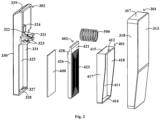
- Fig. 2 is a schematic exploded diagram of the clip 200 shown in Fig. 1 .
- Fig. 3 is a schematic sectional diagram of the clip 200 shown in Fig. 1 .
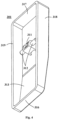
- Fig. 4 is a schematic perspective structural diagram of a first cover 301 of the clip 200 shown in Fig. 1 .
- the clip 200 includes: a first clamping part 201, a second clamping part 202, a spring 500 and a chip 600.
- a rotary shaft 312 is arranged on the first clamping part 201.
- the second clamping part 202 is arranged opposite to the first clamping part 201, a rotary shaft hole 323 is arranged on the second clamping part 202 corresponding to the rotary shaft 312, and the rotary shaft 312 is fitted in the rotary shaft hole 323 to achieve a rotational connection of the first clamping part 201 and the second clamping part 202.
- the spring 500 is sandwiched between the first clamping part 201 and the second clamping part 202.
- the chip 600 is arranged in the first clamping part 201 and/or the second clamping part 202 and used for storing data information.
- the first clamping part 201 and the second clamping part 202 are rotationally connected by the interference fit of the rotary shaft 312 and the rotary shaft hole 323, and controllably rotate by compression deformation of the spring 500.
- the spring 500 when the clip 200 is in an idle state, that is, not used, the spring 500 is in an initial state and does not elastically deform, and at this point, inner side surfaces of sides of the first clamping part 201 and the second clamping part 202 apart from the spring 500 are attached; when the spring 500 is stressed to be compressed, ends of the sides of the first clamping part 201 and the second clamping part 202 apart from the spring 500 get away from each other to form a gap between the first clamping part 201 and the second clamping part 202, which is convenient for a user to place an article in the gap between the first clamping part 201 and the second clamping part 202; after the article is placed in the gap, a force is no longer applied to the spring 500, the spring 500 is partially restored from the deformation, and the ends of the sides of the first clamping part 201 and the second clamping part 202 apart from the spring 500 get close to each other to form a clamping force between the clip 200 and the article; when the clip 200 is required to be removed, a force
- the clip 200 is set to include the first clamping part 201, the second clamping part 202, the spring 500 and the chip 600, and the chip 600 is used for storing the data information, such as food information, such that the clip 200 can be used as an electronic tag; meanwhile, the rotary shaft 312 is arranged on the first clamping part 201, the rotary shaft hole 323 is arranged on the second clamping part 202, which is arranged opposite to the first clamping part 201, corresponding to the rotary shaft 312, and the rotary shaft 312 is fitted in the rotary shaft hole 323 to realize the rotational connection of the first clamping part 201 and the second clamping part 202; the spring 500 is sandwiched between the first clamping part 201 and the second clamping part 202, such that the clip 200 has an ingenious structure and easy to configure and use, and is particularly suitable for being used in a refrigerating/freezing apparatus, such as a high-end refrigerator, to dynamically monitor food, thereby realizing intelligent food
- the first clamping part 201 and the second clamping part 202 may be an integral structure or a split structure.
- the first clamping part 201 includes a first cover 301 and a first clamping member 401, and the first clamping member 401 is arranged on a side of the first cover 301 close to the second clamping part 202;
- the second clamping part 202 includes a second cover 302 and a second clamping member 402, and the second clamping member 402 is arranged on a side of the second cover 302 close to the first clamping part 201;
- the spring 500 is sandwiched between the first cover 301 and the second cover 302; outer surfaces of the first clamping members 401 and the second clamping member 402 are oppositely arranged to define a clamping region 700 of the clip 200.
- the first clamping part 201 of the clip 200 includes the first cover 301 and the first clamping member 401
- the second clamping part 202 includes the second cover 302 and the second clamping member 402
- the spring 500 is sandwiched between the first cover 301 and the second cover 302
- the outer surfaces of the first clamping member 401 and the second clamping member 402 are oppositely arranged to define the clamping region 700 of the clip 200, such that the clip has an ingenious overall design and a compact structure, and the chip 600 is easy to place and replace.
- the chip 600 is arranged within the first clamping part 201, that is, located between the first cover 301 and the first clamping member 401, or may be arranged within the second clamping part 202, that is, located between the second cover 302 and the second clamping member 402.
- the first cover 301 is apart from the inner side of the door body 101
- the second cover 302 is close to the inner side of the door body 101
- the chip 600 is arranged in the second clamping part 202 and close to the second cover 302, as shown in Fig. 3 , so as to facilitate the arrangement of an antenna board 103 and wiring.
- a positioning post 324 is arranged on the first cover 301 and/or the second cover 302; and the positioning post 324 is sleeved with the spring 500.
- the positioning post 324 is formed on the second cover 302.
- a first limiting protrusion 311 is formed on an inner surface of the first cover 301, and the rotary shafts 312 are formed on a left side and a right side of the first limiting protrusion 311 respectively;
- a second limiting protrusion 321 is formed on an inner surface of the second cover 302, a notch 322 is formed in a position of the second limiting protrusion 321 corresponding to the first limiting protrusion 311, and the rotary shaft holes 323 are formed in positions of a left side and a right side of the second limiting protrusion 321 corresponding to the rotary shafts 312 respectively, such that the first limiting protrusion 311 is fitted at the notch 322, and the rotary shafts 312 are fitted in the rotary shaft holes 323.
- the notch 322 is arranged on the second limiting protrusion 321, the first limiting protrusion 311 is fitted in the notch 322, and meanwhile, the rotary shafts 312 on the two sides are fitted in the rotary shaft holes 323 on the two sides respectively, such that a rotary structure of the first cover 301 and the second cover 302 is quite reliable, and the use stability of the clip 200 is high.
- the first clamping member 401 may be configured to have an upper end fixed to the first limiting protrusion 311 and a lower end fixed to the first cover 301; the second clamping member 402 may be configured to have an upper end fixed to the second limiting protrusion 321 and a lower end fixed to the second cover 302.
- the first clamping member 401 may be configured to have the upper end fixedly clamped to the first limiting protrusion 311 and the lower end fixedly clamped to the first cover 301;
- the second clamping member 402 may be configured to have the upper end abutting against the second limiting protrusion 321 and the lower end fixedly clamped to the second cover 302.
- the first clamping member 401 of the clip 200 is configured to have the upper end fixed to the first limiting protrusion 311 and the lower end fixed to the first cover 301; the second clamping member 402 is configured to have the upper end fixed to the second limiting protrusion 321, and the lower end fixed to the second cover 302, such that stable assembly of components is guaranteed, and the clip is not prone to deformation and has a long service life.
- the first cover 301 has a first body part 313 and a bottom wall part 316 extending from a bottom end of the first body part 313 towards the second cover 302, the first limiting protrusion 311 is formed at an upper middle part of an inner surface of the first body part 313, a first gap 314 is formed between a lower part of the first limiting protrusion 311 and the inner surface of the first body part 313, and a first clamping opening (not shown in the figures) is formed on an inner side surface of the bottom wall part 316 of the first cover 301.
- the first clamping member 401 has a second body part 411 as well as a top wall part 415 and a bottom wall part 416 which are formed by extending from a top end and a bottom end of the second body part 411 towards the first cover 301 respectively, a first clamping hook 412 protruding upwards is formed on the top wall part 415 of the first clamping member 401, a second clamping hook (not shown in the figures) is formed on an outer side surface of the bottom wall part 416 of the first clamping member 401, the first clamping hook 412 is fixed to the first limiting protrusion 311 through the first gap 314, and the second clamping hook is fitted in the first clamping opening.
- the first cover 301 and the first clamping member 401 of the clip 200 achieve close fit by means of the first gap 314, the first clamping hook 412, the first clamping opening and the second clamping hook, and meanwhile, since the first clamping member 401 actually provides the clamping region 700, the outer shape of the first cover 301 may be specially designed, so as to make the appearance of the entire clip 200 better.
- the second cover 302 has a third body part 325 and a bottom wall part 328 extending from a bottom end of the third body part 325 towards the first cover 301, the second limiting protrusion 321 is formed at an upper middle part of an inner surface of the third body part 325, a second gap 326 is formed between a lower part of the second limiting protrusion 321 and the inner surface of the third body part 325, and a second clamping opening 327 is formed on an inner side surface of the bottom wall part 328 of the second cover 302.
- the second clamping member 402 has a fourth body part 421 and a bottom wall part 424 formed by extending from a bottom end of the fourth body part 421 towards the second cover 302, a top end of the fourth body part 421 abuts against a lower surface of the second limiting protrusion 321 through the second gap 326, a third clamping hook (not shown in the figures) is formed on an outer side surface of the bottom wall part 424 of the second clamping member 402, and the third clamping hook is fitted in the second clamping opening 327.
- the second cover 302 and the second clamping member 402 of the clip 200 realize close fit by the abutment of the fourth body part 421 via the second gap 326, the second clamping opening 327 and the third clamping hook.
- the chip 600 is preferably arranged between the second cover 302 and the second clamping member 402, and the insertion and removal of the chip 600 can be facilitated by a fixing structure in which abutment is performed on one side and clamping is performed on the other side. As shown in Figs.
- an arc-shaped limiting protrusion 428 is preferably formed on a side of the fourth body part 421 facing the third body part 325 in an extension mode, so as to facilitate assembly of the second clamping member 402.
- an anti-slip protrusion 414 is further arranged on the outer surface of the first clamping member 401, and an anti-slip protrusion 423 is further arranged on the outer surface of the second clamping member 402, so as to further enhance the clamping performance of the clip 200.
- the first body part 313 of the first cover 301 forms a folded structure having a vertical section and an inclined section, and a top wall part 317, a left side wall part 318, a right side wall part 319, and the bottom wall part 316 are formed around the first body part 313.
- the second body part 411 of the first clamping member 401 has a planar structure, and the top wall part 415, a left side wall part 417, a right side wall part 418, and the bottom wall part 416 are also formed around the second body part 411.
- the second body part 411 is spaced apart from the first body part 313, the top wall part 415 of the first clamping member 401 abuts against a lower surface of the first limiting protrusion 311, the left side wall part 417 abuts against an inner surface of the left side wall part 318 of the first cover 301, the right side wall part 418 abuts against an inner surface of the right side wall part 319 of the first cover 301, and the bottom wall part 416 abuts against an inner surface of the bottom wall part 316 of the first cover 301, such that the first clamping member 401 is completely wrapped in the first cover 301.
- the third body part 325 of the second cover 302 has a planar structure, and a top wall part 329, a left side wall part 330, a right side wall part 331, and the bottom wall part 328 are formed around the third body part 325.
- the fourth body part 421 of the second clamping member 402 has a planar structure, and a left side wall part 426, a right side wall part 427, and the bottom wall part 424 are formed on three sides of the fourth body part 421 respectively.
- the third body part 325 is spaced apart from the fourth body part 421, the left side wall part 426 of the second clamping member 402 abuts against an inner surface of the left side wall part 330 of the second cover 302, the right side wall part 427 abuts against an inner surface of the right side wall part 331 of the second cover 302, and the bottom wall part 424 abuts against an inner surface of the bottom wall part 328 of the second cover 302, such that the second clamping member 402 is completely wrapped in the second cover 302. Meanwhile, the overall vertical height and lateral width of the second cover 302 are less than those of the first cover 301, such that only an outer surface of the first body part 313 of the first cover 301 can be seen in a front view structure of the clip 200. With these detail designs, the overall appearance of the clip 200 is made quite attractive.
- the clip 200 may be applied to any situation where an electronic tag is required, such as a refrigerating/freezing apparatus.
- Fig. 5 is a schematic diagram of a combined structure of a door body 101 and a clip 200 according to claim 1 of a refrigerating/freezing apparatus according to an embodiment of the present invention.
- Fig. 6 is a schematic partial enlarged diagram of Fig. 5 .
- the refrigerating/freezing apparatus according to the embodiment of the present invention includes: a door body 101 and a clip assembly.
- the refrigerating/freezing apparatus When the refrigerating/freezing apparatus is a refrigerator, the refrigerating/freezing apparatus further includes a cabinet defining a storage compartment, the door body 101 is arranged on a front side of the cabinet in an openable and closable manner, and in the refrigerator, a vapor compression refrigeration system may be adopted for refrigeration.
- the clip assembly is arranged on an inner side of the door body 101 and includes a storage box 102, one or more clips 200 according to claim 1, an antenna board 103 and a control board 104. By arranging the clip assembly on the inner side of the door body 101 of the refrigerating/freezing apparatus, the user can conveniently take and use the clip assembly.
- the clips 200, the antenna board 103, and the control board 104 are all arranged in the storage box 102.
- the storage box 102 may be detachably accommodated on the inner side of the door body 101.
- the specific structure of the storage box 102 may be any structure capable of storing the clips 200, the antenna board 103, and the control board 104, and will not be described in detail here.
- the chip 600 is used for storing food information.
- the control board 104 is configured to read the food information stored on the chip 600 through the antenna board 103.
- the clip assembly includes a plurality of clips 200, correspondingly, the number of the chips 600 is also multiple, each clip 200 corresponds to one chip 600, and the food information contained in different chips 600 can be different; that is, each chip 600 can correspond to one kind of food, and the plurality of chips 600 correspond to a plurality of different kinds of food, such that the various kinds of food can be managed conveniently.
- the food information may include a food type, a food shelf life, or the like.
- the user can take and use the clip 200 according to claim 1 corresponding to the food to clip the food or outer packing of the food, and meanwhile, the control board 104 reads the food type corresponding to the chip 600 in the taken clip 200 through the antenna board 103, and records the time of taking the chip 600 as an initial time of putting the food into the refrigerating/freezing apparatus; and when the shelf life of the food is about to end and the food is still not eaten up, the control board 104 sends out reminding information to remind the user that the shelf life of the food is about to expire, and the user is reminded of timely eating to avoid waste of the food.
- the foregoing chip 600 may be an NFC chip or an RFID chip, and when the chip 600 is taken out with the corresponding clip 200, a distance between the chip 600 and the antenna board 103 is relatively large, the control board 104 may scan the chip 600 still stored in the storage box 102 through the antenna board 103, and the chip 600 which is not scanned is the taken-out chip 600, such that the information of the food in the refrigerating/freezing apparatus may be updated.
Landscapes
- Engineering & Computer Science (AREA)
- Physics & Mathematics (AREA)
- General Engineering & Computer Science (AREA)
- Combustion & Propulsion (AREA)
- Mechanical Engineering (AREA)
- Thermal Sciences (AREA)
- Chemical & Material Sciences (AREA)
- Computer Hardware Design (AREA)
- Microelectronics & Electronic Packaging (AREA)
- General Physics & Mathematics (AREA)
- Theoretical Computer Science (AREA)
- Computer Networks & Wireless Communication (AREA)
- Clamps And Clips (AREA)
- Devices That Are Associated With Refrigeration Equipment (AREA)
Claims (8)
- Clip (200) zum Speichern von Lebensmittelinformationen in einer Kühl-/Gefriervorrichtung, wobei der Clip (200) umfasst:ein erster Griffteil (201), auf dem eine Drehwelle (312) angeordnet ist;ein zweites Griffteil (202), das dem ersten Griffteil (201) gegenüberliegend angeordnet ist, wobei eine der Drehwelle (312) entsprechende Drehwellenbohrung (323) an dem zweiten Griffteil (202) angeordnet ist, und wobei die Drehwelle (312) in die Drehwellenbohrung (323) eingelegt ist, um eine Drehverbindung zwischen dem ersten Griffteil (201) und dem zweiten Griffteil (202) zu realisieren;eine Feder (500), die zwischen dem ersten Griffteil (201) und dem zweiten Griffteil (202) eingebunden ist; undeinen Chip (600), der in dem ersten Griffteil (201) und/oder dem zweiten Griffteil (202) angeordnet ist und zur Speicherung von Dateninformationen verwendet wird, wobeidas erste Griffteil (201) eine erste Abdeckung (301) und ein erstes Spannteil (401) umfasst, und wobei das erste Spannteil (401) auf einer Seite der ersten Abdeckung (301) nahe dem zweiten Griffteil (202) angeordnet ist;wobei das zweite Griffteil (202) eine zweite Abdeckung (302) und ein zweites Spannteil (402) umfasst, und wobei das zweite Spannteil (402) auf einer Seite der zweiten Abdeckung (302) nahe dem ersten Griffteil (201) angeordnet ist;wobei die Feder (500) zwischen der ersten Abdeckung (301) und der zweiten Abdeckung (302) eingebunden ist; undwobei die Außenflächen des ersten Spannteils (401) und des zweiten Spannteils (402) gegenüberliegend angeordnet sind, um einen Spannbereich (700) des Clips (200) zu definieren;wobeieine erste Begrenzungsvorsprung (311) auf einer Innenfläche der ersten Abdeckung (301) ausgebildet ist, und wobei die Drehwelle (312) ausgebildet ist, indem sie sich jeweils von der linken bzw. rechten Seite des ersten Begrenzungsvorsprungs (311) nach außen erstreckt;wobei eine zweite Begrenzungsvorsprung (321) auf einer Innenfläche der zweiten Abdeckung (302) ausgebildet ist, wobei eine Kerbe (322) in einer Position des zweiten Begrenzungsvorsprungs (321), die dem ersten Begrenzungsvorsprung (311) entspricht, ausgebildet ist, und wobei die Drehwellenbohrung (323) an einer der Drehwelle entsprechenden Position der linken bzw. rechten Seite des zweiten Begrenzungsvorsprungs (321) ausgebildet ist, so dass der erste Begrenzungsvorsprung (311) in die Kerbe (322) eingelegt ist und die Drehwelle in die Drehwellenbohrung (323) eingelegt ist;wobeidie erste Abdeckung (301) einen ersten Körperabschnitt (313) aufweist, wobei ein oberer Wandabschnitt (317), ein linker Seitenwandabschnitt (318), ein rechter Seitenwandabschnitt (319) und ein unterer Wandabschnitt (316) um den ersten Körperabschnitt (313) herum ausgebildet sind;wobei die zweite Abdeckung (302) einen dritten Körperabschnitt (325) aufweist, wobei ein oberer Wandabschnitt (329), ein linker Seitenwandabschnitt (330), ein rechter Seitenwandabschnitt (331) und ein unterer Wandabschnitt (328) um den dritten Körperabschnitt (325) herum ausgebildet sind;wobei sich der erste Begrenzungsvorsprung (311) und der zweite Begrenzungsvorsprung (321) innerhalb des Clips (200) befinden und der erste Begrenzungsvorsprung (311) und der zweite Begrenzungsvorsprung (321) von außerhalb des Clips (200) nicht sichtbar sind.
- Clip (200) gemäß Anspruch 1, wobeiein Positionierungsstab (324) auf der Innenfläche der ersten Abdeckung (301) und/oder der zweiten Abdeckung (302) ausgebildet ist; undwobei der Positionierungsstab (324) mit der Feder (500) ummantelt ist.
- Clip (200) gemäß Anspruch 1 oder 2, wobeidas erste Spannteil (401) so konfiguriert ist, dass es ein oberes Ende aufweist, das an dem ersten Begrenzungsvorsprung (311) befestigt ist, und ein unteres Ende aufweist, das an der ersten Abdeckung (301) befestigt ist; undwobei das zweite Spannteil (402) so konfiguriert ist, dass es ein oberes Ende aufweist, das an dem zweiten Begrenzungsvorsprung (321) befestigt ist, und ein unteres Ende aufweist, das an der zweiten Abdeckung (302) befestigt ist.
- Clip (200) gemäß Anspruch 3, wobeidas erste Spannteil (401) so konfiguriert ist, dass es das obere Ende aufweist, das fest an dem ersten Begrenzungsvorsprung (311) gespannt ist, und das untere Ende aufweist, das fest an der ersten Abdeckung (301) gespannt ist; undwobei das zweite Spannteil (402) so konfiguriert ist, dass es das obere Ende aufweist, das an dem zweiten Begrenzungsvorsprung (321) anliegt, und ein unteres Ende aufweist, das fest an der zweiten Abdeckung (302) gespannt ist.
- Clip (200) gemäß Anspruch 4, wobeidie erste Abdeckung (301) den ersten Körperabschnitt (313) und den unteren Wandabschnitt (316, 328, 416, 424) aufweist, der sich von einem unteren Ende des ersten Körperabschnitts (313) in Richtung der zweiten Abdeckung (302) erstreckt, wobei der erste Begrenzungsvorsprung (311) an einem oberen Mittelteil einer Innenfläche des ersten Körperabschnitts (313) ausgebildet ist, wobei ein erster Spalt (314) zwischen einem unteren Teil des ersten Begrenzungsvorsprungs (311) und der Innenfläche des ersten Körperabschnitts (313) ausgebildet ist, und wobei eine erste Spannöffnung auf einer Innenseitenfläche des unteren Wandabschnitts (316, 328, 416, 424) der ersten Abdeckung (301) ausgebildet ist;wobei das erstes Spannteil (401) einen zweiten Körperabschnitt (411) sowie einen oberen Wandabschnitt (317, 329, 415) und einen unteren Wandabschnitt (316, 328, 416, 424) aufweist, die von einem oberen Ende und einem unteren Ende des zweiten Körperabschnitts (411) jeweils in Richtung der ersten Abdeckung (301) erstrecken, wobei ein nach oben herausragender erster Spannhaken (412) auf dem oberen Wandabschnitt (317, 329, 415) des ersten Spannteils (401) ausgebildet ist, wobei ein zweiter Spannhaken auf der Außenseitenfläche des unteren Wandabschnitts (316, 328, 416, 424) des ersten Spannteils (401) ausgebildet ist, wobei der erste Spannhaken (412) durch den ersten Spalt (314) an der ersten Begrenzungsvorsprung (311) befestigt ist und der zweite Spannhaken in die erste Spannöffnung eingebaut ist.
- Clip (200) gemäß Anspruch 4 oder 5, wobeidie zweite Abdeckung (302) den dritten Körperabschnitt (325) und den unteren Wandabschnitt (316, 328, 416, 424) aufweist, der sich von einem unteren Ende des dritten Körperabschnitts (325) in Richtung der ersten Abdeckung (301) erstreckt, wobei der zweite Begrenzungsvorsprung (321) an einem oberen Mittelteil einer Innenfläche des dritten Körperabschnitts (325) ausgebildet ist, wobei ein zweiter Spalt (326) zwischen einem unteren Teil des zweiten Begrenzungsvorsprungs (321) und der Innenfläche des dritten Körperabschnitts (325) ausgebildet ist, und wobei eine zweite Spannöffnung (327) auf einer Innenseitenfläche des unteren Wandabschnitts (316, 328, 416, 424) der zweiten Abdeckung (302) ausgebildet ist;wobei das zweite Spannteil (402) einen vierten Körperabschnitt (421) und einen unteren Wandabschnitt (316, 328, 416, 424) aufweist, der sich von einem unteren Ende des vierten Körperabschnitts (421) in Richtung der zweiten Abdeckung (302) erstreckt, wobei ein oberes Ende des vierten Körperabschnitts (421) durch den zweiten Spalt (326) an einer unteren Oberfläche des zweiten begrenzungsvorsprungs (321) anliegt, wobei ein dritter Spannhaken an einer Außenseitenfläche des unteren Wandabschnitts (316, 328, 416, 424) des zweiten Spannteils (402) ausgebildet ist, und wobei der dritte Spannhaken in die zweite Spannöffnung (327) eingebaut ist.
- Clip (200) gemäß einem der Ansprüche 1 bis 6, wobei
ein rutschfester Vorsprung (414, 423) auf der Außenfläche des ersten Spannteils (401) und/oder des zweiten Spannteils (402) angeordnet ist. - Kühl- und Gefriervorrichtung umfassend:ein Türkörper (101); undeinen Clip (200) Baugruppe, die an der Innenseite des Türkörpers (101) angeordnet ist und einen Aufbewahrungskasten (102), eine oder mehrere Clips gemäß Anspruch 1 umfasst,eine Antennenplatine (103) und eine Steuerplatine (104),wobei die Clips, die Antennenplatine (103) und die Steuerplatine (104) alle in der Aufbewahrungskasten (102) angeordnet sind, wobei der Chip (600) zum Speichern von Lebensmittelinformationen verwendet wird, und wobei die Steuerplatine (104) so konfiguriert ist, um Lebensmittelinformationen zu lesen, die von der Antennenplatine (103) auf dem Chip (600) gespeichert sind.
Applications Claiming Priority (2)
| Application Number | Priority Date | Filing Date | Title |
|---|---|---|---|
| CN202021781196.XU CN213273404U (zh) | 2020-08-24 | 2020-08-24 | 夹子及具有其的冷藏冷冻装置 |
| PCT/CN2021/098386 WO2021219147A1 (zh) | 2020-08-24 | 2021-06-04 | 夹子及具有其的冷藏冷冻装置 |
Publications (3)
| Publication Number | Publication Date |
|---|---|
| EP4180752A1 EP4180752A1 (de) | 2023-05-17 |
| EP4180752A4 EP4180752A4 (de) | 2023-12-06 |
| EP4180752B1 true EP4180752B1 (de) | 2024-12-25 |
Family
ID=75977290
Family Applications (1)
| Application Number | Title | Priority Date | Filing Date |
|---|---|---|---|
| EP21796490.7A Active EP4180752B1 (de) | 2020-08-24 | 2021-06-04 | Klemme für ein kühl-/gefriergerät und kühl-/gefriergerät damit |
Country Status (4)
| Country | Link |
|---|---|
| US (1) | US12331989B2 (de) |
| EP (1) | EP4180752B1 (de) |
| CN (1) | CN213273404U (de) |
| WO (1) | WO2021219147A1 (de) |
Families Citing this family (2)
| Publication number | Priority date | Publication date | Assignee | Title |
|---|---|---|---|---|
| CN213273404U (zh) * | 2020-08-24 | 2021-05-25 | 青岛海尔电冰箱有限公司 | 夹子及具有其的冷藏冷冻装置 |
| CN115406170A (zh) * | 2021-05-27 | 2022-11-29 | 青岛海尔电冰箱有限公司 | 冰箱 |
Citations (3)
| Publication number | Priority date | Publication date | Assignee | Title |
|---|---|---|---|---|
| JP2004192287A (ja) * | 2002-12-10 | 2004-07-08 | Brother Ind Ltd | 電子クリップおよび電子クリップを用いた情報通信システム |
| CN202331579U (zh) * | 2011-11-25 | 2012-07-11 | 孙蕾 | 食品保质期提示器 |
| CN203233410U (zh) * | 2013-05-06 | 2013-10-09 | 天津恒达文博科技有限公司 | 夹子式无线接收机 |
Family Cites Families (13)
| Publication number | Priority date | Publication date | Assignee | Title |
|---|---|---|---|---|
| JP2005157694A (ja) * | 2003-11-26 | 2005-06-16 | Tosho Inc | Icタグ及びタグ検知システム |
| JP5029174B2 (ja) * | 2007-07-02 | 2012-09-19 | 大日本印刷株式会社 | 非接触式データキャリア装置 |
| US8749356B2 (en) * | 2009-12-07 | 2014-06-10 | Meps Real-Time, Inc. | RFID enabled drawer refrigeration system |
| KR20130030677A (ko) * | 2011-09-19 | 2013-03-27 | 삼성전자주식회사 | 지시장치와 이를 갖는 냉장고 |
| KR101786967B1 (ko) * | 2013-08-01 | 2017-10-18 | 삼성전자주식회사 | 가스 센서 모듈, 이를 포함하는 냉장고 및 그 제어 방법 |
| JP6079932B2 (ja) * | 2014-04-28 | 2017-02-15 | 株式会社村田製作所 | 無線icデバイス、クリップ状rfidタグおよびrfidタグ付き物品 |
| US9396369B1 (en) * | 2015-02-03 | 2016-07-19 | Apple Inc. | Electronic tag transmissions corresponding to physical disturbance of tag |
| CN204635878U (zh) * | 2015-05-29 | 2015-09-16 | 合肥美菱股份有限公司 | 一种附有电子标签的夹子 |
| KR101830660B1 (ko) * | 2016-01-29 | 2018-02-21 | 엘지전자 주식회사 | 냉장고와 통신하는 센서 및 상기 센서를 포함하는 냉장고 제어 시스템 |
| CN205708041U (zh) * | 2016-02-18 | 2016-11-23 | 合肥华凌股份有限公司 | 电子标签夹及冰箱 |
| US11521785B2 (en) * | 2016-11-18 | 2022-12-06 | Hutchinson Technology Incorporated | High density coil design and process |
| US11666160B2 (en) * | 2017-08-24 | 2023-06-06 | Unified Brands, Inc. | Method for temperature monitoring and regulation and systems therefor |
| CN213273404U (zh) | 2020-08-24 | 2021-05-25 | 青岛海尔电冰箱有限公司 | 夹子及具有其的冷藏冷冻装置 |
-
2020
- 2020-08-24 CN CN202021781196.XU patent/CN213273404U/zh active Active
-
2021
- 2021-06-04 WO PCT/CN2021/098386 patent/WO2021219147A1/zh not_active Ceased
- 2021-06-04 EP EP21796490.7A patent/EP4180752B1/de active Active
- 2021-06-04 US US18/042,839 patent/US12331989B2/en active Active
Patent Citations (3)
| Publication number | Priority date | Publication date | Assignee | Title |
|---|---|---|---|---|
| JP2004192287A (ja) * | 2002-12-10 | 2004-07-08 | Brother Ind Ltd | 電子クリップおよび電子クリップを用いた情報通信システム |
| CN202331579U (zh) * | 2011-11-25 | 2012-07-11 | 孙蕾 | 食品保质期提示器 |
| CN203233410U (zh) * | 2013-05-06 | 2013-10-09 | 天津恒达文博科技有限公司 | 夹子式无线接收机 |
Also Published As
| Publication number | Publication date |
|---|---|
| EP4180752A4 (de) | 2023-12-06 |
| US20230296311A1 (en) | 2023-09-21 |
| EP4180752A1 (de) | 2023-05-17 |
| US12331989B2 (en) | 2025-06-17 |
| CN213273404U (zh) | 2021-05-25 |
| WO2021219147A1 (zh) | 2021-11-04 |
Similar Documents
| Publication | Publication Date | Title |
|---|---|---|
| US5048118A (en) | Combination dual loop antenna and bezel with detachable lens cap | |
| CN212778184U (zh) | 夹子组件及具有其的冷藏冷冻装置 | |
| US5613236A (en) | Clip holder for a portable receiver | |
| CN212378351U (zh) | 夹子组件及具有其的冷藏冷冻装置 | |
| CN213273403U (zh) | 夹子及具有其的冷藏冷冻装置 | |
| EP1256021B1 (de) | Ein identifizierungssystem | |
| US20040207305A1 (en) | Tray apparatus for refrigerator | |
| US12331989B2 (en) | Clip and refrigerating/freezing apparatus with same | |
| US7232325B2 (en) | Hinged SIM-type card holder | |
| JP6440932B2 (ja) | 撮像装置用ホルダ及び貯蔵庫 | |
| CN207566140U (zh) | 一种显示器的缓冲防护包装结构 | |
| EP4180751B1 (de) | Klammeranordnung und kühl- und gefriervorrichtung damit | |
| EP4332019A1 (de) | Isolierbehälter | |
| CN211294492U (zh) | 一种货架广告机 | |
| CN110555503B (zh) | 一种智能封扣、封扣读写器及资产管理箱柜的工作方法 | |
| EP4180755B1 (de) | Kühl- und gefriergerät | |
| CN210707207U (zh) | 双卡式车载单元及系统 | |
| CN114087833A (zh) | 夹子组件及具有其的冷藏冷冻装置 | |
| CN220054523U (zh) | 一种具有扇形开合结构的化妆品展示盒 | |
| CN216245103U (zh) | 食材识别装置、柜门以及制冷设备 | |
| CN224080476U (zh) | 一种用于冰箱的智能盒子装置 | |
| JP3889033B1 (ja) | 情報管理デバイス | |
| CN220103489U (zh) | 家用电器 | |
| CN213691302U (zh) | 一种用于记录保质日期的提示装置 | |
| CN207956435U (zh) | 一种蔬菜储存盒 |
Legal Events
| Date | Code | Title | Description |
|---|---|---|---|
| STAA | Information on the status of an ep patent application or granted ep patent |
Free format text: STATUS: THE INTERNATIONAL PUBLICATION HAS BEEN MADE |
|
| PUAI | Public reference made under article 153(3) epc to a published international application that has entered the european phase |
Free format text: ORIGINAL CODE: 0009012 |
|
| STAA | Information on the status of an ep patent application or granted ep patent |
Free format text: STATUS: REQUEST FOR EXAMINATION WAS MADE |
|
| 17P | Request for examination filed |
Effective date: 20230210 |
|
| AK | Designated contracting states |
Kind code of ref document: A1 Designated state(s): AL AT BE BG CH CY CZ DE DK EE ES FI FR GB GR HR HU IE IS IT LI LT LU LV MC MK MT NL NO PL PT RO RS SE SI SK SM TR |
|
| REG | Reference to a national code |
Ref country code: DE Ref legal event code: R079 Free format text: PREVIOUS MAIN CLASS: F25D0023120000 Ipc: F25D0023020000 Ref country code: DE Ref legal event code: R079 Ref document number: 602021023974 Country of ref document: DE Free format text: PREVIOUS MAIN CLASS: F25D0023120000 Ipc: F25D0023020000 |
|
| STAA | Information on the status of an ep patent application or granted ep patent |
Free format text: STATUS: EXAMINATION IS IN PROGRESS |
|
| DAV | Request for validation of the european patent (deleted) | ||
| DAX | Request for extension of the european patent (deleted) | ||
| A4 | Supplementary search report drawn up and despatched |
Effective date: 20231107 |
|
| RIC1 | Information provided on ipc code assigned before grant |
Ipc: H01Q 1/00 20060101ALI20231101BHEP Ipc: G06K 19/07 20060101ALI20231101BHEP Ipc: F25D 29/00 20060101ALI20231101BHEP Ipc: F25D 23/02 20060101AFI20231101BHEP |
|
| 17Q | First examination report despatched |
Effective date: 20231117 |
|
| REG | Reference to a national code |
Ref country code: DE Ref legal event code: R079 Free format text: PREVIOUS MAIN CLASS: F25D0023020000 Ipc: F25D0023040000 Ref country code: DE Ref legal event code: R079 Ref document number: 602021023974 Country of ref document: DE Free format text: PREVIOUS MAIN CLASS: F25D0023020000 Ipc: F25D0023040000 |
|
| GRAP | Despatch of communication of intention to grant a patent |
Free format text: ORIGINAL CODE: EPIDOSNIGR1 |
|
| STAA | Information on the status of an ep patent application or granted ep patent |
Free format text: STATUS: GRANT OF PATENT IS INTENDED |
|
| RIC1 | Information provided on ipc code assigned before grant |
Ipc: G06K 19/077 20060101ALI20240812BHEP Ipc: G06K 19/07 20060101ALI20240812BHEP Ipc: F25D 29/00 20060101ALI20240812BHEP Ipc: F25D 23/04 20060101AFI20240812BHEP |
|
| INTG | Intention to grant announced |
Effective date: 20240912 |
|
| GRAS | Grant fee paid |
Free format text: ORIGINAL CODE: EPIDOSNIGR3 |
|
| GRAA | (expected) grant |
Free format text: ORIGINAL CODE: 0009210 |
|
| STAA | Information on the status of an ep patent application or granted ep patent |
Free format text: STATUS: THE PATENT HAS BEEN GRANTED |
|
| AK | Designated contracting states |
Kind code of ref document: B1 Designated state(s): AL AT BE BG CH CY CZ DE DK EE ES FI FR GB GR HR HU IE IS IT LI LT LU LV MC MK MT NL NO PL PT RO RS SE SI SK SM TR |
|
| REG | Reference to a national code |
Ref country code: GB Ref legal event code: FG4D |
|
| REG | Reference to a national code |
Ref country code: CH Ref legal event code: EP |
|
| REG | Reference to a national code |
Ref country code: DE Ref legal event code: R096 Ref document number: 602021023974 Country of ref document: DE |
|
| REG | Reference to a national code |
Ref country code: IE Ref legal event code: FG4D |
|
| REG | Reference to a national code |
Ref country code: LT Ref legal event code: MG9D |
|
| PG25 | Lapsed in a contracting state [announced via postgrant information from national office to epo] |
Ref country code: HR Free format text: LAPSE BECAUSE OF FAILURE TO SUBMIT A TRANSLATION OF THE DESCRIPTION OR TO PAY THE FEE WITHIN THE PRESCRIBED TIME-LIMIT Effective date: 20241225 |
|
| PG25 | Lapsed in a contracting state [announced via postgrant information from national office to epo] |
Ref country code: FI Free format text: LAPSE BECAUSE OF FAILURE TO SUBMIT A TRANSLATION OF THE DESCRIPTION OR TO PAY THE FEE WITHIN THE PRESCRIBED TIME-LIMIT Effective date: 20241225 |
|
| PG25 | Lapsed in a contracting state [announced via postgrant information from national office to epo] |
Ref country code: BG Free format text: LAPSE BECAUSE OF FAILURE TO SUBMIT A TRANSLATION OF THE DESCRIPTION OR TO PAY THE FEE WITHIN THE PRESCRIBED TIME-LIMIT Effective date: 20241225 |
|
| PG25 | Lapsed in a contracting state [announced via postgrant information from national office to epo] |
Ref country code: NO Free format text: LAPSE BECAUSE OF FAILURE TO SUBMIT A TRANSLATION OF THE DESCRIPTION OR TO PAY THE FEE WITHIN THE PRESCRIBED TIME-LIMIT Effective date: 20250325 |
|
| PG25 | Lapsed in a contracting state [announced via postgrant information from national office to epo] |
Ref country code: GR Free format text: LAPSE BECAUSE OF FAILURE TO SUBMIT A TRANSLATION OF THE DESCRIPTION OR TO PAY THE FEE WITHIN THE PRESCRIBED TIME-LIMIT Effective date: 20250326 Ref country code: LV Free format text: LAPSE BECAUSE OF FAILURE TO SUBMIT A TRANSLATION OF THE DESCRIPTION OR TO PAY THE FEE WITHIN THE PRESCRIBED TIME-LIMIT Effective date: 20241225 |
|
| PG25 | Lapsed in a contracting state [announced via postgrant information from national office to epo] |
Ref country code: RS Free format text: LAPSE BECAUSE OF FAILURE TO SUBMIT A TRANSLATION OF THE DESCRIPTION OR TO PAY THE FEE WITHIN THE PRESCRIBED TIME-LIMIT Effective date: 20250325 |
|
| REG | Reference to a national code |
Ref country code: NL Ref legal event code: MP Effective date: 20241225 |
|
| PG25 | Lapsed in a contracting state [announced via postgrant information from national office to epo] |
Ref country code: NL Free format text: LAPSE BECAUSE OF FAILURE TO SUBMIT A TRANSLATION OF THE DESCRIPTION OR TO PAY THE FEE WITHIN THE PRESCRIBED TIME-LIMIT Effective date: 20241225 |
|
| REG | Reference to a national code |
Ref country code: AT Ref legal event code: MK05 Ref document number: 1754463 Country of ref document: AT Kind code of ref document: T Effective date: 20241225 |
|
| PG25 | Lapsed in a contracting state [announced via postgrant information from national office to epo] |
Ref country code: SM Free format text: LAPSE BECAUSE OF FAILURE TO SUBMIT A TRANSLATION OF THE DESCRIPTION OR TO PAY THE FEE WITHIN THE PRESCRIBED TIME-LIMIT Effective date: 20241225 |
|
| PG25 | Lapsed in a contracting state [announced via postgrant information from national office to epo] |
Ref country code: PL Free format text: LAPSE BECAUSE OF FAILURE TO SUBMIT A TRANSLATION OF THE DESCRIPTION OR TO PAY THE FEE WITHIN THE PRESCRIBED TIME-LIMIT Effective date: 20241225 |
|
| PGFP | Annual fee paid to national office [announced via postgrant information from national office to epo] |
Ref country code: DE Payment date: 20250617 Year of fee payment: 5 |
|
| PG25 | Lapsed in a contracting state [announced via postgrant information from national office to epo] |
Ref country code: ES Free format text: LAPSE BECAUSE OF FAILURE TO SUBMIT A TRANSLATION OF THE DESCRIPTION OR TO PAY THE FEE WITHIN THE PRESCRIBED TIME-LIMIT Effective date: 20241225 |
|
| PGFP | Annual fee paid to national office [announced via postgrant information from national office to epo] |
Ref country code: GB Payment date: 20250625 Year of fee payment: 5 |
|
| PG25 | Lapsed in a contracting state [announced via postgrant information from national office to epo] |
Ref country code: IS Free format text: LAPSE BECAUSE OF FAILURE TO SUBMIT A TRANSLATION OF THE DESCRIPTION OR TO PAY THE FEE WITHIN THE PRESCRIBED TIME-LIMIT Effective date: 20250425 |
|
| PG25 | Lapsed in a contracting state [announced via postgrant information from national office to epo] |
Ref country code: PT Free format text: LAPSE BECAUSE OF FAILURE TO SUBMIT A TRANSLATION OF THE DESCRIPTION OR TO PAY THE FEE WITHIN THE PRESCRIBED TIME-LIMIT Effective date: 20250428 |
|
| PG25 | Lapsed in a contracting state [announced via postgrant information from national office to epo] |
Ref country code: EE Free format text: LAPSE BECAUSE OF FAILURE TO SUBMIT A TRANSLATION OF THE DESCRIPTION OR TO PAY THE FEE WITHIN THE PRESCRIBED TIME-LIMIT Effective date: 20241225 |
|
| PGFP | Annual fee paid to national office [announced via postgrant information from national office to epo] |
Ref country code: FR Payment date: 20250630 Year of fee payment: 5 |
|
| PG25 | Lapsed in a contracting state [announced via postgrant information from national office to epo] |
Ref country code: RO Free format text: LAPSE BECAUSE OF FAILURE TO SUBMIT A TRANSLATION OF THE DESCRIPTION OR TO PAY THE FEE WITHIN THE PRESCRIBED TIME-LIMIT Effective date: 20241225 Ref country code: AT Free format text: LAPSE BECAUSE OF FAILURE TO SUBMIT A TRANSLATION OF THE DESCRIPTION OR TO PAY THE FEE WITHIN THE PRESCRIBED TIME-LIMIT Effective date: 20241225 |
|
| PG25 | Lapsed in a contracting state [announced via postgrant information from national office to epo] |
Ref country code: SK Free format text: LAPSE BECAUSE OF FAILURE TO SUBMIT A TRANSLATION OF THE DESCRIPTION OR TO PAY THE FEE WITHIN THE PRESCRIBED TIME-LIMIT Effective date: 20241225 |
|
| PG25 | Lapsed in a contracting state [announced via postgrant information from national office to epo] |
Ref country code: CZ Free format text: LAPSE BECAUSE OF FAILURE TO SUBMIT A TRANSLATION OF THE DESCRIPTION OR TO PAY THE FEE WITHIN THE PRESCRIBED TIME-LIMIT Effective date: 20241225 |
|
| PG25 | Lapsed in a contracting state [announced via postgrant information from national office to epo] |
Ref country code: IT Free format text: LAPSE BECAUSE OF FAILURE TO SUBMIT A TRANSLATION OF THE DESCRIPTION OR TO PAY THE FEE WITHIN THE PRESCRIBED TIME-LIMIT Effective date: 20241225 |
|
| PG25 | Lapsed in a contracting state [announced via postgrant information from national office to epo] |
Ref country code: SE Free format text: LAPSE BECAUSE OF FAILURE TO SUBMIT A TRANSLATION OF THE DESCRIPTION OR TO PAY THE FEE WITHIN THE PRESCRIBED TIME-LIMIT Effective date: 20241225 |
|
| REG | Reference to a national code |
Ref country code: DE Ref legal event code: R097 Ref document number: 602021023974 Country of ref document: DE |
|
| PG25 | Lapsed in a contracting state [announced via postgrant information from national office to epo] |
Ref country code: DK Free format text: LAPSE BECAUSE OF FAILURE TO SUBMIT A TRANSLATION OF THE DESCRIPTION OR TO PAY THE FEE WITHIN THE PRESCRIBED TIME-LIMIT Effective date: 20241225 |
|
| PLBE | No opposition filed within time limit |
Free format text: ORIGINAL CODE: 0009261 |
|
| STAA | Information on the status of an ep patent application or granted ep patent |
Free format text: STATUS: NO OPPOSITION FILED WITHIN TIME LIMIT |
|
| REG | Reference to a national code |
Ref country code: CH Ref legal event code: L10 Free format text: ST27 STATUS EVENT CODE: U-0-0-L10-L00 (AS PROVIDED BY THE NATIONAL OFFICE) Effective date: 20251105 |
|
| 26N | No opposition filed |
Effective date: 20250926 |
|
| REG | Reference to a national code |
Ref country code: CH Ref legal event code: H13 Free format text: ST27 STATUS EVENT CODE: U-0-0-H10-H13 (AS PROVIDED BY THE NATIONAL OFFICE) Effective date: 20260127 |
|
| PG25 | Lapsed in a contracting state [announced via postgrant information from national office to epo] |
Ref country code: MC Free format text: LAPSE BECAUSE OF FAILURE TO SUBMIT A TRANSLATION OF THE DESCRIPTION OR TO PAY THE FEE WITHIN THE PRESCRIBED TIME-LIMIT Effective date: 20241225 |
|
| PG25 | Lapsed in a contracting state [announced via postgrant information from national office to epo] |
Ref country code: LU Free format text: LAPSE BECAUSE OF NON-PAYMENT OF DUE FEES Effective date: 20250604 |
|
| REG | Reference to a national code |
Ref country code: BE Ref legal event code: MM Effective date: 20250630 |
|
| PG25 | Lapsed in a contracting state [announced via postgrant information from national office to epo] |
Ref country code: IE Free format text: LAPSE BECAUSE OF NON-PAYMENT OF DUE FEES Effective date: 20250604 |
|
| PG25 | Lapsed in a contracting state [announced via postgrant information from national office to epo] |
Ref country code: BE Free format text: LAPSE BECAUSE OF NON-PAYMENT OF DUE FEES Effective date: 20250630 |
|
| PG25 | Lapsed in a contracting state [announced via postgrant information from national office to epo] |
Ref country code: CH Free format text: LAPSE BECAUSE OF NON-PAYMENT OF DUE FEES Effective date: 20250630 |