EP4180196A1 - Ceramic ball having detergent function and manufacturing method thereof - Google Patents
Ceramic ball having detergent function and manufacturing method thereof Download PDFInfo
- Publication number
- EP4180196A1 EP4180196A1 EP21020564.7A EP21020564A EP4180196A1 EP 4180196 A1 EP4180196 A1 EP 4180196A1 EP 21020564 A EP21020564 A EP 21020564A EP 4180196 A1 EP4180196 A1 EP 4180196A1
- Authority
- EP
- European Patent Office
- Prior art keywords
- ball
- hole
- ceramic
- balls
- holes
- Prior art date
- Legal status (The legal status is an assumption and is not a legal conclusion. Google has not performed a legal analysis and makes no representation as to the accuracy of the status listed.)
- Granted
Links
Images




Classifications
-
- B—PERFORMING OPERATIONS; TRANSPORTING
- B28—WORKING CEMENT, CLAY, OR STONE
- B28B—SHAPING CLAY OR OTHER CERAMIC COMPOSITIONS; SHAPING SLAG; SHAPING MIXTURES CONTAINING CEMENTITIOUS MATERIAL, e.g. PLASTER
- B28B1/00—Producing shaped prefabricated articles from the material
- B28B1/48—Producing shaped prefabricated articles from the material by removing material from solid section preforms for forming hollow articles, e.g. by punching or boring
-
- B—PERFORMING OPERATIONS; TRANSPORTING
- B26—HAND CUTTING TOOLS; CUTTING; SEVERING
- B26D—CUTTING; DETAILS COMMON TO MACHINES FOR PERFORATING, PUNCHING, CUTTING-OUT, STAMPING-OUT OR SEVERING
- B26D7/00—Details of apparatus for cutting, cutting-out, stamping-out, punching, perforating, or severing by means other than cutting
- B26D7/01—Means for holding or positioning work
-
- B—PERFORMING OPERATIONS; TRANSPORTING
- B26—HAND CUTTING TOOLS; CUTTING; SEVERING
- B26D—CUTTING; DETAILS COMMON TO MACHINES FOR PERFORATING, PUNCHING, CUTTING-OUT, STAMPING-OUT OR SEVERING
- B26D7/00—Details of apparatus for cutting, cutting-out, stamping-out, punching, perforating, or severing by means other than cutting
- B26D7/06—Arrangements for feeding or delivering work of other than sheet, web, or filamentary form
-
- B—PERFORMING OPERATIONS; TRANSPORTING
- B26—HAND CUTTING TOOLS; CUTTING; SEVERING
- B26F—PERFORATING; PUNCHING; CUTTING-OUT; STAMPING-OUT; SEVERING BY MEANS OTHER THAN CUTTING
- B26F1/00—Perforating; Punching; Cutting-out; Stamping-out; Apparatus therefor
- B26F1/24—Perforating by needles or pins
-
- B—PERFORMING OPERATIONS; TRANSPORTING
- B28—WORKING CEMENT, CLAY, OR STONE
- B28B—SHAPING CLAY OR OTHER CERAMIC COMPOSITIONS; SHAPING SLAG; SHAPING MIXTURES CONTAINING CEMENTITIOUS MATERIAL, e.g. PLASTER
- B28B11/00—Apparatus or processes for treating or working the shaped or preshaped articles
- B28B11/24—Apparatus or processes for treating or working the shaped or preshaped articles for curing, setting or hardening
- B28B11/243—Setting, e.g. drying, dehydrating or firing ceramic articles
-
- B—PERFORMING OPERATIONS; TRANSPORTING
- B28—WORKING CEMENT, CLAY, OR STONE
- B28B—SHAPING CLAY OR OTHER CERAMIC COMPOSITIONS; SHAPING SLAG; SHAPING MIXTURES CONTAINING CEMENTITIOUS MATERIAL, e.g. PLASTER
- B28B7/00—Moulds; Cores; Mandrels
- B28B7/16—Moulds for making shaped articles with cavities or holes open to the surface, e.g. with blind holes
- B28B7/18—Moulds for making shaped articles with cavities or holes open to the surface, e.g. with blind holes the holes passing completely through the article
-
- C—CHEMISTRY; METALLURGY
- C04—CEMENTS; CONCRETE; ARTIFICIAL STONE; CERAMICS; REFRACTORIES
- C04B—LIME, MAGNESIA; SLAG; CEMENTS; COMPOSITIONS THEREOF, e.g. MORTARS, CONCRETE OR LIKE BUILDING MATERIALS; ARTIFICIAL STONE; CERAMICS; REFRACTORIES; TREATMENT OF NATURAL STONE
- C04B35/00—Shaped ceramic products characterised by their composition; Ceramics compositions; Processing powders of inorganic compounds preparatory to the manufacturing of ceramic products
- C04B35/01—Shaped ceramic products characterised by their composition; Ceramics compositions; Processing powders of inorganic compounds preparatory to the manufacturing of ceramic products based on oxide ceramics
- C04B35/10—Shaped ceramic products characterised by their composition; Ceramics compositions; Processing powders of inorganic compounds preparatory to the manufacturing of ceramic products based on oxide ceramics based on aluminium oxide
- C04B35/111—Fine ceramics
-
- C—CHEMISTRY; METALLURGY
- C04—CEMENTS; CONCRETE; ARTIFICIAL STONE; CERAMICS; REFRACTORIES
- C04B—LIME, MAGNESIA; SLAG; CEMENTS; COMPOSITIONS THEREOF, e.g. MORTARS, CONCRETE OR LIKE BUILDING MATERIALS; ARTIFICIAL STONE; CERAMICS; REFRACTORIES; TREATMENT OF NATURAL STONE
- C04B35/00—Shaped ceramic products characterised by their composition; Ceramics compositions; Processing powders of inorganic compounds preparatory to the manufacturing of ceramic products
- C04B35/01—Shaped ceramic products characterised by their composition; Ceramics compositions; Processing powders of inorganic compounds preparatory to the manufacturing of ceramic products based on oxide ceramics
- C04B35/14—Shaped ceramic products characterised by their composition; Ceramics compositions; Processing powders of inorganic compounds preparatory to the manufacturing of ceramic products based on oxide ceramics based on silica
-
- C—CHEMISTRY; METALLURGY
- C04—CEMENTS; CONCRETE; ARTIFICIAL STONE; CERAMICS; REFRACTORIES
- C04B—LIME, MAGNESIA; SLAG; CEMENTS; COMPOSITIONS THEREOF, e.g. MORTARS, CONCRETE OR LIKE BUILDING MATERIALS; ARTIFICIAL STONE; CERAMICS; REFRACTORIES; TREATMENT OF NATURAL STONE
- C04B35/00—Shaped ceramic products characterised by their composition; Ceramics compositions; Processing powders of inorganic compounds preparatory to the manufacturing of ceramic products
- C04B35/01—Shaped ceramic products characterised by their composition; Ceramics compositions; Processing powders of inorganic compounds preparatory to the manufacturing of ceramic products based on oxide ceramics
- C04B35/48—Shaped ceramic products characterised by their composition; Ceramics compositions; Processing powders of inorganic compounds preparatory to the manufacturing of ceramic products based on oxide ceramics based on zirconium or hafnium oxides, zirconates, zircon or hafnates
- C04B35/486—Fine ceramics
-
- C—CHEMISTRY; METALLURGY
- C04—CEMENTS; CONCRETE; ARTIFICIAL STONE; CERAMICS; REFRACTORIES
- C04B—LIME, MAGNESIA; SLAG; CEMENTS; COMPOSITIONS THEREOF, e.g. MORTARS, CONCRETE OR LIKE BUILDING MATERIALS; ARTIFICIAL STONE; CERAMICS; REFRACTORIES; TREATMENT OF NATURAL STONE
- C04B35/00—Shaped ceramic products characterised by their composition; Ceramics compositions; Processing powders of inorganic compounds preparatory to the manufacturing of ceramic products
- C04B35/622—Forming processes; Processing powders of inorganic compounds preparatory to the manufacturing of ceramic products
- C04B35/626—Preparing or treating the powders individually or as batches ; preparing or treating macroscopic reinforcing agents for ceramic products, e.g. fibres; mechanical aspects section B
- C04B35/62605—Treating the starting powders individually or as mixtures
- C04B35/62695—Granulation or pelletising
-
- B—PERFORMING OPERATIONS; TRANSPORTING
- B26—HAND CUTTING TOOLS; CUTTING; SEVERING
- B26F—PERFORATING; PUNCHING; CUTTING-OUT; STAMPING-OUT; SEVERING BY MEANS OTHER THAN CUTTING
- B26F2210/00—Perforating, punching, cutting-out, stamping-out, severing by means other than cutting of specific products
- B26F2210/08—Perforating, punching, cutting-out, stamping-out, severing by means other than cutting of specific products of ceramic green sheets, printed circuit boards and the like
-
- C—CHEMISTRY; METALLURGY
- C04—CEMENTS; CONCRETE; ARTIFICIAL STONE; CERAMICS; REFRACTORIES
- C04B—LIME, MAGNESIA; SLAG; CEMENTS; COMPOSITIONS THEREOF, e.g. MORTARS, CONCRETE OR LIKE BUILDING MATERIALS; ARTIFICIAL STONE; CERAMICS; REFRACTORIES; TREATMENT OF NATURAL STONE
- C04B2235/00—Aspects relating to ceramic starting mixtures or sintered ceramic products
- C04B2235/02—Composition of constituents of the starting material or of secondary phases of the final product
- C04B2235/50—Constituents or additives of the starting mixture chosen for their shape or used because of their shape or their physical appearance
- C04B2235/52—Constituents or additives characterised by their shapes
- C04B2235/528—Spheres
-
- C—CHEMISTRY; METALLURGY
- C04—CEMENTS; CONCRETE; ARTIFICIAL STONE; CERAMICS; REFRACTORIES
- C04B—LIME, MAGNESIA; SLAG; CEMENTS; COMPOSITIONS THEREOF, e.g. MORTARS, CONCRETE OR LIKE BUILDING MATERIALS; ARTIFICIAL STONE; CERAMICS; REFRACTORIES; TREATMENT OF NATURAL STONE
- C04B2235/00—Aspects relating to ceramic starting mixtures or sintered ceramic products
- C04B2235/60—Aspects relating to the preparation, properties or mechanical treatment of green bodies or pre-forms
- C04B2235/606—Drying
-
- C—CHEMISTRY; METALLURGY
- C04—CEMENTS; CONCRETE; ARTIFICIAL STONE; CERAMICS; REFRACTORIES
- C04B—LIME, MAGNESIA; SLAG; CEMENTS; COMPOSITIONS THEREOF, e.g. MORTARS, CONCRETE OR LIKE BUILDING MATERIALS; ARTIFICIAL STONE; CERAMICS; REFRACTORIES; TREATMENT OF NATURAL STONE
- C04B2235/00—Aspects relating to ceramic starting mixtures or sintered ceramic products
- C04B2235/70—Aspects relating to sintered or melt-casted ceramic products
- C04B2235/94—Products characterised by their shape
-
- D—TEXTILES; PAPER
- D06—TREATMENT OF TEXTILES OR THE LIKE; LAUNDERING; FLEXIBLE MATERIALS NOT OTHERWISE PROVIDED FOR
- D06F—LAUNDERING, DRYING, IRONING, PRESSING OR FOLDING TEXTILE ARTICLES
- D06F39/00—Details of washing machines not specific to a single type of machines covered by groups D06F9/00 - D06F27/00
- D06F39/02—Devices for adding soap or other washing agents
- D06F39/024—Devices for adding soap or other washing agents mounted on the agitator or the rotating drum; Free body dispensers
Definitions
- the present invention relates to a ceramic ball having a detergent function and a method for manufacturing a ceramic ball which is used in a washing machine or a dishwasher, and more particularly, to a ceramic ball having a detergent function and a method for manufacturing a ceramic ball, which can improve washing capacity since the ceramic ball is molded such that the surface area coming into contact with water gets wider, and can improve production efficiency and reduce the manufacturing cost since it is possible to manufacture ceramic balls continuously and automatically.
- ceramic balls or washing balls having a detergent function are manufactured by ceramics being molded and burned in the form of a small ball, and are filled in an insertion part 31 of a detergent dispensing device 30 for a dish washer as illustrated in FIG. 8 , or are filled in a detergent dispensing device 40 for a washing machine as illustrated in FIG. 9 .
- the detergent dispensing device 30 for the dish washer or the detergent dispensing device 40 for the washing machine in which the ceramic balls (B) are filled is inserted into the dish washer or the washing machine, so that dishes or laundry are cleaned or washed without using general detergent due to antibacterial effect and purification action caused by far-infrared radiation and anions emitted from the ceramic balls (B).
- Korean Patent No. 10-1715275 granted to the inventor of the present invention discloses a ceramic ball (B) as a conventional art.
- the conventional art relates to a ceramic ball having a detergent function and a method for manufacturing a ceramic ball which can improve washing capacity by widening the surface area of the ceramic ball getting in contact with water. That is, the conventional art provides an advantage to improve washing capacity by widening the surface area of the ceramic ball getting in contact with water.
- the conventional art has a groove formed in the ceramic ball in order to widen the surface area of the ceramic ball, and uses a groove making machine in order to form the groove in the ceramic ball.
- the groove making machine is a device to form a groove in the ceramic ball manually, it takes much time to form the groove in the ceramic ball. So, the groove making machine reduces production efficiency and increases the manufacturing cost.
- the present invention has been made to solve the above-mentioned problems occurring in the prior arts, and it is an object of the present invention to provide a ceramic ball having a detergent function and a method for manufacturing a ceramic ball, which can improve washing capacity since the ceramic ball is molded such that the surface area coming into contact with water gets wider, and can improve production efficiency and reduce the manufacturing cost since it is possible to manufacture ceramic balls continuously and automatically.
- a method for manufacturing a ceramic ball having a detergent function including: a first step of pulverizing and mixing raw materials in a fixed size to form feedstock powder; a second step of putting the feedstock powder formed through the first step into a ball shaping device and spraying water and a bonding agent to shape a ball; a third step of first drying the ball in order to form a through hole in the shaped ball; a fourth step of forming the through hole in the first dried ball by a through hole forming device; a fifth step of second drying the ball in order to perfectly remove moisture when forming the through hole in the ball is completed; and a sixth step of burning the dried ball to manufacture a ceramic ball.
- the through hole forming device includes a ball aligning part and a through hole forming part which are formed in a row with a fixed slope.
- the ball aligning part is located at the uppermost part and automatically transferring the balls dried in the third step to the through hole forming part using vibration, and the through hole forming part temporarily fixes the ball transferred by the ball aligning part and forming a predetermined through hole in the ball.
- the ball aligning part includes: a receiving part for receiving the plurality of balls; a vibration generating part mounted on the bottom surface of the receiving part to generate vibration so as to automatically transfer the balls received in the receiving part to a guide part formed at one side; and the guide part for aligning the balls received in the receiving part in a row and transferring them to the through hole forming part.
- the through hole forming part includes: a fixing part which is formed in a L-shape on which the received balls are seated, and has a plurality of first holes and a plurality of second holes which are formed in the lateral surface and the bottom surface thereof at regular intervals; a moving part which is mounted adjacent to one side of the fixing part, fixes and supports or transfers the balls seated on the fixing part through a back-and-forth movement, and has third holes formed at positions opposing to the first holes of the fixing part; a first perforating part which is mounted at the other side of the fixing part, a plurality of first perforating pins which are formed at one side thereof and are inserted into the first holes of the fixing part and the third holes of the moving part, and forms a first through hole in the ball seated on the fixing part by the back-and-forth movement; and a second perforating part which is mounted above the fixing part, has a plurality of second perforating pins which are formed at one side thereof and are inserted into the second holes of
- the stopper part includes: a first stopper mounted in a first space between the guide part of the ball aligning part and the through hole forming part; and a second stopper mounted in a second space between the through hole forming part and the discharge part.
- a ceramic ball having a detergent function including: a first through hole and a second through hole formed in the shape of a cross; and a first area part and a second area part respectively formed by the first through hole and the second through hole so that a cross-sectional area between the ceramic ball and water is increased and water flows through the first through hole and the second through hole.
- the ceramic ball having a detergent function and the method for manufacturing the ceramic ball can improve washing capacity since the ceramic ball is molded such that the surface area coming into contact with water gets wider, and can improve production efficiency and reduce the manufacturing cost since it is possible to manufacture ceramic balls continuously and automatically.
- the ceramic ball having a detergent function and the method for manufacturing the ceramic ball can improve contact efficiency that the ceramic ball gets in contact with water since water can pass through a through hole formed in the ceramic ball.
- FIG. 1 is a flow chart illustrating a method for manufacturing a ceramic ball having a detergent function according to a preferred embodiment of the present invention.
- the method for manufacturing a ceramic ball having a detergent function includes: a first step (S10) of pulverizing and mixing raw materials in a fixed size to form feedstock powder; a second step (S20) of putting the feedstock powder formed through the first step into a ball shaping device and spraying water and a bonding agent to shape a ball; a third step (S30) of first drying the ball in order to form a through hole in the shaped ball; a fourth step (S40) of forming the through hole in the first dried ball by a through hole forming device; a fifth step (S50) of second drying the ball in order to perfectly remove moisture when forming the through hole in the ball is completed; and a sixth step (S60) of burning the dried ball to manufacture a ceramic ball.
- the first step (S10) is a step of pulverizing and mixing raw materials into a fixed size to form feedstock powder.
- the feedstock powder mainly includes silicon oxide (SiO 2 ), aluminum oxide (Al 2 O 3 ), and zirconium oxide (ZrO 2 ).
- the second step (S20) is a step of putting the feedstock powder formed through the first step into a ball shaping device and spraying water and a bonding agent to shape a ball.
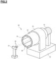
- the ball is shaped by a ball shaping device 10 illustrated in FIG. 2 .
- the ball shaping device 10 is known-technology, for instance, disclosed in Korean Patent Publication No. 10-2015-0051777 invented by the inventor of the present invention. Now, the configuration of the ball shaping device 10 and the step of shaping the ball will be described.
- the ball shaping device 10 includes: a rotary drum 12 rotatably mounted above a base 11 with a constant slope through a rotary support part 13; a driving part 14 for rotating the rotary drum 13; a polygonal part 16 formed on the inner face of an insertion hole 15 formed at one side of the rotary drum 13; and a spray part 17 for spraying water and a bonding agent to the insertion hole 15 of the rotary drum 13 by a nozzle 18 at a fixed rate.
- the feedstock powder is inserted into the insertion hole 15 of the rotary drum 13, and then, the rotary drum 13 is rotated.
- water and the bonding agent is sprayed into the insertion hole 15 by the nozzle 18 of the spray part 17 at the fixed rate.
- the water and the bonding agent sprayed into the insertion hole 15 are bonded with the feedstock powder in the form of waterdrops, and at the same time, and roll inside the rotary drum 13 of which the inner surface is coated with cement so as to be naturally shaped into a plurality of balls.
- the third step (S30) is a step of first drying the ball in order to form a through hole in the shaped ball, namely, is a step of properly drying moisture in order to form a through hole in the ball without the burning step.
- the surface of the ball is soft and flexible since moisture is removed.
- the fourth step (S40) is a step of forming the through hole in the first dried ball by a through hole forming device.
- a through hole forming device illustrated in FIGS. 3 and 4 is provided in order to form a through hole in the ball.
- the through hole forming device forms a through hole in the ball so as to increase the surface area of the ceramic ball 20 getting in contact with water.
- the through hole forming device includes a ball aligning part 100, a through hole forming part 200, and a discharge part 300 which are connected in a row with a fixed slope.
- the ball aligning part 100 is located at the uppermost part, and is a part to automatically transfer the balls dried in the third step (S30) to the through hole forming part 200.
- the ball aligning part 100 includes: a receiving part 110 for receiving the plurality of balls 20; a vibration generating part 120 mounted on the bottom surface of the receiving part 110 to generate vibration so as to automatically transfer the balls 20 received in the receiving part 110 to a guide part 130 formed at one side; and the guide part 130 for aligning the balls 20 received in the receiving part 110 in a row and transferring them to the through hole forming part 200.
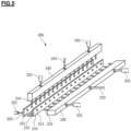
- the through hole forming part 200 is to form a through hole after temporarily fixing the balls transferred through the ball aligning part 100, and includes a fixing part 210, a moving part 220, a first perforating part 230, a second perforating part 240, and a stopper part.
- the fixing part 210 is formed in a L-shape, on which the received balls 20 are seated, and has a plurality of first holes 211 and a plurality of second holes 212 which are formed in the lateral surface and the bottom surface thereof at regular intervals.
- the first holes 211 and the second holes 212 are holes into which perforating pins are inserted, and are designed to face the centers of the balls 20 seated on the fixing part 210.
- the moving part 220 is mounted adjacent to one side of the fixing part 210, and fixes and supports or transfers the balls 20 seated on the fixing part 210 through a back-and-forth movement.
- the moving part 220 has third holes 221 formed at positions opposing to the first holes 211 of the fixing part 210, and performs the back-and-forth movement through a first cylinder 222.
- the first perforating part 230 is mounted at the other side of the fixing part 210, and forms a first through hole 21 in the ball 20 seated on the fixing part 210 by the back-and-forth movement as illustrated in FIG. 7 .
- the first perforating part 230 includes a plurality of first perforating pins 231 which are formed at one side thereof and are inserted into the first holes 211 of the fixing part 210 and the third holes 221 of the moving part 220, and moves in the back-and-forth direction through a second cylinder 232.
- the second perforating part 240 is mounted above the fixing part 210 and perforates a second through hole 22 in the ball 20 seated on the fixing part 210 by the back-and-forth movement as illustrated in FIG. 7 .
- the second perforating part 240 includes a plurality of second perforating pins 241 which are formed at one side thereof and are inserted into the second holes 212 of the fixing part 210, and moves in the back-and-forth direction through a third cylinder 242.
- the stopper part is mounted at both ends of the fixing part 210, and includes: a first stopper 251 mounted in a first space S1 between the guide part 130 of the ball aligning part 100 and the through hole forming part 200; and a second stopper 252 mounted in a second space S2 between the through hole forming part 200 and the discharge part 300.
- first stopper 251 moves upwards to open the first space S1
- second stopper 252 moves downwards to close the second space S2.
- the balls 20 transferred through the guide part 130 of the ball aligning part 100 are aligned on the fixing part 210 of the through hole forming part 200 in a row, but are blocked from being transferred to the discharge part 300 by the second stoper 252.
- the first stopper 251 moves downwards to close the first space S1 so that the balls 20 of a predetermined amount are seated on the fixing part 210.
- the through hole forming part 200 performs the step of forming the through hole in the ball 20.
- the second stopper 252 opens the second space S2 so that the balls 20 seated on the fixing part 210 are automatically transferred to the discharge part 300.
- the first cylinder 222 of the moving part 220 is operated to fix and support the ball 20 seated on the fixing part not to be moved.
- the first perforating part 230 moves backwards to its original position. After that, as illustrated in FIG. 6(c) , when the second perforating part 240 moves forwards by operation of the third cylinder 242, the second perforating pin 241 passes through the ball 20 and the second hole 212 of the fixing part 210 in order, so that the second through hole 22 is formed in the ball 20 as illustrated in FIG. 7 .
- the second perforating part 240 moves backwards to its original position.
- the first through hole 21 and the second through hole 22 formed in the ball 20 are in the shape of a cross, a first area part 21a and a second area part 22a respectively formed by the first through hole 21 and the second through hole 22 increase a cross-sectional area that the ceramic ball 20 gets in contact with water, and water flows through the first through hole 21 and the second through hole 22, so that contact efficiency between the ceramic ball and water is increased so as to increase washing efficiency.
- the fifth step (S50) is a step of second drying the ball in order to perfectly remove moisture when forming the through hole in the ball is completed, and is a preconditioning process for burning.
- the sixth step (S60) is a step of burning the dried ball at a constant temperature for predetermined time to finally manufacture a ceramic ball.
- the manufactured ceramic balls 20 are filled in a detergent dispensing device 30 for a dish washer as illustrated in FIG. 8 , or are filled in a detergent dispensing device 40 for a washing machine as illustrated in FIG. 9 .
Landscapes
- Engineering & Computer Science (AREA)
- Chemical & Material Sciences (AREA)
- Ceramic Engineering (AREA)
- Manufacturing & Machinery (AREA)
- Mechanical Engineering (AREA)
- Structural Engineering (AREA)
- Materials Engineering (AREA)
- Organic Chemistry (AREA)
- Life Sciences & Earth Sciences (AREA)
- Forests & Forestry (AREA)
- Inorganic Chemistry (AREA)
- Composite Materials (AREA)
- Devices For Post-Treatments, Processing, Supply, Discharge, And Other Processes (AREA)
Abstract
Description
- The present invention relates to a ceramic ball having a detergent function and a method for manufacturing a ceramic ball which is used in a washing machine or a dishwasher, and more particularly, to a ceramic ball having a detergent function and a method for manufacturing a ceramic ball, which can improve washing capacity since the ceramic ball is molded such that the surface area coming into contact with water gets wider, and can improve production efficiency and reduce the manufacturing cost since it is possible to manufacture ceramic balls continuously and automatically.
- In general, ceramic balls or washing balls having a detergent function are manufactured by ceramics being molded and burned in the form of a small ball, and are filled in an
insertion part 31 of adetergent dispensing device 30 for a dish washer as illustrated inFIG. 8 , or are filled in adetergent dispensing device 40 for a washing machine as illustrated inFIG. 9 . - The
detergent dispensing device 30 for the dish washer or thedetergent dispensing device 40 for the washing machine in which the ceramic balls (B) are filled is inserted into the dish washer or the washing machine, so that dishes or laundry are cleaned or washed without using general detergent due to antibacterial effect and purification action caused by far-infrared radiation and anions emitted from the ceramic balls (B). -
Korean Patent No. 10-1715275 - The conventional art relates to a ceramic ball having a detergent function and a method for manufacturing a ceramic ball which can improve washing capacity by widening the surface area of the ceramic ball getting in contact with water. That is, the conventional art provides an advantage to improve washing capacity by widening the surface area of the ceramic ball getting in contact with water.
- Moreover, the conventional art has a groove formed in the ceramic ball in order to widen the surface area of the ceramic ball, and uses a groove making machine in order to form the groove in the ceramic ball.
- However, because the groove making machine is a device to form a groove in the ceramic ball manually, it takes much time to form the groove in the ceramic ball. So, the groove making machine reduces production efficiency and increases the manufacturing cost.
- Furthermore, because water flowing into the groove formed in the ceramic ball is not discharged out easily, there is a limitation in contact efficiency that the ceramic ball gets in contact with water.
-
- Patent Document 1:
Korean Patent No. 10-1715275 - Patent Document 2:
Korean Patent No. 10-0932949 - Patent Document 3:
Korean Patent Publication No. 10-2011-0006390 - Accordingly, the present invention has been made to solve the above-mentioned problems occurring in the prior arts, and it is an object of the present invention to provide a ceramic ball having a detergent function and a method for manufacturing a ceramic ball, which can improve washing capacity since the ceramic ball is molded such that the surface area coming into contact with water gets wider, and can improve production efficiency and reduce the manufacturing cost since it is possible to manufacture ceramic balls continuously and automatically.
- It is another object of the present invention to provide a ceramic ball having a detergent function and a method for manufacturing a ceramic ball, which can improve contact efficiency that the ceramic ball gets in contact with water since water can pass through a through hole formed in the ceramic ball.
- To accomplish the above object, according to the present invention, there is provided a method for manufacturing a ceramic ball having a detergent function including: a first step of pulverizing and mixing raw materials in a fixed size to form feedstock powder; a second step of putting the feedstock powder formed through the first step into a ball shaping device and spraying water and a bonding agent to shape a ball; a third step of first drying the ball in order to form a through hole in the shaped ball; a fourth step of forming the through hole in the first dried ball by a through hole forming device; a fifth step of second drying the ball in order to perfectly remove moisture when forming the through hole in the ball is completed; and a sixth step of burning the dried ball to manufacture a ceramic ball.
- The through hole forming device includes a ball aligning part and a through hole forming part which are formed in a row with a fixed slope. The ball aligning part is located at the uppermost part and automatically transferring the balls dried in the third step to the through hole forming part using vibration, and the through hole forming part temporarily fixes the ball transferred by the ball aligning part and forming a predetermined through hole in the ball.
- Furthermore, the ball aligning part includes: a receiving part for receiving the plurality of balls; a vibration generating part mounted on the bottom surface of the receiving part to generate vibration so as to automatically transfer the balls received in the receiving part to a guide part formed at one side; and the guide part for aligning the balls received in the receiving part in a row and transferring them to the through hole forming part.
- Additionally, the through hole forming part includes: a fixing part which is formed in a L-shape on which the received balls are seated, and has a plurality of first holes and a plurality of second holes which are formed in the lateral surface and the bottom surface thereof at regular intervals; a moving part which is mounted adjacent to one side of the fixing part, fixes and supports or transfers the balls seated on the fixing part through a back-and-forth movement, and has third holes formed at positions opposing to the first holes of the fixing part; a first perforating part which is mounted at the other side of the fixing part, a plurality of first perforating pins which are formed at one side thereof and are inserted into the first holes of the fixing part and the third holes of the moving part, and forms a first through hole in the ball seated on the fixing part by the back-and-forth movement; and a second perforating part which is mounted above the fixing part, has a plurality of second perforating pins which are formed at one side thereof and are inserted into the second holes of the fixing part, and forms a second through hole in the ball seated on the fixing part by the back-and-forth movement.
- Moreover, the stopper part includes: a first stopper mounted in a first space between the guide part of the ball aligning part and the through hole forming part; and a second stopper mounted in a second space between the through hole forming part and the discharge part.
- Furthermore, in another aspect of the present invention, provided is a ceramic ball having a detergent function including: a first through hole and a second through hole formed in the shape of a cross; and a first area part and a second area part respectively formed by the first through hole and the second through hole so that a cross-sectional area between the ceramic ball and water is increased and water flows through the first through hole and the second through hole.
- According to an embodiment of the present invention, the ceramic ball having a detergent function and the method for manufacturing the ceramic ball can improve washing capacity since the ceramic ball is molded such that the surface area coming into contact with water gets wider, and can improve production efficiency and reduce the manufacturing cost since it is possible to manufacture ceramic balls continuously and automatically.
- According to an embodiment of the present invention, the ceramic ball having a detergent function and the method for manufacturing the ceramic ball can improve contact efficiency that the ceramic ball gets in contact with water since water can pass through a through hole formed in the ceramic ball.
- The above and other objects, features and advantages of the present invention will be apparent from the following detailed description of the preferred embodiments of the invention in conjunction with the accompanying drawings, in which:
-
FIG. 1 is a flow chart illustrating a method for manufacturing a ceramic ball having a detergent function according to a preferred embodiment of the present invention; -
FIG. 2 is a view illustrating a configuration of a ball molding machine applied to the present invention; -
FIG. 3 is a schematic side view illustrating a through hole forming device applied to the present invention; -
FIG. 4 is a perspective view illustrating the through hole forming device applied to the present invention; -
FIG. 5 is a view illustrating a configuration of the through hole forming device applied to the present invention; -
FIGS. 6(a) to 6(c) are sectional views illustrating the through hole forming device to show a through hole forming process according to the present invention; -
FIGS. 7(a) and 7(b) are respectively a perspective view and a sectional view of a ceramic ball having a detergent function according to the present invention; -
FIG. 8 is a view illustrating a configuration of a detergent dispensing device for a dish washer to which the ceramic ball of the present invention is applied; and -
FIG. 9 is a view illustrating a configuration of a detergent dispensing device for a washing machine to which the ceramic ball of the present invention is applied. - Hereinafter, preferred embodiments of the present invention will be described in detail with reference to the accompanying drawings.
- In the following description, the same components will be designated by the same reference numerals although they are shown in different drawings. Further, in the following description of the present invention, a detailed description of known functions and configurations incorporated herein will be omitted when it may make the subject matter of the present invention rather unclear.
-
FIG. 1 is a flow chart illustrating a method for manufacturing a ceramic ball having a detergent function according to a preferred embodiment of the present invention. - As illustrated in the drawing, the method for manufacturing a ceramic ball having a detergent function according to the embodiment of the present invention includes: a first step (S10) of pulverizing and mixing raw materials in a fixed size to form feedstock powder; a second step (S20) of putting the feedstock powder formed through the first step into a ball shaping device and spraying water and a bonding agent to shape a ball; a third step (S30) of first drying the ball in order to form a through hole in the shaped ball; a fourth step (S40) of forming the through hole in the first dried ball by a through hole forming device; a fifth step (S50) of second drying the ball in order to perfectly remove moisture when forming the through hole in the ball is completed; and a sixth step (S60) of burning the dried ball to manufacture a ceramic ball.
- The first step (S10) is a step of pulverizing and mixing raw materials into a fixed size to form feedstock powder. The feedstock powder mainly includes silicon oxide (SiO2), aluminum oxide (Al2O3), and zirconium oxide (ZrO2).
- The second step (S20) is a step of putting the feedstock powder formed through the first step into a ball shaping device and spraying water and a bonding agent to shape a ball. The ball is shaped by a
ball shaping device 10 illustrated inFIG. 2 . - The
ball shaping device 10 is known-technology, for instance, disclosed inKorean Patent Publication No. 10-2015-0051777 ball shaping device 10 and the step of shaping the ball will be described. - The
ball shaping device 10 includes: arotary drum 12 rotatably mounted above abase 11 with a constant slope through arotary support part 13; a drivingpart 14 for rotating therotary drum 13; apolygonal part 16 formed on the inner face of aninsertion hole 15 formed at one side of therotary drum 13; and aspray part 17 for spraying water and a bonding agent to theinsertion hole 15 of therotary drum 13 by anozzle 18 at a fixed rate. - Now, a process of shaping a ball will be described. The feedstock powder is inserted into the
insertion hole 15 of therotary drum 13, and then, therotary drum 13 is rotated. - After that, water and the bonding agent is sprayed into the
insertion hole 15 by thenozzle 18 of thespray part 17 at the fixed rate. - The water and the bonding agent sprayed into the
insertion hole 15 are bonded with the feedstock powder in the form of waterdrops, and at the same time, and roll inside therotary drum 13 of which the inner surface is coated with cement so as to be naturally shaped into a plurality of balls. - Moreover, strength of the balls increases since the balls are formed while being bumped against the
polygonal part 16. - The third step (S30) is a step of first drying the ball in order to form a through hole in the shaped ball, namely, is a step of properly drying moisture in order to form a through hole in the ball without the burning step.
- Preferably, it takes two to three hours to dry moisture. In this instance, the surface of the ball is soft and flexible since moisture is removed.
- The fourth step (S40) is a step of forming the through hole in the first dried ball by a through hole forming device. A through hole forming device illustrated in
FIGS. 3 and 4 is provided in order to form a through hole in the ball. - The through hole forming device forms a through hole in the ball so as to increase the surface area of the
ceramic ball 20 getting in contact with water. - The through hole forming device includes a
ball aligning part 100, a throughhole forming part 200, and adischarge part 300 which are connected in a row with a fixed slope. - The
ball aligning part 100 is located at the uppermost part, and is a part to automatically transfer the balls dried in the third step (S30) to the throughhole forming part 200. Theball aligning part 100 includes: a receivingpart 110 for receiving the plurality ofballs 20; avibration generating part 120 mounted on the bottom surface of the receivingpart 110 to generate vibration so as to automatically transfer theballs 20 received in the receivingpart 110 to aguide part 130 formed at one side; and theguide part 130 for aligning theballs 20 received in the receivingpart 110 in a row and transferring them to the throughhole forming part 200. - As illustrated in
FIG. 5 , the throughhole forming part 200 is to form a through hole after temporarily fixing the balls transferred through theball aligning part 100, and includes a fixingpart 210, a movingpart 220, a first perforatingpart 230, asecond perforating part 240, and a stopper part. - The fixing
part 210 is formed in a L-shape, on which the receivedballs 20 are seated, and has a plurality offirst holes 211 and a plurality ofsecond holes 212 which are formed in the lateral surface and the bottom surface thereof at regular intervals. - The
first holes 211 and thesecond holes 212 are holes into which perforating pins are inserted, and are designed to face the centers of theballs 20 seated on the fixingpart 210. - The moving
part 220 is mounted adjacent to one side of the fixingpart 210, and fixes and supports or transfers theballs 20 seated on the fixingpart 210 through a back-and-forth movement. - The moving
part 220 hasthird holes 221 formed at positions opposing to thefirst holes 211 of the fixingpart 210, and performs the back-and-forth movement through afirst cylinder 222. - The
first perforating part 230 is mounted at the other side of the fixingpart 210, and forms a first throughhole 21 in theball 20 seated on the fixingpart 210 by the back-and-forth movement as illustrated inFIG. 7 . - The
first perforating part 230 includes a plurality of first perforating pins 231 which are formed at one side thereof and are inserted into thefirst holes 211 of the fixingpart 210 and thethird holes 221 of the movingpart 220, and moves in the back-and-forth direction through asecond cylinder 232. - The
second perforating part 240 is mounted above the fixingpart 210 and perforates a second throughhole 22 in theball 20 seated on the fixingpart 210 by the back-and-forth movement as illustrated inFIG. 7 . - The
second perforating part 240 includes a plurality of second perforating pins 241 which are formed at one side thereof and are inserted into thesecond holes 212 of the fixingpart 210, and moves in the back-and-forth direction through athird cylinder 242. - The stopper part is mounted at both ends of the fixing
part 210, and includes: afirst stopper 251 mounted in a first space S1 between theguide part 130 of theball aligning part 100 and the throughhole forming part 200; and asecond stopper 252 mounted in a second space S2 between the throughhole forming part 200 and thedischarge part 300. - Now, operations of the
first stopper 251 and thesecond stopper 252 will be described. First, thefirst stopper 251 moves upwards to open the first space S1, and thesecond stopper 252 moves downwards to close the second space S2. - Therefore, the
balls 20 transferred through theguide part 130 of theball aligning part 100 are aligned on the fixingpart 210 of the throughhole forming part 200 in a row, but are blocked from being transferred to thedischarge part 300 by thesecond stoper 252. - In the above state, the
first stopper 251 moves downwards to close the first space S1 so that theballs 20 of a predetermined amount are seated on the fixingpart 210. - When the
balls 20 are seated on the fixingpart 210, the throughhole forming part 200 performs the step of forming the through hole in theball 20. When the step of forming the through hole is finished, thesecond stopper 252 opens the second space S2 so that theballs 20 seated on the fixingpart 210 are automatically transferred to thedischarge part 300. - Next, the operation that the
second stopper 252 closes the second space S2 and thefirst stopper 251 opens the first space S1 is repeated. - Meanwhile, referring to
FIG. 6 , the step of forming the through hole in theball 20 by the throughhole forming part 200 is described. - First, when the
ball 20 is aligned and seated on the fixingpart 210, as illustrated inFIG. 6(a) , thefirst cylinder 222 of the movingpart 220 is operated to fix and support theball 20 seated on the fixing part not to be moved. - Next, as illustrated in
FIG. 6(b) , when the first perforatingpart 230 moves forwards by operation of thesecond cylinder 232, thefirst perforating pin 231 passes through thefirst hole 211 of the fixingpart 210, theball 20, and thethird hole 221 of the movingpart 220 in order, so that the first throughhole 21 is formed in theball 20 as illustrated inFIG. 7 . - When the first through
hole 21 is formed in theball 20, the first perforatingpart 230 moves backwards to its original position. After that, as illustrated inFIG. 6(c) , when the second perforatingpart 240 moves forwards by operation of thethird cylinder 242, thesecond perforating pin 241 passes through theball 20 and thesecond hole 212 of the fixingpart 210 in order, so that the second throughhole 22 is formed in theball 20 as illustrated inFIG. 7 . - When the second through
hole 22 is formed in theball 20, the second perforatingpart 240 moves backwards to its original position. - The first through
hole 21 and the second throughhole 22 formed in theball 20 are in the shape of a cross, afirst area part 21a and asecond area part 22a respectively formed by the first throughhole 21 and the second throughhole 22 increase a cross-sectional area that theceramic ball 20 gets in contact with water, and water flows through the first throughhole 21 and the second throughhole 22, so that contact efficiency between the ceramic ball and water is increased so as to increase washing efficiency. - The fifth step (S50) is a step of second drying the ball in order to perfectly remove moisture when forming the through hole in the ball is completed, and is a preconditioning process for burning.
- The sixth step (S60) is a step of burning the dried ball at a constant temperature for predetermined time to finally manufacture a ceramic ball.
- Therefore, the manufactured
ceramic balls 20 are filled in adetergent dispensing device 30 for a dish washer as illustrated inFIG. 8 , or are filled in adetergent dispensing device 40 for a washing machine as illustrated inFIG. 9 . - While the present invention has been described by the limited embodiments and the drawings as described above, the present invention is not limited by the above and various modifications and variations are possible to those skilled in the art from the above description.
Claims (5)
- A method for manufacturing a ceramic ball having a detergent function comprising:- a first step of pulverizing and mixing raw materials in a fixed size to form feedstock powder;- a second step of putting the feedstock powder formed through the first step into a ball shaping device and spraying water and a bonding agent to shape a ball;- a third step of first drying the ball in order to form a through hole in the shaped ball;- a fourth step of forming the through hole in the first dried ball by a through hole forming device;- a fifth step of second drying the ball in order to perfectly remove moisture when forming the through hole in the ball is completed; and- a sixth step of burning the dried ball to manufacture a ceramic ball,- wherein the through hole forming device includes a ball aligning part and a through hole forming part which are formed in a row with a fixed slope, the ball aligning part being located at the uppermost part and automatically transferring the balls dried in the third step to the through hole forming part using vibration, and the through hole forming part temporarily fixing the ball transferred by the ball aligning part and forming a predetermined through hole in the ball.
- The method according to claim 1, wherein the ball aligning part includes: a receiving part for receiving the plurality of balls; a vibration generating part mounted on the bottom surface of the receiving part to generate vibration so as to automatically transfer the balls received in the receiving part to a guide part formed at one side; and the guide part for aligning the balls received in the receiving part in a row and transferring them to the through hole forming part.
- The method according to claim 1, wherein the through hole forming part includes:- a fixing part which is formed in a L-shape on which the received balls are seated, and has a plurality of first holes and a plurality of second holes which are formed in the lateral surface and the bottom surface thereof at regular intervals;- a moving part which is mounted adjacent to one side of the fixing part, fixes and supports or transfers the balls seated on the fixing part through a back-and-forth movement, and has third holes formed at positions opposing to the first holes of the fixing part;- a first perforating part which is mounted at the other side of the fixing part, a plurality of first perforating pins which are formed at one side thereof and are inserted into the first holes of the fixing part and the third holes of the moving part, and forms a first through hole in the ball seated on the fixing part by the back-and-forth movement; and- a second perforating part which is mounted above the fixing part, has a plurality of second perforating pins which are formed at one side thereof and are inserted into the second holes of the fixing part, and forms a second through hole in the ball seated on the fixing part by the back-and-forth movement.
- The method according to claim 3, wherein the stopper part includes: a first stopper mounted in a first space between the guide part of the ball aligning part and the through hole forming part; and a second stopper mounted in a second space between the through hole forming part and the discharge part.
- A ceramic ball having a detergent function, which is manufactured by the manufacturing method according to claims 1 to 4, the ceramic ball comprising:- a first through hole and a second through hole formed in the shape of a cross; and- a first area part and a second area part respectively formed by the first through hole and the second through hole so that a cross-sectional area between the ceramic ball and water is increased and water flows through the first through hole and the second through hole.
Priority Applications (1)
| Application Number | Priority Date | Filing Date | Title |
|---|---|---|---|
| EP21020564.7A EP4180196B1 (en) | 2021-11-11 | 2021-11-11 | Manufacturing of a ceramic ball having detergent function |
Applications Claiming Priority (1)
| Application Number | Priority Date | Filing Date | Title |
|---|---|---|---|
| EP21020564.7A EP4180196B1 (en) | 2021-11-11 | 2021-11-11 | Manufacturing of a ceramic ball having detergent function |
Publications (2)
| Publication Number | Publication Date |
|---|---|
| EP4180196A1 true EP4180196A1 (en) | 2023-05-17 |
| EP4180196B1 EP4180196B1 (en) | 2025-10-22 |
Family
ID=78820450
Family Applications (1)
| Application Number | Title | Priority Date | Filing Date |
|---|---|---|---|
| EP21020564.7A Active EP4180196B1 (en) | 2021-11-11 | 2021-11-11 | Manufacturing of a ceramic ball having detergent function |
Country Status (1)
| Country | Link |
|---|---|
| EP (1) | EP4180196B1 (en) |
Citations (6)
| Publication number | Priority date | Publication date | Assignee | Title |
|---|---|---|---|---|
| KR100932949B1 (en) | 2008-07-14 | 2009-12-21 | 한국기계연구원 | Porous ceramic ball with hierarchical pore structure and its manufacturing method |
| KR20110006390A (en) | 2009-07-14 | 2011-01-20 | 이정우 | Porous Ceramic Ball Manufacturing Method |
| KR20150051777A (en) | 2013-11-05 | 2015-05-13 | (주) 대은글로벌솔루션 | Manufacturing method for ceramic ball having detergent function |
| CN205146236U (en) * | 2015-11-20 | 2016-04-13 | 萍乡市建威化工填料助剂有限公司 | Aluminium oxide trompil ball |
| CN106431263A (en) * | 2016-09-24 | 2017-02-22 | 甘肃华晨生态治理有限公司 | Round-ball-shaped diatomite light-weight through hole porcelain granule with air purification function |
| KR101715275B1 (en) | 2016-07-06 | 2017-03-17 | (주) 대은글로벌솔루션 | Ceramic ball having detergent function and manufacturing method thereof |
-
2021
- 2021-11-11 EP EP21020564.7A patent/EP4180196B1/en active Active
Patent Citations (6)
| Publication number | Priority date | Publication date | Assignee | Title |
|---|---|---|---|---|
| KR100932949B1 (en) | 2008-07-14 | 2009-12-21 | 한국기계연구원 | Porous ceramic ball with hierarchical pore structure and its manufacturing method |
| KR20110006390A (en) | 2009-07-14 | 2011-01-20 | 이정우 | Porous Ceramic Ball Manufacturing Method |
| KR20150051777A (en) | 2013-11-05 | 2015-05-13 | (주) 대은글로벌솔루션 | Manufacturing method for ceramic ball having detergent function |
| CN205146236U (en) * | 2015-11-20 | 2016-04-13 | 萍乡市建威化工填料助剂有限公司 | Aluminium oxide trompil ball |
| KR101715275B1 (en) | 2016-07-06 | 2017-03-17 | (주) 대은글로벌솔루션 | Ceramic ball having detergent function and manufacturing method thereof |
| CN106431263A (en) * | 2016-09-24 | 2017-02-22 | 甘肃华晨生态治理有限公司 | Round-ball-shaped diatomite light-weight through hole porcelain granule with air purification function |
Also Published As
| Publication number | Publication date |
|---|---|
| EP4180196B1 (en) | 2025-10-22 |
Similar Documents
| Publication | Publication Date | Title |
|---|---|---|
| US11322345B2 (en) | Post-CMP cleaning and apparatus | |
| EP4180196B1 (en) | Manufacturing of a ceramic ball having detergent function | |
| US12351777B2 (en) | Ceramic ball having detergent function and manufacturing method thereof | |
| KR100571640B1 (en) | Sponge Roller for Cleaning | |
| EP2292134A1 (en) | Dishwasher with moving water nozzles | |
| US20200258737A1 (en) | Substrate cleaning method and substrate cleaning apparatus | |
| JP4072333B2 (en) | Tableware cleaning equipment | |
| TW201628724A (en) | Substrate cleaning roller, substrate cleaning device and substrate cleaning method | |
| CA1075541A (en) | Method and apparatus for lining a cathode ray tube with an electrically conductive coating having a sharply defined boundary | |
| ITMI992054A1 (en) | REVOLVING SPRAYER FOR DISHWASHER EQUIPPED WITH DEVICE FOR HORIZONTAL MOVEMENT | |
| JP2003093978A (en) | Method and apparatus for cleaning carrier plate | |
| US5488965A (en) | Washing nozzle utilized in dishwashing machine | |
| CN204885113U (en) | Wafer cleaning brush and wafer belt cleaning device | |
| KR101584427B1 (en) | Brush unit for cleaning wafer | |
| KR20210094464A (en) | Substrate cleaning apparatus and substrate cleaning method | |
| KR102569547B1 (en) | Ceramic ball having detergent function and manufacturing method thereof | |
| US5137440A (en) | Brush cleaning mechanism for soap molding machines | |
| CN211079378U (en) | Electroplating rings and electroplating equipment | |
| JP6122684B2 (en) | Substrate processing apparatus and manufacturing method of processing substrate | |
| KR100828280B1 (en) | Cleaning chamber for spin scrubber and wafer cleaning method using the same | |
| CN209551724U (en) | Mechanical arm and manipulator and polissoir with it | |
| KR100479507B1 (en) | Method of making vacuum suction nozzle tip | |
| KR19990009660A (en) | Back cleaning device for semiconductor wafer, wafer cleaning device and wafer cleaning method using the same | |
| KR20050071062A (en) | Srd for cmp equipment | |
| KR102650110B1 (en) | Cleaning brush and bread pan cleaning device using thereof |
Legal Events
| Date | Code | Title | Description |
|---|---|---|---|
| PUAI | Public reference made under article 153(3) epc to a published international application that has entered the european phase |
Free format text: ORIGINAL CODE: 0009012 |
|
| STAA | Information on the status of an ep patent application or granted ep patent |
Free format text: STATUS: THE APPLICATION HAS BEEN PUBLISHED |
|
| AK | Designated contracting states |
Kind code of ref document: A1 Designated state(s): AL AT BE BG CH CY CZ DE DK EE ES FI FR GB GR HR HU IE IS IT LI LT LU LV MC MK MT NL NO PL PT RO RS SE SI SK SM TR |
|
| STAA | Information on the status of an ep patent application or granted ep patent |
Free format text: STATUS: REQUEST FOR EXAMINATION WAS MADE |
|
| 17P | Request for examination filed |
Effective date: 20231129 |
|
| RBV | Designated contracting states (corrected) |
Designated state(s): AL AT BE BG CH CY CZ DE DK EE ES FI FR GB GR HR HU IE IS IT LI LT LU LV MC MK MT NL NO PL PT RO RS SE SI SK SM TR |
|
| RIC1 | Information provided on ipc code assigned before grant |
Ipc: D06F 39/02 20060101ALN20250409BHEP Ipc: B26F 1/24 20060101ALI20250409BHEP Ipc: C04B 35/626 20060101ALI20250409BHEP Ipc: C04B 35/14 20060101ALI20250409BHEP Ipc: B26D 7/06 20060101ALI20250409BHEP Ipc: B26D 7/01 20060101ALI20250409BHEP Ipc: C04B 35/486 20060101ALI20250409BHEP Ipc: C04B 35/111 20060101ALI20250409BHEP Ipc: B28B 11/24 20060101ALI20250409BHEP Ipc: B28B 7/18 20060101ALI20250409BHEP Ipc: B28B 1/48 20060101AFI20250409BHEP |
|
| GRAP | Despatch of communication of intention to grant a patent |
Free format text: ORIGINAL CODE: EPIDOSNIGR1 |
|
| STAA | Information on the status of an ep patent application or granted ep patent |
Free format text: STATUS: GRANT OF PATENT IS INTENDED |
|
| RIC1 | Information provided on ipc code assigned before grant |
Ipc: D06F 39/02 20060101ALN20250422BHEP Ipc: B26F 1/24 20060101ALI20250422BHEP Ipc: C04B 35/626 20060101ALI20250422BHEP Ipc: C04B 35/14 20060101ALI20250422BHEP Ipc: B26D 7/06 20060101ALI20250422BHEP Ipc: B26D 7/01 20060101ALI20250422BHEP Ipc: C04B 35/486 20060101ALI20250422BHEP Ipc: C04B 35/111 20060101ALI20250422BHEP Ipc: B28B 11/24 20060101ALI20250422BHEP Ipc: B28B 7/18 20060101ALI20250422BHEP Ipc: B28B 1/48 20060101AFI20250422BHEP |
|
| INTG | Intention to grant announced |
Effective date: 20250516 |
|
| RAP3 | Party data changed (applicant data changed or rights of an application transferred) |
Owner name: DAEEUN GLOBAL SOLUTION CO., LTD. |
|
| GRAS | Grant fee paid |
Free format text: ORIGINAL CODE: EPIDOSNIGR3 |
|
| GRAA | (expected) grant |
Free format text: ORIGINAL CODE: 0009210 |
|
| STAA | Information on the status of an ep patent application or granted ep patent |
Free format text: STATUS: THE PATENT HAS BEEN GRANTED |
|
| AK | Designated contracting states |
Kind code of ref document: B1 Designated state(s): AL AT BE BG CH CY CZ DE DK EE ES FI FR GB GR HR HU IE IS IT LI LT LU LV MC MK MT NL NO PL PT RO RS SE SI SK SM TR |
|
| REG | Reference to a national code |
Ref country code: CH Ref legal event code: F10 Free format text: ST27 STATUS EVENT CODE: U-0-0-F10-F00 (AS PROVIDED BY THE NATIONAL OFFICE) Effective date: 20251022 Ref country code: GB Ref legal event code: FG4D |
|
| REG | Reference to a national code |
Ref country code: IE Ref legal event code: FG4D |
|
| REG | Reference to a national code |
Ref country code: DE Ref legal event code: R096 Ref document number: 602021040688 Country of ref document: DE |
|
| PGFP | Annual fee paid to national office [announced via postgrant information from national office to epo] |
Ref country code: DE Payment date: 20251202 Year of fee payment: 5 |
|
| PGFP | Annual fee paid to national office [announced via postgrant information from national office to epo] |
Ref country code: GB Payment date: 20251201 Year of fee payment: 5 |
|
| PGFP | Annual fee paid to national office [announced via postgrant information from national office to epo] |
Ref country code: AT Payment date: 20260113 Year of fee payment: 5 |
|
| PGFP | Annual fee paid to national office [announced via postgrant information from national office to epo] |
Ref country code: FR Payment date: 20251126 Year of fee payment: 5 |
|
| REG | Reference to a national code |
Ref country code: NL Ref legal event code: MP Effective date: 20251022 |
|
| PG25 | Lapsed in a contracting state [announced via postgrant information from national office to epo] |
Ref country code: NL Free format text: LAPSE BECAUSE OF FAILURE TO SUBMIT A TRANSLATION OF THE DESCRIPTION OR TO PAY THE FEE WITHIN THE PRESCRIBED TIME-LIMIT Effective date: 20251022 |
|
| PG25 | Lapsed in a contracting state [announced via postgrant information from national office to epo] |
Ref country code: ES Free format text: LAPSE BECAUSE OF FAILURE TO SUBMIT A TRANSLATION OF THE DESCRIPTION OR TO PAY THE FEE WITHIN THE PRESCRIBED TIME-LIMIT Effective date: 20251022 |
|
| REG | Reference to a national code |
Ref country code: LT Ref legal event code: MG9D |
|
| PG25 | Lapsed in a contracting state [announced via postgrant information from national office to epo] |
Ref country code: NO Free format text: LAPSE BECAUSE OF FAILURE TO SUBMIT A TRANSLATION OF THE DESCRIPTION OR TO PAY THE FEE WITHIN THE PRESCRIBED TIME-LIMIT Effective date: 20260122 |
|
| PG25 | Lapsed in a contracting state [announced via postgrant information from national office to epo] |
Ref country code: AT Free format text: LAPSE BECAUSE OF FAILURE TO SUBMIT A TRANSLATION OF THE DESCRIPTION OR TO PAY THE FEE WITHIN THE PRESCRIBED TIME-LIMIT Effective date: 20251022 Ref country code: FI Free format text: LAPSE BECAUSE OF FAILURE TO SUBMIT A TRANSLATION OF THE DESCRIPTION OR TO PAY THE FEE WITHIN THE PRESCRIBED TIME-LIMIT Effective date: 20251022 Ref country code: HR Free format text: LAPSE BECAUSE OF FAILURE TO SUBMIT A TRANSLATION OF THE DESCRIPTION OR TO PAY THE FEE WITHIN THE PRESCRIBED TIME-LIMIT Effective date: 20251022 |
|
| PGFP | Annual fee paid to national office [announced via postgrant information from national office to epo] |
Ref country code: IT Payment date: 20260129 Year of fee payment: 5 |
|
| REG | Reference to a national code |
Ref country code: AT Ref legal event code: MK05 Ref document number: 1848782 Country of ref document: AT Kind code of ref document: T Effective date: 20251022 |
|
| PG25 | Lapsed in a contracting state [announced via postgrant information from national office to epo] |
Ref country code: RS Free format text: LAPSE BECAUSE OF FAILURE TO SUBMIT A TRANSLATION OF THE DESCRIPTION OR TO PAY THE FEE WITHIN THE PRESCRIBED TIME-LIMIT Effective date: 20260122 |
|
| PG25 | Lapsed in a contracting state [announced via postgrant information from national office to epo] |
Ref country code: IS Free format text: LAPSE BECAUSE OF FAILURE TO SUBMIT A TRANSLATION OF THE DESCRIPTION OR TO PAY THE FEE WITHIN THE PRESCRIBED TIME-LIMIT Effective date: 20260222 |
|
| PG25 | Lapsed in a contracting state [announced via postgrant information from national office to epo] |
Ref country code: PT Free format text: LAPSE BECAUSE OF FAILURE TO SUBMIT A TRANSLATION OF THE DESCRIPTION OR TO PAY THE FEE WITHIN THE PRESCRIBED TIME-LIMIT Effective date: 20260223 |
|
| PG25 | Lapsed in a contracting state [announced via postgrant information from national office to epo] |
Ref country code: PL Free format text: LAPSE BECAUSE OF FAILURE TO SUBMIT A TRANSLATION OF THE DESCRIPTION OR TO PAY THE FEE WITHIN THE PRESCRIBED TIME-LIMIT Effective date: 20251022 |
|
| PG25 | Lapsed in a contracting state [announced via postgrant information from national office to epo] |
Ref country code: LV Free format text: LAPSE BECAUSE OF FAILURE TO SUBMIT A TRANSLATION OF THE DESCRIPTION OR TO PAY THE FEE WITHIN THE PRESCRIBED TIME-LIMIT Effective date: 20251022 |