EP4179891B1 - Elektronische rauchvorrichtung und verfahren zur herstellung davon - Google Patents
Elektronische rauchvorrichtung und verfahren zur herstellung davon Download PDFInfo
- Publication number
- EP4179891B1 EP4179891B1 EP23150933.2A EP23150933A EP4179891B1 EP 4179891 B1 EP4179891 B1 EP 4179891B1 EP 23150933 A EP23150933 A EP 23150933A EP 4179891 B1 EP4179891 B1 EP 4179891B1
- Authority
- EP
- European Patent Office
- Prior art keywords
- insert
- housing sleeve
- atomizer
- smoking device
- electronic smoking
- Prior art date
- Legal status (The legal status is an assumption and is not a legal conclusion. Google has not performed a legal analysis and makes no representation as to the accuracy of the status listed.)
- Active
Links
Images

Classifications
-
- A—HUMAN NECESSITIES
- A61—MEDICAL OR VETERINARY SCIENCE; HYGIENE
- A61M—DEVICES FOR INTRODUCING MEDIA INTO, OR ONTO, THE BODY; DEVICES FOR TRANSDUCING BODY MEDIA OR FOR TAKING MEDIA FROM THE BODY; DEVICES FOR PRODUCING OR ENDING SLEEP OR STUPOR
- A61M15/00—Inhalators
- A61M15/06—Inhaling appliances shaped like cigars, cigarettes or pipes
-
- A—HUMAN NECESSITIES
- A24—TOBACCO; CIGARS; CIGARETTES; SIMULATED SMOKING DEVICES; SMOKERS' REQUISITES
- A24F—SMOKERS' REQUISITES; MATCH BOXES; SIMULATED SMOKING DEVICES
- A24F40/00—Electrically operated smoking devices; Component parts thereof; Manufacture thereof; Maintenance or testing thereof; Charging means specially adapted therefor
- A24F40/40—Constructional details, e.g. connection of cartridges and battery parts
-
- A—HUMAN NECESSITIES
- A24—TOBACCO; CIGARS; CIGARETTES; SIMULATED SMOKING DEVICES; SMOKERS' REQUISITES
- A24F—SMOKERS' REQUISITES; MATCH BOXES; SIMULATED SMOKING DEVICES
- A24F40/00—Electrically operated smoking devices; Component parts thereof; Manufacture thereof; Maintenance or testing thereof; Charging means specially adapted therefor
- A24F40/50—Control or monitoring
-
- A—HUMAN NECESSITIES
- A24—TOBACCO; CIGARS; CIGARETTES; SIMULATED SMOKING DEVICES; SMOKERS' REQUISITES
- A24F—SMOKERS' REQUISITES; MATCH BOXES; SIMULATED SMOKING DEVICES
- A24F40/00—Electrically operated smoking devices; Component parts thereof; Manufacture thereof; Maintenance or testing thereof; Charging means specially adapted therefor
- A24F40/70—Manufacture
-
- A—HUMAN NECESSITIES
- A24—TOBACCO; CIGARS; CIGARETTES; SIMULATED SMOKING DEVICES; SMOKERS' REQUISITES
- A24F—SMOKERS' REQUISITES; MATCH BOXES; SIMULATED SMOKING DEVICES
- A24F40/00—Electrically operated smoking devices; Component parts thereof; Manufacture thereof; Maintenance or testing thereof; Charging means specially adapted therefor
- A24F40/90—Arrangements or methods specially adapted for charging batteries thereof
-
- H—ELECTRICITY
- H05—ELECTRIC TECHNIQUES NOT OTHERWISE PROVIDED FOR
- H05B—ELECTRIC HEATING; ELECTRIC LIGHT SOURCES NOT OTHERWISE PROVIDED FOR; CIRCUIT ARRANGEMENTS FOR ELECTRIC LIGHT SOURCES, IN GENERAL
- H05B1/00—Details of electric heating devices
- H05B1/02—Automatic switching arrangements specially adapted to apparatus ; Control of heating devices
- H05B1/0202—Switches
-
- H—ELECTRICITY
- H05—ELECTRIC TECHNIQUES NOT OTHERWISE PROVIDED FOR
- H05B—ELECTRIC HEATING; ELECTRIC LIGHT SOURCES NOT OTHERWISE PROVIDED FOR; CIRCUIT ARRANGEMENTS FOR ELECTRIC LIGHT SOURCES, IN GENERAL
- H05B1/00—Details of electric heating devices
- H05B1/02—Automatic switching arrangements specially adapted to apparatus ; Control of heating devices
- H05B1/0227—Applications
- H05B1/023—Industrial applications
- H05B1/0244—Heating of fluids
-
- H—ELECTRICITY
- H05—ELECTRIC TECHNIQUES NOT OTHERWISE PROVIDED FOR
- H05B—ELECTRIC HEATING; ELECTRIC LIGHT SOURCES NOT OTHERWISE PROVIDED FOR; CIRCUIT ARRANGEMENTS FOR ELECTRIC LIGHT SOURCES, IN GENERAL
- H05B3/00—Ohmic-resistance heating
- H05B3/0014—Devices wherein the heating current flows through particular resistances
-
- A—HUMAN NECESSITIES
- A24—TOBACCO; CIGARS; CIGARETTES; SIMULATED SMOKING DEVICES; SMOKERS' REQUISITES
- A24F—SMOKERS' REQUISITES; MATCH BOXES; SIMULATED SMOKING DEVICES
- A24F40/00—Electrically operated smoking devices; Component parts thereof; Manufacture thereof; Maintenance or testing thereof; Charging means specially adapted therefor
- A24F40/10—Devices using liquid inhalable precursors
Definitions
- the invention relates to an electronic smoking device, in particular an electronic cigarette, and a process of manufacturing such an electronic smoking device.
- An electronic smoking device e.g. designed as an electronic cigarette, generally comprises an elongate housing accommodating an electric power source (a battery, which often is rechargeable), an electrically activatable atomizer adapted to atomize a liquid supplied from a capsule mounted at the electronic cigarette, and control electronics, e.g. a switch (in the form of a button or a sensor which senses a user's puff) and related circuitry. Actuation of the switch (e.g. by pressing the button or upon detection of a user's puff at a mouthpiece) causes a heater in the atomizer to be powered for a certain time.
- the action of the atomizer is referred to "atomizing” and the related product is referred to as an "aerosol", irrespective of its composition, which might include gaseous and smoke constituents.
- EP 2 443 946 A1 discloses an electronic cigarette and a capsule containing a liquid to be atomized (or evaporated) by an atomizer.
- the capsule comprises a shell which is sealed at one end by a puncturable membrane.
- the capsule is inserted into a soft sleeve mouth piece and attached to the end of a tube accommodating the atomizer.
- a spike provided at the end of a metal wick pierces the membrane, and the liquid of the capsule is guided by the wick to the atomizer.
- the atomizer is activated, an aerosol is generated and the aerosol passes through some ducts provided at the exterior surface of the capsule to reach an end opening where it can be sucked by the consumer via the mouthpiece.
- US 2011/0304282 A1 describes a power supply section for an electronic cigarette.
- This section comprises an elongate housing sleeve, which accommodates a rechargeable battery, a puff sensor for detecting an aerosol inhaling puff of a user, and control electronics connected to the puff sensor and adapted to control the heater of an atomizer.
- a connector provides mechanical support for a portion of the electronic cigarette, which comprises the atomizer and holds a capsule containing a liquid to be atomized.
- the connector includes electrical connections for the atomizer.
- an electronic smoking device like a battery, a puff sensor and/or control electronics
- an elongate housing sleeve e.g. as known from US 2011/0304282 A1
- the assemblage can therefore be time consuming and potentially involves some risk of damage to the components.
- US 2008/0257367 A1 discloses an electronic cigarette with a housing sleeve to linearly accommodate cigarette components.
- EP 1 989 946 A1 discloses a smoking device comprising a first device with an accumulator, a heating device, a first air inlet as well as a first air outlet and a second device with an agent, a second air inlet as well as a second air outlet, wherein an interface for connecting said first device and second device is provided so that said first air outlet is connected to said second air inlet.
- CN 202 456 412 U discloses a electronic cigarette in which the battery and the atomizer elements are arranged on an insert within a housing sleeve.
- the object of the invention is to provide an electronic smoking device, which can be manufactured in a more cost-effective and more reliable way, as well as a related process of manufacturing an electronic smoking device.
- Claim 13 is directed to a process of manufacturing such an electronic smoking device.
- an electronic smoking device comprising an elongate housing sleeve having a first end and a second end, an atomizer section provided in addition to the housing sleeve such that an electrically activatable atomizer including an electric heater and a reservoir containing a liquid are arranged in the atomizer section and are not accommodated in the housing sleeve.
- the housing sleeve contains an elongate insert that is configured to fit into the housing sleeve via an aperture in one of the ends of the housing sleeve.
- the following components are mounted on the insert: a rechargeable battery as an electric power source adapted to power the electrically activatable atomizer, a puff detector adapted to detect a user requesting the generation of an aerosol, and control electronics connected to the puff detector and adapted to control the heater of the atomizer, wherein the puff detector is adapted to detect a user requesting the generation of an aerosol, and a connector, which is mounted at a second end of the insert which is located in the area of the second end of the housing sleeve when the insert is fitted into the device, wherein the connector is adapted to provide a connection to the atomizer section of the electronic smoking device, which comprises the atomizer and the reservoir, wherein the connector is adapted to provide a mechanical connection to the atomizer section of the electronic smoking device and includes electrical connections for the atomizer in the atomizer section.
- the electronic smoking device comprises an elongate housing sleeve having a first end and a second end.
- the housing sleeve accommodates at least part of the following components: a battery, a puff detector, and control electronics.
- the battery is preferably a rechargeable battery such as a lithium ion battery, and serves as an electric power source for powering an electrically activatable atomizer.
- the puff detector is adapted to detect or indicate a user's desire for the creation of an aerosol for inhalation. Typically, this is achieved by the puff detector detecting a user taking a drag on the electronic smoking device.
- the control electronics are connected to the puff detector and are adapted to activate an electric heater included in the atomizer when a user indicates a desire for the generation of a puff of aerosol.
- At least part means that at least part of one of the listed components (battery, puff detector, control electronics) is accommodated in the housing sleeve, e.g. the battery and/or part of the control electronics (or the complete control electronics) and/or the puff detector. Additional components not listed may be contained in the housing sleeve as well. Parts not accommodated in the housing sleeve, including parts like the atomizer or the reservoir containing the liquid, may be arranged in a different portion or section of the electronic smoking device, i.e. a portion not comprising the housing sleeve.
- the atomizer (or part thereof) may be arranged on the insert as well. But the atomizer can also be included in a different portion of the electronic smoking device, as described above.
- the elongate insert assists in correct internal positioning and alignment of the respective components.
- LEDs may be mounted on the insert in a precise position so that they are correctly located when the electronic smoking device has been assembled, e.g. directly under light windows provided in the housing sleeve or, e.g., an end cap attached to the housing sleeve.
- the elongate insert facilitates the manufacturing of the electronic smoking device because the elongate insert including the components mounted thereon can be easily inserted into the confined internal cavity provided by the housing sleeve via a small aperture provided at the end of the housing sleeve.
- components after components have been mounted on the elongate insert and before the insert is inserted into the housing sleeve, these components can be conveniently tested, if desired. In case a component fails the test, it can be replaced without problems and in a cost-effective manner.
- the electronic components can be submitted to a final test after they have been assembled, positioned, connected and soldered together. Thus, failure rates can be largely reduced by identifying and fixing problems before the elongate insert is more or less irreversibly placed in the housing sleeve.
- an elongate housing sleeve having a first end and a second end and an elongate insert are provided.
- the insert permits access from a lateral side, so that at least part of components like a battery, a puff detector, control electronics and/or an atomizer (see above, also concerning the meaning of "at least part") can be mounted on the insert, via the lateral side of the insert.
- the insert including the components mounted thereon is fitted into the housing sleeve via one of the ends of the housing sleeve.
- a complete electronic smoking device as an electronic cigarette may include portions or sections in addition to the housing sleeve and the components contained therein.
- electronic smoking device is also used for a device just including the housing sleeve and the components contained therein, because that device is related to electronic smoking and might be marketed separately.
- the insert is designed, over at least 75% of its length measured in a longitudinal direction of the housing sleeve, as a partial shell adapted to an internal curvature of the housing sleeve.
- a partial shell extends over significantly less than 360°, e.g. over about 180° (half shell) or even less, which permits an easy lateral access to the elongate insert during assemblage of the components (before the insert is fitted into the housing sleeve) and which utilizes the space available for the components in an efficient manner.
- the dimensions of the insert are dictated by the size of the housing sleeve. Given that tolerances are tight, it might be advantageous if the insert is as open as possible since that reduces the amount of space lost for functional equipment. That is to say, the design of the insert may be such that the minimum amount of space is lost because of having to accommodate the insert itself.
- the under surface of the insert may be flat so that it can rest on a surface as the components are assembled and put into place on the insert, which facilitates the manufacture of the device since, for example, it would stop the battery from rolling about.
- the insert can comprise protrusions (and/or depressions) adapted to immobilise the components mounted on the insert.
- the insert may comprise at least one compartment wall.
- a compartment wall or ridge may assist, e.g., in shielding LED light so that the light is just visible at a desired location, e.g. a window, and/or in stabilising light guides.
- Protrusions and/or compartment walls may also abut to the inner side of the housing sleeve after assemblage of the electronic smoking device, thus fixating the insert inside the housing sleeve against lateral movements.
- a charging port can be mounted at one end of the insert, by definition at the first end of the insert, which is located at (i.e. in the area of) the first end of the housing sleeve when the insert is inside the housing sleeve.
- the charging port can be designed as, e.g. a micro USB port which would also allow for data transmission to the control electronics in case such function is supported.
- the charging port can be integrated in an end cap or end plate, which is attached to the insert and closes or even seals the first end of the housing sleeve in the fully assembled state of the device.
- Such end cap or end plate may further house a reset switch, e.g. to be used for transferring the control electronics into a well defined initial state.
- the battery, the puff detector, and the control electronics are mounted on the insert, and a connector is mounted at a second end of the insert, which is located at (i.e. in the area of) the second end of the housing sleeve when the insert is inside the housing sleeve.
- the connector is adapted to provide a mechanical connection to another portion or section of the electronic smoking device, which comprises the atomizer.
- the connector includes electrical connections for the atomizer.
- the housing sleeve houses most electrical components including the battery, which may be relatively large.
- Another portion of the device which comprises the atomizer and which may support a liquid-containing capsule serving as a reservoir, is safely held by the connector, which also provides for the electrical connections to a heater of the atomizer.
- the connector which also provides for the electrical connections to a heater of the atomizer.
- the insert can also be utilised to mount or even integrate in the insert other components in addition to the basic components considered above.
- the insert can comprise at least one light guiding device.
- a light guiding device may comprise a light conductor, for example a light conductor directing light emitted from an LED placed on electronic circuitry to a window at the housing sleeve.
- a light guiding device is a light shielding wall or a pair of light shielding walls, which prevents light (emitted, e.g., by an LED placed on electronic circuitry) from illuminating any windows at the housing sleeve except for a certain window. This ensures a precise functional relation between light sources and exit windows for the light produced by the light sources.
- Such light guiding devices may also support the fixation between the elongate insert and the inner face of the housing sleeve.
- the puff detector can comprise a manually actuatable switch. Such switch can be pressed by the user as long as the user takes a puff in order to indicate that to the control electronics. Alternatively, upon pressing the switch, an initial signal is created which causes the control electronics to operate the heater of the atomizer for a pre-determined period.
- the elongate insert irreversibly locks in the elongate housing sleeve when it is fitted into the housing sleeve. This can be accomplished, e.g., by means of a resilient claw engaging in a depression, and protects the electronic smoking device against unauthorised access. A similar effect can be achieved if the insert is glued to the housing sleeve.
- an electronic smoking device comprises an elongate housing sleeve which surrounds a major portion of the components of the electronic smoking device.
- This housing sleeve accommodates an elongate insert on which the components included in the housing sleeve are mounted.
- Figure 1 (a) shows a three-dimensional perspective view of the elongate insert of the embodiment, which is designated by reference numeral 10.
- Figure 1 (b) is a side view and
- Figure 1 (c) is a top view of the insert 10.
- the insert 10 includes a plurality of protrusions (and, consequently, depressions between the protrusions) which serve to immobilize or fix the components mounted on the insert 10.
- the walls 22 and the slot 23 are part of these protrusions and depressions, respectively.
- Figure 1 shows additional protrusions, which are generally designated by reference numeral 32.
- puff detector 48 which in this embodiment is an inhale sensor and is held in the sensor area 24 of shell 11.
- a female axial connector 50 in mounted in the connector area 28.
- a protrusion 52 fitting into a gap provided in the support ring 26 prevents the connector 50 from being rotated about the longitudinal axis of the device.
- the insert 10 is manufactured by injection-moulding in one piece and is made of acrylonitrile butadiene styrene (ABS). Any other suitable plastics material, e.g. poly(methyl methacrylate) (PMMA) or polycarbonate (PC), may be used as well.
- ABS acrylonitrile butadiene styrene
- PMMA poly(methyl methacrylate)
- PC polycarbonate
- the insert is composed of more than one piece. If the insert comprises light conductors, the light conductors may be formed, e.g., in one piece made of PMMA or PC, which is fixed to a main part of the insert made of, e.g., ABS.
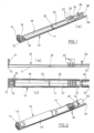
- the insert 10 including the components mounted thereon is fitted into an elongate housing sleeve 60, see Figure 3 .
- the housing sleeve 60 forms the major part of the housing of the electronic smoking device and is designed as a hollow shell having a first end 62 and second end 64.
- the housing sleeve 60 is open both at its first end 62 and at its second end 64 so that the insert 10 can be moved into the housing sleeve 60 either via the first end 62 or via the second end 64.
- the insert 10 irreversibly locks inside the housing sleeve 60, i.e. by means of protrusions or claws emerging from one of the parts engaging in related depressions provided at the other part. In this case, only one of the ends of the housing sleeve 60 might be suitable for introducing the insert 10.
- the end wall 14 By being of a shape which extends across the extent of the aperture of the housing sleeve 60 into which the insert 10 is inserted, the end wall 14 causes the insert 10 to be aligned with the cavity defined by the housing sleeve 60. This then orientates the insert 10 so that it can be slid into place.
- the end wall 14 therefore protects the electronics components mounted on the insert 10 from being struck as the insert 10 is slid into place.
- the support ring 26 potentially has a similar effect.
- the insert 10 is stabilised against lateral movement by the end wall 14 and the support ring 26, both fitting to the internal wall shape of the housing sleeve 60.
- FIG. 3 shows three windows 66 on one side of the housing sleeve 30. Another three windows are provided on the remote side. Each window 66 is associated with one of the LEDs 46. Because of the precise alignment of the insert 10 including the LEDs 46 and the housing sleeve 60, it is ensured that the light emitted from a certain LED 46 is shielded by the related walls 22 so that it can only penetrate one of the windows 66.
- the shape of the end wall 14 is that of a rounded triangle. It matches to the cross-sectional shape of the housing sleeve 60. This ensures that a particular orientation of the insert 10 is forced when it is inserted into the housing sleeve 60 and that the electronics components are aligned in a particular way, e.g. vis a vis the windows 66 or vis a vis any air ducts, etc.
- FIG. 4 illustrates the complete electronic smoking device, designated by reference numeral 70, according to the embodiment.
- the electronic smoking device 70 comprises a mouth-ended portion 72.
- the mouth-ended portion 72 includes a housing cap 74 provided with an inhalation hole at its free end (not visible in Figure 4 ) and accommodating an atomizer and a reservoir filled with a liquid to be atomised.
- Figure 5 displays all internal components of the electronic smoking device 70 in the absence of the housing sleeve 60 and the housing cap 74 for illustration purposes. Most of Figure 5 is identical to Figure 2 . Additionally, Figure 5 shows the atomizer (designated by 76) and the reservoir (designated by 78). The atomizer 76 is mounted on the connector 50 by means of a male axial connector (not shown in the Figures). This connection provides for a mechanical connection between both portions of the electronic smoking device 70, i.e. the portion defined by housing sleeve 60 and the mouth-ended portion 72. Moreover, it connects an electrical heating wire included in the atomizer 76 to the battery 40 and the control electronics provided on the circuit board 44.
- the material of the housing sleeve 60 is also ABS so that the material properties of the insert 10 and the housing sleeve 60 match to each other.
- the housing cap 74 can be removed from the housing sleeve 60 in order to get access to the reservoir 78.
- the reservoir 78 is designed as a capsule closed on one end by an aluminium film. This aluminium film is pierced by a spike extending from the atomizer 76, when the reservoir 78 is mounted on the atomizer 76. Thereafter, the housing cap 74 can be placed on the housing sleeve 60 again. When the user sucks on the housing cap 74, a vacuum inside the housing sleeve 60 is created, which is sensed by the inhaling sensor 48 that transmits a corresponding signal to the control electronics on the circuit board 44. If a puff is detected, the electric heater in the atomizer 76 is switched on.
- the liquid from the reservoir 78 is fed by a kind of metallic wick to the area of the heater so that it can be atomised, forming an aerosol.
- the aerosol leaves the atomizer area and is inhaled through the inhalation hole.
- the inhaling sensor 48 senses when the user stops sucking on the housing cap 74. In response thereto, the heater is switched off.
- the battery 40 in the embodiment a rechargeable lithium ion battery, can be charged via charging port 42.
- the status of the electronic smoking device 70 e.g., charging, standby, sucking, error
- the LEDs 46 are indicated by the LEDs 46.
- an electronic smoking device comprising an elongate housing sleeve having a first end and a second end and accommodating the following components: a battery as an electric power source adapted to power an electrically activatable atomizer including an electric heater, a puff detector adapted to detect a user requesting the generation of an aerosol, and control electronics connected to the puff detector (48) and adapted to control the heater of the atomizer.
- the electronic smoking device further comprises an elongate insert that permits fitting into the housing sleeve via one of the ends of the housing sleeve, wherein the following components are mounted on the insert: the battery, the puff detector, the control electronics, and a charging port for charging the battery, wherein the charging port is mounted at a first end of the insert.
- the insert may comprise protrusions and/or depressions adapted to immobilise the components mounted on the insert.
- the insert may comprises at least one compartment wall.
- a connector may be mounted at a second end of the insert.
- the connector may be adapted to provide a connection to another portion of the electronic smoking device, which comprises an atomizer, and wherein the connector may further include electrical connections for the atomizer.
- the insert may be designed as an elongate partial or open shell which provides a minor electronics area, a battery area, and a major electronics area.
- At least one electrical lead may be adapted to connect components mounted on the insert is incorporated in the insert.
- the insert may comprises a seal within the housing sleeve.
- the insert is adapted to define a flow resistance within the housing sleeve.
- the puff detector may comprise an inhaling sensor.
- the inhaling sensor may be adapted to detect a pressure drop inside the electronic smoking device.
- the electronic smoking device may comprise an electronic circuit board.
- the elongate insert may permit lateral access.
- the elongate insert may be manufactured in one piece.
- the first end of the insert may be located at the first end of the housing sleeve when the insert is fitted into the housing sleeve.
Landscapes
- Health & Medical Sciences (AREA)
- Engineering & Computer Science (AREA)
- Bioinformatics & Cheminformatics (AREA)
- Pulmonology (AREA)
- Anesthesiology (AREA)
- Biomedical Technology (AREA)
- Heart & Thoracic Surgery (AREA)
- Hematology (AREA)
- Life Sciences & Earth Sciences (AREA)
- Animal Behavior & Ethology (AREA)
- General Health & Medical Sciences (AREA)
- Public Health (AREA)
- Veterinary Medicine (AREA)
- Battery Mounting, Suspending (AREA)
- Details Of Connecting Devices For Male And Female Coupling (AREA)
- Catching Or Destruction (AREA)
- Charge And Discharge Circuits For Batteries Or The Like (AREA)
Claims (14)
- Elektronische Rauchvorrichtung, umfassend:eine längliche Gehäusehülse (60) mit einem ersten Ende (62) und einem zweiten Ende (64), undeinen Verdampferabschnitt (72), der zusätzlich zu der Gehäusehülse (60) vorgesehen ist, sodass ein elektrisch aktivierbarer Verdampfer (76), der einen elektrischen Erhitzer umfasst, und ein ein Liquid enthaltendes Reservoir (78) in dem Verdampferabschnitt (72) angeordnet sind und nicht in der Gehäusehülse (60) untergebracht sind,wobei die Gehäusehülse (60) einen länglichen Einsatz (10) umfasst, der dazu ausgestaltet ist, über eine Öffnung in einem der Enden (62, 64) der Gehäusehülse (60) in die Gehäusehülse (60) zu passen, wobei die folgenden Komponenten an dem Einsatz (10) angebracht sind:- eine wiederaufladbare Batterie (40) als eine elektrische Leistungsquelle, die dazu angepasst ist, den elektrisch aktivierbaren Verdampfer (76) mit Leistung zu versorgen,- ein Zugdetektor (48), der dazu angepasst ist, einen die Erzeugung eines Aerosols anfordernden Benutzer zu erkennen,- Steuerelektronik (42, 44), die mit dem Zugdetektor (48) verbunden und dazu angepasst ist, den Erhitzer des Verdampfers (76) zu steuern, wobei der Zugdetektor (48) dazu angepasst ist, einen die Erzeugung eines Aerosols anfordernden Benutzer zu erkennen, und- einen Verbinder (50), der an einem zweiten Ende (30) des Einsatzes (10) angebracht ist, das sich im Bereich des zweiten Endes (64) der Gehäusehülse (60) befindet, wenn der Einsatz in die Vorrichtung eingepasst ist, wobei der Verbinder (50) dazu angepasst ist, eine Verbindung mit dem Verdampferabschnitt (72) der elektronischen Rauchvorrichtung (70) bereitzustellen, umfassend den Verdampfer (76) und das Reservoir (78), wobei der Verbinder (50) dazu angepasst ist, eine mechanische Verbindung mit dem Verdampferabschnitt (72) der elektronischen Rauchvorrichtung (70) bereitzustellen und elektrische Anschlüsse für den Verdampfer (76) in dem Verdampferabschnitt (72) umfasst.
- Elektronische Rauchvorrichtung nach Anspruch 1, wobei die Steuerelektronik (42, 44), der Zugdetektor (48) und der Verbinder entlang der Längsachse der länglichen Gehäusehülse aufeinanderfolgend angeordnet sind.
- Elektronische Rauchvorrichtung nach Anspruch 1 oder 2, wobei der Einsatz (10)- Vorsprünge (22, 32) und/oder Vertiefungen (23) umfasst, die dazu angepasst sind, die an dem Einsatz (10) angebrachten Komponenten (40, 42, 44, 48, 50) zu immobilisieren, und/oder- wenigstens eine Fachwand (22) umfasst.
- Elektronische Rauchvorrichtung nach einem der Ansprüche 1 bis 3, wobei ein Ladeanschluss (42) zum Laden der Batterie (40) an einem ersten Ende (12) des Einsatzes (10) angebracht ist.
- Elektronische Rauchvorrichtung nach einem der Ansprüche 1 bis 3, wobei der Ladeanschluss in eine Endkappe integriert ist und die Endkappe dazu ausgestaltet ist, die Gehäusehülse (60) nach Einsetzen des Einsatzes (10) zu schließen.
- Elektronische Rauchvorrichtung nach Anspruch 5, wobei das erste Ende (12) des Einsatzes (10) im Bereich eines ersten Endes der Gehäusehülse angeordnet ist.
- Elektronische Rauchvorrichtung nach einem der Ansprüche 1 bis 6, wobei an dem Einsatz (10) LEDs angebracht sind, die sich unter jeweiligen in der Gehäusehülse (60) vorgesehenen Lichtfenstern befinden, wenn der Einsatz in die Gehäusehülse (60) eingesetzt ist.
- Elektronische Rauchvorrichtung nach Anspruch 7, wobei der Einsatz eine Fachwand oder einen Steg umfasst, der zur Abschirmung von LED-Licht vorgesehen ist.
- Elektronische Rauchvorrichtung nach einem der Ansprüche 1 bis 8, wobei der Zugdetektor einen Inhalationssensor (48) umfasst, der dazu ausgestaltet ist, einen Druckabfall im Inneren der elektronischen Rauchvorrichtung zu erkennen.
- Elektronische Rauchvorrichtung nach einem der Ansprüche 1 bis 9, wobei der Einsatz (10) eine Dichtung umfasst, wobei die Dichtung vorzugsweise- einen Strömungswiderstand innerhalb der Gehäusehülse (60) definiert, um eine Aktivierung des Drucksensors zuzulassen, oder- verschiedene Fächer innerhalb der Gehäusehülse trennt.
- Elektronische Rauchvorrichtung nach einem der Ansprüche 1 bis 10, wobei die Steuerelektronik eine elektronische Leiterplatte (44) umfasst.
- Elektronische Rauchvorrichtung nach einem der Ansprüche 1 bis 11, wobei der längliche Einsatz (10) aus einem Stück gefertigt ist.
- Verfahren zur Herstellung einer elektronischen Rauchvorrichtung, umfassend die Schritte:Bereitstellen einer länglichen Gehäusehülse (60) mit einem ersten Ende (62) und einem zweiten Ende (64),Bereitstellen eines Verdampferabschnitts (72) zusätzlich zu der Gehäusehülse (60), sodass ein elektrisch aktivierbarer Verdampfer (76), der einen elektrischen Erhitzer umfasst, und ein ein Liquid enthaltendes Reservoir (78) in dem Verdampferabschnitt (72) angeordnet sind und nicht in der Gehäusehülse (60) untergebracht sind, wobei die Gehäusehülse (60) einen länglichen Einsatz (10) umfasst, der dazu ausgestaltet ist, über eine Öffnung in einem der Enden (62, 64) der Gehäusehülse (60) in die Gehäusehülse (60) zu passen,Anbringen der folgenden Komponenten an dem Einsatz (10):- eine wiederaufladbare Batterie (40) als eine elektrische Leistungsquelle, die dazu angepasst ist, den elektrisch aktivierbaren Verdampfer (76) mit Leistung zu versorgen,- ein Zugdetektor (48), der dazu angepasst ist, einen die Erzeugung eines Aerosols anfordernden Benutzer zu erkennen, und- Steuerelektronik (42, 44), die mit dem Zugdetektor (48) verbunden und dazu angepasst ist, den Erhitzer des Verdampfers (76) zu steuern, wobei der Zugdetektor (48) dazu angepasst ist, einen die Erzeugung eines Aerosols anfordernden Benutzer zu erkennen,- einen Verbinder (50), der an einem zweiten Ende (30) des Einsatzes (10) angebracht ist, das sich im Bereich des zweiten Endes (64) der Gehäusehülse (60) befindet, wenn der Einsatz in die Vorrichtung eingepasst ist, wobei der Verbinder (50) dazu angepasst ist, eine Verbindung mit dem Verdampferabschnitt (72) der elektronischen Rauchvorrichtung (70) bereitzustellen, umfassend den Verdampfer (76) und das Reservoir (78), wobei der Verbinder (50) dazu angepasst ist, eine mechanische Verbindung mit dem Verdampferabschnitt (72) der elektronischen Rauchvorrichtung (70) bereitzustellen und elektrische Anschlüsse für den Verdampfer (76) in dem Verdampferabschnitt (72) umfasst,- Einpassen des Einsatzes (10) mit den daran angebrachten Komponenten über eine Öffnung in einem der Enden der Gehäusehülse (60) in die Gehäusehülse (60).
- Verfahren nach Anspruch 13, das die Merkmale eines der Ansprüche 2 bis 12 bereitstellt.
Priority Applications (4)
| Application Number | Priority Date | Filing Date | Title |
|---|---|---|---|
| EP23150933.2A EP4179891B1 (de) | 2013-08-06 | 2013-08-06 | Elektronische rauchvorrichtung und verfahren zur herstellung davon |
| HUE23150933A HUE071661T2 (hu) | 2013-08-06 | 2013-08-06 | Elektronikus dohányzóeszköz és annak gyártási eljárása |
| PL23150933.2T PL4179891T3 (pl) | 2013-08-06 | 2013-08-06 | Elektroniczne urządzenie do palenia i proces jego wytwarzania |
| ES23150933T ES3028582T3 (en) | 2013-08-06 | 2013-08-06 | Electronic smoking device and process of manufacturing thereof |
Applications Claiming Priority (3)
| Application Number | Priority Date | Filing Date | Title |
|---|---|---|---|
| EP13003929.0A EP2835063B2 (de) | 2013-08-06 | 2013-08-06 | Elektronische Rauchvorrichtung und Herstellungsverfahren dafür |
| EP23150933.2A EP4179891B1 (de) | 2013-08-06 | 2013-08-06 | Elektronische rauchvorrichtung und verfahren zur herstellung davon |
| EP19164600.9A EP3536179A1 (de) | 2013-08-06 | 2013-08-06 | Elektronische rauchvorrichtung und verfahren zur herstellung davon |
Related Parent Applications (3)
| Application Number | Title | Priority Date | Filing Date |
|---|---|---|---|
| EP19164600.9A Division EP3536179A1 (de) | 2013-08-06 | 2013-08-06 | Elektronische rauchvorrichtung und verfahren zur herstellung davon |
| EP13003929.0A Division EP2835063B2 (de) | 2013-08-06 | 2013-08-06 | Elektronische Rauchvorrichtung und Herstellungsverfahren dafür |
| EP13003929.0A Division-Into EP2835063B2 (de) | 2013-08-06 | 2013-08-06 | Elektronische Rauchvorrichtung und Herstellungsverfahren dafür |
Publications (2)
| Publication Number | Publication Date |
|---|---|
| EP4179891A1 EP4179891A1 (de) | 2023-05-17 |
| EP4179891B1 true EP4179891B1 (de) | 2025-04-30 |
Family
ID=48979506
Family Applications (4)
| Application Number | Title | Priority Date | Filing Date |
|---|---|---|---|
| EP19164600.9A Pending EP3536179A1 (de) | 2013-08-06 | 2013-08-06 | Elektronische rauchvorrichtung und verfahren zur herstellung davon |
| EP13003929.0A Active EP2835063B2 (de) | 2013-08-06 | 2013-08-06 | Elektronische Rauchvorrichtung und Herstellungsverfahren dafür |
| EP23150933.2A Active EP4179891B1 (de) | 2013-08-06 | 2013-08-06 | Elektronische rauchvorrichtung und verfahren zur herstellung davon |
| EP22206904.9A Active EP4166019B1 (de) | 2013-08-06 | 2013-08-06 | Elektronische rauchvorrichtung und verfahren zur herstellung davon |
Family Applications Before (2)
| Application Number | Title | Priority Date | Filing Date |
|---|---|---|---|
| EP19164600.9A Pending EP3536179A1 (de) | 2013-08-06 | 2013-08-06 | Elektronische rauchvorrichtung und verfahren zur herstellung davon |
| EP13003929.0A Active EP2835063B2 (de) | 2013-08-06 | 2013-08-06 | Elektronische Rauchvorrichtung und Herstellungsverfahren dafür |
Family Applications After (1)
| Application Number | Title | Priority Date | Filing Date |
|---|---|---|---|
| EP22206904.9A Active EP4166019B1 (de) | 2013-08-06 | 2013-08-06 | Elektronische rauchvorrichtung und verfahren zur herstellung davon |
Country Status (10)
| Country | Link |
|---|---|
| US (4) | US10492529B2 (de) |
| EP (4) | EP3536179A1 (de) |
| CN (2) | CN105658099B (de) |
| ES (3) | ES3028582T3 (de) |
| GB (1) | GB2518260B (de) |
| HK (1) | HK1201424A1 (de) |
| HU (2) | HUE071661T2 (de) |
| PL (3) | PL4179891T3 (de) |
| TW (1) | TW201515586A (de) |
| WO (1) | WO2015018479A1 (de) |
Families Citing this family (64)
| Publication number | Priority date | Publication date | Assignee | Title |
|---|---|---|---|---|
| US10244793B2 (en) | 2005-07-19 | 2019-04-02 | Juul Labs, Inc. | Devices for vaporization of a substance |
| US10130123B2 (en) | 2013-03-15 | 2018-11-20 | Juul Labs, Inc. | Vaporizer devices with blow discrimination |
| US10279934B2 (en) | 2013-03-15 | 2019-05-07 | Juul Labs, Inc. | Fillable vaporizer cartridge and method of filling |
| EP3536179A1 (de) | 2013-08-06 | 2019-09-11 | Fontem Holdings 1 B.V. | Elektronische rauchvorrichtung und verfahren zur herstellung davon |
| JP6022701B2 (ja) * | 2013-09-30 | 2016-11-09 | 日本たばこ産業株式会社 | 非燃焼型香味吸引器 |
| US10039321B2 (en) | 2013-11-12 | 2018-08-07 | Vmr Products Llc | Vaporizer |
| US10076139B2 (en) | 2013-12-23 | 2018-09-18 | Juul Labs, Inc. | Vaporizer apparatus |
| US10058129B2 (en) | 2013-12-23 | 2018-08-28 | Juul Labs, Inc. | Vaporization device systems and methods |
| US10159282B2 (en) | 2013-12-23 | 2018-12-25 | Juul Labs, Inc. | Cartridge for use with a vaporizer device |
| US20160366947A1 (en) | 2013-12-23 | 2016-12-22 | James Monsees | Vaporizer apparatus |
| KR102267997B1 (ko) | 2013-12-23 | 2021-06-23 | 쥴 랩스, 인크. | 기화 디바이스 시스템 및 방법 |
| USD842536S1 (en) | 2016-07-28 | 2019-03-05 | Juul Labs, Inc. | Vaporizer cartridge |
| USD825102S1 (en) | 2016-07-28 | 2018-08-07 | Juul Labs, Inc. | Vaporizer device with cartridge |
| PL3622839T3 (pl) | 2014-03-19 | 2024-05-06 | Philip Morris Products S.A. | Płaszczyzna monolityczna ze stykami elektrycznymi i sposoby wytwarzania |
| ES3027188T3 (en) | 2014-10-02 | 2025-06-13 | Cue Vapor Ltd | Disposable tank electronic cigarette, method of manufacture and method of use |
| CN112155255B (zh) | 2014-12-05 | 2025-10-28 | 尤尔实验室有限公司 | 校正剂量控制 |
| EP3229622B1 (de) * | 2014-12-11 | 2019-10-16 | Philip Morris Products S.a.s. | Inhaliervorrichtung mit benutzererkennung basierend auf inhalationsverhalten |
| TWI700997B (zh) * | 2015-03-25 | 2020-08-11 | 瑞士商菲利浦莫里斯製品股份有限公司 | 具有電接點之單片平面 |
| US11000069B2 (en) * | 2015-05-15 | 2021-05-11 | Rai Strategic Holdings, Inc. | Aerosol delivery device and methods of formation thereof |
| US10398169B2 (en) | 2015-06-25 | 2019-09-03 | Altria Client Services Llc | E-vapor device including at least one of a bayonet connector and a connector with a knurled pattern for forming a welded junction |
| DK3386323T3 (da) * | 2015-12-18 | 2021-04-26 | Jt Int Sa | Personlig fordampningsanordning |
| WO2017139595A1 (en) | 2016-02-11 | 2017-08-17 | Pax Labs, Inc. | Fillable vaporizer cartridge and method of filling |
| EA039727B1 (ru) | 2016-02-11 | 2022-03-04 | Джуул Лэбз, Инк. | Надежно прикрепляющиеся картриджи для испарительных устройств |
| US10405582B2 (en) | 2016-03-10 | 2019-09-10 | Pax Labs, Inc. | Vaporization device with lip sensing |
| USD849996S1 (en) | 2016-06-16 | 2019-05-28 | Pax Labs, Inc. | Vaporizer cartridge |
| USD848057S1 (en) | 2016-06-23 | 2019-05-07 | Pax Labs, Inc. | Lid for a vaporizer |
| USD836541S1 (en) | 2016-06-23 | 2018-12-25 | Pax Labs, Inc. | Charging device |
| USD851830S1 (en) | 2016-06-23 | 2019-06-18 | Pax Labs, Inc. | Combined vaporizer tamp and pick tool |
| EP3272236B1 (de) * | 2016-07-22 | 2021-06-16 | Fontem Holdings 1 B.V. | Elektronische rauchvorrichtung |
| US10034495B2 (en) | 2016-07-25 | 2018-07-31 | Fontem Holdings 1 B.V. | Device for storing and vaporizing liquid |
| US9974338B2 (en) | 2016-07-25 | 2018-05-22 | Fontem Holdings 1 B.V. | Electronic cigarette with illuminated tip |
| US10383367B2 (en) * | 2016-07-25 | 2019-08-20 | Fontem Holdings 1 B.V. | Electronic cigarette power supply portion |
| US20180042291A1 (en) * | 2016-08-11 | 2018-02-15 | Mello Labs LLC | Smoking apparatus |
| KR102327122B1 (ko) | 2016-12-12 | 2021-11-16 | 브이엠알 프로덕츠 엘엘씨 | 기화기 카트리지 |
| USD887632S1 (en) | 2017-09-14 | 2020-06-16 | Pax Labs, Inc. | Vaporizer cartridge |
| GB201717484D0 (en) | 2017-10-24 | 2017-12-06 | Nicoventures Holdings Ltd | Electronic aerosol provision device |
| GB201717480D0 (en) | 2017-10-24 | 2017-12-06 | Nicoventures Holdings Ltd | Electronic aerosol provision device with seal |
| GB201717479D0 (en) | 2017-10-24 | 2017-12-06 | Nicoventures Holdings Ltd | Hatch section for an electronic aerosol provision device |
| GB201717486D0 (en) | 2017-10-24 | 2017-12-06 | Nicoventures Holdings Ltd | Mechanism for hatch of electronic aerosol provision device |
| GB201717489D0 (en) | 2017-10-24 | 2017-12-06 | Nicoventures Holdings Ltd | Electronic aerosol provision device |
| CN108338420B (zh) * | 2018-02-09 | 2020-09-15 | 常州市派腾电子技术服务有限公司 | 发热丝识别装置、方法、电子烟及计算机存储介质 |
| EP3560362A1 (de) | 2018-04-24 | 2019-10-30 | JT International SA | Elektronische zigarette mit schutzhülle |
| US10888125B2 (en) | 2018-06-27 | 2021-01-12 | Juul Labs, Inc. | Vaporizer device with subassemblies |
| CN212574135U (zh) * | 2018-06-27 | 2021-02-23 | 尤尔实验室有限公司 | 蒸发器装置 |
| CN111096478A (zh) * | 2018-10-26 | 2020-05-05 | 日本烟草产业株式会社 | 雾化单元以及非燃烧式吸取器 |
| JP6550671B1 (ja) * | 2018-10-26 | 2019-07-31 | 日本たばこ産業株式会社 | 霧化ユニット、及び非燃焼式吸引器 |
| WO2020097341A1 (en) | 2018-11-08 | 2020-05-14 | Juul Labs, Inc. | Cartridges for vaporizer devices |
| US11156766B2 (en) | 2018-11-19 | 2021-10-26 | Rai Strategic Holdings, Inc. | Aerosol delivery device |
| GB201902220D0 (en) * | 2019-02-18 | 2019-04-03 | Nicoventures Trading Ltd | Aerosol provision systems |
| CA192725S (en) | 2019-08-01 | 2022-04-07 | Nicoventures Trading Ltd | Aerosol generating device |
| US20220248762A1 (en) * | 2019-08-08 | 2022-08-11 | Jt International S.A. | Aerosol Generation Device, Method for Manufacturing |
| PH12022551028A1 (en) * | 2019-11-04 | 2023-05-29 | Juul Labs Inc | Vaporizer device |
| WO2021089490A1 (en) | 2019-11-06 | 2021-05-14 | Jt International Sa | Electronic cigarette |
| WO2021089465A1 (en) | 2019-11-06 | 2021-05-14 | Jt International Sa | Electronic cigarette with a sensor integrated into a display unit |
| WO2021105180A1 (en) * | 2019-11-29 | 2021-06-03 | Jt International Sa | Electronic cigarette |
| IT202000004585A1 (it) * | 2020-03-04 | 2021-09-04 | Nuovo Pignone Tecnologie Srl | Turbina e pala perfezionate per la protezione della radice dai gas caldi del percorso del flusso. |
| JP6749513B1 (ja) * | 2020-03-05 | 2020-09-02 | 日本たばこ産業株式会社 | 吸引器用コントローラ |
| USD985187S1 (en) | 2021-01-08 | 2023-05-02 | Nicoventures Trading Limited | Aerosol generator |
| US11789476B2 (en) | 2021-01-18 | 2023-10-17 | Altria Client Services Llc | Heat-not-burn (HNB) aerosol-generating devices including intra-draw heater control, and methods of controlling a heater |
| US11910826B2 (en) | 2021-01-18 | 2024-02-27 | Altria Client Services Llc | Heat-not-burn (HNB) aerosol-generating devices and capsules |
| USD1095794S1 (en) | 2021-01-18 | 2025-09-30 | Altria Client Services Llc | Aerosol-generating capsule |
| USD984730S1 (en) | 2021-07-08 | 2023-04-25 | Nicoventures Trading Limited | Aerosol generator |
| US12127592B2 (en) | 2021-09-20 | 2024-10-29 | Altria Client Services Llc | Capsule validation for heat-not-burn (HNB) aerosol-generating devices |
| JPWO2023105771A1 (de) * | 2021-12-10 | 2023-06-15 |
Family Cites Families (77)
| Publication number | Priority date | Publication date | Assignee | Title |
|---|---|---|---|---|
| US251340A (en) | 1881-06-30 | 1881-12-20 | Lewis Ginter | cigarette |
| US2267966A (en) * | 1940-09-13 | 1941-12-30 | William P Allen | Cigarette holder |
| US5052413A (en) * | 1987-02-27 | 1991-10-01 | R. J. Reynolds Tobacco Company | Method for making a smoking article and components for use therein |
| US5088507A (en) * | 1987-07-17 | 1992-02-18 | R. J. Reynolds Tobacco Company | Apparatus for assembling components of a smoking article |
| USH1271H (en) | 1991-07-22 | 1994-01-04 | R. J. Reynolds Tobacco Co. | Cigarette |
| DE69719719T2 (de) * | 1996-06-17 | 2004-03-25 | Japan Tobacco Inc. | Aromaerzeugende artikel und aromaerzeugendes gerät |
| US7527059B2 (en) * | 2002-07-02 | 2009-05-05 | Iannuzzi Diane M | Aromatic cigarette substitute |
| ATE470468T1 (de) | 2003-08-04 | 2010-06-15 | Alexza Pharmaceuticals Inc | Substrate für eine medikamentenverabreichungsvorrichtung und verfahren zur bereitung |
| US7540286B2 (en) | 2004-06-03 | 2009-06-02 | Alexza Pharmaceuticals, Inc. | Multiple dose condensation aerosol devices and methods of forming condensation aerosols |
| CA2854037C (en) | 2004-06-03 | 2020-06-23 | Alexza Pharmaceuticals, Inc. | Multiple dose condensation aerosol devices and uses thereof |
| USD532927S1 (en) | 2006-01-26 | 2006-11-28 | Jonathan Drew, Inc. | Elongated cigar |
| US7726320B2 (en) * | 2006-10-18 | 2010-06-01 | R. J. Reynolds Tobacco Company | Tobacco-containing smoking article |
| US20080257367A1 (en) | 2007-04-23 | 2008-10-23 | Greg Paterno | Electronic evaporable substance delivery device and method |
| EP1989946A1 (de) * | 2007-05-11 | 2008-11-12 | Rauchless Inc. | Rauchartikel, Ladevorrichtung und Verwendungsverfahren |
| CN201051862Y (zh) | 2007-06-08 | 2008-04-30 | 西安天健医药科学研究所 | 一种仿真烟 |
| CN201199922Y (zh) | 2007-07-16 | 2009-03-04 | 李德红 | 电子烟及其感应开关 |
| US9155848B2 (en) * | 2007-10-15 | 2015-10-13 | Vapir, Inc. | Method and system for vaporization of a substance |
| ES2527936T3 (es) | 2008-06-27 | 2015-02-02 | Fontem Holdings 2 B.V. | Un substitutivo electrónico de cigarrillo |
| DE102008045048A1 (de) * | 2008-08-27 | 2010-03-04 | Hauni Maschinenbau Ag | Messkörper zum Erkennen von Störquellen innerhalb eines Leitungssystems für Tabak verarbeitende Produkte |
| AT507187B1 (de) | 2008-10-23 | 2010-03-15 | Helmut Dr Buchberger | Inhalator |
| CN101518361B (zh) * | 2009-03-24 | 2010-10-06 | 北京格林世界科技发展有限公司 | 高仿真电子烟 |
| CN201379073Y (zh) | 2009-03-30 | 2010-01-13 | 北京格林世界科技发展有限公司 | 高仿真电子香烟的结构 |
| CN201491720U (zh) | 2009-06-05 | 2010-06-02 | 黄德 | 一次性电子烟 |
| CN101606758B (zh) * | 2009-07-14 | 2011-04-13 | 方晓林 | 电子烟 |
| US8897628B2 (en) * | 2009-07-27 | 2014-11-25 | Gregory D. Conley | Electronic vaporizer |
| CN201528661U (zh) * | 2009-09-30 | 2010-07-21 | 吴宗文 | 电子烟盒 |
| CN201750712U (zh) * | 2010-04-02 | 2011-02-23 | 陈志平 | 电子雾化吸入器的吸嘴 |
| CN101843368A (zh) * | 2010-04-02 | 2010-09-29 | 陈志平 | 电子雾化吸入器的吸嘴 |
| US8550068B2 (en) * | 2010-05-15 | 2013-10-08 | Nathan Andrew Terry | Atomizer-vaporizer for a personal vaporizing inhaler |
| US9861772B2 (en) | 2010-05-15 | 2018-01-09 | Rai Strategic Holdings, Inc. | Personal vaporizing inhaler cartridge |
| CN201830899U (zh) | 2010-06-09 | 2011-05-18 | 李永海 | 电子香烟的供电装置 |
| CN102160906B (zh) * | 2010-11-01 | 2012-08-08 | 常州市富艾发进出口有限公司 | 口吸式便携雾化器 |
| CN202112305U (zh) * | 2011-01-27 | 2012-01-18 | 文昌 | 具储存装置的多功能吸入式电子烟雾产生器 |
| US20120199146A1 (en) * | 2011-02-09 | 2012-08-09 | Bill Marangos | Electronic cigarette |
| AT510837B1 (de) | 2011-07-27 | 2012-07-15 | Helmut Dr Buchberger | Inhalatorkomponente |
| US9399110B2 (en) * | 2011-03-09 | 2016-07-26 | Chong Corporation | Medicant delivery system |
| WO2012120487A2 (en) | 2011-03-09 | 2012-09-13 | Chong Corporation | Medicant delivery system |
| US8528569B1 (en) * | 2011-06-28 | 2013-09-10 | Kyle D. Newton | Electronic cigarette with liquid reservoir |
| US20140360517A1 (en) * | 2011-08-11 | 2014-12-11 | Wisplite Technologies Inc. | Portable electronic vapor-producing device and method |
| HK1197203A1 (en) * | 2011-08-16 | 2015-01-09 | Pax Labs, Inc. | Low temperature electronic vaporization device and methods |
| RU2614615C2 (ru) * | 2011-09-06 | 2017-03-28 | Бритиш Америкэн Тобэкко (Инвестментс) Лимитед | Нагревание курительного материала |
| HUE045286T2 (hu) * | 2011-09-28 | 2019-12-30 | Philip Morris Products Sa | Permeábilis elektromos hõálló fólia folyadékok elpárologtatására egy párologtatómembránnal rendelkezõ, egyszer használatos szopókákból |
| CN102499488B (zh) | 2011-09-28 | 2014-03-12 | 卓尔悦(常州)电子科技有限公司 | 电子烟 |
| CN202385728U (zh) | 2011-11-25 | 2012-08-22 | 周学武 | 内置雾化器电子香烟 |
| USD675777S1 (en) | 2011-12-16 | 2013-02-05 | Shenzhen Jieshibo Technology Co., Ltd. | Electronic cigarette |
| AR089602A1 (es) * | 2011-12-30 | 2014-09-03 | Philip Morris Products Sa | Articulo generador de aerosoles para usar con un dispositivo generador de aerosoles |
| KR20140117398A (ko) * | 2012-01-03 | 2014-10-07 | 필립모리스 프로덕츠 에스.에이. | 비롤링 에어로졸 발생 장치 및 시스템 |
| PL2800485T3 (pl) * | 2012-01-03 | 2017-01-31 | Philip Morris Products Sa | Wieloboczne urządzenie do wytwarzania aerozolu oraz układ |
| MX347697B (es) * | 2012-01-03 | 2017-05-09 | Philip Morris Products Sa | Dispositivo y sistema de generación de aerosol. |
| CN202445137U (zh) | 2012-03-12 | 2012-09-26 | 刘团芳 | 可卸油瓶手持式电子烟 |
| CN202456412U (zh) | 2012-03-12 | 2012-10-03 | 刘团芳 | 可卸油瓶便携式电子烟 |
| WO2013138384A2 (en) | 2012-03-12 | 2013-09-19 | Uptoke Llc | Electronic vaporizing device and methods for use |
| CN202618275U (zh) * | 2012-04-01 | 2012-12-26 | 惠州市吉瑞科技有限公司 | 电子烟及其吸嘴 |
| CN203776159U (zh) * | 2012-06-16 | 2014-08-20 | 惠州市吉瑞科技有限公司 | 电子烟及其电子烟装置 |
| RU122000U1 (ru) | 2012-07-18 | 2012-11-20 | Общество с ограниченной ответственностью "САМАРИН" | Электронная сигарета с изменяемым вкусом |
| CN202722502U (zh) | 2012-07-31 | 2013-02-13 | 龙功运 | 蒸发式电子香烟 |
| US8910639B2 (en) * | 2012-09-05 | 2014-12-16 | R. J. Reynolds Tobacco Company | Single-use connector and cartridge for a smoking article and related method |
| WO2014043887A1 (zh) | 2012-09-21 | 2014-03-27 | Liu Qiuming | 电子烟盒及电子烟装置 |
| GB2507104A (en) * | 2012-10-19 | 2014-04-23 | Nicoventures Holdings Ltd | Electronic inhalation device |
| US10058122B2 (en) | 2012-10-25 | 2018-08-28 | Matthew Steingraber | Electronic cigarette |
| CN202941411U (zh) | 2012-10-26 | 2013-05-22 | 江门市易龙实业有限公司 | 一种智能电子烟设备 |
| CN202958805U (zh) | 2012-12-14 | 2013-06-05 | 卓尔悦(常州)电子科技有限公司 | 一种具有可拆卸智能装置的电子烟 |
| US20140174458A1 (en) * | 2012-12-21 | 2014-06-26 | Samuel Aaron Katz | Self-contained electronic smoking device that produces smoke and ash by incineration |
| US20140182612A1 (en) * | 2012-12-28 | 2014-07-03 | Shenzhen Smoore Technology Limited | Electronic atomizing inhalation device |
| CN203152482U (zh) * | 2013-01-17 | 2013-08-28 | 刘秋明 | 电子烟 |
| US20160113325A1 (en) * | 2013-03-04 | 2016-04-28 | Kimree Hi-Tech Inc | Electronic cigarette |
| US9491974B2 (en) * | 2013-03-15 | 2016-11-15 | Rai Strategic Holdings, Inc. | Heating elements formed from a sheet of a material and inputs and methods for the production of atomizers |
| WO2014169466A1 (zh) * | 2013-04-18 | 2014-10-23 | 吉瑞高新科技股份有限公司 | 一次性电子烟 |
| WO2015010292A1 (zh) | 2013-07-24 | 2015-01-29 | 吉瑞高新科技股份有限公司 | 电子烟 |
| CN203353689U (zh) * | 2013-07-24 | 2013-12-25 | 刘秋明 | 电子烟 |
| USD721202S1 (en) | 2013-07-25 | 2015-01-13 | Kimree Hi-Tech Inc | Electronic cigarette |
| EP3536179A1 (de) | 2013-08-06 | 2019-09-11 | Fontem Holdings 1 B.V. | Elektronische rauchvorrichtung und verfahren zur herstellung davon |
| CN203415645U (zh) * | 2013-08-16 | 2014-01-29 | 刘秋明 | 电池组件及电子烟 |
| USD720882S1 (en) | 2013-12-04 | 2015-01-06 | Full Circle Enterprises, Llc | Atomizer |
| US9801505B2 (en) * | 2013-12-20 | 2017-10-31 | Toaster Labs, Inc. | Automatic fluid dispenser |
| US20150257451A1 (en) * | 2014-03-13 | 2015-09-17 | Terry Brannon | Vapor device with switch assembly |
| PL3622839T3 (pl) * | 2014-03-19 | 2024-05-06 | Philip Morris Products S.A. | Płaszczyzna monolityczna ze stykami elektrycznymi i sposoby wytwarzania |
-
2013
- 2013-08-06 EP EP19164600.9A patent/EP3536179A1/de active Pending
- 2013-08-06 HU HUE23150933A patent/HUE071661T2/hu unknown
- 2013-08-06 EP EP13003929.0A patent/EP2835063B2/de active Active
- 2013-08-06 HU HUE22206904A patent/HUE071129T2/hu unknown
- 2013-08-06 PL PL23150933.2T patent/PL4179891T3/pl unknown
- 2013-08-06 ES ES23150933T patent/ES3028582T3/es active Active
- 2013-08-06 ES ES13003929T patent/ES2744489T3/es active Active
- 2013-08-06 ES ES22206904T patent/ES3030535T3/es active Active
- 2013-08-06 EP EP23150933.2A patent/EP4179891B1/de active Active
- 2013-08-06 EP EP22206904.9A patent/EP4166019B1/de active Active
- 2013-08-06 PL PL13003929T patent/PL2835063T3/pl unknown
- 2013-08-06 PL PL22206904.9T patent/PL4166019T3/pl unknown
-
2014
- 2014-06-09 GB GB1410210.7A patent/GB2518260B/en not_active Expired - Fee Related
- 2014-07-15 CN CN201480054763.2A patent/CN105658099B/zh active Active
- 2014-07-15 US US14/910,618 patent/US10492529B2/en active Active
- 2014-07-15 CN CN202010060125.9A patent/CN111109679A/zh active Pending
- 2014-07-15 WO PCT/EP2014/001936 patent/WO2015018479A1/en not_active Ceased
- 2014-07-25 TW TW103125539A patent/TW201515586A/zh unknown
-
2015
- 2015-02-27 HK HK15101967.0A patent/HK1201424A1/en unknown
-
2019
- 2019-10-28 US US16/666,052 patent/US11202471B2/en active Active
-
2020
- 2020-12-08 US US17/115,601 patent/US11553736B2/en active Active
-
2022
- 2022-12-21 US US18/069,483 patent/US12349736B2/en active Active
Also Published As
| Publication number | Publication date |
|---|---|
| CN105658099A (zh) | 2016-06-08 |
| GB2518260B (en) | 2016-05-11 |
| US20160192705A1 (en) | 2016-07-07 |
| EP4179891A1 (de) | 2023-05-17 |
| US11553736B2 (en) | 2023-01-17 |
| EP2835063B2 (de) | 2025-11-19 |
| TW201515586A (zh) | 2015-05-01 |
| US10492529B2 (en) | 2019-12-03 |
| EP4166019B1 (de) | 2025-03-19 |
| CN105658099B (zh) | 2020-02-18 |
| PL2835063T3 (pl) | 2019-09-30 |
| US20200060350A1 (en) | 2020-02-27 |
| EP3536179A1 (de) | 2019-09-11 |
| PL4166019T3 (pl) | 2025-07-21 |
| EP4166019A1 (de) | 2023-04-19 |
| HUE071661T2 (hu) | 2025-09-28 |
| US11202471B2 (en) | 2021-12-21 |
| HK1201424A1 (en) | 2015-09-04 |
| US12349736B2 (en) | 2025-07-08 |
| CN111109679A (zh) | 2020-05-08 |
| US20230119000A1 (en) | 2023-04-20 |
| ES3028582T3 (en) | 2025-06-19 |
| ES2744489T3 (es) | 2020-02-25 |
| HUE071129T2 (hu) | 2025-08-28 |
| GB2518260A (en) | 2015-03-18 |
| ES3030535T3 (en) | 2025-06-30 |
| EP2835063B1 (de) | 2019-04-10 |
| GB201410210D0 (en) | 2014-07-23 |
| PL4179891T3 (pl) | 2025-09-01 |
| EP2835063A1 (de) | 2015-02-11 |
| WO2015018479A1 (en) | 2015-02-12 |
| US20210084988A1 (en) | 2021-03-25 |
Similar Documents
| Publication | Publication Date | Title |
|---|---|---|
| US12349736B2 (en) | Electronic smoking device | |
| US11006675B2 (en) | Vapor provision system and cartridge therefor | |
| US20140014124A1 (en) | Tip charging electronic cigarette and system and method for charging the same | |
| HK1246607A1 (en) | Vapour provision system and cartridge therefor | |
| KR20230016714A (ko) | 전자 에어로졸 제공 디바이스를 위한 해치 섹션 | |
| US20240398040A1 (en) | Aerosol delivery device/system | |
| EP4151101B1 (de) | Aerosolabgabevorrichtung/-system | |
| KR20120008252U (ko) | 흡입 장치용 기화 부재 및 상기 흡입 장치용 기화 부재를 포함하는 흡입 장치 | |
| CN113925229A (zh) | 雾化器及气溶胶发生装置 | |
| EP3838033A1 (de) | Aerosolabgabevorrichtung/-system | |
| CN119302451A (zh) | 雾化器、电子雾化装置及其成型方法 | |
| HK40009356A (en) | Vapour provision system and cartridge therefor |
Legal Events
| Date | Code | Title | Description |
|---|---|---|---|
| PUAI | Public reference made under article 153(3) epc to a published international application that has entered the european phase |
Free format text: ORIGINAL CODE: 0009012 |
|
| STAA | Information on the status of an ep patent application or granted ep patent |
Free format text: STATUS: THE APPLICATION HAS BEEN PUBLISHED |
|
| AC | Divisional application: reference to earlier application |
Ref document number: 2835063 Country of ref document: EP Kind code of ref document: P Ref document number: 3536179 Country of ref document: EP Kind code of ref document: P |
|
| AK | Designated contracting states |
Kind code of ref document: A1 Designated state(s): AL AT BE BG CH CY CZ DE DK EE ES FI FR GB GR HR HU IE IS IT LI LT LU LV MC MK MT NL NO PL PT RO RS SE SI SK SM TR |
|
| STAA | Information on the status of an ep patent application or granted ep patent |
Free format text: STATUS: REQUEST FOR EXAMINATION WAS MADE |
|
| 17P | Request for examination filed |
Effective date: 20230607 |
|
| RBV | Designated contracting states (corrected) |
Designated state(s): AL AT BE BG CH CY CZ DE DK EE ES FI FR GB GR HR HU IE IS IT LI LT LU LV MC MK MT NL NO PL PT RO RS SE SI SK SM TR |
|
| GRAP | Despatch of communication of intention to grant a patent |
Free format text: ORIGINAL CODE: EPIDOSNIGR1 |
|
| STAA | Information on the status of an ep patent application or granted ep patent |
Free format text: STATUS: GRANT OF PATENT IS INTENDED |
|
| RIC1 | Information provided on ipc code assigned before grant |
Ipc: A24F 40/10 20200101ALN20241127BHEP Ipc: A24F 40/70 20200101ALI20241127BHEP Ipc: A24F 40/40 20200101AFI20241127BHEP |
|
| INTG | Intention to grant announced |
Effective date: 20241209 |
|
| GRAS | Grant fee paid |
Free format text: ORIGINAL CODE: EPIDOSNIGR3 |
|
| GRAA | (expected) grant |
Free format text: ORIGINAL CODE: 0009210 |
|
| STAA | Information on the status of an ep patent application or granted ep patent |
Free format text: STATUS: THE PATENT HAS BEEN GRANTED |
|
| AC | Divisional application: reference to earlier application |
Ref document number: 2835063 Country of ref document: EP Kind code of ref document: P Ref document number: 3536179 Country of ref document: EP Kind code of ref document: P |
|
| AK | Designated contracting states |
Kind code of ref document: B1 Designated state(s): AL AT BE BG CH CY CZ DE DK EE ES FI FR GB GR HR HU IE IS IT LI LT LU LV MC MK MT NL NO PL PT RO RS SE SI SK SM TR |
|
| REG | Reference to a national code |
Ref country code: CH Ref legal event code: EP Ref country code: GB Ref legal event code: FG4D |
|
| P01 | Opt-out of the competence of the unified patent court (upc) registered |
Free format text: CASE NUMBER: APP_16425/2025 Effective date: 20250404 |
|
| REG | Reference to a national code |
Ref country code: DE Ref legal event code: R096 Ref document number: 602013086737 Country of ref document: DE |
|
| REG | Reference to a national code |
Ref country code: IE Ref legal event code: FG4D |
|
| REG | Reference to a national code |
Ref country code: NL Ref legal event code: FP |
|
| REG | Reference to a national code |
Ref country code: ES Ref legal event code: FG2A Ref document number: 3028582 Country of ref document: ES Kind code of ref document: T3 Effective date: 20250619 |
|
| PGFP | Annual fee paid to national office [announced via postgrant information from national office to epo] |
Ref country code: NL Payment date: 20250723 Year of fee payment: 13 |
|
| REG | Reference to a national code |
Ref country code: GR Ref legal event code: EP Ref document number: 20250401219 Country of ref document: GR Effective date: 20250707 |
|
| REG | Reference to a national code |
Ref country code: AT Ref legal event code: MK05 Ref document number: 1789174 Country of ref document: AT Kind code of ref document: T Effective date: 20250430 |
|
| PGFP | Annual fee paid to national office [announced via postgrant information from national office to epo] |
Ref country code: HU Payment date: 20250815 Year of fee payment: 13 |
|
| REG | Reference to a national code |
Ref country code: HU Ref legal event code: AG4A Ref document number: E071661 Country of ref document: HU |
|
| PG25 | Lapsed in a contracting state [announced via postgrant information from national office to epo] |
Ref country code: PT Free format text: LAPSE BECAUSE OF FAILURE TO SUBMIT A TRANSLATION OF THE DESCRIPTION OR TO PAY THE FEE WITHIN THE PRESCRIBED TIME-LIMIT Effective date: 20250901 Ref country code: FI Free format text: LAPSE BECAUSE OF FAILURE TO SUBMIT A TRANSLATION OF THE DESCRIPTION OR TO PAY THE FEE WITHIN THE PRESCRIBED TIME-LIMIT Effective date: 20250430 |
|
| PGFP | Annual fee paid to national office [announced via postgrant information from national office to epo] |
Ref country code: ES Payment date: 20250901 Year of fee payment: 13 |
|
| PGFP | Annual fee paid to national office [announced via postgrant information from national office to epo] |
Ref country code: DE Payment date: 20250724 Year of fee payment: 13 |
|
| REG | Reference to a national code |
Ref country code: LT Ref legal event code: MG9D |
|
| PG25 | Lapsed in a contracting state [announced via postgrant information from national office to epo] |
Ref country code: NO Free format text: LAPSE BECAUSE OF FAILURE TO SUBMIT A TRANSLATION OF THE DESCRIPTION OR TO PAY THE FEE WITHIN THE PRESCRIBED TIME-LIMIT Effective date: 20250730 |
|
| PGFP | Annual fee paid to national office [announced via postgrant information from national office to epo] |
Ref country code: GR Payment date: 20250725 Year of fee payment: 13 |
|
| PGFP | Annual fee paid to national office [announced via postgrant information from national office to epo] |
Ref country code: PL Payment date: 20250725 Year of fee payment: 13 Ref country code: IT Payment date: 20250723 Year of fee payment: 13 |
|
| PG25 | Lapsed in a contracting state [announced via postgrant information from national office to epo] |
Ref country code: BG Free format text: LAPSE BECAUSE OF FAILURE TO SUBMIT A TRANSLATION OF THE DESCRIPTION OR TO PAY THE FEE WITHIN THE PRESCRIBED TIME-LIMIT Effective date: 20250430 |
|
| PGFP | Annual fee paid to national office [announced via postgrant information from national office to epo] |
Ref country code: GB Payment date: 20250724 Year of fee payment: 13 |
|
| PG25 | Lapsed in a contracting state [announced via postgrant information from national office to epo] |
Ref country code: HR Free format text: LAPSE BECAUSE OF FAILURE TO SUBMIT A TRANSLATION OF THE DESCRIPTION OR TO PAY THE FEE WITHIN THE PRESCRIBED TIME-LIMIT Effective date: 20250430 |
|
| PG25 | Lapsed in a contracting state [announced via postgrant information from national office to epo] |
Ref country code: AT Free format text: LAPSE BECAUSE OF FAILURE TO SUBMIT A TRANSLATION OF THE DESCRIPTION OR TO PAY THE FEE WITHIN THE PRESCRIBED TIME-LIMIT Effective date: 20250430 |
|
| PGFP | Annual fee paid to national office [announced via postgrant information from national office to epo] |
Ref country code: FR Payment date: 20250725 Year of fee payment: 13 |
|
| PGFP | Annual fee paid to national office [announced via postgrant information from national office to epo] |
Ref country code: CH Payment date: 20250901 Year of fee payment: 13 |
|
| PG25 | Lapsed in a contracting state [announced via postgrant information from national office to epo] |
Ref country code: RS Free format text: LAPSE BECAUSE OF FAILURE TO SUBMIT A TRANSLATION OF THE DESCRIPTION OR TO PAY THE FEE WITHIN THE PRESCRIBED TIME-LIMIT Effective date: 20250731 |
|
| PGFP | Annual fee paid to national office [announced via postgrant information from national office to epo] |
Ref country code: CZ Payment date: 20250725 Year of fee payment: 13 |
|
| PGFP | Annual fee paid to national office [announced via postgrant information from national office to epo] |
Ref country code: RO Payment date: 20250804 Year of fee payment: 13 |
|
| PG25 | Lapsed in a contracting state [announced via postgrant information from national office to epo] |
Ref country code: IS Free format text: LAPSE BECAUSE OF FAILURE TO SUBMIT A TRANSLATION OF THE DESCRIPTION OR TO PAY THE FEE WITHIN THE PRESCRIBED TIME-LIMIT Effective date: 20250830 |
|
| PG25 | Lapsed in a contracting state [announced via postgrant information from national office to epo] |
Ref country code: LV Free format text: LAPSE BECAUSE OF FAILURE TO SUBMIT A TRANSLATION OF THE DESCRIPTION OR TO PAY THE FEE WITHIN THE PRESCRIBED TIME-LIMIT Effective date: 20250430 |