EP4178741B1 - Nietsetzvorrichtung - Google Patents
Nietsetzvorrichtung Download PDFInfo
- Publication number
- EP4178741B1 EP4178741B1 EP20750172.7A EP20750172A EP4178741B1 EP 4178741 B1 EP4178741 B1 EP 4178741B1 EP 20750172 A EP20750172 A EP 20750172A EP 4178741 B1 EP4178741 B1 EP 4178741B1
- Authority
- EP
- European Patent Office
- Prior art keywords
- rivet
- spindle
- module
- translation
- piston
- Prior art date
- Legal status (The legal status is an assumption and is not a legal conclusion. Google has not performed a legal analysis and makes no representation as to the accuracy of the status listed.)
- Active
Links
Images
















Classifications
-
- B—PERFORMING OPERATIONS; TRANSPORTING
- B21—MECHANICAL METAL-WORKING WITHOUT ESSENTIALLY REMOVING MATERIAL; PUNCHING METAL
- B21J—FORGING; HAMMERING; PRESSING METAL; RIVETING; FORGE FURNACES
- B21J15/00—Riveting
- B21J15/10—Riveting machines
- B21J15/30—Particular elements, e.g. supports; Suspension equipment specially adapted for portable riveters
- B21J15/32—Devices for inserting or holding rivets in position with or without feeding arrangements
-
- B—PERFORMING OPERATIONS; TRANSPORTING
- B23—MACHINE TOOLS; METAL-WORKING NOT OTHERWISE PROVIDED FOR
- B23P—METAL-WORKING NOT OTHERWISE PROVIDED FOR; COMBINED OPERATIONS; UNIVERSAL MACHINE TOOLS
- B23P19/00—Machines for simply fitting together or separating metal parts or objects, or metal and non-metal parts, whether or not involving some deformation; Tools or devices therefor so far as not provided for in other classes
- B23P19/001—Article feeders for assembling machines
-
- B—PERFORMING OPERATIONS; TRANSPORTING
- B25—HAND TOOLS; PORTABLE POWER-DRIVEN TOOLS; MANIPULATORS
- B25B—TOOLS OR BENCH DEVICES NOT OTHERWISE PROVIDED FOR, FOR FASTENING, CONNECTING, DISENGAGING, OR HOLDING
- B25B23/00—Details of, or accessories for, spanners, wrenches, screwdrivers
- B25B23/02—Arrangements for handling screws or nuts
- B25B23/04—Arrangements for handling screws or nuts for feeding screws or nuts
-
- B—PERFORMING OPERATIONS; TRANSPORTING
- B23—MACHINE TOOLS; METAL-WORKING NOT OTHERWISE PROVIDED FOR
- B23P—METAL-WORKING NOT OTHERWISE PROVIDED FOR; COMBINED OPERATIONS; UNIVERSAL MACHINE TOOLS
- B23P2700/00—Indexing scheme relating to the articles being treated, e.g. manufactured, repaired, assembled, connected or other operations covered in the subgroups
- B23P2700/01—Aircraft parts
Definitions
- the field of the invention is that of the design and production of devices implemented in industry to carry out the installation of rivets prior to their final crimping, and more particularly the evacuation of a rivet from a rivet support module.
- the patent document US-A-3 111 869 describes a rivet setting device comprising rivet storage means 183, means for dispensing rivets 178 one by one into a receptacle 211 in a rivet loading area.
- a punch 32 is first lowered to make a hole and countersink before setting a rivet. Then the receptacle containing a rivet is moved to the setting area and the punch 32 lowered again to place the rivet in the previously made hole.
- an objective of the invention is to provide a rivet setting device which can make it possible to optimize rivet setting.
- the invention aims, according to at least one embodiment, to provide such a device which is compact and/or lightweight, and which consequently allows tasks to be carried out in confined spaces.
- Another objective of the invention is, according to at least one embodiment, to provide such a device which is simple in design.
- Another objective of the invention is, according to at least one embodiment, to provide such a device which is simple to maintain.
- Another objective of the invention is to provide, in at least one embodiment, such a device that is relatively cheap.
- the invention provides a device for placing a rivet in an orifice provided in a structure to be worked according to claim 1.
- This implementation automates both the feeding and the riveting using the same device.
- the invention thus provides a compact and optimized system.
- said evacuation means are movable on two successive strokes of partial pre-insertion then total final insertion of the rivet into said orifice during which the end of the rivet then the body of the rivet are successively inserted into said orifice.
- said evacuation means comprise a telescopic pin, mounted to move in translation along the axis of said module, comprising an end intended to come into contact with a rivet placed in said module, said device comprising means for driving said pin in translation.
- a telescopic spindle allows for a compact system and integration into a multi-tasking system.
- said external pin comprises an end capable of acting on said piston when said external pin is translated towards a deployed position, and said internal pin occupies its retracted position in said external pin, to move said piston into its deployed position so as to partially insert said rivet secured to the module located at the workstation into said orifice.
- said housing provided in said internal pin is a circumferential groove, and said locking ring is movable in translation along an axis essentially orthogonal to that of said internal pin.
- a device comprises elastic return means tending to bring said connecting means back into said locking position, and unlocking means making it possible to place said connecting means in their unlocking position.
- said unlocking means comprise an unlocking ring provided with a frustoconical bore widening towards the module placed at the workstation, said unlocking ring being linked in rotation with said external pin, said locking ring being housed in said unlocking ring when said external pin is in its retracted position, the walls of the frustoconical bore acting on said locking ring to place it in its unlocking position.
- a device comprises means for driving said external pin in translation between its deployed and retracted positions and means for moving said internal pin in translation inside said external pin between its retracted and deployed positions.
- said means for driving said external spindle in translation comprise a threaded ring cooperating with a threaded portion of said main spindle and a translation motor capable of driving said threaded ring in rotation to induce a translation of said main spindle.
- said means for driving said internal spindle in translation comprise a pneumatic cylinder.
- the invention also relates to a method for installing a rivet, said method comprising a step of partial pre-insertion then a step of total final insertion of the rivet into said orifice during which the end of the rivet then the body of the rivet are successively inserted into said orifice.
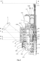
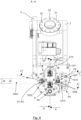
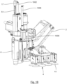
- such a multi-tasking device 1 comprises a frame 2.
- This frame 2 is equipped with means 3 for securing to a motorized handling device (not shown) to which it is intended to be secured so as to be able to be moved relative to a structure to be worked on (not shown).
- a motorized handling device not shown
- the securing means will include, for example, bolts, collars or other securing means to a cradle fitted with rollers capable of being guided in the rails of the digital grid.
- the device comprises means 4 for securing to a structure to be worked.
- suction cups 41 secured to the frame 2 capable of being connected to vacuum means such as for example a vacuum pump to improve the bonding to the surface of the structure to be worked.
- the suction cups can be attached in groups to supports, thus forming suction pads.
- Two suction pads are shown in the figures 1 , 17 And 18 , however, this number could be greater than two.
- the suction cups can be offset to one side of pin 51 (which will be described in detail later) as shown in figure 18 or distributed around pin 51 (cf. Figure 17 ).
- They may alternatively include a clamping C otherwise known in the state of the art such as for example that illustrated in figure 19 .
- the means of securing to a structure to be worked can be permanently secured to the frame. Alternatively, they can be secured to the frame via universal reversible fixing means 100.
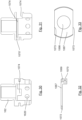
- the universal reversible fastening means 100 comprise a fastening plate 101.
- the fixing plate 101 will be secured to a supporting structure carrying the suction cups.
- the fixing plate 101 will be integral with the distal end of a bar 420 of the clamping C.
- This fixing plate 101 has an essentially rectangular section in one plane and a section with two lateral grooves 102 in another plane orthogonal to the first.
- These lateral grooves 102 extend along the entire length of the fixing plate 101 and comprise an inclined face 103 so that the thickness of the grooved portions of the fixing plate 101 tends to thicken from the ends of the plate towards the inside thereof.
- the universal reversible fixing means comprise a pair of jaws 104 of complementary shape to the grooved ends of the fixing plate 101.
- These jaws 104 therefore each define a housing 105 capable of receiving the corresponding grooved end of the fixing plate 101.
- These housings 105 thus each have two opposite surfaces, one of which is inclined relative to the other by an angle substantially identical to the angle of inclination of the corresponding groove of the fixing plate.
- Each jaw is secured to the cylinder 106 of a jack 109 whose rod 107 of the piston 108 passes through the jaw 104 and is secured to the frame.
- the jacks 109 are actuated to place the jaws 104 in their detaching position.
- the fixing plate 101 of the securing means is then inserted between the jaws 104.
- the jacks 109 are then actuated to place the jaws 105 in their securing position in which they grip the grooved ends of the plate. fixing 101.
- the device is likely to include a plurality of functional modules which will be described in more detail later.
- Each of these functional modules allows a specific task to be carried out, such as a drilling and/or countersinking operation, a rivet installation operation, a temporary fixing installation operation (e.g. a staple), or an operation of removing (or coating) a bead of sealing mastic onto a fixing element (a rivet or a screw).
- a drilling and/or countersinking operation e.g. a rivet installation operation
- a temporary fixing installation operation e.g. a staple
- an operation of removing (or coating) a bead of sealing mastic onto a fixing element a rivet or a screw.
- Other functions could be envisaged, such as screwing.
- Functional module 9 shown in alignment with pin 51 at the Figure 2 is a drilling module.
- the drilling module includes a 90 sheath.
- This 90 sheath has a tubular shape and a generally annular section.
- the sheath 90 comprises a lateral finger 900 forming a projection on its lateral wall.
- the sheath 90 comprises a lateral groove 901 which is arranged in a diametrically opposite manner and offset along the longitudinal axis of the sheath relative to the finger 900.
- This drilling module comprises an output shaft 91 (i.e. moving member) at the end of which a cutting tool such as a drill 92 (possibly stepped to allow a countersink to be made) can be secured by fixing means 93 known per se.
- the cutting tool could for example be a simple drill for making simple holes, a stepped drill, a countersink drill for making countersunk holes, a milling tool for making the countersinking of holes previously made.
- the output shaft 91 is mounted to rotate in a bearing 94 itself mounted to slide along the sleeve 90 by means of a bearing 95.
- the finger 900 of the sheath 90 of the drilling module houses a chamber 902 in which a piston 903 of a jack 904 is slidably mounted.
- the end 905 of the piston 903 is capable of being housed in a complementary shaped housing 950 provided for this purpose in the bearing 95.
- the finger 900 is extended by a supply line 906 of the cylinder 904 capable of being put into communication with a pressurized air intake pipe 907 provided in the device, with which it is in communication when it is at the work station of the device.
- Elastic return means tend to bring the piston 903 back into a position in which its end 905 is housed in the corresponding housing 950 of the bearing 95 so as to block the latter in translation inside the sheath 90 and to consequently prevent the bearing 95, the bearing 94, the output shaft 91 and the tool 92 which it carries from coming out of the sheath 90 as long as the functional module is not fitted to the spindle 51.
- the end 905 and the corresponding jack 904 constitute means for locking in translation a functional assembly of a functional module inside its sheath.
- a functional assembly comprises all the components of a functional module mounted free in translation in its sheath.
- the elastic return means may be implemented so that the end 905 projects inside the sheath 90 to form a stop for the pad 95 preventing the functional assembly from sliding inside the sheath beyond its position illustrated in FIG. Figure 5 Or 6 .
- the sheath houses at each of its ends a stop segment (not shown) each forming a stop for the functional assembly.
- a functional assembly of drilling module can slide inside the sheath between these stop segments as long as the end 905 does not protrude into the housing 950 or directly into the sheath.
- the drilling module comprises a bell 160 secured to the output shaft 91 and connected in movement to it.
- This bell comprises radial holes 161.
- a screwing module may be produced with a structure substantially identical to that of the drilling module.
- the fixing means 93 of a cutting tool would be replaced by means for securing a socket or a screwing imprint to the output shaft.
- the advance of the spindle 51 is controlled in such a way that the advance per revolution of the spindle is substantially equal to the pitch of the screw so that the socket or the screwing imprint advances synchronously with the screw.
- a telescopic system could also be necessary to allow the fitting.
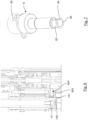
- the rivet support module 200 allows rivets to be held and includes, like the drilling module, a 90 sheath.
- This 90 sheath has a tubular shape and a generally annular section.
- the sheath 90 comprises a lateral finger 900 forming a projection on its lateral wall.
- the sheath 90 comprises a lateral groove 901 which is arranged in a diametrically opposite manner and offset along the longitudinal axis of the sheath relative to the finger 900.
- the sheath houses a tubular element 201 which has at one of its ends a shoulder 202 designed to bear against a shoulder 203 of complementary shape provided at one end of the sheath 90.
- the tubular element 201 which constitutes a chamber, houses a piston 205 which is mounted there to move in translation.
- the piston 205 comprises at one end a collar 206 provided with a circumferential groove 207 housing an O-ring 208. This O-ring 208 ensures sealing between the piston 205 and the tubular element 201.
- the shoulder 204 of the sheath 90 also comprises an internal circumferential groove 209 housing an O-ring 210 ensuring sealing between the piston 205 and the sheath 90.
- the lateral finger 900 of the sheath 90 houses an air duct which extends along the sheath and which is capable of being placed in communication with a pressurized air intake duct 907 arranged in the device, with which it is in communication when it is located at the work station of the device.
- the end of the piston 205 located on the inner side of the shoulder 204 of the sheath 90 comprises a half-dog 211 whose function will be explained later.
- the other end of the piston 205 carries a split ring 212 which constitutes a means of holding the rivet at the end of the piston.
- This split ring 212 has a conical internal bore 213 whose diameter narrows from the inside of the piston 205 towards the outside thereof.
- This conical portion 213 opens onto an internal groove 214 of a shape complementary to that of the end of the head 219 of a rivet 216.
- This groove 214 also opens into a conical inner portion 215 whose diameter narrows towards the outside of the split ring 212.
- This ring 212 has a plurality of longitudinal grooves (not shown) to allow it to deform during the insertion and extraction of a rivet, as will be described in more detail later.
- the split ring 212 comprises at least one external peripheral groove 217 housing an elastic return element such as an O-ring or a spring (not shown) providing a return means function tending, as will be explained in more detail later, to return the ring from a release state in which its internal diameter is enlarged, to a holding state in which its internal diameter is tightened.
- an elastic return element such as an O-ring or a spring (not shown) providing a return means function tending, as will be explained in more detail later, to return the ring from a release state in which its internal diameter is enlarged, to a holding state in which its internal diameter is tightened.
- the tubular element forms, together with the split ring, a fixing element support element.
- the piston is crossed by an internal bore allowing the passage of a rivet.
- rivet support modules can be provided with pistons with different diameter inner bores and different size split rings to allow the holding of rivets of different dimensions.
- the piston 205 is designed to be driven in rotation and/or translation. It thus constitutes a mobile member.
- the piston 205 is movable in translation in the tubular element 201 between a first extreme position in which its shoulder 207 comes into abutment against a circlip 218 provided for this purpose at the end of the tubular element 201 located opposite that located near the shoulder 204 of the sheath, and a second extreme position in which its shoulder 207 comes into abutment against the shoulder 204 of the sheath.
- a module of the rivet support type could be implemented to support another type of fastener such as a screw.
- the split ring would of course have a shape adapted to that of the head of a screw rather than that of the head of a rivet.
- the temporary fixing support module 300 includes a sheath 90.
- This 90 sheath has a tubular shape and a generally annular section.
- the sheath 90 comprises a lateral finger 900 forming a projection on its lateral wall.
- the sheath 90 comprises a lateral groove 901 which is arranged in a diametrically opposite manner and offset along the longitudinal axis of the sheath relative to the finger 900.
- This must 900 houses an air duct 906 which extends along the sheath and which is capable of being put into communication with a pressurized air intake duct 907 arranged in the device, with which it is in communication when it is at the work station of the device.
- the sheath 90 houses a tubular element 301.
- This tubular element 301 has a shoulder 302 at one of its ends bearing against a shoulder 303 formed inside the sheath 90 at one of its ends.
- the tubular element 301 has a second shoulder 304 located near the air duct provided in the finger. This shoulder delimits a smaller diameter portion of the tubular element.
- the tubular element 301 has another end which extends close to a second shoulder 305 provided inside the sheath at the other end thereof.
- a space is however provided between the two to allow the passage of air.
- the tubular element 301 delimits a chamber housing a piston 306.
- This piston 306 comprises at one of its ends a shoulder 307 having a circumferential groove 308 housing an O-ring 309 ensuring sealing between the piston 306 and the tubular element 301.
- the shoulder 305 of the sheath 90 comprises an internal circumferential groove 310 housing an O-ring 311 ensuring sealing between the sheath 90 and the piston 306.
- the piston 306 is mounted to move in translation inside the tubular element 301 and the sheath 90.
- the piston 306 comprises a first bore 312 housing a drive tube 313 (moving member) mounted to move in translation and rotation inside it.
- This drive tube 313 comprises at one of its ends a collar 314 defining a bell 160 crossed by radial holes 161.
- Elastic return means 315 such as for example elastic washers or a spring, are interposed between the collar 314 of the drive tube 313 and the shoulder 307 of the piston 306. These return means tend to move this collar and this shoulder away from each other.
- the bell 160 of the drive tube 313 communicates with a first cylindrical bore 316, which communicates with a second bore 317.
- This second bore houses a first 318 freewheel.
- the second bore 317 communicates with a third bore 320.
- the third bore 320 houses a locking element 321 which is held there by means of a circlip 322 housed on the one hand in a groove 323 provided for this purpose in the drive tube 313 and on the other hand in a groove 324 provided for this purpose in the locking element 321.
- the module comprises means for maintaining a temporary fixing in the module. These means maintain the locking element.
- the compression spring tends to return the locking element 321 to its locking position.
- the first bore 312 of the piston 306 communicates with a second bore 329 comprising a conical portion 331 narrowing towards a cylindrical portion 332.
- the second bore 329 of the piston 306 communicates with a third bore 333 opening out.
- This third bore 333 houses a second freewheel 334 held in place by means of a circlip 335.
- An O-ring 336 ensures the rotational drive between the third bore 333 and the second freewheel 334.
- the first and second freewheels have opposing drive capacities.
- the device includes a single set of 5 drive and control functional modules.
- This drive and control assembly 5 comprises a single drive spindle 51 called the main spindle.
- This spindle is mounted to be movable in rotation and in translation along the same axis, i.e. along its longitudinal axis. The spindle is thus mounted to be movable in translation between a retracted position and a deployed position towards the workstation.
- This assembly 5 also includes motor means 52 capable of driving the drive spindle 51 in movement.
- these motor means comprise a feed motor 510 and a rotation motor 511. They also comprise a transmission T making it possible to drive the spindle 51 in movement via the feed and/or rotation motors according to translation and/or rotation movements along its axis.
- This transmission is of the type comprising a translation drive nut 512 and a rotation drive ring 513.
- the rotation drive ring 513 has an internal bore whose internal periphery comprises keys 5131 of complementary shape to grooves 510 arranged along the spindle 51 along its longitudinal axis. In this way, the spindle 51 and the rotation drive ring 513 are linked in rotation along the axis of the spindle but free in translation along this axis.
- the translation drive nut 512 has a threaded internal bore 5121 of complementary shape to a threaded portion 511 formed along the spindle so that they are linked by a helical connection.
- This type of transmission allows the motor(s) to be shifted laterally in relation to to the spindle.
- the motor(s) are then located next to the spindle rather than in its extension. This improves the compactness of the device, makes it possible to reduce the distance to the center and thus to carry out tasks close to a wall, and also to reduce the overhang.
- the axes of the motors are essentially parallel to the axis of the spindle.
- one or other of these motors, or both may have an axis inclined relative to that of the spindle, in particular orthogonal.
- the device comprises means of equipment for alternately making the drive spindle and at least one movable member of a functional module coupled to the spindle integral in movement.
- the single drive and control assembly 5 typically comprises a controller 53 comprising all the components necessary for controlling the operation of the motors and all the actuators and other sensors of the device.
- a controller includes in particular all the memories, program(s) and processor(s) necessary for controlling the device and performing the various tasks. It also includes communication means (transmitter-receiver) capable of enabling it to receive and transmit data wired or wirelessly. It may also integrate the components necessary for powering the motors (inverter type). It may also include means for entering instructions (keyboard, microphone, touch screen mouse or other), a display screen, means for emitting sound signals, etc. Such a controller may be wholly or partly secured to the frame or placed remotely.
- control means comprise means 530 for measuring the electrical intensity consumed by the motor(s) (current sensor) and for determining, as a function of the measured electrical intensity, a torque and/or an axial force on the spindle and therefore on one or more output members of an equipped functional module. to the spindle.
- This type of means of measuring and determining forces or torques as a function of the current consumed by a motor are known in themselves and not described in detail.
- control means comprise one or more angle sensors 531 integrated into one or more of the motor(s).
- An angle sensor is a sensor for measuring the angular position of the rotor of a motor.
- the control means then comprise means for determining, as a function of the measured angular position of said rotor, the angular position and/or the axial position of said at least one mobile member of a functional module fitted to the spindle.
- This type of means for measuring and determining position as a function of the angular position of the rotor of a motor are known per se and not described in detail.
- the measuring means comprising at least one torque and/or force and/or position sensor 532 integrated into the transmission T and capable of enabling the determination of a torque and/or an axial force on the spindle and/or an angular and/or axial position of the spindle, and therefore by deduction of a torque and/or an axial force and/or an angular position and/or an axial position of the at least one mobile member of a module fitted to the spindle.
- This type of means for measuring and determining forces or torques are known per se and not described in detail.
- Module carrying means carousel
- a device comprises means for carrying a plurality of functional modules. These carrying means make it possible to load and move several functional modules.
- the number of modules that can be loaded is equal to 7 but could alternatively be different (lower or higher). This number could be even or odd.
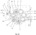
- these carrying means comprise a so-called main carousel 6.
- the main carousel 6 comprises, in the manner of a revolver barrel, a plurality of cells 61 each allowing a functional module to be housed.
- Each cell 61 constitutes a bore opening on either side and extending parallel to the axis of rotation of the carousel.
- the cells 61 are preferably distributed in an essentially uniform manner around the axis of the carousel.
- the device includes several functional positions.
- the carousel not only allows several functional modules to be loaded, it also allows them to be moved from one station to another. For this purpose, it is mounted mobile in rotation around its axis which extends essentially parallel to that of the main spindle as will be described in more detail later.
- the P1 functional module loading/unloading station allows functional modules to be inserted one by one into the carousel's cells and extracted from them.
- the device comprises a jack 13 whose piston 11, which carries a lug 10, is movable in translation in a chamber 12 along an axis orthogonal to the axis of a cell of the carousel brought to the loading/unloading station.
- the device comprises a temporary fixing loading station P2 for inserting a temporary fixing into a temporary fixing support module brought to this station by the carousel.
- the temporary fixing loading station is located at the functional module loading/unloading station. These two stations thus constitute a single dual-function functional station.
- the temporary fixing loading station could however be located at another location.
- This station P2 comprises a temporary fixing supply device 1000.
- This device comprises a cartridge type actuator making it possible to move temporary fixings 1001 in translation until they are placed in the axis of the temporary fixing support module brought to the temporary fixing loading station P2.
- This station P2 also includes a loading jack 1002.
- This jack 1002 is placed in the axis of a temporary fixing support module 300 brought by the carousel 6 to the temporary fixing loading station.
- This jack 1002 is arranged upstream of a temporary attachment 1001 placed by the cartridge belt 1000 in the axis of the temporary attachment loading station P2 to allow action on it to introduce it into the support module 300, as will be explained in more detail later.
- the temporary fixing loading station P2 further comprises a temporary fixing holding device in the temporary fixing support module 300 during its introduction into this module.
- This holding device comprises a fork 1003 essentially L-shaped, the end of which comprises two fingers spaced apart to form a space for receiving a temporary fixing.
- the movement of the fork 1003 is ensured by means of a jack 1005.
- the device includes a P3 rivet loading station.
- This P3 rivet loading station includes a loading cylinder 1006.
- This cylinder 1006 is placed in the axis of a rivet support module brought by the carousel to the rivet loading station.
- This P3 station includes a device for receiving and transferring rivets from a supply (or feed) zone for rivets 1007 (or other fixing element such as screws or other) to a rivet distribution or rivet reception zone such as for example here a rivet support module 200 located at the rivet loading station P3.
- Each cell 1009 constitutes a bore opening out on either side and extending parallel to the axis of rotation of the carousel 1008.
- the cells 1009 are preferably distributed in an essentially uniform manner around the axis of the carousel 1008.
- the number of cells is equal to six. It may of course be greater or less than 6.
- the carousel and its cells form means for receiving fasteners.
- the carousel and its drive means allow fasteners to be moved from a supply area to a distribution area.
- Each cell 1009 has a different diameter so that each cell can accommodate rivets 216 of different sizes.
- Each cell 1009 includes a receiving port 1090 and a dispensing port 1091 for a fastener.
- the receiving port 1090 allows a fastener to be inserted into a cell.
- the dispensing port allows a fastener to be evacuated from the cell.
- the device comprises means for holding a fixing element inserted into a socket. These holding means prevent the extraction, through the receiving orifice, of a fixing element located in a socket.
- the holding means comprise a deformable element 1092 provided with a harpoon-forming tip 1093 located in each cell.
- the tip of each harpoon is shaped to allow the introduction of a fixing element into the cell through its receiving orifice and to prevent the extraction of the fixing element through the receiving orifice of the cell.
- the tip of each harpoon is oriented towards the receiving orifice of the corresponding cell.
- the carousel 1008 is mounted to rotate about an axis essentially parallel to the axis of the main spindle 51, between a support plate 1011 and a rivet holding plate 1012.
- the holding plate constitutes a means for holding elements fixation in the alveoli.
- the support plate 1011 is integral with the frame and fixed relative to it. It is crossed by as many holes 1013 as the carousel 1008 has cells 1009. Each hole has a different diameter corresponding to that of a cell.
- the support plate 1011 carries a shaft 1014 around which the carousel 1008 is mounted to move in rotation.
- One of the holes 1013 of the support plate 1011 is located in the axis of the loading cylinder 1006.
- the holding plate 1012 comprises, in the axis of each hole 1013 of the support plate 1011, air exhaust holes 1015. However, it is crossed by a distribution opening 1080, and not by air exhaust holes 1015, in the axis of the jack 1006.
- the diameter of the distribution opening 1080 allows the passage of the largest rivet capable of being loaded into the secondary carousel.
- the carousel 1008 comprises along its outer peripheral contour longitudinal notches 1016 which extend essentially parallel to the axis of the carousel 1008. These notches form drive teeth as will become more clearly apparent later.
- the device comprises means for driving the carousel in rotation around the shaft.
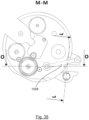
- the piston 1018 of the first cylinder 1017 carries a pawl 1023 which is mounted to move in rotation relative to the piston around an axis 1024 essentially parallel to the axis of rotation of the carousel 1008.
- the pawl 1023 comprises a bearing surface 1025 intended to come into contact with a stop 1026 of the piston 1018 defining the extreme drive position.
- the device comprises a locking pin 8 mounted to move between a locking position in which it is brought into abutment against the carousel 1008 between two consecutive notches 1016 to prevent the carousel from rotating around its axis, and a release position in which it is released from the carousel to allow it to rotate.
- This locking pin 8 is secured to the support plate 1011 by means of a spring blade 1027 which tends to maintain it in its locking position. It constitutes a means for locking and indexing the carousel 1008 in positions in which a cell 1009 of the carousel 1008 is in alignment with the loading cylinder 1006, i.e. in the distribution zone. Preferably, at least one other cell is then located in a feed zone.
- pressurized air is injected into the chamber 1019 so as to move the piston 1018 according to the arrow G into its end position.
- the bearing surface 1025 of the pawl 1023 is in abutment against the stop 1026 of the piston 1018 so that the pawl 1023 is blocked from rotating in the clockwise direction.
- the carousel 1008 is thus rotated in the clockwise direction until the piston 1018 is in abutment in its end position.
- a new cell 1009 of the carousel 1008 is then in alignment with the loading cylinder 1006.
- the blocking pin 8 slides against the peripheral surface of the carousel 1008 and is gradually moved from its locking position to its unlocking position against the effect of the spring blade 1027 and then back into its locking position under the effect of the spring blade 1027 so that the carousel 1008 is kept stationary.
- the cylinder 1017 is actuated according to the arrow H to return to its starting position.
- the pawl 1023 slides against the peripheral surface of the carousel 1008 and gradually passes from its deployed position to its retracted position then to its deployed position by rotating around its axis.
- the carousel 1008 can again be rotated clockwise by repeating this process.
- the piston 1021 of the second cylinder 1020 carries a pawl 1028 which is mounted to move in rotation relative to the piston 1021 around an axis 1029 essentially parallel to the axis of rotation of the carousel 1008.
- the pawl 1028 comprises a bearing surface 1030 intended to come into contact with a stop 1031 of the piston 1021 defining the extreme drive position.
- Return means such as for example a spring or other, may possibly be implemented to act on the pawl 1028 to tend to return it to its deployed position.
- the piston 1021 is in its end position and the pawl 1028 is in its deployed position.
- pressurized air is injected into the chamber 1022 so as to move the piston 1021 according to the arrow I into its end position.
- the bearing surface 1030 of the pawl 1028 abuts against the stop 1031 of the piston 1021 so that the pawl 1028 is blocked from rotating in the counterclockwise direction.
- the carousel 1008 is thus rotated counterclockwise until the piston 1021 is at the stop in its end position.
- a new cell 1009 of the carousel 1008 is then in alignment with the loading cylinder 1006.
- the locking pin 8 slides against the peripheral surface of the carousel 1008 and is gradually moved from its locking position to its unlocking position against the effect of the spring blade 1027 and then back into its locking position under the effect of the spring blade 1027 so that the carousel 1008 is kept stationary.
- the cylinder 1020 is actuated according to the arrow J to return to its starting position.
- the pawl 2018 slides against the peripheral surface of the carousel 1008 and gradually passes from its deployed position to its retracted position and then to its deployed position by rotating around its axis.
- the carousel 1008 can again be rotated counterclockwise by repeating this process.
- the carousel 1008 and the pawls 1023, 1028 form ratchet wheel systems.
- the first 1017 and second 1020 jacks as well as the corresponding pawls 1023, 1028 have opposing movements in that they allow the carousel 1008 to rotate in opposite directions.
- first 1017 and second 1020 jacks make it possible to align the desired cell 1009 with the main spindle 51 more quickly by choosing the direction of rotation of the carousel 1008 which will allow the fastest alignment. However, only one jack can be implemented. This will simplify the device but will lead to longer alignment times.
- the rotational drive means of the secondary carousel 1008 may be of the same type as those of the main carousel 6, which are described later. In this case, rather than using single cylinders to drive the pawls, double cylinders may be used, i.e. external cylinders containing an internal pawl locking cylinder.
- the indexing of the secondary carousel can also be obtained by means of a locking pin controlled by a jack as for the main carousel.
- This device includes means for feeding the carousel with rivets.
- the rivets are fed through a flexible tube and pushed inside this tube by a pressurized gas.
- This P4 coating station is located near the P5 workstation.
- This first pulley 1032 is linked in rotation to the casing of a jack 1036 along an axis essentially parallel to that of the main spindle 51.
- This casing is mounted to be mobile in rotation relative to the frame along the same axis.
- the rod of the piston 1035 of the jack 1036 is linked in rotation with the casing.
- This piston 1035 is mounted to move in translation and in rotation along an axis parallel to the axis of the main spindle 51 inside a chamber 1037. It carries at its end a half-dog 1038 of complementary shape to the half-dog 211 of the rivet support module 200.
- a second pulley 1039 is rotationally connected to the casing of the jack 1036 along an axis essentially parallel to that of the main spindle 51. This second pulley 1039 is rotationally connected by means of a belt 1040 to a third pulley 1041.
- the third pulley 1041 is mounted on a shaft 1042 to which it is rotatably connected.
- the shaft 1042 carries at its end opposite that to which the pulley 1041 is fixed a lead screw 1043.
- This lead screw 1043 comprises a thread whose profile comprises a first flank 1044 intended to mesh with a shoe 1046 and a second flank 1045 inclined relative to the axis of the lead screw.
- the first flank is inclined by a few degrees relative to the perpendicular to the axis of the lead screw in such a direction that, the shoe, being applied to this flank, has a tendency to slide towards the bottom of the net.
- This shoe 1046 is mounted on the end of the piston 1047 mounted to move in translation along an axis essentially orthogonal to the axis of the main spindle 51 in the chamber 1048 of a jack 1049.
- This station comprises mastic distribution means comprising a nozzle 1050 connected to mastic supply means (not shown) comprising a pump connected on the one hand to a mastic reserve and on the other hand to the nozzle 1050 via pipes provided for this purpose.
- mastic distribution means comprising a nozzle 1050 connected to mastic supply means (not shown) comprising a pump connected on the one hand to a mastic reserve and on the other hand to the nozzle 1050 via pipes provided for this purpose.
- the nozzle 1050 comprises a dispensing end 1051 intended to come close to a rivet 216 carried for a rivet support module 200 brought to the coating station P4.
- This end may be straight (extending in a plane perpendicular to an axis perpendicular to the axis of the rivet support module 200).
- This end is however preferably beveled or curved so that the nozzle 1050 can come into abutment against the rivet 216 while providing an orifice for dispensing mastic onto the rivet 216.
- This solution is preferred insofar as it makes it possible to simply and effectively guarantee the calibration of the thread(s) of mastic deposited on the rivet.
- the nozzle 1050 is secured to the end of a piston 1051 mounted to move in translation along an axis perpendicular to the axis of the rivet support module in the chamber 1052 of a jack 1053.
- the shoe 1046, the nozzle 1050 and their respective cylinders 1049, 1053 are mounted in a block 1054 integral with the piston 1055 mounted to move in translation along an axis parallel to the axis of the lead screw 1043 in the chamber 1056 of a cylinder 1057.
- This station comprises means for determining (evaluating) the length of the rivet 216 brought to the coating station.
- These means comprise a feeler 1058.
- One end of the feeler is secured to the piston 1059 mounted to move in translation along an axis parallel to the axis of the lead screw 1043 in the chamber (not shown) of a jack 1060.
- the other end of the feeler 1058 comprises a conical centering tip 1061 oriented towards a rivet 216 brought to the coating station.
- the jack 1060 makes it possible to approach and move the conical tip 1061 away from the rivet 216 to feel its end and thus determine its length.
- the probe 1058 then defines a stop against which the support 1062 of the nozzle 1050 is likely to come to bear to determine a coating limit at the end of the rivet.
- end of the rivet is meant an area located at the end of the body of the rivet opposite the head of the rivet.
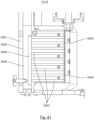
- THE figures 39 to 41 illustrate a variation of the coating station.
- a connector 3011 makes it possible to inject sealant into one of the channels 3003, itself in communication with the groove 3006.
- the probe 3007 which comprises an end 3008 intended to come into contact with the end (foot) of a fixing element, is at its opposite end linked in translation with the drawer 3005.
- the probe 3007 is furthermore linked in translation with the piston 3009 of a jack 3010 whose axis extends essentially parallel to the axis of the main spindle 51.
- the channel 3003 located opposite that located on the end side of a fixing element to be coated extends at the level of the connection zone between the body and the head of this fixing element.
- the nozzle thus makes it possible to distribute sealant in the form of parallel beads on the body of a fastener between its end and the connection zone between its body and its head.
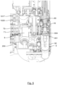
- Workstation P5 is located in the extension of the main spindle 51.
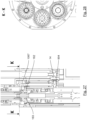
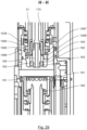
- This station comprises, in addition to the main spindle 51, a secondary spindle 170 mounted to move in translation inside the main spindle 51 which is hollow.
- This secondary spindle 170 is integral with the piston 172 mounted to move in translation along the axis of the main spindle 51 in the chamber 171 of a jack 17.
- the secondary spindle constitutes the rod of this jack.
- the locking key 164 is secured to the end of the secondary pin 170.
- Elastic return means may optionally be implemented to tend to return the locking elements 163 to their unpaired position when the locking key is not acting on them.
- the device comprises a pressurized air intake line 907 which opens into the workstation such that it communicates with the air line 906 of the sheath of a functional module located at the workstation.
- the secondary spindle 170 can be used to perform a telescopic function of different functional modules, such as rivet support modules in particular.
- This telescopic movement makes it possible, as will be described in more detail later, to bring the secondary spindle 170, initially housed in the main spindle in a retracted position, out of the main spindle 51 to reach a deployed position in which it extends at least partly outside the main spindle, then to link them in translation so that the movement of the main spindle 51 is accompanied by a movement of the secondary spindle 170: the main spindle and the secondary spindle then form a single spindle of great length.
- the secondary spindle 170 comprises at its end opposite that of the locking key 164, the piston 172 movable in translation inside the main spindle 51 which constitutes its chamber 171 of the jack 17.
- the secondary spindle 170 comprises a circumferential groove 1063 downstream of the piston 172.
- the device comprises means for connecting in translation said internal pin with said external pin.
- the main pin 51 carries an unlocking ring 1064.
- This unlocking ring 1064 is fixed in translation with the frame. It is linked in rotation with the main spindle by means of grooves (not shown) which also allow the main spindle to translate inside the locking ring 1064.
- the locking ring 1064 is linked in rotation with the drive pulley 1034.
- This unlocking ring 1064 comprises a bore with a cylindrical portion 1065 followed by a truncated cone portion 1066 widening towards an opening opening on the side of the pin 51 oriented towards a functional module brought to the workstation.
- the main spindle 51 carries a locking member.
- This locking member comprises a locking ring 1067 mounted on the male element 162.
- This locking ring 1067 is crossed by a hole 1068 whose diameter allows the passage of the locking key 164 and the secondary pin 170.
- the locking ring 1067 has two opposing cut sides 1073 and is mounted in a complementary shaped groove 1074 formed in the male element 162.
- the first groove portion 1070 forms, with a second peripheral groove portion 1070' provided on the male element, a peripheral groove housing an elastic return element such as for example an O-ring or a spring.
- the passage into the unlocking position is obtained by introducing the portion of the male element 162 carrying the locking ring 1067 into the conical portion 1066 then into the cylindrical portion 1065 of the unlocking ring 1064 which thereby acts on the locking ring 1067 to move it relative to the male element 162 against the effect of the compression spring.
- the secondary spindle 170 is then linked in translation with the main spindle 51 so that the translational movement of the main spindle 51 is accompanied by a translational movement of the secondary spindle 170 which together form a single spindle of great length.
- the carousel is mounted to rotate about its axis which extends essentially parallel to that of the spindle.
- the carousel comprises along its outer peripheral contour longitudinal notches 62 which extend essentially parallel to the axis of the carousel. These notches form drive teeth as will become more clearly apparent later.
- the device comprises means for driving the carousel to rotate around its axis.
- the piston 700 of the first cylinder 70 carries a pawl 702 which is mounted to move in rotation relative to the piston 700 around an axis 703 essentially parallel to the axis of rotation of the carousel.
- the pawl 702 comprises a bearing surface 704 intended to come into contact with a stop 705 of the piston 700 defining the extreme drive position.
- Return means such as a spring or other, may possibly be used to act on the pawl to tend to return it to its deployed position.
- the piston 700 comprises an inner chamber 706 in which an inner piston 707 is housed, the end 708 of which is beveled.
- the piston 700 is in its end position and the pawl is in its deployed position.
- An elastic return means such as for example a spring (not shown), acts on the pin 8 to tend to return it to its locking position.
- a jack 800 makes it possible to lock the locking pin 8 in its locking position.
- the jack 800 is exhausted so that the locking pin 8 is held in its locking position by the sole effect of the spring.
- the piston 700 is in its starting position (stopped to the right on the Figure 12 ).
- the 702 ratchet is in its deployed position.
- the internal piston 707 is in its locking position so that the pawl 702 is held in its deployed position without being able to rotate around its axis 703.
- Pressurized air is then injected into the chamber 701 so as to move the piston 700 according to the arrow B from its starting position to its end position.
- the pawl meshes with the notch in which it is located so that the carousel is thus rotated counterclockwise.
- the locking pin 8 slides against the peripheral surface of the carousel so that it gradually passes from its indexing position to its release position and then from its release position to its indexing position when the piston 700 is at the stop in its end position.
- the cylinder 800 is powered to lock the locking pin in its indexing position so that the carousel is kept stationary. At least one new cell 61 of the carousel is then at a functional position.
- the internal piston 707 is moved into its unlocked position so that the pawl is free to rotate around the axis 703 (within the limits of the travel permitted by its shape and the surfaces surrounding it).
- the cylinder 70 is actuated so that the piston 700 moves according to the arrow A to be returned to its starting position.
- the pawl 702 gradually moves from its deployed position to its retracted position and then from its retracted position to its deployed position by sliding against the peripheral surface of the carousel and pivoting around the axis 703 clockwise until the piston is in its starting position.
- the pawl is then housed in another notch 62 of the carousel.
- the carousel can be rotated counterclockwise again by repeating this process.
- the piston 710 of the second cylinder 71 carries a pawl 712 which is mounted to move in rotation relative to the piston 710 around an axis 713 essentially parallel to the axis of rotation of the carousel.
- the pawl 712 thus comprises a bearing surface 714 provided to come into contact with a stop 715 of the piston 710 defining the extreme drive position.
- Return means such as a spring or other, may possibly be used to act on the pawl to tend to return it to its deployed position.
- the piston 710 comprises an interior chamber 716 in which is housed an internal piston (not shown) whose end is beveled like the internal piston 707.
- the piston 710 is in its starting position and the pawl 712 is in its deployed position.
- the jack 800 is exhausted so that the locking pin 8 is held in its locking position by the sole effect of the spring.
- the 712 ratchet is in its deployed position.
- the internal piston is in its locking position so that the pawl is held in its deployed position without being able to rotate around its axis 713.
- Pressurized air is then injected into the chamber 711 so as to move the piston 710 according to the arrow A then from its starting position to its end position.
- the pawl meshes with the notch in which it is located so that the carousel is thus driven into rotation in a clockwise direction.
- the locking pin 8 slides against the peripheral surface of the carousel so that it passes progressively from its indexing position to its release position and then from its release position to its indexing position when the piston 710 is at the stop in its end position.
- the cylinder 800 is powered to lock the locking pin in its indexing position so that the carousel is kept stationary. At least one new cell 61 of the carousel is then at a functional position.
- the internal piston is moved into its unlocked position so that the pawl is free to rotate around the axis 713 (within the limits of the travel permitted by its shape and the surfaces surrounding it).
- the cylinder 71 is actuated so that the piston 710 moves according to the arrow B to be returned to its starting position.
- the pawl 712 gradually moves from its deployed position to its retracted position and then from its retracted position to its deployed position by sliding against the peripheral surface of the carousel and pivoting around the axis 713 in the counterclockwise direction until the piston is in its starting position.
- the pawl is then housed in another notch 62 of the carousel.
- the carousel can be rotated clockwise again by repeating this process.
- the carousel and pawls form ratchet wheel systems.
- the first 70 and second 71 jacks and the corresponding pawls have opposing movements in that they allow the carousel to rotate in opposite directions.
- first 70 and second 71 jacks allow a module to be placed at the desired functional position as quickly as possible by choosing the direction of rotation of the carousel which will ensure the shortest path. However, only one jack can be implemented. This will simplify the device but will lead to longer alignment times.
- the rotational drive means of the main carousel may be of the same type as those of the secondary carousel. In this case, rather than using double cylinders to drive the pawls, i.e. external cylinders containing an internal pawl locking cylinder, single cylinders may be used.
- the indexing of the secondary carousel can also be obtained by means of a locking pin not controlled by a jack as for the secondary carousel.
- the carousel 6 is mounted to move in rotation around a fixed shaft 8 on which it is guided in rotation by means of a needle, ball or other bearing 87.
- the shaft 8 is hollow and comprises at one of its ends a widened portion defining a chamber 81 in which a piston 82 of a jack 80 slides.
- the shaft 8 comprises at the other of its ends a circumferential groove 83 and is crossed by a lateral light 84 communicating with the hollow interior of the shaft.
- the shaft further comprises at this end a flat 85 which opens into the groove 83.
- a guide element 14 is secured to the end of the rod 820 of the piston 82.
- This guide element 14 comprises a projecting portion 140 which extends inside the light 84 of the shaft 8.
- a groove 141 is provided at the end of the projecting portion 140. This groove 141 extends in the extension of the groove 83 of the shaft with which it forms a circular groove.
- the sheath 90 of each functional module is designed to be slidably mounted inside the cells 61 of the carousel 6.
- the end of the lateral finger 900 of each of the sheath 90 of each functional module is designed to be housed, depending on the angular position of the carousel 6, alternately in the groove 83 of the shaft 8 and in the groove 141 of the guide element 14 so that the sheath is held integral with the shaft 8 or the piston 82 along the axis of rotation of the carousel 6, and is thus immobilized in translation along the axis of the cell in which it is located.
- the projecting portion 140 and the grooves 141 and 84 extend to an angular position corresponding to the finger 900 of a sheath 90 of a functional module 9 located at the work station in the extension of the spindle 51.
- each sheath 90 is capable of housing the lug 10 placed at the end of the piston 11 movable in translation in the chamber 12 of the jack 13.
- the jack 13 is located at a loading/unloading station of the carousel 6. This station is located in such a way that when a cell 61 of the carousel is located at the work station in the extension of the spindle 51, another cell is located at the loading/unloading station (i.e. at the staple loading station in this embodiment), another cell is located at the rivet loading station and another cell is located at the coating station.
- the flat 85 and the lug 10 extend along axes parallel and perpendicular to the axis of rotation of the carousel 6.
- the loading of the carousel 6 into functional modules 9 is obtained in the following manner.
- Pressurized air is injected into the chamber 12 of the cylinder 13 so as to move the piston 11 according to the arrow C in order to release the lug 10 from inside the cell 61 located at the loading/unloading station.
- the cylinder 1005 is actuated to place the fork 1003 in its release position.
- a module is introduced inside the cell 61 located at the loading/unloading station through the side of the carousel 6 located on the side of the end of the shaft 8 where the groove 84 is located.
- the finger 900 of the sheath 90 is introduced into the groove 83 passing through the flat 85 which forms an insertion passage.
- Air is then introduced into the chamber 12 of the cylinder 13 so as to move the piston 11 according to the arrow D to introduce the lug 10 into the groove 901 of the sheath 90.
- the sheath 90, and therefore the corresponding functional module 9, is thus held in the cell 61 along the axis of which it is blocked in translation.
- this groove 901 allows the sheath to arrive at the loading/unloading station and to leave this station while the lug 10 projects into the groove 901.
- the carousel 6 can then be rotated to place the next cell at the loading/unloading station and the process is repeated to load a new functional module 9.
- the main carousel It is thus possible to load all seven, or more generally all, of the cells of the main carousel. However, only certain cells can be loaded as needed. It is also possible, in other embodiments, for the main carousel to comprise more or fewer than seven cells.
- the unloading of a functional module 9 is obtained, after having placed the corresponding cell at the loading/unloading station, by actuating the jack 13 to release the lug 10 from the groove 901 and thus allow the functional module 9 to slide out of the corresponding cell 61.
- the device comprises a tubular-shaped pressing element 15 mounted to move in translation relative to the frame 2 along the axis of movement of the spindle 51 and in the extension thereof.
- a pressing element 15 can for example be used during a drilling operation to exert a compressive force on the structure to be drilled, in particular to ensure contact between the plates of a stack and to avoid the formation of burrs between these plates during drilling.
- the robot arm to which the device is attached is operated to place the multi-task device so that the workstation is positioned at the location of the structure to be worked on where an operation is to be carried out.
- the robot applies the device against the structure to be worked until the suction cups 41 come to bear against the surface of the latter. A vacuum is then created in the suction cups to ensure an effective connection between the multi-task device and the structure to be worked.
- a 42 clamping C can be used as an alternative to suction cups.
- the main carousel In order to carry out a drilling and/or milling operation, the main carousel is rotated until the desired drilling module is located at the workstation.
- the elastic return means tend to bring the piston 903 of the jack back into a position in which its end 905 is housed in the housing 950 or projects into the sheath to prevent the functional assembly of the drilling module from sliding in the sheath, the end 905 of the piston 903 coming into contact with the end 951 of the bearing 95.
- the drilling and/or milling module 9 must then be coupled to the drive spindle 51 so that the latter can drive the output shaft 91 which constitutes a moving member of the module.
- the spindle 51 is driven in translation along its axis in the direction of the functional module placed at the workstation until the male element 162 is housed in the bell 160.
- Pressurized air is injected into the chamber 171 of the jack 17 in order to move the internal spindle 170 according to the arrow E.
- the ramp 165 of the locking key 164 then acts on the locking elements 163 to place them in their fitting position in which they cooperate with the radial holes 161 of the bell 160.
- the spindle 51 and the output shaft 9 are then linked in rotation and in translation.
- the angular position of the male element 162 relative to the bell 160 is random and consequently the locking elements may not be perfectly aligned with the radial holes of the bell.
- the spherical heads of the locking elements make it possible to induce a slight relative rotation of the bell with respect to the male element causing the holes of the bell and the male element to become coaxial and thus allowing the locking elements to penetrate into the holes of the bell.
- the resistive torque resulting from the first drilling operation would then induce a relative rotational movement of the male element and the bell to align the locking elements with the radial holes and finalize the fitting.
- the cylinder 904 is actuated to extract the end 905 of its piston 903 from the housing 950 of the bearing 95 or so that the end 905 no longer projects inside the sheath.
- the pressing element then follows the same movement, causing it to press against the structure to be worked and exert a pressure force on the structure to be worked.
- the force of pressing the pressing element 15 against the surface to be worked is maintained by the jack 80 while the translational movement of the spindle 51 according to the arrow E is accompanied by a movement of the mobile assembly inside the sheath which is then immobile in translation according to the arrow E.
- the spindle 51 can then be driven in rotation and translation and transmit its movements to the output shaft 91 of the functional module 9 fitted to carry out the operation. desired drilling.
- the main spindle and output shaft assembly here constitute a rotational and translational connection.
- a rivet support module 200 Prior to carrying out a rivet setting operation, whether or not preceded by a mastic coating operation, a rivet support module 200 must be loaded with a rivet 216.
- the main carousel 6 is rotated so as to bring to the rivet loading station P3 the rivet support module 200 corresponding to the size of the rivet 216 that is to be placed and, if necessary, coated.
- the cell 1009 of the secondary carousel 1008 corresponding to the size of this rivet 216 is supplied with a rivet by the rivet supply means of the carousel 1008.
- the rivets are brought through a flexible tube pushed inside this tube by a pressurized gas.
- the secondary carousel 1008 is then rotated so as to place the cell 1009 containing the rivet at the rivet loading station P3.
- Pressurized air is injected into the air line 906 of the rivet support module 200 so as to maintain its piston 205 in its first extreme position in abutment against the circlip 218 on the side opposite the split ring.
- the jack 1006 is then operated to push the rivet 216 contained in the cell 1009 inside the rivet support module 200 until the head 219 of the rivet 216 is housed in the split ring 213.
- the head 219 of the rivet 216 acts on the split ring 213 to widen it so as to be housed in the groove 214 and in the conical bore 215 of the split ring 213.
- the ring 213 then tightens around the head 219 of the rivet 216 under the effect of the O-rings implemented for this purpose so that the rivet 216 can no longer exit the ring 213 by following the reverse path.
- the rivet 216 is then held in the rivet support module 100 and its body 220 projects outside the module 200 beyond the split ring 213.
- the rivet support module 200 previously loaded with the rivet 216 which is to be coated with mastic is brought to the coating station P4 by rotating the main carousel 6.
- a helical type coating consists of depositing at least one annular bead of mastic at the end 221 of the rivet, at least one annular bead of mastic under the head 219 of the rivet and a helical bead along the body 220 of the rivet between the end and the head of the rivet.
- the support 1062 of the nozzle 1050 is then in abutment against the probe 1058.
- the chamber of the cylinder 1057 carrying the block 1054 is exhausted.
- the cylinder 1036 is actuated so as to engage the half-claw 1038 that it carries with the half-claw 211 of the piston of the rivet support module 100 placed at the coating station.
- the piston here constitutes a movable member and the cooperation of the two half-claws constitutes an indirect coupling of the main spindle with this movable member.
- the coupling here is a rotational connection.
- each rivet support module is suitable for supporting a rivet of a given size.
- each rivet support module The length along the axis of the pin 51 of the piston 205 of each rivet support module is determined according to the size of the rivet that it is intended to support so that, when the cylinder 1036 carrying the half-claw 1038 reaches the end of its stroke, the connection zone between the head 219 and the body 220 of the rivet carried by a module is always at the same given position along the axis of the pin 51.
- the jack 1060 is actuated to move the feeler 1058 towards the head 219 of the rivet until the conical tip 1061 comes to bear against the end 221 of the rivet, thus stopping the travel of the jack 1060.
- the feeler 1058 against which the nozzle 1050 is in abutment, thus moves the nozzle to the end 221 of the rivet (at a predetermined distance from the end of the rivet).
- the cylinder 1053 moves the nozzle 1050 toward the rivet body 220 until its tip contacts the rivet body.
- the main spindle 51 is driven in rotation so as to drive in rotation via the pulleys and belts on the one hand the piston 205 of the module and therefore the rivet that it carries but also the lead screw 1043 at time t0.
- the sealant pump is operated so that the nozzle 1050 delivers sealant to the end 221 of the rivet.
- the shoe 1046 is moved to its meshing position with the lead screw 1043 by means of the jack 1049.
- the contact between the shoe 1046 and the surface 1045 of the thread 1044 of the lead screw 1043 is finalized after a fraction X of a turn of the lead screw 1043.
- This fraction of a turn is necessary insofar as when the shoe comes into contact with the screw, it is in a random relative position such that a space between the shoe and the flank of the thread remains.
- the translational drive of the shoe by the lead screw is only effective after this space has been absorbed under the action of a random fraction of a turn X.
- the nozzle 1050 When the shoe 1046 is in its engaging position, i.e. after finalization of contact between the shoe and the lead screw, the nozzle 1050 then begins to move towards the head 219 of the rivet and the nozzle 1050 begins to deposit a spiral bead of sealant along the body 220 of the rivet.
- the nozzle 1050 arrives at the height of the connection between the body 220 and the head 219 of the rivet.
- the length of cord deposited on the end can be 2 turns at most, justifying the total number of turns of 3 + Y to have at least a deposit of 1 turn under the head.
- the shoe 1046 is moved into its disengagement position by means of the jack 1049.
- the nozzle 1050 is moved away from the rivet body 220 by means of the jack 1053.
- the nozzle 1050 and the feeler 1058 are brought into the extreme position on the side of the end 221 of the rivet respectively thanks to the extension of the jacks 1057 and 1060.
- the main carousel 6 is rotated to bring the mastic-coated rivet to the rivet setting station at which there is a rivet setting device.
- An annular type coating consists of depositing at least one annular bead of mastic under the head 219 of the rivet.
- the jack 1036 is actuated so as to engage the half-dog 1038 which it carries with the half-dog 211 of the rivet support module 100 placed at the coating station.
- each rivet support module is capable of supporting a rivet of a given size.
- the length along the axis of the piston pin of each rivet support module is determined according to the size of the rivet that it is intended to support so that, when the cylinder carrying the half-claw reaches the end of its stroke, the connection zone between the head and the body of the rivet carried by a module is always at the same given position.
- the jack 1060 is actuated to move the feeler 1058 towards the head 219 of the rivet until the conical tip 1061 comes to bear against the end 221 of the rivet, thus stopping the travel of the jack 1060.
- the jack 1057 is actuated to come into abutment at its end on the side of the rivet head 219, thus stopping the nozzle 1050 at the height of the connection between the body 220 and the rivet head 219.
- the cylinder 1053 moves the nozzle 1050 toward the rivet body 220 until its tip contacts the rivet body 220.
- the main spindle 51 is driven in rotation so as to drive in rotation via the pulleys and belts on the one hand the piston 205 of the module and therefore the rivet which it carries.
- the sealant pump is operated so that the nozzle 1050 delivers sealant to the connection area between the head 219 and the body 220 of the rivet.
- the rotation of the main spindle 51 is stopped after having given the rivet a rotation of at least one turn, at which point a bead of at least one turn is deposited under the rivet head 219.
- the sealant application is deactivated by depressurizing the sealant pump.
- the nozzle 1050 is moved away from the rivet body 220 by the retraction of the cylinder 1053.
- the main carousel 6 is rotated to bring the putty-coated rivet to the work station for setting the rivet.
- the cylinder 3010 is actuated to move the probe 3008 along the arrow E to its extreme position.
- a rivet support module carrying a rivet to be coated is then brought to the coating station.
- the half-dog 1038 is moved to the stop by the corresponding jack so as to engage with the half-dog 211 of the module and to move the piston of the module into a position in which the connection zone of the rivet that it carries is in alignment with the channel 3003 of the nozzle located opposite that located on the side of the end of the rivet.
- the jack 3010 is actuated according to the arrow F so that the end 3008 of the feeler comes into contact with the end of the rivet.
- the drawer 3005 then slides inside the chamber 3002 so as to close the channels which extend beyond the end of the rivet.
- the rivet is then rotated on a lathe while the sealant pump is operated to dispense sealant. This allows a plurality of annular beads of sealant to be deposited on the rivet body simultaneously, parallel to each other between the end and the connection area of the rivet.
- the rotation of the rivet is stopped, the pump is stopped, the jack is actuated according to arrow E to move the feeler away from the rivet and then the main carousel is actuated to move the module carrying the coated rivet to the workstation to place the rivet.
- the device can be used to install rivets, whether or not previously coated with mastic, depending on the case. It therefore includes a rivet installation device.
- the main spindle 51 is driven in translation along its axis via the feed motor.
- the main pin 51 then comes to bear against the piston 205 of the rivet support module 200 so that the latter moves in translation inside the chamber. from a retracted position in which it extends inside the sheath to a deployed position in which it extends at least partly outside the sheath until it comes to a stop at the bottom of the latter and the sheath translates in the cell of the carousel over a sufficient distance to engage the end 221 of the rivet in the corresponding hole (in the case of a rivet with a threaded end, the insertion of the threaded portion may be sufficient).
- the module piston constitutes a moving part and the apparatus here constitutes a simple contact between the main spindle and the moving part so as to drive it in translation in one direction.
- the feed motor is then driven to move the main spindle 51 in the opposite direction.
- the main spindle 51 is translated until it reaches its extreme position in which the portion of the male element 162 carrying the locking ring 1067 is housed in the cylindrical portion 1065 of the unlocking ring 1064 which acts on the unlocking ring 1067 to move it into its unlocking position.
- the secondary spindle 170 is then translated inside the main spindle 51 by feeding the chamber of its jack 17 (until it comes into contact with the head of the rivet).
- the secondary spindle 170 is then linked in translation with the main spindle 51 so that the translational movement of the main spindle 51 is accompanied by a translational movement of the secondary spindle 170 which together form a long spindle.
- the locking key 164 then pushes on the head 219 of the rivet to extract it from the clamp and insert it completely into the hole.
- the rivet is thus evacuated from the module by evacuation means which allow it to be inserted into a hole and which in this embodiment include in particular the pins main and secondary.
- Reading the currents of the motors driving the main spindle, in this case the feed motor, makes it possible to know the thrust effect on the rivet and to stop the progression of the main spindle when the thrust effect becomes greater than a predetermined threshold corresponding to total insertion of the rivet into its hole.
- the main pin 51 is moved to its extreme position in which the portion of the male element 162 carrying the locking ring 1067 is housed in the cylindrical portion 1065 of the unlocking ring 1064 which thereby acts on the external surface of the lateral actuating portion 1069 to move the locking ring 1067 relative to the male element 162 against the effect of the compression spring into its unlocking position.
- the secondary spindle 170 is then returned to the main spindle 51 by actuating its jack 17.
- the piston 205 of the rivet support module is returned to the sheath by supplying its chamber with compressed air until it comes into abutment against the circlip 218 and the sheath 90 is returned to its socket thanks to the action of the jack 80.
- a device according to the invention can be used to carry out the installation of temporary fixings.
- a temporary fastener 2000 typically comprises a body 2001, a deformable (expandable and retractable) harpoon-tipped end 2002 having a longitudinal slot and containing a spreader element fixed relative to the body, and a rotating element 2003 which, when rotated relative to the body, causes the harpoon to spread apart (expand) and then retract into the body.
- the rotating element when, after being inserted into a hole passing through two sheets, the rotating element is rotated and tightened relative to the body, the harpoon moves away from the other side of the sheets relative to the body and then enters the body and causes the sheets to be pressed against each other.
- An illustrative and non-limiting example of a temporary fastener is described in the document US 4,548,533 .
- the temporary fasteners according to the invention comprise a body and a rotating element of cylindrical section and of the same diameter and having smooth and uniform external surfaces.
- the body and the rotating element are separated by a space (housing) to allow them to be locked in position as will be described in more detail elsewhere.
- a temporary fixing support module 300 Prior to performing a temporary fixing installation operation, a temporary fixing support module 300 must be loaded with a temporary fixing.
- the main carousel 6 is rotated so as to bring the temporary fixing support module to the loading station P2.
- the cylinder 1005 is actuated to place the fork 1003 in its holding position.
- the cartridge belt 1000 is implemented to place a temporary attachment 2000 in the axis of the temporary attachment support module.
- the chamber of the temporary fixing support module is supplied with compressed air so as to maintain the piston 306 in a release position in which its shoulder 307 is close to the collar 314 of the drive tube 313.
- the surface of the conical bore 331 of the piston 306 acts on the locking element 321 to maintain it in its rest position in which the end of the locking lug 327 is distant from the longitudinal axis of the drive tube.
- the loading cylinder 1002 is activated in such a way that the end of its rod comes out of its chamber to push the head of the rotating element 2003 of the temporary fixing so as to introduce the temporary fixing into the temporary fixing support module until the female part 2001 comes into abutment against the fork 1003.
- the rotating element 2003 of the temporary attachment is then engaged with the first freewheel 318 while the body 2001 is engaged with the second freewheel 33'.
- the chamber of the temporary fixing support module is vented so that the piston 306 moves away from the collar 314 under the effect of the spring 315 until it reaches a locking position.
- the locking element 321 returns to its locking position under the effect of the spring housed in the housing 328: the end of the locking lug 327 is then housed in the space E between the head of the rotating element 2003 and the body of the temporary fixing so that the latter is blocked in translation inside the module along its longitudinal axis.
- the loading cylinder 1002 is then retracted to its starting position and then the cylinder 1005 is actuated so as to return the fork 1003 to its release position.
- the device allows the installation of temporary fasteners and thus includes a temporary fastener installation device.
- a temporary fixing support module in which a temporary fixing has been inserted is brought with the main carousel to the workstation.
- the temporary fixing support module must then be fitted to the main spindle.
- the spindle 51 is driven in translation along its axis in the direction of the functional module placed at the workstation until the male element 162 is housed in the bell 160.
- a slight air pressure can be introduced into the module chamber so that the piston 306 exerts a counter force along the longitudinal axis of the module with respect to the fitting force.
- Pressurized air is injected into the chamber 171 of the jack 17 in order to move the internal spindle 170 according to the arrow E.
- the ramp 165 of the locking key 164 then acts on the locking elements 163 to place them in their fitting position in which they cooperate with the radial holes 161 of the bell 160.
- the spindle 51 and the drive tube are then linked in rotation and in translation.
- the drive tube is a movable member and the fitting of the latter with the main spindle is a connection in rotation and in translation.
- connection between the spindle and the moving member i.e. the output shaft or the drive tube
- the spindle and the output shaft or the drive tube are interconnected directly via the connection means 16 without intermediate transmission.
- An intermediate transmission could however be interposed between the moving member and the bell 160.
- Such an intermediate transmission could or could not serve as a gear reducer. It could not induce a transformation of movement or on the contrary induce a transformation of movement (for example transformation of a translational movement of the spindle into a rotational movement of at least one moving member of a functional module).
- the connection between the moving part (the module piston) and the spindle is made indirectly at the coating station via pulleys, belts and half-dogs. It is made directly by simple contact at the work station.
- the sensors of the control and measurement system can be used to record parameters specific to the operation of the fitted module.
- the axial thrust measurement can also be used to detect the cooperation of the male element 162 and the bell 160 during the fitting of a functional module.
- the functional modules therefore preferably do not include any sensors, or at least a very limited number of sensors, which makes their structure particularly simple, robust and economical.
- the device also comprises a battery of pneumatic connectors 18 making it possible to connect all of the pneumatic actuators to means for supplying pressurized fluid and/or to means for creating a vacuum.
- the device according to the invention makes it possible to perform a plurality of functions, for example, installing a fixing element, coating a fixing element, drilling, etc. In this sense, it constitutes a multi-task device. It thus comprises devices making it possible to perform each of the functions, in particular a coating device, a temporary fixing installation device, a fixing element installation device, a drilling device, a fixing element transfer device, etc. Each of these devices can be separated to form an independent device performing its own function. Any combination of several (in particular at least 2) of these devices can be produced.
Landscapes
- Engineering & Computer Science (AREA)
- Mechanical Engineering (AREA)
- Insertion Pins And Rivets (AREA)
- Automatic Assembly (AREA)
- Actuator (AREA)
Claims (16)
- Vorrichtung (1) zum Setzen von Nieten in eine in einer zu bearbeitenden Struktur ausgebildete Öffnung, wobei die Vorrichtung zumindest Folgendes umfasst:- ein Niettragemodul (200), das dazu geeignet ist, einen Niet (216) zu enthalten;- Mittel (6) zum Bewegen des Moduls (200) zumindest zwischen einer Nietladestation (P3) und einer Arbeitsstation (P5) zum Setzen von Nieten;- Mittel (1006, 1007, 1008) zum Einführen eines Niets (216) in das Innere des Moduls (200) an der Nietladestation (P3);- Mittel (51, 170) zum Entnehmen eines in dem Modul (200) enthaltenen Niets (216) aus selbigem an der Arbeitsstation (P5), wobei die Mittel (51, 170) zum Entnehmen dazu ausgelegt sind, den Niet (216) in die Öffnung einzusetzen,dadurch gekennzeichnet, dass das Modul (200) eine Hülse (90) umfasst, die einen Kolben (205) aufnimmt, der im Inneren der Hülse (90) translatorisch beweglich montiert ist zwischen zumindest:- einer eingefahrenen Stellung, in der er sich im Inneren der Hülse (90) erstreckt, und- einer ausgefahrenen Stellung, in der er sich zumindest teilweise außerhalb der Hülse (90) erstreckt, wobei das Modul (200) Mittel (212) zum Halten (216) des Niets am Ende des Kolbens (205) umfasst,wobei die Mittel zum Entnehmen eine teleskopische Spindel (51, 170) umfassen, die entlang der Achse des Moduls (200) translatorisch beweglich montiert ist und ein Ende umfasst, das dazu bestimmt ist, mit einem im Modul (200) angeordneten Niet (216) in Kontakt zu kommen, wobei die Vorrichtung Mittel (510, T) zum translatorischen Antrieb der Spindel (51, 170) umfasst.
- Vorrichtung nach Anspruch 1, wobei die Mittel zum Entnehmen (51, 170) über zwei aufeinanderfolgende Hübe des partiellen Voreinsetzen und dann des vollständigen Endeinsetzens des Niets (216) in die Öffnung beweglich sind, während derer das Ende des Niets (216) und dann der Körper des Niets (216) nacheinander in die Öffnung eingesetzt werden.
- Vorrichtung nach Anspruch 1 oder 2, wobei die teleskopische Spindel Folgendes umfasst:- eine äußere Hauptspindel (51), die translatorisch beweglich montiert ist zwischen zumindest:- einer eingefahrenen Stellung und- einer ausgefahrenen Stellung in Richtung des an der Arbeitsstation (P5) angeordneten Moduls (200) und- eine innere Sekundärspindel (170), die im Inneren der äußeren Spindel (51) translatorisch beweglich montiert ist zwischen zumindest:- einer eingefahrenen Stellung, in der sie im Inneren der äußeren Spindel (51) untergebracht ist, und- einer ausgefahrenen Stellung, in der sie sich zumindest teilweise außerhalb der äußeren Spindel (51) erstreckt.
- Vorrichtung nach Anspruch 3, wobei die äußere Spindel (51) ein Ende umfasst, das auf den Kolben (205) wirken kann, wenn die äußere Spindel (51) in eine ausgefahrene Stellung verschoben wird und die innere Spindel (170) ihre in die äußere Spindel (51) eingefahrene Stellung einnimmt, um den Kolben (205) in seine ausgefahrene Stellung zu bewegen, sodass der Niet (216), der mit dem an der Arbeitsstation (P5) befindlichen Modul (200) fest verbunden ist, teilweise in die Öffnung eingesetzt wird.
- Vorrichtung nach Anspruch 3 oder 4, umfassend Mittel zur translatorischen Verbindung der inneren Spindel (170) mit der äußeren Spindel (51), wobei die Mittel zur translatorischen Verbindung zumindest folgende Stellungen einnehmen können:- eine Entriegelungsstellung, in der die innere Spindel (170) im Inneren der äußeren Spindel (51) frei gleiten kann, und- eine Verriegelungsstellung, in der die innere Spindel (170) und die äußere Spindel (51) translatorisch miteinander verbunden sind.
- Vorrichtung nach Anspruch 5, wobei die Mittel zur translatorischen Verbindung einen Verriegelungsring (1067) umfassen, der beweglich ist zwischen:- der Verriegelungsstellung, in der er mit einer komplementär geformten Aufnahme (1063) zusammenwirkt, die in der inneren Spindel (170) ausgebildet ist, und- der Entriegelungsstellung, in der er nicht mit der Aufnahme (1063) zusammenwirkt.
- Vorrichtung nach Anspruch 6, wobei es sich bei der in der inneren Spindel (170) ausgebildeten Aufnahme um eine Umfangsnut (1063) handelt und der Verriegelungsring (1067) entlang einer Achse, die im Wesentlichen senkrecht zu der der inneren Spindel (170) verläuft, translatorisch beweglich ist.
- Vorrichtung nach Anspruch 6 oder 7, umfassend elastische Rückstellmittel, die dazu neigen, die Mittel zur Verbindung (1067) in die Verriegelungsstellung zurückzubringen, und Entriegelungsmittel (1064), die es ermöglichen, die Mittel zur Verbindung (1067) in ihre Entriegelungsstellung zu bringen.
- Vorrichtung nach Anspruch 8, wobei die Entriegelungsmittel einen Entriegelungsring (1064) umfassen, der mit einer kegelstumpfförmigen Bohrung (1066) versehen ist, die sich in Richtung des an der Arbeitsstation (P5) angeordneten Moduls (200) erweitert, wobei der Entriegelungsring (1064) drehbar mit der äußeren Spindel (51) verbunden ist, wobei der Verriegelungsring (1067) im Entriegelungsring (1064) untergebracht ist, wenn sich die äußere Spindel (51) in ihrer eingefahrenen Stellung befindet, wobei die Wände der kegelstumpfförmigen Bohrung (1066) auf den Verriegelungsring (1067) wirken, um ihn in seine Entriegelungsstellung zu bringen.
- Vorrichtung nach Anspruch 9, umfassend Steuermittel, die dazu ausgelegt sind, nacheinander:- die äußere Spindel (51) und die innere Spindel (170) in ihre eingefahrene Stellung zu bewegen;- die Hauptspindel (51) in ihre ausgefahrene Stellung zu bewegen, um den Kolben (205) eines an der Arbeitsstation (P5) angeordneten Moduls (200) in seine ausgefahrene Stellung zu bewegen, um einen mit dem Modul (205) fest verbundenen Niet (216) teilweise in die Öffnung der zu bearbeitende Struktur einzusetzen;- die Hauptspindel (51) in ihre eingefahrene Stellung zu bewegen, um den Verriegelungsring (1067) in seine Entriegelungsstellung zu bringen;- die Sekundärspindel (170) in ihre ausgefahrene Stellung zu bewegen, in der ihr Ende am Kopf des teilweise in die Öffnung eingesetzten Niets (216) anliegt;- die Hauptspindel (51) in ihre ausgefahrene Stellung zu bewegen, um den Übergang der Verriegelungsring (1067) in seine Verriegelungsstellung auszulösen und so die innere (170) und die äußere Spindel (51) translatorisch miteinander zu verbinden;- die Bewegung der äußeren Spindel (51) in ihre ausgefahrene Stellung fortzusetzen, um den Niet (216) aus dem Modul (200) zu entnehmen und sein Einsetzen in die Öffnung abzuschließen.
- Vorrichtung nach einem der Ansprüche 3 bis 10, umfassend Mittel zum translatorischen Antrieb der äußeren Spindel (51) zwischen ihrer ausgefahrenen und ihrer eingefahrenen Stellung und Mittel zum translatorischen Bewegen der inneren Spindel (170) im Inneren der äußeren Spindel (51) zwischen ihrer eingefahrenen und ihrer ausgefahrenen Stellung.
- Vorrichtung nach Anspruch 11, wobei die Mittel zum translatorischen Antrieb der äußeren Spindel (51) Folgendes umfassen: einen mit einem Gewinde versehenen Ring (512), der mit einem Gewindeabschnitt (511) der Hauptspindel (51) zusammenwirkt, und einen Vorschubmotor (510), der dazu in der Lage ist, den mit einem Gewinde versehenen Ring (512) in Drehung zu versetzen, um eine Translation der Hauptspindel (51) zu veranlassen.
- Vorrichtung nach Anspruch 11 oder 12, wobei die Mittel zum translatorischen Bewegen der inneren Spindel (170) einen Pneumatikzylinder (17) umfassen.
- Vorrichtung zur Durchführung mindestens einer Aufgabe an einer zu bearbeitenden Struktur, wobei die Vorrichtung Folgendes umfasst:- Mittel (3) zur festen Verbindung der Vorrichtung mit motorisierten Handhabungsmitteln, die dazu geeignet sind, die Vorrichtung zumindest teilweise im Raum in Bezug auf eine zu bearbeitende Struktur zu bewegen;- Mittel (4) zur festen Verbindung der Vorrichtung mit der zu bearbeitenden Struktur;wobei die Vorrichtung mindestens eine Vorrichtung zum Setzen von Nieten nach einem der Ansprüche 1 bis 13 umfasst.
- Verfahren zum Setzen eines Niets anhand einer Vorrichtung nach einem der Ansprüche 2 bis 14, wobei das Verfahren einen Schritt des partiellen Voreinsetzens und dann einen Schritt des vollständigen Endeinsetzens des Niets (216) die Öffnung umfasst, bei denen das Ende des Niets (216) und dann der Körper des Niets (216) nacheinander in die Öffnung eingesetzt werden.
- Verfahren zum Setzen eines Niets nach Anspruch 15 anhand einer Vorrichtung nach Anspruch 10, umfassend die folgenden aufeinanderfolgenden Schritte:- einen Schritt des Bewegens der Hauptspindel (51) und der Sekundärspindel (170 in ihre eingefahrene Stellung;- einen Schritt des Bewegens der Hauptspindel (51) in ihre ausgefahrene Stellung, um den Kolben (205) eines an der Arbeitsstation (P5) angeordneten Moduls (200) in seine ausgefahrene Stellung zu bewegen, um einen mit dem Modul (200) fest verbundenen Niet (216) teilweise in die Öffnung der zu bearbeitenden Struktur einzusetzen;- einen Schritt des Bewegens der Hauptspindel (51) in ihre eingefahrene Stellung, um den Verriegelungsring (1067) in seine Entriegelungsstellung zu bringen;- einen Schritt des Bewegens der Sekundärspindel (170) in ihre ausgefahrene Stellung, in der ihr Ende am Kopf des teilweise in die Öffnung eingesetzten Niets (216) anliegt;- einen Schritt des Bewegens der Hauptspindel (51) in ihre ausgefahrene Stellung, um den Übergang der Verriegelungsring in seine Verriegelungsstellung auszulösen und so die innere (170) und die äußere Spindel (51) translatorisch miteinander zu verbinden;- einen Schritt des Fortsetzens der Bewegung der äußeren Spindel (51) in ihre ausgefahrene Stellung, um den Niet (216) aus dem Modul (200) zu entnehmen und sein Einsetzen in die Öffnung abzuschließen.
Applications Claiming Priority (1)
| Application Number | Priority Date | Filing Date | Title |
|---|---|---|---|
| PCT/EP2020/069162 WO2022008043A1 (fr) | 2020-07-07 | 2020-07-07 | Dispositif de pose de rivet |
Publications (2)
| Publication Number | Publication Date |
|---|---|
| EP4178741A1 EP4178741A1 (de) | 2023-05-17 |
| EP4178741B1 true EP4178741B1 (de) | 2025-05-07 |
Family
ID=71899699
Family Applications (1)
| Application Number | Title | Priority Date | Filing Date |
|---|---|---|---|
| EP20750172.7A Active EP4178741B1 (de) | 2020-07-07 | 2020-07-07 | Nietsetzvorrichtung |
Country Status (3)
| Country | Link |
|---|---|
| EP (1) | EP4178741B1 (de) |
| JP (1) | JP7682989B2 (de) |
| WO (1) | WO2022008043A1 (de) |
Families Citing this family (6)
| Publication number | Priority date | Publication date | Assignee | Title |
|---|---|---|---|---|
| BR112023000137A2 (pt) * | 2020-07-07 | 2023-03-14 | Seti Tec | Dispositivo multitarefas |
| FR3130174B1 (fr) | 2021-12-09 | 2024-01-12 | Seti Tec | Dispositif multitâche comprenant des moyens d’évacuation vers une zone de rebut d’un rivet ou d’une fixation temporaire identifié comme non conforme |
| FR3130178B1 (fr) | 2021-12-09 | 2024-01-12 | Seti Tec | Dispositif pour la réalisation d’au moins une tâche sur une structure à travailler, ledit dispositif comprenant un élément presseur téléscopique |
| CN115740344B (zh) * | 2022-11-07 | 2026-01-02 | 新会日兴不锈钢制品有限公司 | 铆钉转移机构和铆接机 |
| CN117380847A (zh) * | 2023-10-18 | 2024-01-12 | 无锡先导智能装备股份有限公司 | 一种极耳铆接装置 |
| CN119747223B (zh) * | 2024-11-27 | 2025-10-28 | 无锡奇众电子科技有限公司 | 一种智能化aoi测试设备 |
Family Cites Families (11)
| Publication number | Priority date | Publication date | Assignee | Title |
|---|---|---|---|---|
| US2768763A (en) * | 1950-09-27 | 1956-10-30 | Western Electric Co | Terminal setting machine |
| US3111869A (en) * | 1961-12-04 | 1963-11-26 | Acf Ind Inc | Portable punch riveter |
| JPS5528360Y2 (de) * | 1976-07-30 | 1980-07-07 | ||
| DE2757909A1 (de) * | 1977-12-24 | 1979-07-05 | Schleith Gmbh & Co | Transport- und zufuehrvorrichtung fuer werkstuecke o.dgl. zu einer bearbeitungsstation |
| US4548533A (en) | 1984-04-20 | 1985-10-22 | Monogram Industries, Inc. | Wedge-type fastener |
| JPS60190575U (ja) * | 1984-05-28 | 1985-12-17 | 三菱電機株式会社 | 部品供給装置 |
| GB9505271D0 (en) * | 1995-03-16 | 1995-05-03 | Ariel Ind Plc | Pivoted-nose fastener application machine |
| US8006362B2 (en) * | 2007-04-06 | 2011-08-30 | The Boeing Company | Method and apparatus for installing fasteners |
| EP2167283B1 (de) * | 2007-04-14 | 2011-06-22 | Böllhoff Verbindungstechnik GmbH | Zuführeinrichtung, setzgerät und verfahren zum zuführen und fügen von befestigungselementen |
| FR3000693B1 (fr) | 2013-01-09 | 2015-06-19 | Seti Tec | Perceuse bimoteur a vitesse d'avance controlee |
| DE102016125041A1 (de) * | 2016-12-20 | 2018-06-21 | Ejot Gmbh & Co. Kg | Weichenanordnung für die Selektion von Fügeelementen |
-
2020
- 2020-07-07 EP EP20750172.7A patent/EP4178741B1/de active Active
- 2020-07-07 WO PCT/EP2020/069162 patent/WO2022008043A1/fr not_active Ceased
- 2020-07-07 JP JP2023501481A patent/JP7682989B2/ja active Active
Also Published As
| Publication number | Publication date |
|---|---|
| JP7682989B2 (ja) | 2025-05-26 |
| EP4178741A1 (de) | 2023-05-17 |
| WO2022008043A1 (fr) | 2022-01-13 |
| JP2023538484A (ja) | 2023-09-08 |
Similar Documents
| Publication | Publication Date | Title |
|---|---|---|
| EP4178741B1 (de) | Nietsetzvorrichtung | |
| EP4179220A1 (de) | Vorrichtung zum setzen eines temporären befestigungselements | |
| WO2022008040A1 (fr) | Dispositif de transfert d'au moins un élément de fixation | |
| WO2022008041A1 (fr) | Dispositif d'enduction | |
| EP4178759A1 (de) | Karussell-einzelspindel-multitaskingvorrichtung | |
| EP2978533B1 (de) | Abwurfmechanismus für eine "direktverdränger"-pipette | |
| FR2560115A1 (fr) | Dispositif pour le positionnement de pneumatiques | |
| CA2362730A1 (fr) | Procede de pose d'un collier elastique et outillages le mettant en oeuvre | |
| US20140140802A1 (en) | Nut arranging apparatus | |
| EP0035952A2 (de) | Automatische Werkzeugwechselvorrichtung, anwendbar bei Werkzeugmaschinen mit vertikaler oder horizontaler Spindel, und automatische Mittel zum Erfassen und Ausrichten dieser Werkzeuge in den Spindeln der Werkzeugmaschinen | |
| EP0532605B1 (de) | Vorrichtung zur auswahl und verteilung von teilen wie nieten | |
| EP4194119B1 (de) | Multitasking-vorrichtung mit einer vorrichtung zum abführen zu einem abfallbereich eines als nicht konform identifizierten niets oder temporären befestigung | |
| FR2596084A1 (fr) | Dispositif de pose de tubes par poussee, en particulier pour tubes de faible diametre | |
| EP3666432B1 (de) | Vorrichtung zur festen verbindung einer bohrvorrichtung mit einem bohrgitter, das einen kugelspannsatz umfasst | |
| EP4486651A1 (de) | Vorrichtung zum starten einer drohne mittels federschub, verfahren zum starten von drohnen mit dieser vorrichtung und werkzeug zur implementierung dieses verfahrens | |
| FR2651298A1 (fr) | Procede d'assemblage d'un embout d'un tuyau flexible et chaine d'assemblage a transfert rotatif pour sa mise en óoeuvre. | |
| CH443957A (fr) | Machine à rectifier une surface de révolution intérieure d'une pièce annulaire | |
| EP0056204B1 (de) | Drehmaschinen mit zentralem Spindelstock | |
| EP3715775B1 (de) | Tragbare maschine zum verbinden der kettenglieder eines munitionsauswurfbands und munitionen | |
| WO2021052774A1 (fr) | Dispositif et procédé de clampage d'un effecteur sur une peau | |
| EP3619005B1 (de) | Automatisierte vorrichtung zum greifen und handhaben einer lauffläche für einen reifen | |
| EP1395379B1 (de) | Handwerkzeug zum setzen von befestigungselementen | |
| FR3122256A1 (fr) | Dispositif de simulation de vilebrequin, équipement et procédé de détection | |
| FR2977514A1 (fr) | Procede et dispositif de mise en place en automatique d'un vilebrequin avec manetons non-coplanaires dans le carter moteur d'un vehicule automobile | |
| EP0263763B1 (de) | Bearbeitungsvorrichtung für Rohrenden aus faserverstärktem Gummi |
Legal Events
| Date | Code | Title | Description |
|---|---|---|---|
| STAA | Information on the status of an ep patent application or granted ep patent |
Free format text: STATUS: UNKNOWN |
|
| STAA | Information on the status of an ep patent application or granted ep patent |
Free format text: STATUS: THE INTERNATIONAL PUBLICATION HAS BEEN MADE |
|
| PUAI | Public reference made under article 153(3) epc to a published international application that has entered the european phase |
Free format text: ORIGINAL CODE: 0009012 |
|
| STAA | Information on the status of an ep patent application or granted ep patent |
Free format text: STATUS: REQUEST FOR EXAMINATION WAS MADE |
|
| 17P | Request for examination filed |
Effective date: 20221215 |
|
| AK | Designated contracting states |
Kind code of ref document: A1 Designated state(s): AL AT BE BG CH CY CZ DE DK EE ES FI FR GB GR HR HU IE IS IT LI LT LU LV MC MK MT NL NO PL PT RO RS SE SI SK SM TR |
|
| DAV | Request for validation of the european patent (deleted) | ||
| DAX | Request for extension of the european patent (deleted) | ||
| STAA | Information on the status of an ep patent application or granted ep patent |
Free format text: STATUS: EXAMINATION IS IN PROGRESS |
|
| 17Q | First examination report despatched |
Effective date: 20240214 |
|
| GRAP | Despatch of communication of intention to grant a patent |
Free format text: ORIGINAL CODE: EPIDOSNIGR1 |
|
| STAA | Information on the status of an ep patent application or granted ep patent |
Free format text: STATUS: GRANT OF PATENT IS INTENDED |
|
| INTG | Intention to grant announced |
Effective date: 20241011 |
|
| GRAJ | Information related to disapproval of communication of intention to grant by the applicant or resumption of examination proceedings by the epo deleted |
Free format text: ORIGINAL CODE: EPIDOSDIGR1 |
|
| STAA | Information on the status of an ep patent application or granted ep patent |
Free format text: STATUS: EXAMINATION IS IN PROGRESS |
|
| GRAS | Grant fee paid |
Free format text: ORIGINAL CODE: EPIDOSNIGR3 |
|
| STAA | Information on the status of an ep patent application or granted ep patent |
Free format text: STATUS: GRANT OF PATENT IS INTENDED |
|
| GRAP | Despatch of communication of intention to grant a patent |
Free format text: ORIGINAL CODE: EPIDOSNIGR1 |
|
| INTC | Intention to grant announced (deleted) | ||
| INTG | Intention to grant announced |
Effective date: 20250213 |
|
| GRAA | (expected) grant |
Free format text: ORIGINAL CODE: 0009210 |
|
| STAA | Information on the status of an ep patent application or granted ep patent |
Free format text: STATUS: THE PATENT HAS BEEN GRANTED |
|
| AK | Designated contracting states |
Kind code of ref document: B1 Designated state(s): AL AT BE BG CH CY CZ DE DK EE ES FI FR GB GR HR HU IE IS IT LI LT LU LV MC MK MT NL NO PL PT RO RS SE SI SK SM TR |
|
| REG | Reference to a national code |
Ref country code: GB Ref legal event code: FG4D Free format text: NOT ENGLISH |
|
| REG | Reference to a national code |
Ref country code: CH Ref legal event code: EP |
|
| REG | Reference to a national code |
Ref country code: DE Ref legal event code: R096 Ref document number: 602020050857 Country of ref document: DE |
|
| REG | Reference to a national code |
Ref country code: IE Ref legal event code: FG4D Free format text: LANGUAGE OF EP DOCUMENT: FRENCH |
|
| REG | Reference to a national code |
Ref country code: NL Ref legal event code: MP Effective date: 20250507 |
|
| PG25 | Lapsed in a contracting state [announced via postgrant information from national office to epo] |
Ref country code: FI Free format text: LAPSE BECAUSE OF FAILURE TO SUBMIT A TRANSLATION OF THE DESCRIPTION OR TO PAY THE FEE WITHIN THE PRESCRIBED TIME-LIMIT Effective date: 20250507 Ref country code: ES Free format text: LAPSE BECAUSE OF FAILURE TO SUBMIT A TRANSLATION OF THE DESCRIPTION OR TO PAY THE FEE WITHIN THE PRESCRIBED TIME-LIMIT Effective date: 20250507 Ref country code: PT Free format text: LAPSE BECAUSE OF FAILURE TO SUBMIT A TRANSLATION OF THE DESCRIPTION OR TO PAY THE FEE WITHIN THE PRESCRIBED TIME-LIMIT Effective date: 20250908 |
|
| PGFP | Annual fee paid to national office [announced via postgrant information from national office to epo] |
Ref country code: DE Payment date: 20250722 Year of fee payment: 6 |
|
| REG | Reference to a national code |
Ref country code: LT Ref legal event code: MG9D |
|
| PG25 | Lapsed in a contracting state [announced via postgrant information from national office to epo] |
Ref country code: NO Free format text: LAPSE BECAUSE OF FAILURE TO SUBMIT A TRANSLATION OF THE DESCRIPTION OR TO PAY THE FEE WITHIN THE PRESCRIBED TIME-LIMIT Effective date: 20250807 Ref country code: GR Free format text: LAPSE BECAUSE OF FAILURE TO SUBMIT A TRANSLATION OF THE DESCRIPTION OR TO PAY THE FEE WITHIN THE PRESCRIBED TIME-LIMIT Effective date: 20250808 |
|
| PG25 | Lapsed in a contracting state [announced via postgrant information from national office to epo] |
Ref country code: NL Free format text: LAPSE BECAUSE OF FAILURE TO SUBMIT A TRANSLATION OF THE DESCRIPTION OR TO PAY THE FEE WITHIN THE PRESCRIBED TIME-LIMIT Effective date: 20250507 Ref country code: PL Free format text: LAPSE BECAUSE OF FAILURE TO SUBMIT A TRANSLATION OF THE DESCRIPTION OR TO PAY THE FEE WITHIN THE PRESCRIBED TIME-LIMIT Effective date: 20250507 |
|
| REG | Reference to a national code |
Ref country code: AT Ref legal event code: MK05 Ref document number: 1791931 Country of ref document: AT Kind code of ref document: T Effective date: 20250507 |
|
| PG25 | Lapsed in a contracting state [announced via postgrant information from national office to epo] |
Ref country code: BG Free format text: LAPSE BECAUSE OF FAILURE TO SUBMIT A TRANSLATION OF THE DESCRIPTION OR TO PAY THE FEE WITHIN THE PRESCRIBED TIME-LIMIT Effective date: 20250507 |
|
| PGFP | Annual fee paid to national office [announced via postgrant information from national office to epo] |
Ref country code: GB Payment date: 20250731 Year of fee payment: 6 |
|
| PG25 | Lapsed in a contracting state [announced via postgrant information from national office to epo] |
Ref country code: HR Free format text: LAPSE BECAUSE OF FAILURE TO SUBMIT A TRANSLATION OF THE DESCRIPTION OR TO PAY THE FEE WITHIN THE PRESCRIBED TIME-LIMIT Effective date: 20250507 |
|
| PG25 | Lapsed in a contracting state [announced via postgrant information from national office to epo] |
Ref country code: AT Free format text: LAPSE BECAUSE OF FAILURE TO SUBMIT A TRANSLATION OF THE DESCRIPTION OR TO PAY THE FEE WITHIN THE PRESCRIBED TIME-LIMIT Effective date: 20250507 |
|
| PGFP | Annual fee paid to national office [announced via postgrant information from national office to epo] |
Ref country code: FR Payment date: 20250724 Year of fee payment: 6 |
|
| PG25 | Lapsed in a contracting state [announced via postgrant information from national office to epo] |
Ref country code: RS Free format text: LAPSE BECAUSE OF FAILURE TO SUBMIT A TRANSLATION OF THE DESCRIPTION OR TO PAY THE FEE WITHIN THE PRESCRIBED TIME-LIMIT Effective date: 20250807 |
|
| PG25 | Lapsed in a contracting state [announced via postgrant information from national office to epo] |
Ref country code: IS Free format text: LAPSE BECAUSE OF FAILURE TO SUBMIT A TRANSLATION OF THE DESCRIPTION OR TO PAY THE FEE WITHIN THE PRESCRIBED TIME-LIMIT Effective date: 20250907 |
|
| PG25 | Lapsed in a contracting state [announced via postgrant information from national office to epo] |
Ref country code: LV Free format text: LAPSE BECAUSE OF FAILURE TO SUBMIT A TRANSLATION OF THE DESCRIPTION OR TO PAY THE FEE WITHIN THE PRESCRIBED TIME-LIMIT Effective date: 20250507 |
|
| PG25 | Lapsed in a contracting state [announced via postgrant information from national office to epo] |
Ref country code: DK Free format text: LAPSE BECAUSE OF FAILURE TO SUBMIT A TRANSLATION OF THE DESCRIPTION OR TO PAY THE FEE WITHIN THE PRESCRIBED TIME-LIMIT Effective date: 20250507 Ref country code: SM Free format text: LAPSE BECAUSE OF FAILURE TO SUBMIT A TRANSLATION OF THE DESCRIPTION OR TO PAY THE FEE WITHIN THE PRESCRIBED TIME-LIMIT Effective date: 20250507 |
|
| PG25 | Lapsed in a contracting state [announced via postgrant information from national office to epo] |
Ref country code: CZ Free format text: LAPSE BECAUSE OF FAILURE TO SUBMIT A TRANSLATION OF THE DESCRIPTION OR TO PAY THE FEE WITHIN THE PRESCRIBED TIME-LIMIT Effective date: 20250507 |
|
| PG25 | Lapsed in a contracting state [announced via postgrant information from national office to epo] |
Ref country code: EE Free format text: LAPSE BECAUSE OF FAILURE TO SUBMIT A TRANSLATION OF THE DESCRIPTION OR TO PAY THE FEE WITHIN THE PRESCRIBED TIME-LIMIT Effective date: 20250507 |
|
| PG25 | Lapsed in a contracting state [announced via postgrant information from national office to epo] |
Ref country code: SK Free format text: LAPSE BECAUSE OF FAILURE TO SUBMIT A TRANSLATION OF THE DESCRIPTION OR TO PAY THE FEE WITHIN THE PRESCRIBED TIME-LIMIT Effective date: 20250507 |
|
| PG25 | Lapsed in a contracting state [announced via postgrant information from national office to epo] |
Ref country code: IT Free format text: LAPSE BECAUSE OF FAILURE TO SUBMIT A TRANSLATION OF THE DESCRIPTION OR TO PAY THE FEE WITHIN THE PRESCRIBED TIME-LIMIT Effective date: 20250507 |
|
| REG | Reference to a national code |
Ref country code: DE Ref legal event code: R097 Ref document number: 602020050857 Country of ref document: DE |
|
| REG | Reference to a national code |
Ref country code: CH Ref legal event code: H13 Free format text: ST27 STATUS EVENT CODE: U-0-0-H10-H13 (AS PROVIDED BY THE NATIONAL OFFICE) Effective date: 20260224 |
|
| PG25 | Lapsed in a contracting state [announced via postgrant information from national office to epo] |
Ref country code: RO Free format text: LAPSE BECAUSE OF FAILURE TO SUBMIT A TRANSLATION OF THE DESCRIPTION OR TO PAY THE FEE WITHIN THE PRESCRIBED TIME-LIMIT Effective date: 20250507 |
|
| PLBE | No opposition filed within time limit |
Free format text: ORIGINAL CODE: 0009261 |
|
| STAA | Information on the status of an ep patent application or granted ep patent |
Free format text: STATUS: NO OPPOSITION FILED WITHIN TIME LIMIT |
|
| PG25 | Lapsed in a contracting state [announced via postgrant information from national office to epo] |
Ref country code: LU Free format text: LAPSE BECAUSE OF NON-PAYMENT OF DUE FEES Effective date: 20250707 |
|
| REG | Reference to a national code |
Ref country code: CH Ref legal event code: L10 Free format text: ST27 STATUS EVENT CODE: U-0-0-L10-L00 (AS PROVIDED BY THE NATIONAL OFFICE) Effective date: 20260318 |
|
| REG | Reference to a national code |
Ref country code: BE Ref legal event code: MM Effective date: 20250731 |
|
| 26N | No opposition filed |
Effective date: 20260210 |
|
| PG25 | Lapsed in a contracting state [announced via postgrant information from national office to epo] |
Ref country code: BE Free format text: LAPSE BECAUSE OF NON-PAYMENT OF DUE FEES Effective date: 20250731 |
|
| PG25 | Lapsed in a contracting state [announced via postgrant information from national office to epo] |
Ref country code: CH Free format text: LAPSE BECAUSE OF NON-PAYMENT OF DUE FEES Effective date: 20250731 |