EP4178510B1 - Drucksensorleiste - Google Patents
Drucksensorleiste Download PDFInfo
- Publication number
- EP4178510B1 EP4178510B1 EP21749246.1A EP21749246A EP4178510B1 EP 4178510 B1 EP4178510 B1 EP 4178510B1 EP 21749246 A EP21749246 A EP 21749246A EP 4178510 B1 EP4178510 B1 EP 4178510B1
- Authority
- EP
- European Patent Office
- Prior art keywords
- pressure
- sensor strip
- sensor
- segments
- strip according
- Prior art date
- Legal status (The legal status is an assumption and is not a legal conclusion. Google has not performed a legal analysis and makes no representation as to the accuracy of the status listed.)
- Active
Links
Images


Classifications
-
- A—HUMAN NECESSITIES
- A61—MEDICAL OR VETERINARY SCIENCE; HYGIENE
- A61F—FILTERS IMPLANTABLE INTO BLOOD VESSELS; PROSTHESES; DEVICES PROVIDING PATENCY TO, OR PREVENTING COLLAPSING OF, TUBULAR STRUCTURES OF THE BODY, e.g. STENTS; ORTHOPAEDIC, NURSING OR CONTRACEPTIVE DEVICES; FOMENTATION; TREATMENT OR PROTECTION OF EYES OR EARS; BANDAGES, DRESSINGS OR ABSORBENT PADS; FIRST-AID KITS
- A61F13/00—Bandages or dressings; Absorbent pads
- A61F13/00051—Accessories for dressings
- A61F13/00085—Accessories for dressings having means for facilitating the application on the skin, e.g. single hand handling facilities
-
- A—HUMAN NECESSITIES
- A61—MEDICAL OR VETERINARY SCIENCE; HYGIENE
- A61F—FILTERS IMPLANTABLE INTO BLOOD VESSELS; PROSTHESES; DEVICES PROVIDING PATENCY TO, OR PREVENTING COLLAPSING OF, TUBULAR STRUCTURES OF THE BODY, e.g. STENTS; ORTHOPAEDIC, NURSING OR CONTRACEPTIVE DEVICES; FOMENTATION; TREATMENT OR PROTECTION OF EYES OR EARS; BANDAGES, DRESSINGS OR ABSORBENT PADS; FIRST-AID KITS
- A61F15/00—Auxiliary appliances for wound dressings; Dispensing containers for dressings or bandages
- A61F15/005—Bandage applicators
-
- A—HUMAN NECESSITIES
- A61—MEDICAL OR VETERINARY SCIENCE; HYGIENE
- A61B—DIAGNOSIS; SURGERY; IDENTIFICATION
- A61B5/00—Measuring for diagnostic purposes; Identification of persons
- A61B5/103—Measuring devices for testing the shape, pattern, colour, size or movement of the body or parts thereof, for diagnostic purposes
- A61B5/1036—Measuring load distribution, e.g. podologic studies
-
- A—HUMAN NECESSITIES
- A61—MEDICAL OR VETERINARY SCIENCE; HYGIENE
- A61B—DIAGNOSIS; SURGERY; IDENTIFICATION
- A61B5/00—Measuring for diagnostic purposes; Identification of persons
- A61B5/68—Arrangements of detecting, measuring or recording means, e.g. sensors, in relation to patient
- A61B5/6801—Arrangements of detecting, measuring or recording means, e.g. sensors, in relation to patient specially adapted to be attached to or worn on the body surface
- A61B5/683—Means for maintaining contact with the body
- A61B5/6831—Straps, bands or harnesses
-
- A—HUMAN NECESSITIES
- A61—MEDICAL OR VETERINARY SCIENCE; HYGIENE
- A61F—FILTERS IMPLANTABLE INTO BLOOD VESSELS; PROSTHESES; DEVICES PROVIDING PATENCY TO, OR PREVENTING COLLAPSING OF, TUBULAR STRUCTURES OF THE BODY, e.g. STENTS; ORTHOPAEDIC, NURSING OR CONTRACEPTIVE DEVICES; FOMENTATION; TREATMENT OR PROTECTION OF EYES OR EARS; BANDAGES, DRESSINGS OR ABSORBENT PADS; FIRST-AID KITS
- A61F13/00—Bandages or dressings; Absorbent pads
- A61F13/06—Bandages or dressings; Absorbent pads specially adapted for feet or legs; Corn-pads; Corn-rings
-
- A—HUMAN NECESSITIES
- A61—MEDICAL OR VETERINARY SCIENCE; HYGIENE
- A61B—DIAGNOSIS; SURGERY; IDENTIFICATION
- A61B2562/00—Details of sensors; Constructional details of sensor housings or probes; Accessories for sensors
- A61B2562/02—Details of sensors specially adapted for in-vivo measurements
- A61B2562/0247—Pressure sensors
-
- A—HUMAN NECESSITIES
- A61—MEDICAL OR VETERINARY SCIENCE; HYGIENE
- A61F—FILTERS IMPLANTABLE INTO BLOOD VESSELS; PROSTHESES; DEVICES PROVIDING PATENCY TO, OR PREVENTING COLLAPSING OF, TUBULAR STRUCTURES OF THE BODY, e.g. STENTS; ORTHOPAEDIC, NURSING OR CONTRACEPTIVE DEVICES; FOMENTATION; TREATMENT OR PROTECTION OF EYES OR EARS; BANDAGES, DRESSINGS OR ABSORBENT PADS; FIRST-AID KITS
- A61F13/00—Bandages or dressings; Absorbent pads
- A61F2013/00089—Wound bandages
- A61F2013/0017—Wound bandages possibility of applying fluid
- A61F2013/00174—Wound bandages possibility of applying fluid possibility of applying pressure
-
- A—HUMAN NECESSITIES
- A61—MEDICAL OR VETERINARY SCIENCE; HYGIENE
- A61F—FILTERS IMPLANTABLE INTO BLOOD VESSELS; PROSTHESES; DEVICES PROVIDING PATENCY TO, OR PREVENTING COLLAPSING OF, TUBULAR STRUCTURES OF THE BODY, e.g. STENTS; ORTHOPAEDIC, NURSING OR CONTRACEPTIVE DEVICES; FOMENTATION; TREATMENT OR PROTECTION OF EYES OR EARS; BANDAGES, DRESSINGS OR ABSORBENT PADS; FIRST-AID KITS
- A61F13/00—Bandages or dressings; Absorbent pads
- A61F2013/00089—Wound bandages
- A61F2013/00272—Wound bandages protection of the body or articulation
-
- A—HUMAN NECESSITIES
- A61—MEDICAL OR VETERINARY SCIENCE; HYGIENE
- A61F—FILTERS IMPLANTABLE INTO BLOOD VESSELS; PROSTHESES; DEVICES PROVIDING PATENCY TO, OR PREVENTING COLLAPSING OF, TUBULAR STRUCTURES OF THE BODY, e.g. STENTS; ORTHOPAEDIC, NURSING OR CONTRACEPTIVE DEVICES; FOMENTATION; TREATMENT OR PROTECTION OF EYES OR EARS; BANDAGES, DRESSINGS OR ABSORBENT PADS; FIRST-AID KITS
- A61F13/00—Bandages or dressings; Absorbent pads
- A61F13/15—Absorbent pads, e.g. sanitary towels, swabs or tampons for external or internal application to the body; Supporting or fastening means therefor; Tampon applicators
- A61F13/42—Absorbent pads, e.g. sanitary towels, swabs or tampons for external or internal application to the body; Supporting or fastening means therefor; Tampon applicators with wetness indicator or alarm
- A61F2013/424—Absorbent pads, e.g. sanitary towels, swabs or tampons for external or internal application to the body; Supporting or fastening means therefor; Tampon applicators with wetness indicator or alarm having an electronic device
Definitions
- Leg ulcers are a life-limiting medical condition that responds poorly to current treatments. This causes long-term distress and possible immobility to the patent, and the long-term nature of the treatment and limited effectiveness makes it an expensive condition to treat.
- the key to effective treatment is to bandage the leg in such a way that there is a pressure gradient up the leg, starting with a higher pressure (typically 5.2 kPa) at the ankle, reducing to 2.6 kPa at the top of the calf, just below the knee.
- a higher pressure typically 5.2 kPa
- a pressure sensor can be deployed, which is fitted between the leg and bandage to measure the pressures at points up the leg (typically about 5 or 6).
- the pressure sensor itself does not cause an erroneous pressure reading by perturbing the pressure where it sits.
- inserting an object between the leg and bandage causes a local (possibly dangerous, and definitely a contributor to inaccuracy) elevation in pressure.
- Attempts to mitigate these difficulties have included making small thin sensors, but these tend to be expensive, relying on such technologies as fibre gratings and complex interrogation schemes.
- An added difficulty is that the pressures are quite low, and the sensor needs to be immune to shear and twisting effects.
- WO2017/174984 discloses a sensor comprising first and second layers, separated by an elastic spacer. The separation of the first and second layers is determined by capacitive or optical means. This gives an indication of the pressure applied to the top and bottom layers.
- the sensor is essentially rectangular in cross section.
- WO 2006/030405 A1 discloses a transducer apparatus having a transducer which lies between a bandage and a patient's leg, for example.
- An active part has a sensor element comprising an array of sub-elements of trapezoidal shape in cross-section.
- the sensor element is a dielectric between electrodes on substrates.
- the assembly is enveloped by encapsulant polymer films.
- this sensor strip comprises an elongate member that is segmented; the segments being defined by longitudinal and transverse grooves, such that the adjacent segments are hinged together; the longitudinal grooves define a central column of segments and outer columns of segments; the segments in the outermost columns are tapered outwardly; and a pressure sensitive sensor is mounted in each of a plurality of the segments in the central column.
- a sensor of the invention can be used by introducing it under a bandage and recording the pressure at each of the pressure-sensitive sensors.
- a flexible elongate sensor strip using optical proximity sensors mounted to the strip. Capacitive sensors may also be used.
- a sensor strip is shaped in such a way that it does not significantly alter the pressure exerted by a bandage, in that the sensor strip conforms to the curvature of the leg where it is fitted.
- the sensor strip is tapered to avoid any pressure enhancement at the edge of the sensor strip.
- the senor strip is from 300 to 450 mm long (typically 380 mm long) and 10-15 mm wide.
- the sensor strip can be of 2-4 mm thick, which allows cost-effective sensing techniques (the sensor strip will have a short service life, typically days per patient).
- a sensor strip of the type shown in Fig.1 can be used by mounting it along a calf with an electrical connector 26 placed just below the knee in typical operation.
- the segmentation of the sensor strip allows it to follow the curvature of the leg at any point.
- the sensor strip comprises a central column 10 and outer columns 11 and each of the segments 12 may have a rigid top and bottom surface.
- the widths of the segments 12 are typically 10 mm, e.g., not more than 20 mm, and as low as 5 mm.
- the thickness of the sensor strip should be as low as practically possible, but 1-5 mm is a workable range. This helps to isolate the sensor cell from shearing forces that would also tend to stretch the upper surface of the sensor strip relative to the lower surface, and such a bending effect would register as a false pressure. This geometry ensures the sensor strip only responds to the pressure exerted by the bandage, and that this pressure is communicated directly to the leg.
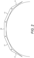
- each outer column 11 there is one outer column 11 either side of the central column 10 as shown in Fig. 1 , but it is possible and may enhance performance if there are two outer columns 11 on each side of central column 10 - i.e., a total of 5 segments as shown in Fig.2 .
- the length of each segment is around 50 mm. This may be dictated by the compliance of the sensor strip and leg geometry and might be as low as 10 mm. 50-60 mm is often the largest practical size.
- Figure 3 shows how the sensor strip geometry works. For clarity, only one outer column 11 is shown to the right of the central column 10, as opposed to a sensor strip construction in accordance with the present invention where there is an outer column either side.
- the drawing shows in addition a mandrel 13 and a bandage 14.
- the pressure exerted on the flat upper surface of the sensor's central column 10 will be the same as if the sensor strip was not there (other than a small change of a few percent due to the fact that the sensor thickness of typically 3 mm adds to the effective radius of the leg which might be 35 mm or more), if the bandage leaves the edge of the central column 10 at the correct angle ⁇ , where this angle is the angle of the tangent to the curvature of the bandage shown by the bold curved line.
- the pivot and segmentation need to ensure the bandage follows to within a certain accuracy the same path as it would if the sensor strip was a continuous (unsegmented) flexible layer, as opposed to rigid segments joined together. It can be shown geometrically and theoretically that as long as the gap between segments is small ( ⁇ 1 mm) and the column width is ⁇ 15mm that the error in pressure is ⁇ 10%. Similar considerations apply to the design of a one-piece segmented structure.
- the segmentation allows the use of a relatively rigid material to form the sensor strip of a only a few mm in thickness, which enables cost-effective mass manufacturable sensor strips.
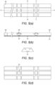
- Fig. 5(a) shows a sensor strip of the present invention formed by mounting a rubber strip 20 on a flexible PCB substrate 21.
- Fig. 5(b) is a section A-A along Fig. 5(a) , which shows in more detail a connector 26, optical proximity sensors 22, each formed in cavity 23, with an (optional) stiffener 24 and reflectors 25.
- Fig. 5(c) is a section along B-B in Fig. 5(a) . The position of each cavity 23 is illustrated in Fig. 5(d) .
- the upper surface of the rubber strip 20 is textured, or a layer of a suitable material is laid on top, in order to enhance contact reproducibility.
- a sensor strip of the present invention comprises a one-piece rubber strip or similar structure with a grooved surface to provide the segmentation, below which is attached a flexible PCB to route the signals to the electrical connector and to mount the optical proximity detectors.
- Fig. 5(b) shows the flexible PCB 21 running the length of the sensor strip.
- the sensor cavity 23 is a recess, preferably a circular recess, formed in the rubber strip 20, the internal top surface of which may be coated with suitable reflective material 25, preferably a diffuse Lambertian reflector such as a suitable white paint printed onto the rubber.
- each sensor cavity is shown as square, but circular is an option.
- a square may be used as it presents a uniform edge for the bandage to land on, given the curved geometry the sensor strip is designed to be used on e.g., a human leg.
- the contact area with the bandage should be constant and preferably as close to 100% of the apparent contact area as possible.
- Black, Closed-cell, Firm Grade Neoprene Foam is a suitable material.
- the spring constant of the sensor strip and therefore the full-scale excursion of the sensor strip is determined largely by the Youngs Modulus of the rubber foam (HT800), but depends on the area of the recess 23.
- voids could be moulded into the rubber around the sensor cavity to further reduce the area of rubber between the top and bottom of the sensor strip and hence the effective Youngs Modulus of the rubber.
- Another feature is that low-cost phototransistors may be used in the design. However, they have a significant temperature drift which adversely affects the accuracy of the sensors. This can be mitigated by providing an extra proximity detector either next to each sensor or in the centre of the strip, which is set in a cavity that does not respond to pressure. Thus, it will only respond to temperature and this reading can be used to null out any temperature drift. It might be thought that an extra proximity sensor needs to be provided for each sensor but as the sensor will be used under a bandage it is likely it will be at a uniform temperature and so only one compensation device needs to be provided.
- the flexible PCB substrate 21 contains the proximity sensors 22 which preferably comprise an LED mounted next to a phototransistor, as is well known to produce a proximity detector. Over a distance of about 1 mm the divergence of the light from the LED ensures that the amount reflected back to the phototransistor varies with distance.
- the LED and phototransistor are both mounted on the flexible PCB substrate 21 so that the optical axes are parallel and about 1 mm apart, with a barrier to prevent cross talk.
- a standard technique to eliminate this effect further is used in that the LED is pulsed on and off (at about 1 KHz).
- the readings from the phototransistor are taken at LED OFF and LED ON states and this allows subtraction of any offset due to ambient light.
- the preferred pulsing at 1 KHz also avoids effects due to noise pickup which tends to be at mains frequency of 50 Hz.
- the electrical connector of the sensor strip can be coupled to a separate interrogator unit (not shown), typically a small electronics box which could be belt worn by a patient.
- the interrogator unit houses electronics that are configured to pulse the LEDs and receive the signals from the phototransistors and amplify them using transimpedance amplifiers.
- the amplifiers are preferably rolled off at about 50 KHz as this allows enough bandwidth whilst keeping noise relatively low.
- the signal for LED ON and LED OFF is sampled by a microcontroller, but a delay is introduced so the signal can settle before it is sampled. This avoids any effects due to bandwidth limitations affecting the signal. Typically, 100-1000 samples are taken and then averaged to derive a reading.
- the individual sensors are generally calibrated hydrostatically, as this avoids contact area issues and is considered a gold standard for pressure calibration.
- a sensor typically will have a transfer function of output voltage vs pressure and this function is linear with both an offset due to manufacturing tolerances and a quadratic term due to the non-linearity of the proximity detector transfer function.
- the calibration data in the form of the terms a,b,c in the polynomial ax 2 + bx + c are stored in a non-volatile memory chip (not shown) integrated on the flexible PCB strip. These data are then read by the microcontroller in the interrogation unit and used to calculate an actual pressure reading from the signals from the individual sensors. A temperature correction can also be applied.
- the individual sensors are not expected to drift excessively during storage and therefore if the voltage at zero pressure is different from the value at calibration (which can also be stored on the memory chip) by too great a margin the sensor will be flagged as faulty.
- the interrogator unit is configured to measure the current drawn by the LEDs and if this is different will be flagged as an error. It would be possible to pinpoint the current change associated with one sensor on the sensor strip failing and to continue using the others (typically 5) on the sensor strip.
- Other data are stored on the memory chip for each sensor such as batch number, date of manufacture, date of calibration, number of uses or whether first time use or not (for single use sensors).
- the interrogator unit provided is able to communicate recorded measurements via a USB interface to PC, tablet etc, or to a Bluetooth-enabled device for display on a graphical user interface (GUI).
- GUI graphical user interface
- a typical user interface is a histogram type display showing the pressure graded up the leg.
Landscapes
- Health & Medical Sciences (AREA)
- Life Sciences & Earth Sciences (AREA)
- Engineering & Computer Science (AREA)
- Biomedical Technology (AREA)
- Heart & Thoracic Surgery (AREA)
- Animal Behavior & Ethology (AREA)
- General Health & Medical Sciences (AREA)
- Public Health (AREA)
- Veterinary Medicine (AREA)
- Vascular Medicine (AREA)
- Medical Informatics (AREA)
- Physics & Mathematics (AREA)
- Biophysics (AREA)
- Pathology (AREA)
- Molecular Biology (AREA)
- Surgery (AREA)
- Oral & Maxillofacial Surgery (AREA)
- Dentistry (AREA)
- Epidemiology (AREA)
- Force Measurement Appropriate To Specific Purposes (AREA)
- Measuring Fluid Pressure (AREA)
- Measuring And Recording Apparatus For Diagnosis (AREA)
Claims (11)
- Sensorstreifen, umfassend ein längliches Element, welches segmentiert ist, wobei die Segmente (12) durch fortlaufende Längs- und Querrillen definiert sind, sodass benachbarte Segmente (12) aneinander angelenkt sind, wobei die Längsrillen eine zentrale Säule (20) von Segmenten (12) und äußere Säulen (11) von Segmenten definieren, wobei die Segmente (12) in den äußersten Säulen (11) nach außen abgeschrägt sind, und dadurch gekennzeichnet, dass ein druckempfindlicher Sensor in einer Vielzahl von Segmenten (12) in der zentralen Säule (11) montiert ist.
- Sensorstreifen nach Anspruch 1, welcher zumindest 3 druckempfindliche Sensoren umfasst.
- Sensorstreifen nach Anspruch 1 oder Anspruch 2, welcher bis zu 6 druckempfindliche Sensoren umfasst.
- Sensorstreifen nach einem vorstehenden Anspruch, wobei die druckempfindlichen Sensoren in nicht benachbarten Segmenten (12) montiert sind.
- Sensorstreifen nach einem vorstehenden Anspruch, welcher zumindest 2 äußere Säulen (11) zu beiden Seiten der zentralen Säule (20) umfasst.
- Sensorstreifen nach einem vorstehenden Anspruch, welcher zusätzlich einen nicht druckempfindlichen Referenzsensor umfasst.
- Sensorstreifen nach einem vorstehenden Anspruch, wobei die Basis jedes Segments (12), in welchem ein druckempfindlicher Sensor montiert ist, starr ist.
- Sensorstreifen nach einem vorstehenden Anspruch, wobei jedes der Segmente (12) aus einem starren Material gebildet ist.
- Sensorstreifen nach einem vorstehenden Anspruch, in welchem die Segmente (12) aus einem Gummimaterial, bevorzugt einem NEOPRENE-Schaumstoff, und bevorzugter einem anliegenden Blatt von segmentiertem Material gebildet sind.
- Sensorstreifen nach einem vorstehenden Anspruch, weiter einen elektrischen Steckverbinder (26) umfassend, um Datensignale aus den druckempfindlichen Sensoren mit einer entfernt gekoppelten Abfrageeinheit zur Datenverarbeitung zu koppeln.
- Verfahren zum Testen des Drucks unter einem Verband (14), welches Einführen eines Sensorstreifen nach einem vorstehenden Anspruch unter den Verband (14) und Aufzeichnen des Drucks an jedem der druckempfindlichen Sensoren umfasst.
Applications Claiming Priority (2)
| Application Number | Priority Date | Filing Date | Title |
|---|---|---|---|
| GBGB2010588.8A GB202010588D0 (en) | 2020-07-09 | 2020-07-09 | Sensor |
| PCT/GB2021/051762 WO2022008927A1 (en) | 2020-07-09 | 2021-07-09 | Pressure sensor strip |
Publications (3)
| Publication Number | Publication Date |
|---|---|
| EP4178510A1 EP4178510A1 (de) | 2023-05-17 |
| EP4178510C0 EP4178510C0 (de) | 2024-08-28 |
| EP4178510B1 true EP4178510B1 (de) | 2024-08-28 |
Family
ID=72139904
Family Applications (1)
| Application Number | Title | Priority Date | Filing Date |
|---|---|---|---|
| EP21749246.1A Active EP4178510B1 (de) | 2020-07-09 | 2021-07-09 | Drucksensorleiste |
Country Status (11)
| Country | Link |
|---|---|
| US (1) | US20230255837A1 (de) |
| EP (1) | EP4178510B1 (de) |
| KR (1) | KR20230061340A (de) |
| AU (1) | AU2021304438A1 (de) |
| BR (1) | BR112023000376A2 (de) |
| CA (1) | CA3184977A1 (de) |
| ES (1) | ES2992742T3 (de) |
| GB (1) | GB202010588D0 (de) |
| MX (1) | MX2023000471A (de) |
| PL (1) | PL4178510T3 (de) |
| WO (1) | WO2022008927A1 (de) |
Families Citing this family (1)
| Publication number | Priority date | Publication date | Assignee | Title |
|---|---|---|---|---|
| TWI839883B (zh) * | 2022-10-06 | 2024-04-21 | 達運精密工業股份有限公司 | 非接觸式開關及其控制系統 |
Family Cites Families (14)
| Publication number | Priority date | Publication date | Assignee | Title |
|---|---|---|---|---|
| US5253654A (en) * | 1992-04-30 | 1993-10-19 | Thomas Berten R | Orthopedic weight monitor |
| US5494043A (en) * | 1993-05-04 | 1996-02-27 | Vital Insite, Inc. | Arterial sensor |
| WO2006030405A1 (en) * | 2004-09-14 | 2006-03-23 | University Of Limerick | A transducer apparatus for measuring biomedical pressures |
| GB0506308D0 (en) * | 2005-03-29 | 2005-05-04 | Taylor Michael | Bandage pressure monitor |
| JP5198608B2 (ja) * | 2010-03-18 | 2013-05-15 | 韓国標準科学研究院 | 半導体ストレインゲージを用いたフレキシブルな力または圧力センサアレイ、そのフレキシブルな力または圧力センサアレイの製造方法、及びそのフレキシブルな力または圧力センサアレイを用いた力または圧力測定方法 |
| US20140371566A1 (en) * | 2013-06-14 | 2014-12-18 | Cardiothrive, Inc. | Conforming patient contact interface and method for using same |
| US20170079868A1 (en) * | 2013-12-06 | 2017-03-23 | Lawrence G. Reid, Jr. | Compression and Sensing System and Method |
| US10034622B1 (en) * | 2014-10-15 | 2018-07-31 | Fadi A. Mahmoud | In-shoe foot monitoring utilizing an insert |
| US10532217B2 (en) * | 2015-09-30 | 2020-01-14 | Zoll Medical Corporation | Medical device operational modes |
| EP3439598B1 (de) | 2016-04-05 | 2021-09-08 | VeinSense Ltd | Drucksensor |
| US11920996B2 (en) * | 2018-03-09 | 2024-03-05 | Case Western Reserve University | Customizable pressure sensor array |
| US20190358106A1 (en) * | 2018-05-24 | 2019-11-28 | Cynthia Barney | Method and apparatus for improved physical rehabilitation of patients with impaired mobility |
| ES3036095T3 (en) * | 2018-12-20 | 2025-09-12 | Univ Of Galway | A pressure sensing device for use with a compression bandage |
| CN113739961A (zh) * | 2020-05-28 | 2021-12-03 | 纳米及先进材料研发院有限公司 | 柔性压力传感器阵列及其制造方法 |
-
2020
- 2020-07-09 GB GBGB2010588.8A patent/GB202010588D0/en not_active Ceased
-
2021
- 2021-07-09 AU AU2021304438A patent/AU2021304438A1/en active Pending
- 2021-07-09 ES ES21749246T patent/ES2992742T3/es active Active
- 2021-07-09 CA CA3184977A patent/CA3184977A1/en active Pending
- 2021-07-09 PL PL21749246.1T patent/PL4178510T3/pl unknown
- 2021-07-09 WO PCT/GB2021/051762 patent/WO2022008927A1/en not_active Ceased
- 2021-07-09 MX MX2023000471A patent/MX2023000471A/es unknown
- 2021-07-09 KR KR1020237004265A patent/KR20230061340A/ko not_active Withdrawn
- 2021-07-09 US US18/015,123 patent/US20230255837A1/en active Pending
- 2021-07-09 EP EP21749246.1A patent/EP4178510B1/de active Active
- 2021-07-09 BR BR112023000376A patent/BR112023000376A2/pt not_active Application Discontinuation
Also Published As
| Publication number | Publication date |
|---|---|
| MX2023000471A (es) | 2023-04-20 |
| KR20230061340A (ko) | 2023-05-08 |
| WO2022008927A1 (en) | 2022-01-13 |
| AU2021304438A1 (en) | 2023-03-09 |
| EP4178510C0 (de) | 2024-08-28 |
| GB202010588D0 (en) | 2020-08-26 |
| PL4178510T3 (pl) | 2025-01-07 |
| US20230255837A1 (en) | 2023-08-17 |
| BR112023000376A2 (pt) | 2023-01-31 |
| CA3184977A1 (en) | 2022-01-13 |
| EP4178510A1 (de) | 2023-05-17 |
| ES2992742T3 (en) | 2024-12-17 |
Similar Documents
| Publication | Publication Date | Title |
|---|---|---|
| ES2651674T3 (es) | Sensor de dilatación FBG para superficies curvadas | |
| EP4178510B1 (de) | Drucksensorleiste | |
| ES2533328T3 (es) | Sensor de presión | |
| US10888464B2 (en) | Pressure sensor for measuring pressure applied by a bandage or stocking | |
| EP3453320B1 (de) | Pulswellendetektionsvorrichtung und vorrichtung zur messung biologischer informationen | |
| EP0059539B2 (de) | Druckfühler | |
| WO2006030405A1 (en) | A transducer apparatus for measuring biomedical pressures | |
| FR2614988A1 (fr) | Capteur capacitif de pression | |
| US20210131898A1 (en) | Temperature compensation of strain gauge output | |
| US9194991B2 (en) | Fiber optic sensor manufacturing method and structure thereof | |
| KR102061614B1 (ko) | 능동형 피부 접촉 센서 | |
| US20240418587A1 (en) | A sensor | |
| CN115684089B (zh) | 光纤湿度传感器及形成方法 | |
| US20250314538A1 (en) | High-resistance sensor and method for using same | |
| US11530959B2 (en) | Pressure sensing element and pressure sensor having a diaphragm that includes a trench and a plurality of beams | |
| JP3731183B2 (ja) | 接触圧血流センサ | |
| JP7753210B2 (ja) | 感圧装置 | |
| JP2007301232A (ja) | 圧脈波センサおよびこれを備えた脈波測定装置 | |
| RU2115897C1 (ru) | Интегральный преобразователь деформации и температуры | |
| IE84492B1 (en) | A transducer apparatus for measuring biomedical pressures | |
| TW202002308A (zh) | 壓力感測器 | |
| IE20050606A1 (en) | A transducer apparatus for measuring biomedical pressures | |
| US20210156774A1 (en) | Elasticity measurement device | |
| KR20250166970A (ko) | 인체 자체 정전용량 간섭을 제거할 수 있는 피부 성분 측정 모듈 | |
| KR101921379B1 (ko) | 밴딩 측정이 가능한 온도센서 |
Legal Events
| Date | Code | Title | Description |
|---|---|---|---|
| STAA | Information on the status of an ep patent application or granted ep patent |
Free format text: STATUS: UNKNOWN |
|
| STAA | Information on the status of an ep patent application or granted ep patent |
Free format text: STATUS: THE INTERNATIONAL PUBLICATION HAS BEEN MADE |
|
| PUAI | Public reference made under article 153(3) epc to a published international application that has entered the european phase |
Free format text: ORIGINAL CODE: 0009012 |
|
| STAA | Information on the status of an ep patent application or granted ep patent |
Free format text: STATUS: REQUEST FOR EXAMINATION WAS MADE |
|
| 17P | Request for examination filed |
Effective date: 20230124 |
|
| AK | Designated contracting states |
Kind code of ref document: A1 Designated state(s): AL AT BE BG CH CY CZ DE DK EE ES FI FR GB GR HR HU IE IS IT LI LT LU LV MC MK MT NL NO PL PT RO RS SE SI SK SM TR |
|
| DAV | Request for validation of the european patent (deleted) | ||
| DAX | Request for extension of the european patent (deleted) | ||
| GRAP | Despatch of communication of intention to grant a patent |
Free format text: ORIGINAL CODE: EPIDOSNIGR1 |
|
| STAA | Information on the status of an ep patent application or granted ep patent |
Free format text: STATUS: GRANT OF PATENT IS INTENDED |
|
| INTG | Intention to grant announced |
Effective date: 20240301 |
|
| GRAS | Grant fee paid |
Free format text: ORIGINAL CODE: EPIDOSNIGR3 |
|
| GRAA | (expected) grant |
Free format text: ORIGINAL CODE: 0009210 |
|
| STAA | Information on the status of an ep patent application or granted ep patent |
Free format text: STATUS: THE PATENT HAS BEEN GRANTED |
|
| AK | Designated contracting states |
Kind code of ref document: B1 Designated state(s): AL AT BE BG CH CY CZ DE DK EE ES FI FR GB GR HR HU IE IS IT LI LT LU LV MC MK MT NL NO PL PT RO RS SE SI SK SM TR |
|
| REG | Reference to a national code |
Ref country code: CH Ref legal event code: EP |
|
| REG | Reference to a national code |
Ref country code: DE Ref legal event code: R096 Ref document number: 602021017987 Country of ref document: DE |
|
| REG | Reference to a national code |
Ref country code: IE Ref legal event code: FG4D |
|
| U01 | Request for unitary effect filed |
Effective date: 20240925 |
|
| U07 | Unitary effect registered |
Designated state(s): AT BE BG DE DK EE FI FR IT LT LU LV MT NL PT RO SE SI Effective date: 20241022 |
|
| REG | Reference to a national code |
Ref country code: ES Ref legal event code: FG2A Ref document number: 2992742 Country of ref document: ES Kind code of ref document: T3 Effective date: 20241217 |
|
| PG25 | Lapsed in a contracting state [announced via postgrant information from national office to epo] |
Ref country code: NO Free format text: LAPSE BECAUSE OF FAILURE TO SUBMIT A TRANSLATION OF THE DESCRIPTION OR TO PAY THE FEE WITHIN THE PRESCRIBED TIME-LIMIT Effective date: 20241128 |
|
| PG25 | Lapsed in a contracting state [announced via postgrant information from national office to epo] |
Ref country code: GR Free format text: LAPSE BECAUSE OF FAILURE TO SUBMIT A TRANSLATION OF THE DESCRIPTION OR TO PAY THE FEE WITHIN THE PRESCRIBED TIME-LIMIT Effective date: 20241129 |
|
| PG25 | Lapsed in a contracting state [announced via postgrant information from national office to epo] |
Ref country code: IS Free format text: LAPSE BECAUSE OF FAILURE TO SUBMIT A TRANSLATION OF THE DESCRIPTION OR TO PAY THE FEE WITHIN THE PRESCRIBED TIME-LIMIT Effective date: 20241228 |
|
| PG25 | Lapsed in a contracting state [announced via postgrant information from national office to epo] |
Ref country code: HR Free format text: LAPSE BECAUSE OF FAILURE TO SUBMIT A TRANSLATION OF THE DESCRIPTION OR TO PAY THE FEE WITHIN THE PRESCRIBED TIME-LIMIT Effective date: 20240828 |
|
| PG25 | Lapsed in a contracting state [announced via postgrant information from national office to epo] |
Ref country code: RS Free format text: LAPSE BECAUSE OF FAILURE TO SUBMIT A TRANSLATION OF THE DESCRIPTION OR TO PAY THE FEE WITHIN THE PRESCRIBED TIME-LIMIT Effective date: 20241128 |
|
| PG25 | Lapsed in a contracting state [announced via postgrant information from national office to epo] |
Ref country code: RS Free format text: LAPSE BECAUSE OF FAILURE TO SUBMIT A TRANSLATION OF THE DESCRIPTION OR TO PAY THE FEE WITHIN THE PRESCRIBED TIME-LIMIT Effective date: 20241128 Ref country code: NO Free format text: LAPSE BECAUSE OF FAILURE TO SUBMIT A TRANSLATION OF THE DESCRIPTION OR TO PAY THE FEE WITHIN THE PRESCRIBED TIME-LIMIT Effective date: 20241128 Ref country code: IS Free format text: LAPSE BECAUSE OF FAILURE TO SUBMIT A TRANSLATION OF THE DESCRIPTION OR TO PAY THE FEE WITHIN THE PRESCRIBED TIME-LIMIT Effective date: 20241228 Ref country code: HR Free format text: LAPSE BECAUSE OF FAILURE TO SUBMIT A TRANSLATION OF THE DESCRIPTION OR TO PAY THE FEE WITHIN THE PRESCRIBED TIME-LIMIT Effective date: 20240828 Ref country code: GR Free format text: LAPSE BECAUSE OF FAILURE TO SUBMIT A TRANSLATION OF THE DESCRIPTION OR TO PAY THE FEE WITHIN THE PRESCRIBED TIME-LIMIT Effective date: 20241129 |
|
| PG25 | Lapsed in a contracting state [announced via postgrant information from national office to epo] |
Ref country code: SM Free format text: LAPSE BECAUSE OF FAILURE TO SUBMIT A TRANSLATION OF THE DESCRIPTION OR TO PAY THE FEE WITHIN THE PRESCRIBED TIME-LIMIT Effective date: 20240828 |
|
| PG25 | Lapsed in a contracting state [announced via postgrant information from national office to epo] |
Ref country code: CZ Free format text: LAPSE BECAUSE OF FAILURE TO SUBMIT A TRANSLATION OF THE DESCRIPTION OR TO PAY THE FEE WITHIN THE PRESCRIBED TIME-LIMIT Effective date: 20240828 |
|
| PG25 | Lapsed in a contracting state [announced via postgrant information from national office to epo] |
Ref country code: SK Free format text: LAPSE BECAUSE OF FAILURE TO SUBMIT A TRANSLATION OF THE DESCRIPTION OR TO PAY THE FEE WITHIN THE PRESCRIBED TIME-LIMIT Effective date: 20240828 |
|
| PLBE | No opposition filed within time limit |
Free format text: ORIGINAL CODE: 0009261 |
|
| STAA | Information on the status of an ep patent application or granted ep patent |
Free format text: STATUS: NO OPPOSITION FILED WITHIN TIME LIMIT |
|
| 26N | No opposition filed |
Effective date: 20250530 |
|
| U20 | Renewal fee for the european patent with unitary effect paid |
Year of fee payment: 5 Effective date: 20250708 |
|
| PGFP | Annual fee paid to national office [announced via postgrant information from national office to epo] |
Ref country code: PL Payment date: 20250709 Year of fee payment: 5 Ref country code: TR Payment date: 20250708 Year of fee payment: 5 |
|
| PGFP | Annual fee paid to national office [announced via postgrant information from national office to epo] |
Ref country code: GB Payment date: 20250708 Year of fee payment: 5 |
|
| PGFP | Annual fee paid to national office [announced via postgrant information from national office to epo] |
Ref country code: CH Payment date: 20250801 Year of fee payment: 5 |
|
| PGFP | Annual fee paid to national office [announced via postgrant information from national office to epo] |
Ref country code: IE Payment date: 20250708 Year of fee payment: 5 |