EP4177991A1 - Bipolarplatte für eine brennstoffzelle mit integrierter leiteranordnung zur erzeugung eines gerichteten elektromagnetischen feldes - Google Patents
Bipolarplatte für eine brennstoffzelle mit integrierter leiteranordnung zur erzeugung eines gerichteten elektromagnetischen feldes Download PDFInfo
- Publication number
- EP4177991A1 EP4177991A1 EP21207287.0A EP21207287A EP4177991A1 EP 4177991 A1 EP4177991 A1 EP 4177991A1 EP 21207287 A EP21207287 A EP 21207287A EP 4177991 A1 EP4177991 A1 EP 4177991A1
- Authority
- EP
- European Patent Office
- Prior art keywords
- bipolar plate
- fuel cell
- electrical conductor
- flow channel
- gas flow
- Prior art date
- Legal status (The legal status is an assumption and is not a legal conclusion. Google has not performed a legal analysis and makes no representation as to the accuracy of the status listed.)
- Granted
Links
Images



Classifications
-
- H—ELECTRICITY
- H01—ELECTRIC ELEMENTS
- H01M—PROCESSES OR MEANS, e.g. BATTERIES, FOR THE DIRECT CONVERSION OF CHEMICAL ENERGY INTO ELECTRICAL ENERGY
- H01M8/00—Fuel cells; Manufacture thereof
- H01M8/02—Details
- H01M8/0202—Collectors; Separators, e.g. bipolar separators; Interconnectors
- H01M8/0204—Non-porous and characterised by the material
- H01M8/0215—Glass; Ceramic materials
-
- H—ELECTRICITY
- H01—ELECTRIC ELEMENTS
- H01M—PROCESSES OR MEANS, e.g. BATTERIES, FOR THE DIRECT CONVERSION OF CHEMICAL ENERGY INTO ELECTRICAL ENERGY
- H01M8/00—Fuel cells; Manufacture thereof
- H01M8/04—Auxiliary arrangements, e.g. for control of pressure or for circulation of fluids
- H01M8/04082—Arrangements for control of reactant parameters, e.g. pressure or concentration
- H01M8/04089—Arrangements for control of reactant parameters, e.g. pressure or concentration of gaseous reactants
-
- H—ELECTRICITY
- H01—ELECTRIC ELEMENTS
- H01M—PROCESSES OR MEANS, e.g. BATTERIES, FOR THE DIRECT CONVERSION OF CHEMICAL ENERGY INTO ELECTRICAL ENERGY
- H01M8/00—Fuel cells; Manufacture thereof
- H01M8/02—Details
- H01M8/0202—Collectors; Separators, e.g. bipolar separators; Interconnectors
- H01M8/0258—Collectors; Separators, e.g. bipolar separators; Interconnectors characterised by the configuration of channels, e.g. by the flow field of the reactant or coolant
-
- B—PERFORMING OPERATIONS; TRANSPORTING
- B33—ADDITIVE MANUFACTURING TECHNOLOGY
- B33Y—ADDITIVE MANUFACTURING, i.e. MANUFACTURING OF THREE-DIMENSIONAL [3D] OBJECTS BY ADDITIVE DEPOSITION, ADDITIVE AGGLOMERATION OR ADDITIVE LAYERING, e.g. BY 3D PRINTING, STEREOLITHOGRAPHY OR SELECTIVE LASER SINTERING
- B33Y80/00—Products made by additive manufacturing
-
- H—ELECTRICITY
- H01—ELECTRIC ELEMENTS
- H01B—CABLES; CONDUCTORS; INSULATORS; SELECTION OF MATERIALS FOR THEIR CONDUCTIVE, INSULATING OR DIELECTRIC PROPERTIES
- H01B12/00—Superconductive or hyperconductive conductors, cables, or transmission lines
- H01B12/16—Superconductive or hyperconductive conductors, cables, or transmission lines characterised by cooling
-
- H—ELECTRICITY
- H01—ELECTRIC ELEMENTS
- H01M—PROCESSES OR MEANS, e.g. BATTERIES, FOR THE DIRECT CONVERSION OF CHEMICAL ENERGY INTO ELECTRICAL ENERGY
- H01M4/00—Electrodes
- H01M4/86—Inert electrodes with catalytic activity, e.g. for fuel cells
- H01M4/8605—Porous electrodes
- H01M4/8621—Porous electrodes containing only metallic or ceramic material, e.g. made by sintering or sputtering
-
- H—ELECTRICITY
- H01—ELECTRIC ELEMENTS
- H01M—PROCESSES OR MEANS, e.g. BATTERIES, FOR THE DIRECT CONVERSION OF CHEMICAL ENERGY INTO ELECTRICAL ENERGY
- H01M4/00—Electrodes
- H01M4/86—Inert electrodes with catalytic activity, e.g. for fuel cells
- H01M4/8605—Porous electrodes
- H01M4/8626—Porous electrodes characterised by the form
- H01M4/8631—Bipolar electrodes
-
- H—ELECTRICITY
- H01—ELECTRIC ELEMENTS
- H01M—PROCESSES OR MEANS, e.g. BATTERIES, FOR THE DIRECT CONVERSION OF CHEMICAL ENERGY INTO ELECTRICAL ENERGY
- H01M8/00—Fuel cells; Manufacture thereof
- H01M8/02—Details
- H01M8/0202—Collectors; Separators, e.g. bipolar separators; Interconnectors
-
- H—ELECTRICITY
- H01—ELECTRIC ELEMENTS
- H01M—PROCESSES OR MEANS, e.g. BATTERIES, FOR THE DIRECT CONVERSION OF CHEMICAL ENERGY INTO ELECTRICAL ENERGY
- H01M8/00—Fuel cells; Manufacture thereof
- H01M8/02—Details
- H01M8/0202—Collectors; Separators, e.g. bipolar separators; Interconnectors
- H01M8/0204—Non-porous and characterised by the material
- H01M8/0213—Gas-impermeable carbon-containing materials
-
- H—ELECTRICITY
- H01—ELECTRIC ELEMENTS
- H01M—PROCESSES OR MEANS, e.g. BATTERIES, FOR THE DIRECT CONVERSION OF CHEMICAL ENERGY INTO ELECTRICAL ENERGY
- H01M8/00—Fuel cells; Manufacture thereof
- H01M8/02—Details
- H01M8/0297—Arrangements for joining electrodes, reservoir layers, heat exchange units or bipolar separators to each other
-
- H—ELECTRICITY
- H01—ELECTRIC ELEMENTS
- H01M—PROCESSES OR MEANS, e.g. BATTERIES, FOR THE DIRECT CONVERSION OF CHEMICAL ENERGY INTO ELECTRICAL ENERGY
- H01M8/00—Fuel cells; Manufacture thereof
- H01M8/04—Auxiliary arrangements, e.g. for control of pressure or for circulation of fluids
- H01M8/04007—Auxiliary arrangements, e.g. for control of pressure or for circulation of fluids related to heat exchange
-
- H—ELECTRICITY
- H01—ELECTRIC ELEMENTS
- H01M—PROCESSES OR MEANS, e.g. BATTERIES, FOR THE DIRECT CONVERSION OF CHEMICAL ENERGY INTO ELECTRICAL ENERGY
- H01M8/00—Fuel cells; Manufacture thereof
- H01M8/04—Auxiliary arrangements, e.g. for control of pressure or for circulation of fluids
- H01M8/04007—Auxiliary arrangements, e.g. for control of pressure or for circulation of fluids related to heat exchange
- H01M8/04014—Heat exchange using gaseous fluids; Heat exchange by combustion of reactants
-
- H—ELECTRICITY
- H01—ELECTRIC ELEMENTS
- H01M—PROCESSES OR MEANS, e.g. BATTERIES, FOR THE DIRECT CONVERSION OF CHEMICAL ENERGY INTO ELECTRICAL ENERGY
- H01M8/00—Fuel cells; Manufacture thereof
- H01M8/04—Auxiliary arrangements, e.g. for control of pressure or for circulation of fluids
- H01M8/04082—Arrangements for control of reactant parameters, e.g. pressure or concentration
- H01M8/04201—Reactant storage and supply, e.g. means for feeding, pipes
-
- H—ELECTRICITY
- H01—ELECTRIC ELEMENTS
- H01M—PROCESSES OR MEANS, e.g. BATTERIES, FOR THE DIRECT CONVERSION OF CHEMICAL ENERGY INTO ELECTRICAL ENERGY
- H01M8/00—Fuel cells; Manufacture thereof
- H01M8/04—Auxiliary arrangements, e.g. for control of pressure or for circulation of fluids
- H01M8/04223—Auxiliary arrangements, e.g. for control of pressure or for circulation of fluids during start-up or shut-down; Depolarisation or activation, e.g. purging; Means for short-circuiting defective fuel cells
-
- H—ELECTRICITY
- H01—ELECTRIC ELEMENTS
- H01M—PROCESSES OR MEANS, e.g. BATTERIES, FOR THE DIRECT CONVERSION OF CHEMICAL ENERGY INTO ELECTRICAL ENERGY
- H01M8/00—Fuel cells; Manufacture thereof
- H01M8/04—Auxiliary arrangements, e.g. for control of pressure or for circulation of fluids
- H01M8/04298—Processes for controlling fuel cells or fuel cell systems
- H01M8/04694—Processes for controlling fuel cells or fuel cell systems characterised by variables to be controlled
- H01M8/04746—Pressure; Flow
- H01M8/04753—Pressure; Flow of fuel cell reactants
-
- H—ELECTRICITY
- H01—ELECTRIC ELEMENTS
- H01M—PROCESSES OR MEANS, e.g. BATTERIES, FOR THE DIRECT CONVERSION OF CHEMICAL ENERGY INTO ELECTRICAL ENERGY
- H01M8/00—Fuel cells; Manufacture thereof
- H01M8/24—Grouping of fuel cells, e.g. stacking of fuel cells
- H01M8/2457—Grouping of fuel cells, e.g. stacking of fuel cells with both reactants being gaseous or vaporised
-
- H—ELECTRICITY
- H01—ELECTRIC ELEMENTS
- H01M—PROCESSES OR MEANS, e.g. BATTERIES, FOR THE DIRECT CONVERSION OF CHEMICAL ENERGY INTO ELECTRICAL ENERGY
- H01M8/00—Fuel cells; Manufacture thereof
- H01M8/24—Grouping of fuel cells, e.g. stacking of fuel cells
- H01M8/2465—Details of groupings of fuel cells
-
- B—PERFORMING OPERATIONS; TRANSPORTING
- B29—WORKING OF PLASTICS; WORKING OF SUBSTANCES IN A PLASTIC STATE IN GENERAL
- B29C—SHAPING OR JOINING OF PLASTICS; SHAPING OF MATERIAL IN A PLASTIC STATE, NOT OTHERWISE PROVIDED FOR; AFTER-TREATMENT OF THE SHAPED PRODUCTS, e.g. REPAIRING
- B29C64/00—Additive manufacturing, i.e. manufacturing of three-dimensional [3D] objects by additive deposition, additive agglomeration or additive layering, e.g. by 3D printing, stereolithography or selective laser sintering
- B29C64/10—Processes of additive manufacturing
-
- H—ELECTRICITY
- H01—ELECTRIC ELEMENTS
- H01M—PROCESSES OR MEANS, e.g. BATTERIES, FOR THE DIRECT CONVERSION OF CHEMICAL ENERGY INTO ELECTRICAL ENERGY
- H01M4/00—Electrodes
- H01M4/86—Inert electrodes with catalytic activity, e.g. for fuel cells
- H01M2004/8678—Inert electrodes with catalytic activity, e.g. for fuel cells characterised by the polarity
- H01M2004/8694—Bipolar electrodes
-
- Y—GENERAL TAGGING OF NEW TECHNOLOGICAL DEVELOPMENTS; GENERAL TAGGING OF CROSS-SECTIONAL TECHNOLOGIES SPANNING OVER SEVERAL SECTIONS OF THE IPC; TECHNICAL SUBJECTS COVERED BY FORMER USPC CROSS-REFERENCE ART COLLECTIONS [XRACs] AND DIGESTS
- Y02—TECHNOLOGIES OR APPLICATIONS FOR MITIGATION OR ADAPTATION AGAINST CLIMATE CHANGE
- Y02E—REDUCTION OF GREENHOUSE GAS [GHG] EMISSIONS, RELATED TO ENERGY GENERATION, TRANSMISSION OR DISTRIBUTION
- Y02E60/00—Enabling technologies; Technologies with a potential or indirect contribution to GHG emissions mitigation
- Y02E60/30—Hydrogen technology
- Y02E60/50—Fuel cells
Definitions
- the present description relates to a bipolar plate for a fuel cell for generating electricity.
- the present description relates to a fuel cell, a fuel cell stack, an in particular additive manufacturing method for producing a bipolar plate, a method for operating a fuel cell and an aircraft having a fuel cell.
- a fuel cell also called a galvanic cell, converts the chemical reaction energy of a continuously supplied fuel, usually hydrogen as a reactant, and an oxidizing agent into electrical energy.
- fuel cells have bipolar plates as electrodes with a milled gas flow channel structure for defined conduction of the reactant.
- the flow of a reactant from the gas channels into a bipolar plate is dependent on the pressure in the gas flow channel, the cross-sectional shape of the gas flow channel, and the area exposed to the electrode.
- the gas flow can be varied, for example by varying the pressure of the hydrogen gas on the anode side.
- the air can be replaced to varying degrees by pure oxygen on the cathode side.
- the fast response behavior of a fuel cell is of great importance for aviation applications, for example when a restart is necessary shortly before touchdown, and has been the subject of research for many years.
- a bipolar plate for a fuel cell for generating electrical current has a bipolar plate body with a first surface, the bipolar plate body being set up to be in contact with an electrode via the first surface.
- the bipolar plate body has at least one gas flow channel on the first surface, the gas flow channel defining a first gas flow channel sidewall and an opposing second gas flow channel sidewall. The gas flow channel runs along a first direction and is intended to expose the electrode to the reactant.
- the bipolar plate has at least one electrical conductor, wherein the at least one electrical conductor is set up to run at least partially parallel to the first direction inside the bipolar plate body behind the first gas flow channel side wall and/or the second gas flow channel side wall, such that when voltage applied to electrical conductors the electrical conductor creates an electromagnetic field forms, wherein the electromagnetic field is intended to accelerate the reactant at least partially in the direction of the electrode.
- the electromagnetic field can improve the rapid control of the fuel cell performance by accelerating the reactant.
- the electromagnetic field acts directly because it is located directly in the gas flow channel.
- the electromagnetic field can help to generate a time-limited peak power of the fuel cell, which is an advantage in critical situations, for example.
- bipolar plates and the membrane-electrode unit are multifunctional components that are responsible for the even distribution of the reaction gases (H 2 and 0 2 ) over the electrodes via flow channels or gas channels, the dissipation of heat and the reaction products in the form of water from the cell arrangement, the electrical connection of the cathode a cell with the anode of the neighboring cell, and the structural support of the thin and mechanically weak membrane-electrode assembly. Therefore, an ideal material for bipolar plates should have high electrical conductivity, low gas permeability, high corrosion resistance in acidic environments, high mechanical strength, and low cost.
- bipolar plates made of high-density graphite, which is chemically stable, has high corrosion resistance and high thermal/electrical conductivity.
- the graphite plates are brittle, have low mechanical strength and cause high manufacturing costs, since the flow field channels have to be milled. Accordingly, several studies have been conducted to develop more suitable and less expensive materials for the fabrication of bipolar plates, such as metals and composites.
- the use of metallic materials also allows the use of other manufacturing techniques such as Stamping, hydroforming, rubber pad molding, micro-electro-discharge machining, electro-chemical micro-machining and additive manufacturing.
- a magnetic field can be induced by applying an electrical current to the electrical conductor.
- the at least one electrical conductor is a multiplicity of electrical conductors.
- the multiplicity of electrical conductors can run in parallel and be connected to a common power source.
- the power source can be independent of the fuel cell, or can be fed at least partially via electric current generated by the fuel cell.
- the at least one electrical conductor has a metal, in particular copper, gold, or a similarly conductive metal.
- the at least one electrical conductor has a graphene-coated carbon fiber.
- Carbon fibers have good electrical and thermal conductivity, the electronegativity EN has a relatively high value of 2.50.
- the at least one electrical conductor has a high-temperature superconductor.
- High-temperature superconductors are materials whose superconductivity, unlike conventional superconductors, does not come about through electron-phonon interaction. In most cases, these are not metallic materials, as is usual, but ceramic materials. In general, superconductors are materials whose electrical resistance abruptly approaches zero or becomes immeasurably small when the temperature falls below the so-called transition temperature, less than 1 ⁇ 10 -20 ⁇ .
- the bipolar plate body has a ceramic.
- ceramics A large number of inorganic non-metallic materials are referred to as ceramics, which can be roughly divided into the types of earthenware, earthenware, stoneware, porcelain and special masses
- the bipolar plate body has a carbon fiber reinforced plastic.
- Carbon fiber reinforced plastic is a composite material in which carbon fibers are embedded in a plastic matrix. The matrix serves to connect the fibers and to fill the gaps.
- Epoxy resin is usually chosen as the matrix. However, other duroplastics or also thermoplastics are also possible as matrix material.
- the bipolar plate body has carbon fiber-reinforced carbon.
- Carbon fiber reinforced carbons are composite materials made entirely of carbon.
- Carbon fiber reinforced carbon consists of carbon fibers with a diameter of approx. 5-10 ⁇ m embedded in a matrix of pure carbon. They give the material its high mechanical stability. The carbon matrix absorbs external forces and distributes them in the structure.
- a fuel cell having a bipolar plate as described above.
- the fuel cell also has a control unit.
- the control unit is intended to control the at least one electrical conductor.
- defined magnetic fields can be induced, in particular also at different points of the bipolar plate, or at different points within a fuel cell stack. In this way, different use cases can be mapped.
- the control unit can be part of a control system.
- the magnetic field is adjusted in response to a variation of different input variables.
- the fuel cell is designed to be connectable to a tank containing cryogenic hydrogen via a first gas line.
- Cryogenic in this context is a term for substances, processes and properties related to extremely low temperatures.
- the at least one electrical conductor is a high-temperature superconductor.
- the fuel cell is configured to thermally interact with the first gas line such that a heat sink induced by the cryogenic hydrogen in the first gas line cools the high-temperature superconductor, and the fuel cell cools the cryogenic hydrogen by exposing the first gas line to the through the Waste heat generated during operation of the fuel cell is heated.
- thermal interaction means that there is a temperature gradient from the fuel cell to the cryogenic hydrogen in the first gas line.
- the first gas line can be routed through the bipolar plate body.
- a fuel cell stack having a plurality of the fuel cells described above.
- a fuel cell stack refers to a complex consisting of one or more planar individual cells stacked on top of one another and arranged in an electrical series connection. The stacking will be at both ends equipped with so-called current collector plates for picking up the electric current and electrically separated from the so-called end plates by a - mostly plate-shaped - and insulation belonging to the stack structure. The end plates are arranged at both ends of the stack structure and are usually connected to one another by tie rods.
- a proton exchange membrane fuel cell is a stack of electrochemical cell systems connected in series.
- the bipolar plates should remain chemically inert for an extended period of time.
- the bipolar plates should also be lightweight and capable of being manufactured using mass production technologies.
- a method for producing a bipolar plate as described above.
- the procedure has the following steps. Initially, an electrical conductor and a thermoplastic insulating material are provided. The electrical conductor is sheathed with the thermoplastic insulation material via a print head intended to produce a coaxial cable. The coaxial cable is laid down to form a bipolar plate body, the bipolar plate body having at least one gas flow channel on the first surface. If a voltage is now applied to the electrical conductor, the electrical conductor forms an electromagnetic field, the electromagnetic field being provided for accelerating a reactant at least partially in the direction of an electrode which is in contact with the bipolar plate.
- the electrical conductor comprises a multiplicity of electrical conductors.
- the plurality of electrical conductors can be behind the first gas flow channel side wall and / or the second Gas flow channel side wall to run at least partially parallel to the first direction.
- the multiplicity of electrical conductors can be made from the same or different materials.
- a method for operating a fuel cell as described above having the following steps.
- the fuel cell is connected to a tank containing cryogenic hydrogen via a first gas line.
- the cryogenic hydrogen is heated by exposing the first gas line to the waste heat generated by the operation of the fuel cell, while the high-temperature superconductor is cooled via a heat sink induced by the cryogenic hydrogen. If a voltage is now applied to the high-temperature superconductor, the high-temperature superconductor forms an electromagnetic field, the electromagnetic field being provided for at least partially accelerating the reactant in the direction of the electrode.
- an aircraft having a fuel cell as described above.
- An aircraft is to be understood, for example, as a passenger plane, a helicopter, a drone, an airship or a glider.
- the field of application of the fuel cell can also be extended to land vehicles or stationary mechanical engineering.
- Fuel cells are one of the most promising sources of green energy for the future. These systems generate electrical energy by converting the chemical energy stored in a fuel, such as hydrogen or methanol, through oxidation-reduction reactions.
- the fuel cell is supplied with H 2 , left, which flows around an anode and partially exits again as ⁇ H 2 .
- the hydrogen molecules of the H 2 break down into charged hydrogen atoms, hydrogen ions H + , and give off a free electron e - .
- the free electrons e - flow as usable current via a conductor to the cathode. There they form negative oxygen ions O 2- with the oxygen atoms.
- the hydrogen ions H + migrate through the electrolyte to the cathode, where they combine with the oxygen ions to form water H 2 O, releasing heat J in the process.
- FIG. 2 a schematic representation of the influence of a magnetic field on a gas particle. It is known that magnetic fields have an effect on moving gas particles. If a gas particle X with mass m moves through space with velocity v and gets into a magnetic field with strength and direction M, the gas particle changes direction and is accelerated with acceleration a. This principle accelerates the reactant and thus exerts a force on the electrode surface.
- FIG 3 shows an electric wire through which an electric current flows. Seen in the direction of flow, an electromagnetic field forms around the wire.
- the rule of the "right-hand screw” states that the electromagnetic field forms circularly and clockwise around the wire, seen in the direction of flow.
- a detail of a bipolar plate 10 with a gas flow channel 14 in the bipolar plate body 12 with a first surface 13 is shown.
- An electrical conductor 16 is embedded in the first gas flow channel side wall of the gas flow channel 14 .
- This conductor can be placed in place by additive manufacturing the bipolar plate 12 with a coaxial print head.
- the electrical conductor 12 runs parallel to a gas flow channel, electric current and an electromagnetic field M ⁇ acting in the gas flow channel 14 via a power source 22 .
- Reactants located in the gas flow channel 14 are now accelerated in the direction of the first surface 13 via the principle of the right-hand screw.
- FIG 5 shows the same detail of a bipolar plate 10 with a gas flow channel 14.
- several electrical conductors 16 are arranged in the channel side walls of the bipolar plate 10 along the gas flow channel 14 in several rows and form a "band" of electrical conductors 16.
- An electromagnetic field is formed on each side of the "tape", oriented parallel to the "tape”.
- Reactants 15 moving in the gas flow channel 14 are affected and accelerated by the electromagnetic field.
- the electrical conductors 16 are oriented at the correct angle and electric current flows through them in the correct direction, the reactants 15 can be accelerated towards the electrode 24.
- FIG. 6 shows a schematic representation of a fuel cell stack 50. Since the maximum achievable cell voltage of an individual cell is physically limited and in the application is regularly below 1V, typically in the range of 0.5 to 0.7V lies, several individual cells are interconnected in the form of an electrical series connection to produce higher voltages and outputs.
- This complex referred to below as a stack structure, consists of one or more planar individual cells stacked on top of one another and arranged in an electrical series circuit.
- the stacked structure is provided at both ends with so-called current collector plates for picking up the electric current and is electrically separated from the so-called end plates by insulation—usually plate-shaped—and belonging to the stacked structure.
- the end plates are arranged at both ends of the stack structure and are usually connected to one another by tie rods. These tie rods make it possible to apply a bracing force or a compressive force to the stack structure.
- a coaxial filament 72 is formed from an electrical conductor 16 and a thermoplastic filament 74 via a coaxial print head 70 .
- a robotic arm 76 is set up to deposit the individual filaments next to one another and thus to build up the bipolar plate body 12 .
- the electrical conductor 16 can be in the form of a continuous fiber and consist of one or more carbon fibers or an electrical metal wire.
- the method 100 includes the following steps. Initially, an electrical conductor 16 and a thermoplastic insulating material 74 are provided. The electrical conductor 16 is sheathed with the thermoplastic insulating material via a print head intended to produce a coaxial cable. The coaxial cable 72 is laid down to form a bipolar plate body 12 , the bipolar plate body 12 having at least one gas flow channel 14 on the first surface 13 . If a voltage is now applied to the electrical conductor 16, the electrical conductor 16 forms an electromagnetic field, the electromagnetic field for this it is provided to accelerate a reactant 15 at least partially in the direction of an electrode that is in contact with the bipolar plate 10 .
- the method 100 is preferably performed using an in 7 described device performed, wherein the electrical conductor 16 comprises a plurality of electrical conductors.
- FIG. 9 shows a schematic representation of a method 200 for operating a fuel cell, the method having the following steps.
- the fuel cell 10 is connected to a tank containing cryogenic hydrogen via a first gas line 202.
- the cryogenic hydrogen is heated 204 by exposing the first gas line to the waste heat generated by the operation of the fuel cell 10 while the high-temperature superconductor via a through the cryogenic hydrogen induced heat sink is cooled. If a voltage is now applied to the high-temperature superconductor, the high-temperature superconductor forms an electromagnetic field, the electromagnetic field being provided for at least partially accelerating the reactant in the direction of the electrode.
- the method 200 thus provides several advantages.
- the cryogenic hydrogen is heated by the heat of the fuel cell 10, as a result of which the energy to be supplied to heat up the cryogenic hydrogen can be reduced.
- the temperature of the superconductor is advantageously reduced via the heat sink induced by the cryogenic hydrogen.
- FIG. 10 a schematic representation of an aircraft with a fuel cell.
- An aircraft can be understood as meaning a passenger plane, a helicopter, a drone, an airship or a glider.
- the optimal position and number of electrical lines must be determined by calculations and subsequent tests.
- the electrical leads can be connected to a control unit that controls the operation of the fuel cell, including gas pressure, required flight controller power, etc.
Landscapes
- Chemical & Material Sciences (AREA)
- Engineering & Computer Science (AREA)
- Chemical Kinetics & Catalysis (AREA)
- General Chemical & Material Sciences (AREA)
- Electrochemistry (AREA)
- Manufacturing & Machinery (AREA)
- Sustainable Development (AREA)
- Sustainable Energy (AREA)
- Life Sciences & Earth Sciences (AREA)
- Ceramic Engineering (AREA)
- Materials Engineering (AREA)
- Combustion & Propulsion (AREA)
- Fuel Cell (AREA)
Abstract
Description
- Die vorliegende Beschreibung betrifft Bipolarplatte für eine Brennstoffzelle zur Erzeugung von elektrischem Strom. Insbesondere betrifft die vorliegende Beschreibung eine Brennstoffzelle, einen Brennstoffzellenstapel, ein insbesondere additives Fertigungsverfahren zur Herstellung einer Bipolarplatte, ein Verfahren zum Betreiben einer Brennstoffzelle und ein Luftfahrzeug, aufweisend eine Brennstoffzelle.
- Eine Brennstoffzelle, auch galvanische Zelle genannt, wandelt die chemische Reaktionsenergie eines kontinuierlich zugeführten Brennstoffes, in der Regel Wasserstoff als Reaktant, und eines Oxidationsmittels in elektrische Energie. Brennstoffzellen weisen hierfür Bipolarplatten als Elektrode mit eingefräster Gasströmungskanalstruktur zur definierten Leitung des Reaktanten auf. Die Strömung eines Reaktanten aus den Gaskanälen in eine Bipolarplatte ist abhängig von dem Druck im Gasströmungskanal, von der Querschnittsform des Gasströmungskanals und von der Fläche, die der Elektrode ausgesetzt ist. In verschiedenen Anwendungsfällen ist es wichtig die Leistung der Brennstoffzelle variieren zu können. Dabei kann beispielsweise der Gasfluss variiert werden, beispielsweise durch eine Variation des Drucks des Wasserstoffgases auf der Anodenseite. Alternativ oder zusätzlich kann auf der Kathodenseite die Luft in unterschiedlichem Maße durch reinen Sauerstoff ersetzt werden. Das schnelle Ansprechverhalten einer Brennstoffzelle ist beispielsweise für Luftfahrtanwendungen von großer Bedeutung, zum Beispiel bei einem notwendigen Neustart kurz vor dem Aufsetzen, und ist seit vielen Jahren Gegenstand der Forschung.
- Es wäre wünschenswert, die oben genannten Möglichkeiten, die allesamt Maßnahmen außerhalb der Brennstoffzelle sind, durch zusätzliche Maßnahmen zur Steuerung der Leistung eines Brennstoffs zu ergänzen, und zwar durch Maßnahmen, die innerhalb der Brennstoffzelle angeordnet sind.
- Es kann als Aufgabe betrachtet werden, eine Brennstoffzelle bereit zu stellen, die die oben genanntes Verbesserungspotential liefert.
- Diese Aufgabe wird gelöst durch die Gegenstände der unabhängigen Ansprüche. Weitere Ausführungsformen ergeben sich aus den abhängigen Ansprüchen sowie aus der folgenden Beschreibung.
- Gemäß einem ersten Aspekt ist eine Bipolarplatte für eine Brennstoffzelle zur Erzeugung von elektrischem Strom angegeben. Die Bipolarplatte weist einen Bipolarplattenkörper mit einer ersten Oberfläche auf, wobei der Bipolarplattenkörper eingerichtet ist, über die erste Oberfläche mit einer Elektrode in Kontakt zu stehen. Der Bipolarplattenkörper weist auf der ersten Oberfläche mindestens einen Gasströmungskanal auf, wobei der Gasströmungskanal eine erste Gasströmungskanalseitenwand und eine gegenüberliegende zweite Gasströmungskanalseitenwand definiert. Der Gasströmungskanal verläuft entlang einer ersten Richtung und ist dafür vorgesehen, die Elektrode dem Reaktanten auszusetzen. Ferner weist die Bipolarplatte mindestens einen elektrischen Leiter auf, wobei der mindestens eine elektrische Leiter eingerichtet ist, innerhalb des Bipolarplattenkörpers hinter der ersten Gasströmungskanalseitenwand und/oder der zweiten Gasströmungskanalseitenwand zumindest teilweise parallel zu der ersten Richtung zu verlaufen, derart, dass sich bei einer an den elektrischen Leiter angelegten Spannung der elektrische Leiter ein elektromagnetisches Feld ausbildet, wobei das elektromagnetisches Feld dafür vorgesehen ist, den Reaktant zumindest teilweise in Richtung der Elektrode zu beschleunigen.
- Das elektromagnetische Feld kann dabei durch die Beschleunigung des Reaktanten die schnelle Kontrolle der Leistung der Brennstoffzelle verbessern.
- Ferner wirkt das elektromagnetische Feld direkt, da es sich direkt im Gasströmungskanal befindet. Zusätzlich kann das elektromagnetische Feld helfen, eine zeitlich begrenzte Spitzenleistung der Brennstoffzelle zu erzeugen, was z.B. in kritischen Situationen von Vorteil ist.
- Für den Aufbau einer Brennstoffzelle sind die wichtigsten Komponenten die Bipolarplatten und die Membran-Elektroden-Einheit. Sie sind multifunktionale Komponenten, die verantwortlich sind für die gleichmäßige Verteilung der Reaktionsgase (H2 und 02) über die Elektroden über Strömungskanäle beziehungsweise Gaskanäle, die Ableitung der Wärme und der Reaktionsprodukte in Form von Wasser aus der Zellanordnung, die elektrische Verbindung der Kathode einer Zelle mit der Anode der benachbarten Zelle, und die strukturelle Unterstützung der dünnen und mechanisch schwachen Membran-Elektroden-Einheit. Daher sollte ein ideales Material für Bipolarplatten hohe elektrische Leitfähigkeit, geringe Gasdurchlässigkeit, hohe Korrosionsbeständigkeit in sauren Umgebungen, hohe mechanische Festigkeit und geringe Kosten aufweisen. Zum Stand der Technik gehören hierbei Bipolarplatten aus hochdichtem Graphit, der chemisch stabil ist, eine hohe Korrosionsbeständigkeit und eine hohe thermische/elektrische Leitfähigkeit aufweist. Allerdings sind die Graphitplatten spröde, weisen eine geringe mechanische Festigkeit auf und verursachen hohe Herstellungskosten, da die Strömungsfeldkanäle gefräst werden müssen. Dementsprechend wurden mehrere Studien durchgeführt, um geeignetere und kostengünstigere Materialien für die Herstellung von Bipolarplatten zu entwickeln, zum Beispiel Metalle und Verbundwerkstoffe. Die Verwendung metallischer Werkstoffe ermöglicht zudem die Anwendung anderer Fertigungstechniken wie Stanzen, Hydroforming, Gummipadformen, Mikro-Elektroerosion, elektrochemische Mikrobearbeitung und additive Fertigung.
- Werden nun in die Bipolarplatte elektrische Leiter eingebracht, so kann durch das Anlegen eines elektrischen Stroms an den elektrischen Leiter ein Magnetfeld induziert werden.
- Dabei ist es bekannt, dass Magnetfelder einen Einfluss auf sich bewegende Gasteilchen haben. Bewegt sich ein Gasteilchen X mit der Masse m mit der Geschwindigkeit v durch den Raum und gerät in ein Magnetfeld mit der Stärke und Richtung M, so nimmt das Gasteilchen eine veränderte Richtung ein und wird mit der Beschleunigung a beschleunigt. Dieses Prinzip beschleunigt den Reaktanten und kann somit eine auf die Elektrodenoberfläche gerichtete Kraft ausüben. Die Menge der der chemischen Reaktion zur Verfügungen stehenden Reaktanten wird somit erhöht.
- Gemäß einer Ausführungsform ist der mindestens eine elektrische Leiter eine Vielzahl von elektrischen Leitern. Die Vielzahl von elektrischen Leitern kann dabei parallel verlaufen und an eine gemeinsame Stromquelle angeschlossen sein. Die Stromquelle kann dabei unabhängig von der Brennstoffzelle sein, oder, zumindest teilweise über von der Brennstoffzelle generierten elektrischen Strom gespeist werden.
- Gemäß einer weiteren Ausführungsform weist der mindestens eine elektrische Leiter ein Metall auf, insbesondere Kupfer, Gold, oder ein ähnlich leitfähiges Metall.
- Gemäß einer weiteren Ausführungsform weist der mindestens eine elektrische Leiter eine graphenbeschichtete Kohlefaser auf. Kohlenstofffasern sind elektrisch und thermisch gut leitfähig, die Elektronegativität EN hat mit 2,50 einen relativ hohen Wert.
- Gemäß einer weiteren Ausführungsform weist der mindestens eine elektrische Leiter einen Hochtemperatur-Supraleiter auf. Hochtemperatur-Supraleiter sind Materialien, deren Supraleitfähigkeit, anders als bei konventionellen Supraleitern, nicht durch die Elektron-Phonon-Wechselwirkung zustande kommt. Meistens handelt es sich nicht wie gewohnt um metallische, sondern um keramische Materialien. Generell sind Supraleiter Materialien, deren elektrischer Widerstand beim Unterschreiten der sogenannten Sprungtemperatur abrupt gegen null strebt beziehungsweise unmessbar klein wird, kleiner als 1 · 10-20 Ω.
- Gemäß einer weiteren Ausführungsform weist der Bipolarplattenkörper eine Keramik auf. Als Keramik wird eine Vielzahl anorganischer nichtmetallischer Werkstoffe bezeichnet, die grob in die Typen Irdengut, Steingut, Steinzeug, Porzellan und Sondermassen unterteilt werden können
- Gemäß einer weiteren Ausführungsform weist der Bipolarplattenkörper einen kohlefaserverstärkten Kunststoff auf. Kohlefaserverstärkter Kunststoff ist ein Verbundwerkstoff, bei dem Kohlenstofffasern in eine Kunststoff-Matrix eingebettet sind. Die Matrix dient zur Verbindung der Fasern sowie zum Füllen der Zwischenräume. Meist wird als Matrix der Werkstoff Epoxidharz gewählt. Es sind aber auch andere Duroplaste oder auch Thermoplaste als Matrixwerkstoff möglich.
- Gemäß einer weiteren Ausführungsform weist der Bipolarplattenkörper einen kohlefaserverstärkten Kohlenstoff auf. Kohlefaserverstärkte Kohlenstoffe sind Verbundwerkstoffe, die vollständig aus Kohlenstoff bestehen. Kohlefaserverstärkter Kohlenstoff besteht aus Kohlenstofffasern von ca. 5-10 µm Durchmesser, die in einer Matrix aus reinem Kohlenstoff eingebettet sind. Sie verleihen dem Werkstoff seine hohe mechanische Stabilität. Die Matrix aus Kohlenstoff nimmt dabei von außen wirkende Kräfte auf und verteilt sie im Gefüge.
- Gemäß einem weiteren Aspekt ist eine Brennstoffzelle, aufweisend eine oben beschriebene Bipolarplatte angegeben. Die Brennstoffzelle weist ferner eine Steuereinheit auf. Die Steuereinheit ist dafür vorgesehen, den mindestens einen elektrischen Leiter anzusteuern. Durch das Ansteuern können definiert Magnetfelder, insbesondere auch an verschiedenen Stellen der Bipolarplatte, oder an verschiedenen Stellen innerhalb eines Brennstoffzellenstapels induziert werden. Somit können verschiedene Anwendungsfälle abgebildet werden. Die Steuereinheit kann dabei Teil eines Regelsystems sein. Hierbei wird das Magnetfeld in Reaktion auf eine Variation verschiedener Eingangsgrößen eingestellt.
- Gemäß einer Ausführungsform ist die die Brennstoffzelle eingerichtet über eine erste Gasleitung mit einem kryogenem Wasserstoff enthaltenden Tank verbindbar zu sein. Kryogen in diesem Zusammenhang ist ein Begriff für Stoffe, Prozesse und Eigenschaften im Zusammenhang mit extrem niedrigen Temperaturen. Der mindestens eine elektrische Leiter ist ein Hochtemperatur-Supraleiter. Die Brennstoffzelle ist eingerichtet, mit der ersten Gasleitung derart in thermischer Wechselwirkung zu stehen, so dass eine durch den kryogenen Wasserstoff induzierte Wärmesenke in der ersten Gasleitung den Hochtemperatur-Supraleiter kühlt, und die Brennstoffzelle den kryogenen Wasserstoff durch Aussetzen der ersten Gasleitung an die durch den Betrieb der Brennstoffzelle entstehende Abwärme erwärmt. Thermische Wechselwirkung bedeutet in diesem Zusammenhang, dass ein Temperaturgradienten von der Brennstoffzelle zu dem kryogenen Wasserstoff in der ersten Gasleitung vorherrscht. Hierfür kann die erste Gasleitung durch den Bipolarplattenkörper geführt sein.
- Gemäß einem weiteren Aspekt ist ein Brennstoffzellenstapel angegeben, aufweisend eine Mehrzahl der oben beschriebenen Brennstoffzellen.
Ein Brennstoffzellenstapel bezeichnet hierbei einen Komplex bestehend aus einer oder mehreren aufeinander gestapelten und in einer elektrischen Serienschaltung angeordneten, planaren Einzelzellen. Der Stapelaufbau wird an beiden Enden durch sogenannte Stromabnehmerplatten zur Abnahme des elektrischen Stroms versehen und durch eine - meist plattenförmige - und zum Stapelaufbau gehörende Isolierung elektrisch von den sogenannten Endplatten getrennt. Die Endplatten sind an beiden Enden des Stapelaufbaus angeordnet und meist durch Zuganker miteinander verbunden. Eine Protonenaustauschmembran-Brennstoffzelle ist ein Stapel elektrochemischer Zellsysteme, die in Reihe geschaltet sind. Da die Elektronen von der Anode einer Zelle zur Kathode der nächsten Zelle wandern müssen, ist die elektrische Leitfähigkeit durch die Platte eine wichtige Voraussetzung. Eine weitere wichtige Anforderung ist die geringe Durchlässigkeit für die reagierenden Gase oder für Ionen. Die Bipolarplatten sollten über einen längeren Zeitraum chemisch inert bleiben. Die Bipolarplatten sollten außerdem leicht sein und sich mit Hilfe von Massenproduktionstechnologien hergestellt werden. - Gemäß einem weiteren Aspekt ist ein Verfahren, insbesondere ein additives Fertigungsverfahren, zur Herstellung einer oben beschriebenen Bipolarplatte angegeben. Das Verfahren weist die folgenden Schritte auf. Zu Beginn wird ein elektrischer Leiter und ein thermoplastischer Isolationswerkstoff bereitgestellt. Der elektrische Leiter wird mit dem thermoplastischen Isolationswerkstoff über einen Druckkopf, der dafür vorgesehen ist, ein koaxiales Kabel herzustellen, ummantelt. Das koaxiale Kabel wird zu einem Bipolarplattenkörper abgelegt, wobei der Bipolarplattenkörper auf der ersten Oberfläche mindestens einen Gasströmungskanal aufweist. Wird nun an den elektrischen Leiter eine Spannung angelegten, bildet der elektrische Leiter ein elektromagnetisches Feld aus, wobei das elektromagnetisches Feld dafür vorgesehen ist, einen Reaktant zumindest teilweise in Richtung einer mit dem Bipolarplatte in Kontakt stehenden Elektrode zu beschleunigen.
- Gemäß einer Ausführungsform umfasst der elektrische Leiter eine Vielzahl von elektrischen Leitern. Die Vielzahl von elektrischen Leitern kann dabei hinter der ersten Gasströmungskanalseitenwand und/oder der zweiten Gasströmungskanalseitenwand zumindest teilweise parallel zu der ersten Richtung zu verlaufen. Die Vielzahl der elektrischen Leiter kann dabei aus dem gleichen oder verschiedenen Materialien hergestellt sein.
- Gemäß einem weiteren Aspekt ist ein Verfahren zum Betreiben einer oben beschriebenen Brennstoffzelle angegeben, wobei das Verfahren die folgenden Schritte aufweist. Es ist eine Verbindung der Brennstoffzelle mit einem kryogenem Wasserstoff enthaltenden Tank über eine erste Gasleitung vorgesehen. Der kryogene Wasserstoff wird durch Aussetzen der ersten Gasleitung an die durch den Betrieb der Brennstoffzelle entstehende Abwärme erwärmt, während der Hochtemperatur-Supraleiter über eine durch den kryogenen Wasserstoff induzierte Wärmesenke gekühlt wird. Wird nun an den Hochtemperatur-Supraleiter eine Spannung angelegt, bildet der Hochtemperatur-Supraleiter ein elektromagnetisches Feld ausbildet, wobei das elektromagnetisches Feld dafür vorgesehen ist, den Reaktant zumindest teilweise in Richtung der Elektrode zu beschleunigen.
- Gemäß einem weiteren Aspekt ist ein Luftfahrzeug, aufweisend eine oben beschriebene Brennstoffzelle angegeben. Unter einem Luftfahrzeug ist dabei beispielsweise ein Passagierflugzeug, ein Helikopter, eine Drohne, ein Luftschiff oder ein Segelflugzeug zu verstehen.
- Das Einsatzgebiet der Brennstoffzelle kann auch auf Landfahrzeuge oder den stationären Maschinenbau erweitert werden.
- Nachfolgend wird anhand der beigefügten Zeichnungen näher auf Ausführungsbeispiele eingegangen. Die Darstellungen sind schematisch und nicht maßstabsgetreu. Gleiche Bezugszeichen beziehen sich auf gleiche oder ähnliche Elemente. Es zeigen:
- Fig. 1
- eine schematische Darstellung des prinzipiellen Aufbaus einer Brennstoffzelle gemäß dem Stand der Technik.
- Fig. 2
- eine schematische Darstellung des Einflusses eines Magnetfelds auf ein Gasteilchen.
- Fig. 3
- eine schematische Darstellung eines einen elektrischen Leiter umgebenden Magnetfelds.
- Fig. 4
- eine schematische Darstellung einer Bipolarplatte für eine Brennstoffzelle zur Erzeugung von elektrischem Strom mit einem elektrischen Leiter.
- Fig. 5
- eine schematische Darstellung einer Bipolarplatte nach
Fig. 4 mit einer Elektrode und einer Mehrzahl von elektrischen Leitern. - Fig. 6
- eine schematische Darstellung eines Brennstoffzellenstapels.
- Fig. 7
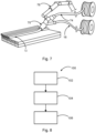
- eine schematische Darstellung einer Vorrichtung zur Herstellung einer Bipolarplatte.
- Fig. 8
- eine schematische Darstellung eines additiven Herstellungsverfahrens einer Bipolarplatte.
- Fig. 9
- eine schematische Darstellung eines Verfahrens zum Betreiben einer Brennstoffzelle.
- Fig. 10
- eine schematische Darstellung eines Luftfahrzeugs mit einer Brennstoffzelle.
-
Fig. 1 zeigt eine schematische Darstellung des prinzipiellen Aufbaus einer Brennstoffzelle gemäß dem Stand der Technik. Brennstoffzellen sind eine der vielversprechendsten Quellen umweltfreundlicher Energie für die Zukunft. Diese Systeme erzeugen elektrische Energie, indem sie die in einem Brennstoff, zum Beispiel Wasserstoff oder Methanol, gespeicherte chemische Energie durch Oxidations-Reduktionsreaktionen umwandeln. Das Prinzip der Brennstoffzelle basiert auf der Reaktionsgleichung 2 H2 + O2 = 2 H2O. Der Brennstoffzelle wird dabei H2 zugeführt, links, welcher eine Anode umströmt und teilweise wieder als ΔH2 austritt. Die Wasserstoffmoleküle des H2 zerfallen dabei zu geladenen Wasserstoffatomen, Wasserstoff-Ionen H+, und geben ein freies Elektron e- ab. Die freien Elektronen e- fließen als nutzbarer Strom über einen Leiter zur Kathode.
Dort bilden sie mit den Sauerstoffatomen negative Sauerstoff-Ionen O2-. Die Wasserstoff-Ionen H+wandern durch den Elektrolyten zur Kathode, wo sie sich mit den Sauerstoff-Ionen zu Wasser H2O vereinigen und dabei noch Wärme J freisetzen. -
Fig. 2 eine schematische Darstellung des Einflusses eines Magnetfelds auf ein Gasteilchen. Es ist bekannt, dass Magnetfelder einen Einfluss auf sich bewegende Gasteilchen haben. Bewegt sich ein Gasteilchen X mit der Masse m mit der Geschwindigkeit v durch den Raum und gerät in ein Magnetfeld mit der Stärke und Richtung M, so nimmt das Gasteilchen eine veränderte Richtung ein und wird mit der Beschleunigung a beschleunigt. Dieses Prinzip beschleunigt den Reaktanten und übt somit eine auf die Elektrodenoberfläche gerichtete Kraft aus. -
Fig. 3 zeigt einen elektrischen Draht, durch den ein elektrischer Strom fließt. In Flussrichtung gesehen, bildet sich um den Draht ein elektromagnetisches Feld.
Die Regel der "Rechtsschraube" besagt, dass sich das elektromagnetische Feld in Flussrichtung gesehen kreisförmig und im Uhrzeigersinn um den Draht ausbildet. - Es wird somit zusätzlich zum Gasströmungsdruck ein elektromagnetischer Einfluss auf die Reaktanten in den Strömungskanälen in der Bipolarplatte ausgeübt wird, um die Strömung zu den Elektroden zu verbessern.
-
Fig. 4 ist ein Detail einer Bipolarplatte 10 mit einem Gasströmungskanal 14 in dem Bipolarplattenkörper 12 mit einer ersten Oberfläche 13 dargestellt. In der ersten Gasströmungskanalseitenwand des Gasströmungskanals 14 ist ein elektrischer Leiter 16 eingebettet. Dieser Leiter kann durch additive Fertigung der Bipolarplatte 12 mit einem koaxialen Druckkopf in seine Position gebracht werden. Der elektrische Leiter 12 verläuft dabei parallel zu einem Gasströmungskanal, wobei über eine Stromquelle 22 elektrischer Strom und ein elektromagnetisches Feld M⊘ im Gasströmungskanal 14 wirken. Über das Prinzip der Rechtsschraube werden sich im Gasströmungskanal 14 befindliche Reaktanten nun in Richtung der ersten Oberfläche 13 beschleunigt. -
Fig. 5 zeigt das gleiche Detail einer Bipolarplatte 10 mit Gasströmungskanal 14. Nun sind mehrere elektrische Leiter 16 in den Kanalseitenwänden der Bipolarplatte 10 entlang des Gasströmungskanals 14 in mehreren Reihen angeordnet und bilden ein "Band" von elektrischen Leitern 16. Wenn elektrischer Strom durch diese elektrische Leiter 16 fließt, bilden sich mehrere elektromagnetische Felder, eines um jeden elektrischen Leiter 16. Auf jeder Seite des "Bands" bildet sich ein elektromagnetisches Feld, das parallel zum "Band" ausgerichtet ist. Reaktanten 15, die sich im Gasströmungskanal 14 bewegen, werden durch das elektromagnetische Feld beeinflusst und beschleunigt. Wenn die elektrischen Leiter 16 im richtigen Winkel ausgerichtet sind und elektrischer Strom in der richtigen Richtung durch sie fließt, können die Reaktanten 15 zur Elektrode 24 hin beschleunigt werden. -
Fig. 6 zeigt eine schematische Darstellung eines Brennstoffzellenstapel 50. Da die maximal erzielbare Zellenspannung einer Einzelzelle physikalisch begrenzt ist und im Anwendungsfall regelmäßig unter 1V, typischerweise im Bereich 0,5 bis 0,7V liegt, werden zur Herstellung höherer Spannungen und Leistungen mehrere Einzelzellen in Form einer elektrischen Serienschaltung zusammengeschaltet.
Dieser im folgenden als Stapelaufbau bezeichnete Komplex besteht aus einer oder mehreren aufeinander gestapelten und in einer elektrischen Serienschaltung angeordneten, planaren Einzelzellen. Der Stapelaufbau wird an beiden Enden durch sogenannte Stromabnehmerplatten zur Abnahme des elektrischen Stroms versehen und durch eine - meist plattenförmige - und zum Stapelaufbau gehörende Isolierung elektrisch von den sogenannten Endplatten getrennt. Die Endplatten sind an beiden Enden des Stapelaufbaus angeordnet und meist durch Zuganker miteinander verbunden. Durch diese Zuganker ist die Aufbringung einer Verspannungskraft bzw. einer Druckkraft auf den Stapelaufbau möglich. -
Fig. 7 zeigt eine schematische Darstellung einer Vorrichtung zur Herstellung einer Bipolarplatte. Über einen koaxialen Druckkopf 70 wird aus einem elektrischen Leiter 16 und einem thermoplastischen Filament 74 ein koaxiales Filament 72 gebildet. Ein Roboterarm 76 ist eingerichtet die einzelnen Filamente nebeneinander abzulegen und somit den Bipolarplattenkörper 12 aufzubauen. - Der elektrische Leiter 16 kann dabei als Endlosfaser vorliegen und aus einer oder mehreren Kohlenstofffasern oder aus einem elektrischen Metalldraht bestehen.
-
Fig. 8 zeigt eine schematische Darstellung eines additiven Herstellungsverfahrens einer Bipolarplatte. Das Verfahren 100 weist die folgenden Schritte auf. Zu Beginn wird ein elektrischer Leiter 16 und ein thermoplastischer Isolationswerkstoff 74 bereitgestellt. Der elektrische Leiter 16 wird mit dem thermoplastischen Isolationswerkstoff über einen Druckkopf, der dafür vorgesehen ist, ein koaxiales Kabel herzustellen, ummantelt. Das koaxiale Kabel 72 wird zu einem Bipolarplattenkörper 12 abgelegt, wobei der Bipolarplattenkörper 12 auf der ersten Oberfläche 13 mindestens einen Gasströmungskanal 14 aufweist. Wird nun an den elektrischen Leiter 16 eine Spannung angelegten, bildet der elektrische Leiter 16 ein elektromagnetisches Feld aus, wobei das elektromagnetisches Feld dafür vorgesehen ist, einen Reaktant 15 zumindest teilweise in Richtung einer mit dem Bipolarplatte 10 in Kontakt stehenden Elektrode zu beschleunigen. - Das Verfahren 100 wird vorzugsweise unter Einsatz einer in
Fig. 7 beschriebenen Vorrichtung durchgeführt, wobei der elektrische Leiter 16 eine Vielzahl von elektrischen Leitern umfasst. -
Fig. 9 zeigt eine schematische Darstellung eines Verfahrens 200 zum Betreiben einer Brennstoffzelle, wobei das Verfahren die folgenden Schritte aufweist.
Es ist eine Verbindung der Brennstoffzelle 10 mit einem kryogenem Wasserstoff enthaltenden Tank über eine erste Gasleitung vorgesehen 202. Der kryogene Wasserstoff wird durch Aussetzen der ersten Gasleitung an die durch den Betrieb der Brennstoffzelle 10 entstehende Abwärme erwärmt 204 während der Hochtemperatur-Supraleiter über eine durch den kryogenen Wasserstoff induzierte Wärmesenke gekühlt wird. Wird nun an den Hochtemperatur-Supraleiter eine Spannung angelegt, bildet der Hochtemperatur-Supraleiter ein elektromagnetisches Feld ausbildet, wobei das elektromagnetisches Feld dafür vorgesehen ist, den Reaktant zumindest teilweise in Richtung der Elektrode zu beschleunigen. - Das Verfahren 200 liefert somit mehrere Vorteile. Der kryogene Wasserstoff wird über die Wärme der Brennstoffzelle 10 erwärmt, wodurch die notwendige zuzuführende Energie zum Aufwärmen des kryogenen Wasserstoffs reduziert werden kann. Gleichzeitig wird über die, durch den kryogenen Wasserstoff induzierte, Wärmesenke die Temperatur des Supraleiters vorteilhaft herabgesetzt.
-
Fig. 10 eine schematische Darstellung eines Luftfahrzeugs mit einer Brennstoffzelle. Unter einem Luftfahrzeug kann dabei ein Passagierflugzeug, ein Helikopter, eine Drohne, ein Luftschiff oder ein Segelflugzeug zu verstehen sein. - Die optimale Lage und Anzahl der elektrischen Leitungen muss durch Berechnungen und anschließende Tests ermittelt werden. Die elektrischen Leitungen können mit einer Steuereinheit verbunden werden, die den Betrieb der Brennstoffzelle steuert, einschließlich Gasdruck, benötigte Leistung der Flugsteuerung usw.
- Ergänzend ist darauf hinzuweisen, dass "umfassend" oder "aufweisend" keine anderen Elemente oder Schritte ausschließt und "eine" oder "ein" keine Vielzahl ausschließt. Ferner sei darauf hingewiesen, dass Merkmale oder Schritte, die mit Verweis auf eines der obigen Ausführungsbeispiele beschrieben worden sind, auch in Kombination mit anderen Merkmalen oder Schritten anderer oben beschriebener Ausführungsbeispiele verwendet werden können. Bezugszeichen in den Ansprüchen sind nicht als Einschränkung anzusehen.
-
- 10
- Bipolarplatte
- 12
- Bipolarplattenkörper
- 13
- erste Oberfläche
- 14
- Gasströmungskanal
- 15
- Reaktant
- 16
- elektrischer Leiter
- 20
- Membran
- 22
- Stromquelle
- 24
- Elektrode
- 50
- Brennstoffzellenstapel
- 70
- Koaxialer Druckkopf
- 72
- Koaxiales Filament
- 74
- Thermoplastisches Filament
- 76
- Roboterarm
- 100
- Fertigungsverfahren
- 102
- Bereitstellen
- 104
- Ablegen
- 200
- Verfahren zum Betreiben
- 202
- Vorsehen
- 204
- Erwärmen
- 300
- Luftfahrzeug
Claims (15)
- Bipolarplatte (10) für eine Brennstoffzelle zur Erzeugung von elektrischem Strom, aufweisend:einen Bipolarplattenkörper (12) mit einer ersten Oberfläche (13), wobei der Bipolarplattenkörper (12) eingerichtet ist über die erste Oberfläche (13) mit einer Elektrode in Kontakt zu stehen,
wobei der Bipolarplattenkörper (12) auf der ersten Oberfläche (13) mindestens einen Gasströmungskanal (14) aufweist,wobei der Gasströmungskanal (14) eine erste Gasströmungskanalseitenwand und eine gegenüberliegende zweite Gasströmungskanalseitenwand definiert, undwobei der Gasströmungskanal (14) entlang einer ersten Richtung verläuft und dafür vorgesehen ist, einen Reaktanten (15) mit der Elektrode in Kontakt zu bringen, undmindestens einen elektrischen Leiter (16),
wobei der mindestens eine elektrische Leiter (16) eingerichtet ist, innerhalb des Bipolarplattenkörpers (12) hinter der ersten Gasströmungskanalseitenwand und/oder der zweiten Gasströmungskanalseitenwand zumindest teilweise parallel zu der ersten Richtung zu verlaufen,derart, dass sich bei einer an den elektrischen Leiter (16) angelegten Spannung der elektrische Leiter (16) ein elektromagnetisches Feld ausbildet, wobei das elektromagnetisches Feld dafür vorgesehen ist, den Reaktant (15) zumindest teilweise in Richtung der Elektrode zu beschleunigen. - Bipolarplatte (10) nach Anspruch 1,
wobei der mindestens eine elektrische Leiter (16) eine Vielzahl von elektrischen Leitern ist. - Bipolarplatte (10) nach Anspruch 1 oder 2,
wobei der mindestens eine elektrische Leiter (16) ein Metall aufweist, insbesondere ausgewählt aus der Gruppe: Kupfer, Gold,... - Bipolarplatte (10) nach Anspruch 1 oder 2,
wobei der mindestens eine elektrische Leiter (16) eine graphenbeschichtete Kohlefaser aufweist. - Bipolarplatte (10) nach Anspruch 1 oder 2,
wobei der mindestens eine elektrische Leiter (16) einen Hochtemperatur-Supraleiter aufweist. - Bipolarplatte (10) nach einem der Ansprüche 1 bis 5,
wobei der Bipolarplattenkörper (12) eine Keramik aufweist. - Bipolarplatte (10) nach einem der Ansprüche 1 bis 5,
wobei der Bipolarplattenkörper (12) einen kohlefaserverstärkten Kunststoff aufweist. - Bipolarplatte (10) nach einem der Ansprüche 1 bis 5,
wobei der Bipolarplattenkörper (12) einen kohlefaserverstärkten Kohlenstoff aufweist. - Brennstoffzelle, aufweisend eine Bipolarplatte (10) nach einem der Ansprüche 1 bis 8,wobei die Brennstoffzelle (50) ferner eine Steuereinheit aufweist,wobei die Steuereinheit dafür vorgesehen ist, den mindestens einen elektrischen Leiter (16) anzusteuern.
- Brennstoffzelle nach Anspruch 9,wobei die die Brennstoffzelle eingerichtet ist über eine erste Gasleitung mit einem kryogenem Wasserstoff enthaltenden Tank verbindbar zu sein, undwobei der mindestens eine elektrische Leiter ein Hochtemperatur-Supraleiter ist,und die Brennstoffzelle eingerichtet ist, mit der ersten Gasleitung derart in thermischer Wechselwirkung zu stehen,so dass eine durch den kryogenen Wasserstoff induzierte Wärmesenke in der ersten Gasleitung den Hochtemperatur-Supraleiter kühlt, und die Brennstoffzelle (10) den kryogenen Wasserstoff durch Aussetzen der ersten Gasleitung an die durch den Betrieb der Brennstoffzelle (10) entstehende Abwärme erwärmt.
- Brennstoffzellenstapel (50), aufweisend eine Mehrzahl von Brennstoffzellen nach den Ansprüchen 9 oder 10.
- Verfahren (100), insbesondere additives Fertigungsverfahren, zur Herstellung einer Bipolarplatte (10) nach einem der Ansprüche 1 bis 8, aufweisend die folgenden Schritte:Bereitstellen (102) eines elektrischen Leiters (16),
Bereitstellen (104) eines thermoplastischen Isolationswerkstoffs,Ummanteln (106) des elektrischen Leiters (16) mit dem thermoplastischen Isolationswerkstoff mit einem Druckkopf, der dafür vorgesehen ist ein koaxiales Kabel herzustellen,Ablegen (108) des koaxialen Kabels zu einem Bipolarplattenkörper (12), wobei der Bipolarplattenkörper (12) auf der ersten Oberfläche (13) mindestens einen Gasströmungskanal (14) aufweist,
derart, dass bei einer an den elektrischen Leiter (16) angelegten Spannung der elektrische Leiter (16) ein elektromagnetisches Feld ausbildet, wobei das elektromagnetisches Feld dafür vorgesehen ist, den Reaktant zumindest teilweise in Richtung der Elektrode zu beschleunigen. - Verfahren (100) nach Anspruch 13,
wobei der elektrische Leiter (16) eine Vielzahl von elektrischen Leitern umfasst. - Verfahren (200) zum Betreiben einer Brennstoffzelle (10) nach Anspruch 10, aufweisend die folgenden Schritte:Vorsehen (202) einer Verbindung der Brennstoffzelle (10) mit einem kryogenem Wasserstoff enthaltenden Tank über eine erste Gasleitung,Erwärmen (204) des kryogenen Wasserstoffs durch Aussetzen der ersten Gasleitung an die durch den Betrieb der Brennstoffzelle (10) entstehende Abwärme,Kühlen (206) der Hochtemperatur-Supraleiter über eine durch den kryogenen Wasserstoff induzierte Wärmesenke,derart, dass bei einer an den Hochtemperatur-Supraleiter angelegten Spannung der Hochtemperatur-Supraleiter ein elektromagnetisches Feld ausbildet, wobei das elektromagnetisches Feld dafür vorgesehen ist, den Reaktant zumindest teilweise in Richtung der Elektrode zu beschleunigen.
- Luftfahrzeug (300), aufweisend eine Brennstoffzelle (10) nach einem der Ansprüche 1 bis 9.
Priority Applications (3)
| Application Number | Priority Date | Filing Date | Title |
|---|---|---|---|
| EP21207287.0A EP4177991B1 (de) | 2021-11-09 | 2021-11-09 | Bipolarplatte für eine brennstoffzelle mit integrierter leiteranordnung zur erzeugung eines gerichteten elektromagnetischen feldes |
| CN202211332045.XA CN116111125A (zh) | 2021-11-09 | 2022-10-28 | 用于产生电流的燃料电池的双极板 |
| US17/981,645 US12381234B2 (en) | 2021-11-09 | 2022-11-07 | Bipolar plate for a fuel cell for generation of electrical power |
Applications Claiming Priority (1)
| Application Number | Priority Date | Filing Date | Title |
|---|---|---|---|
| EP21207287.0A EP4177991B1 (de) | 2021-11-09 | 2021-11-09 | Bipolarplatte für eine brennstoffzelle mit integrierter leiteranordnung zur erzeugung eines gerichteten elektromagnetischen feldes |
Publications (2)
| Publication Number | Publication Date |
|---|---|
| EP4177991A1 true EP4177991A1 (de) | 2023-05-10 |
| EP4177991B1 EP4177991B1 (de) | 2024-05-01 |
Family
ID=78592677
Family Applications (1)
| Application Number | Title | Priority Date | Filing Date |
|---|---|---|---|
| EP21207287.0A Active EP4177991B1 (de) | 2021-11-09 | 2021-11-09 | Bipolarplatte für eine brennstoffzelle mit integrierter leiteranordnung zur erzeugung eines gerichteten elektromagnetischen feldes |
Country Status (3)
| Country | Link |
|---|---|
| US (1) | US12381234B2 (de) |
| EP (1) | EP4177991B1 (de) |
| CN (1) | CN116111125A (de) |
Citations (4)
| Publication number | Priority date | Publication date | Assignee | Title |
|---|---|---|---|---|
| JPS6191876A (ja) * | 1984-10-08 | 1986-05-09 | Toshiba Corp | 燃料電池装置 |
| US5817221A (en) * | 1994-08-25 | 1998-10-06 | University Of Iowa Research Foundation | Composites formed using magnetizable material, a catalyst and an electron conductor |
| US20040018400A1 (en) * | 2002-07-23 | 2004-01-29 | Gregory Herman | Method and apparatus for increasing fuel cell efficiency, power output, or reduced-temperature operation |
| CN112331891A (zh) * | 2020-10-19 | 2021-02-05 | 国科微城市智能科技(南京)有限责任公司 | 一种促进氢燃料电池氢原子加速分解的方法 |
Family Cites Families (2)
| Publication number | Priority date | Publication date | Assignee | Title |
|---|---|---|---|---|
| TWI404259B (zh) * | 2010-08-06 | 2013-08-01 | Univ Nat Chiao Tung | 燃料電池、具有面穿透導電性之板體及其製作方法 |
| DE102018008249A1 (de) * | 2018-10-18 | 2020-04-23 | Daimler Ag | Verfahren zur Herstellung einer Separatorplatte |
-
2021
- 2021-11-09 EP EP21207287.0A patent/EP4177991B1/de active Active
-
2022
- 2022-10-28 CN CN202211332045.XA patent/CN116111125A/zh active Pending
- 2022-11-07 US US17/981,645 patent/US12381234B2/en active Active
Patent Citations (4)
| Publication number | Priority date | Publication date | Assignee | Title |
|---|---|---|---|---|
| JPS6191876A (ja) * | 1984-10-08 | 1986-05-09 | Toshiba Corp | 燃料電池装置 |
| US5817221A (en) * | 1994-08-25 | 1998-10-06 | University Of Iowa Research Foundation | Composites formed using magnetizable material, a catalyst and an electron conductor |
| US20040018400A1 (en) * | 2002-07-23 | 2004-01-29 | Gregory Herman | Method and apparatus for increasing fuel cell efficiency, power output, or reduced-temperature operation |
| CN112331891A (zh) * | 2020-10-19 | 2021-02-05 | 国科微城市智能科技(南京)有限责任公司 | 一种促进氢燃料电池氢原子加速分解的方法 |
Also Published As
| Publication number | Publication date |
|---|---|
| EP4177991B1 (de) | 2024-05-01 |
| US12381234B2 (en) | 2025-08-05 |
| US20230140875A1 (en) | 2023-05-11 |
| CN116111125A (zh) | 2023-05-12 |
Similar Documents
| Publication | Publication Date | Title |
|---|---|---|
| EP0797847B1 (de) | Polymerelektrolyt-membran-brennstoffzelle | |
| DE102016225651B4 (de) | Endzellen-Heizungsanordnung und Brennstoffzellenstapel mit derselben | |
| EP0797848B1 (de) | Pem-brennstoffzelle mit strukturierten platten | |
| DE10392620T5 (de) | Brennstoffzellenstapel mit verbesserter Druckplatte und verbessertem Stromkollektor | |
| DE19624887A1 (de) | Elektrochemisches Festelektrolyt-Zellsystem | |
| WO2018015189A1 (de) | Verfahren zur herstellung einer bipolarplatte für eine brennstoffzelle und brennstoffzelle | |
| WO2020193055A1 (de) | Bipolarplatte für einen brennstoffzellenstapel und brennstoffzellenstapel | |
| DE102014215827B4 (de) | Brennstoffzelle mit einer integrierten Membranelektrodenanordnung und Gasdiffusionsschicht und entsprechendes Herstellungsverfahren | |
| DE102014210358A1 (de) | Brennstoffzellenstapel mit einer dummyzelle | |
| EP2130256B1 (de) | Brennstoffzellenstack in leichtbauweise | |
| EP1236235B1 (de) | Strom- und gasverteilerstruktur für elektrochemische zelle | |
| DE102019203373A1 (de) | Gasdiffusionslage für eine Brennstoffzelle und Brennstoffzelle | |
| EP4177991B1 (de) | Bipolarplatte für eine brennstoffzelle mit integrierter leiteranordnung zur erzeugung eines gerichteten elektromagnetischen feldes | |
| WO2015155125A1 (de) | Bipolarplatte und brennstoffzelle | |
| EP1084517A1 (de) | Verfahren zum herstellen einer elektrode sowie eine elektrode für eine brennstoffzelle | |
| EP4165703B1 (de) | Bipolarplatte mit einsetzbarer blende und brennstoffzellenstapel | |
| DE102019206117A1 (de) | Brennstoffzellenstapel umfassend variable Biopolarplatten | |
| EP4584828B1 (de) | Verfahren zur herstellung einer elektrode, elektrode, alkali-batterie und verwendungen der alkali-batterie | |
| DE102015215381A1 (de) | Membran-Elektroden-Einheit für eine Brennstoffzelle sowie Brennstoffzelle | |
| EP1776728A2 (de) | Brennstoffzellen-system | |
| EP1327274B1 (de) | Brennstoffzellenmodul | |
| DE102021206090A1 (de) | Wasserstoff- und Kühlmittel Flow-Field-Design ohne Kühlmittelverteilungsbereich einer Bipolarplatte für PEM-Brennstoffzellen und Elektrolyseure | |
| DE20305084U1 (de) | Stromabnahmeplatte für eine Brennstoffzelle | |
| DE102020007226A1 (de) | Vorrichtung zur Abschirmung elektromagnetischer Störungen | |
| EP4647536A1 (de) | Elektrolyseur mit einem zwischen zellteilstapeln angeordnetem isolator |
Legal Events
| Date | Code | Title | Description |
|---|---|---|---|
| PUAI | Public reference made under article 153(3) epc to a published international application that has entered the european phase |
Free format text: ORIGINAL CODE: 0009012 |
|
| STAA | Information on the status of an ep patent application or granted ep patent |
Free format text: STATUS: THE APPLICATION HAS BEEN PUBLISHED |
|
| AK | Designated contracting states |
Kind code of ref document: A1 Designated state(s): AL AT BE BG CH CY CZ DE DK EE ES FI FR GB GR HR HU IE IS IT LI LT LU LV MC MK MT NL NO PL PT RO RS SE SI SK SM TR |
|
| STAA | Information on the status of an ep patent application or granted ep patent |
Free format text: STATUS: REQUEST FOR EXAMINATION WAS MADE |
|
| GRAP | Despatch of communication of intention to grant a patent |
Free format text: ORIGINAL CODE: EPIDOSNIGR1 |
|
| STAA | Information on the status of an ep patent application or granted ep patent |
Free format text: STATUS: GRANT OF PATENT IS INTENDED |
|
| 17P | Request for examination filed |
Effective date: 20231110 |
|
| RBV | Designated contracting states (corrected) |
Designated state(s): AL AT BE BG CH CY CZ DE DK EE ES FI FR GB GR HR HU IE IS IT LI LT LU LV MC MK MT NL NO PL PT RO RS SE SI SK SM TR |
|
| RIC1 | Information provided on ipc code assigned before grant |
Ipc: B33Y 80/00 20150101ALI20231129BHEP Ipc: B29C 64/10 20170101ALI20231129BHEP Ipc: H01M 8/04746 20160101ALI20231129BHEP Ipc: H01M 8/04223 20160101ALI20231129BHEP Ipc: H01M 8/04089 20160101ALI20231129BHEP Ipc: H01M 8/04082 20160101ALI20231129BHEP Ipc: H01M 8/04014 20160101ALI20231129BHEP Ipc: H01M 8/0213 20160101ALI20231129BHEP Ipc: H01M 8/0215 20160101AFI20231129BHEP |
|
| INTG | Intention to grant announced |
Effective date: 20231212 |
|
| GRAS | Grant fee paid |
Free format text: ORIGINAL CODE: EPIDOSNIGR3 |
|
| GRAA | (expected) grant |
Free format text: ORIGINAL CODE: 0009210 |
|
| STAA | Information on the status of an ep patent application or granted ep patent |
Free format text: STATUS: THE PATENT HAS BEEN GRANTED |
|
| AK | Designated contracting states |
Kind code of ref document: B1 Designated state(s): AL AT BE BG CH CY CZ DE DK EE ES FI FR GB GR HR HU IE IS IT LI LT LU LV MC MK MT NL NO PL PT RO RS SE SI SK SM TR |
|
| REG | Reference to a national code |
Ref country code: GB Ref legal event code: FG4D Free format text: NOT ENGLISH |
|
| REG | Reference to a national code |
Ref country code: CH Ref legal event code: EP |
|
| REG | Reference to a national code |
Ref country code: DE Ref legal event code: R096 Ref document number: 502021003552 Country of ref document: DE |
|
| REG | Reference to a national code |
Ref country code: IE Ref legal event code: FG4D Free format text: LANGUAGE OF EP DOCUMENT: GERMAN |
|
| REG | Reference to a national code |
Ref country code: LT Ref legal event code: MG9D |
|
| REG | Reference to a national code |
Ref country code: NL Ref legal event code: MP Effective date: 20240501 |
|
| PG25 | Lapsed in a contracting state [announced via postgrant information from national office to epo] |
Ref country code: IS Free format text: LAPSE BECAUSE OF FAILURE TO SUBMIT A TRANSLATION OF THE DESCRIPTION OR TO PAY THE FEE WITHIN THE PRESCRIBED TIME-LIMIT Effective date: 20240901 |
|
| PG25 | Lapsed in a contracting state [announced via postgrant information from national office to epo] |
Ref country code: BG Free format text: LAPSE BECAUSE OF FAILURE TO SUBMIT A TRANSLATION OF THE DESCRIPTION OR TO PAY THE FEE WITHIN THE PRESCRIBED TIME-LIMIT Effective date: 20240501 |
|
| PG25 | Lapsed in a contracting state [announced via postgrant information from national office to epo] |
Ref country code: FI Free format text: LAPSE BECAUSE OF FAILURE TO SUBMIT A TRANSLATION OF THE DESCRIPTION OR TO PAY THE FEE WITHIN THE PRESCRIBED TIME-LIMIT Effective date: 20240501 Ref country code: HR Free format text: LAPSE BECAUSE OF FAILURE TO SUBMIT A TRANSLATION OF THE DESCRIPTION OR TO PAY THE FEE WITHIN THE PRESCRIBED TIME-LIMIT Effective date: 20240501 |
|
| PG25 | Lapsed in a contracting state [announced via postgrant information from national office to epo] |
Ref country code: GR Free format text: LAPSE BECAUSE OF FAILURE TO SUBMIT A TRANSLATION OF THE DESCRIPTION OR TO PAY THE FEE WITHIN THE PRESCRIBED TIME-LIMIT Effective date: 20240802 |
|
| PG25 | Lapsed in a contracting state [announced via postgrant information from national office to epo] |
Ref country code: PT Free format text: LAPSE BECAUSE OF FAILURE TO SUBMIT A TRANSLATION OF THE DESCRIPTION OR TO PAY THE FEE WITHIN THE PRESCRIBED TIME-LIMIT Effective date: 20240902 |
|
| PG25 | Lapsed in a contracting state [announced via postgrant information from national office to epo] |
Ref country code: NL Free format text: LAPSE BECAUSE OF FAILURE TO SUBMIT A TRANSLATION OF THE DESCRIPTION OR TO PAY THE FEE WITHIN THE PRESCRIBED TIME-LIMIT Effective date: 20240501 |
|
| PG25 | Lapsed in a contracting state [announced via postgrant information from national office to epo] |
Ref country code: ES Free format text: LAPSE BECAUSE OF FAILURE TO SUBMIT A TRANSLATION OF THE DESCRIPTION OR TO PAY THE FEE WITHIN THE PRESCRIBED TIME-LIMIT Effective date: 20240501 |
|
| PG25 | Lapsed in a contracting state [announced via postgrant information from national office to epo] |
Ref country code: PL Free format text: LAPSE BECAUSE OF FAILURE TO SUBMIT A TRANSLATION OF THE DESCRIPTION OR TO PAY THE FEE WITHIN THE PRESCRIBED TIME-LIMIT Effective date: 20240501 |
|
| PG25 | Lapsed in a contracting state [announced via postgrant information from national office to epo] |
Ref country code: LV Free format text: LAPSE BECAUSE OF FAILURE TO SUBMIT A TRANSLATION OF THE DESCRIPTION OR TO PAY THE FEE WITHIN THE PRESCRIBED TIME-LIMIT Effective date: 20240501 |
|
| PG25 | Lapsed in a contracting state [announced via postgrant information from national office to epo] |
Ref country code: PT Free format text: LAPSE BECAUSE OF FAILURE TO SUBMIT A TRANSLATION OF THE DESCRIPTION OR TO PAY THE FEE WITHIN THE PRESCRIBED TIME-LIMIT Effective date: 20240902 Ref country code: PL Free format text: LAPSE BECAUSE OF FAILURE TO SUBMIT A TRANSLATION OF THE DESCRIPTION OR TO PAY THE FEE WITHIN THE PRESCRIBED TIME-LIMIT Effective date: 20240501 Ref country code: NO Free format text: LAPSE BECAUSE OF FAILURE TO SUBMIT A TRANSLATION OF THE DESCRIPTION OR TO PAY THE FEE WITHIN THE PRESCRIBED TIME-LIMIT Effective date: 20240801 Ref country code: NL Free format text: LAPSE BECAUSE OF FAILURE TO SUBMIT A TRANSLATION OF THE DESCRIPTION OR TO PAY THE FEE WITHIN THE PRESCRIBED TIME-LIMIT Effective date: 20240501 Ref country code: LV Free format text: LAPSE BECAUSE OF FAILURE TO SUBMIT A TRANSLATION OF THE DESCRIPTION OR TO PAY THE FEE WITHIN THE PRESCRIBED TIME-LIMIT Effective date: 20240501 Ref country code: IS Free format text: LAPSE BECAUSE OF FAILURE TO SUBMIT A TRANSLATION OF THE DESCRIPTION OR TO PAY THE FEE WITHIN THE PRESCRIBED TIME-LIMIT Effective date: 20240901 Ref country code: HR Free format text: LAPSE BECAUSE OF FAILURE TO SUBMIT A TRANSLATION OF THE DESCRIPTION OR TO PAY THE FEE WITHIN THE PRESCRIBED TIME-LIMIT Effective date: 20240501 Ref country code: GR Free format text: LAPSE BECAUSE OF FAILURE TO SUBMIT A TRANSLATION OF THE DESCRIPTION OR TO PAY THE FEE WITHIN THE PRESCRIBED TIME-LIMIT Effective date: 20240802 Ref country code: FI Free format text: LAPSE BECAUSE OF FAILURE TO SUBMIT A TRANSLATION OF THE DESCRIPTION OR TO PAY THE FEE WITHIN THE PRESCRIBED TIME-LIMIT Effective date: 20240501 Ref country code: ES Free format text: LAPSE BECAUSE OF FAILURE TO SUBMIT A TRANSLATION OF THE DESCRIPTION OR TO PAY THE FEE WITHIN THE PRESCRIBED TIME-LIMIT Effective date: 20240501 Ref country code: BG Free format text: LAPSE BECAUSE OF FAILURE TO SUBMIT A TRANSLATION OF THE DESCRIPTION OR TO PAY THE FEE WITHIN THE PRESCRIBED TIME-LIMIT Effective date: 20240501 Ref country code: RS Free format text: LAPSE BECAUSE OF FAILURE TO SUBMIT A TRANSLATION OF THE DESCRIPTION OR TO PAY THE FEE WITHIN THE PRESCRIBED TIME-LIMIT Effective date: 20240801 |
|
| PG25 | Lapsed in a contracting state [announced via postgrant information from national office to epo] |
Ref country code: DK Free format text: LAPSE BECAUSE OF FAILURE TO SUBMIT A TRANSLATION OF THE DESCRIPTION OR TO PAY THE FEE WITHIN THE PRESCRIBED TIME-LIMIT Effective date: 20240501 |
|
| PG25 | Lapsed in a contracting state [announced via postgrant information from national office to epo] |
Ref country code: EE Free format text: LAPSE BECAUSE OF FAILURE TO SUBMIT A TRANSLATION OF THE DESCRIPTION OR TO PAY THE FEE WITHIN THE PRESCRIBED TIME-LIMIT Effective date: 20240501 |
|
| PG25 | Lapsed in a contracting state [announced via postgrant information from national office to epo] |
Ref country code: CZ Free format text: LAPSE BECAUSE OF FAILURE TO SUBMIT A TRANSLATION OF THE DESCRIPTION OR TO PAY THE FEE WITHIN THE PRESCRIBED TIME-LIMIT Effective date: 20240501 |
|
| PG25 | Lapsed in a contracting state [announced via postgrant information from national office to epo] |
Ref country code: SK Free format text: LAPSE BECAUSE OF FAILURE TO SUBMIT A TRANSLATION OF THE DESCRIPTION OR TO PAY THE FEE WITHIN THE PRESCRIBED TIME-LIMIT Effective date: 20240501 Ref country code: RO Free format text: LAPSE BECAUSE OF FAILURE TO SUBMIT A TRANSLATION OF THE DESCRIPTION OR TO PAY THE FEE WITHIN THE PRESCRIBED TIME-LIMIT Effective date: 20240501 |
|
| PG25 | Lapsed in a contracting state [announced via postgrant information from national office to epo] |
Ref country code: SM Free format text: LAPSE BECAUSE OF FAILURE TO SUBMIT A TRANSLATION OF THE DESCRIPTION OR TO PAY THE FEE WITHIN THE PRESCRIBED TIME-LIMIT Effective date: 20240501 |
|
| PG25 | Lapsed in a contracting state [announced via postgrant information from national office to epo] |
Ref country code: SM Free format text: LAPSE BECAUSE OF FAILURE TO SUBMIT A TRANSLATION OF THE DESCRIPTION OR TO PAY THE FEE WITHIN THE PRESCRIBED TIME-LIMIT Effective date: 20240501 Ref country code: SK Free format text: LAPSE BECAUSE OF FAILURE TO SUBMIT A TRANSLATION OF THE DESCRIPTION OR TO PAY THE FEE WITHIN THE PRESCRIBED TIME-LIMIT Effective date: 20240501 Ref country code: RO Free format text: LAPSE BECAUSE OF FAILURE TO SUBMIT A TRANSLATION OF THE DESCRIPTION OR TO PAY THE FEE WITHIN THE PRESCRIBED TIME-LIMIT Effective date: 20240501 Ref country code: EE Free format text: LAPSE BECAUSE OF FAILURE TO SUBMIT A TRANSLATION OF THE DESCRIPTION OR TO PAY THE FEE WITHIN THE PRESCRIBED TIME-LIMIT Effective date: 20240501 Ref country code: DK Free format text: LAPSE BECAUSE OF FAILURE TO SUBMIT A TRANSLATION OF THE DESCRIPTION OR TO PAY THE FEE WITHIN THE PRESCRIBED TIME-LIMIT Effective date: 20240501 Ref country code: CZ Free format text: LAPSE BECAUSE OF FAILURE TO SUBMIT A TRANSLATION OF THE DESCRIPTION OR TO PAY THE FEE WITHIN THE PRESCRIBED TIME-LIMIT Effective date: 20240501 |
|
| REG | Reference to a national code |
Ref country code: DE Ref legal event code: R097 Ref document number: 502021003552 Country of ref document: DE |
|
| PG25 | Lapsed in a contracting state [announced via postgrant information from national office to epo] |
Ref country code: IT Free format text: LAPSE BECAUSE OF FAILURE TO SUBMIT A TRANSLATION OF THE DESCRIPTION OR TO PAY THE FEE WITHIN THE PRESCRIBED TIME-LIMIT Effective date: 20240501 |
|
| PLBE | No opposition filed within time limit |
Free format text: ORIGINAL CODE: 0009261 |
|
| STAA | Information on the status of an ep patent application or granted ep patent |
Free format text: STATUS: NO OPPOSITION FILED WITHIN TIME LIMIT |
|
| 26N | No opposition filed |
Effective date: 20250204 |
|
| PG25 | Lapsed in a contracting state [announced via postgrant information from national office to epo] |
Ref country code: SI Free format text: LAPSE BECAUSE OF FAILURE TO SUBMIT A TRANSLATION OF THE DESCRIPTION OR TO PAY THE FEE WITHIN THE PRESCRIBED TIME-LIMIT Effective date: 20240501 |
|
| REG | Reference to a national code |
Ref country code: CH Ref legal event code: PL |
|
| PG25 | Lapsed in a contracting state [announced via postgrant information from national office to epo] |
Ref country code: MC Free format text: LAPSE BECAUSE OF FAILURE TO SUBMIT A TRANSLATION OF THE DESCRIPTION OR TO PAY THE FEE WITHIN THE PRESCRIBED TIME-LIMIT Effective date: 20240501 |
|
| PG25 | Lapsed in a contracting state [announced via postgrant information from national office to epo] |
Ref country code: LU Free format text: LAPSE BECAUSE OF NON-PAYMENT OF DUE FEES Effective date: 20241109 |
|
| REG | Reference to a national code |
Ref country code: CH Ref legal event code: PL |
|
| PG25 | Lapsed in a contracting state [announced via postgrant information from national office to epo] |
Ref country code: CH Free format text: LAPSE BECAUSE OF NON-PAYMENT OF DUE FEES Effective date: 20241130 |
|
| REG | Reference to a national code |
Ref country code: BE Ref legal event code: MM Effective date: 20241130 |
|
| PG25 | Lapsed in a contracting state [announced via postgrant information from national office to epo] |
Ref country code: SE Free format text: LAPSE BECAUSE OF FAILURE TO SUBMIT A TRANSLATION OF THE DESCRIPTION OR TO PAY THE FEE WITHIN THE PRESCRIBED TIME-LIMIT Effective date: 20240501 |
|
| PG25 | Lapsed in a contracting state [announced via postgrant information from national office to epo] |
Ref country code: BE Free format text: LAPSE BECAUSE OF NON-PAYMENT OF DUE FEES Effective date: 20241130 |
|
| PG25 | Lapsed in a contracting state [announced via postgrant information from national office to epo] |
Ref country code: IE Free format text: LAPSE BECAUSE OF NON-PAYMENT OF DUE FEES Effective date: 20241109 |
|
| PGFP | Annual fee paid to national office [announced via postgrant information from national office to epo] |
Ref country code: DE Payment date: 20251119 Year of fee payment: 5 |
|
| PGFP | Annual fee paid to national office [announced via postgrant information from national office to epo] |
Ref country code: GB Payment date: 20251121 Year of fee payment: 5 |
|
| PGFP | Annual fee paid to national office [announced via postgrant information from national office to epo] |
Ref country code: AT Payment date: 20260113 Year of fee payment: 5 |
|
| PGFP | Annual fee paid to national office [announced via postgrant information from national office to epo] |
Ref country code: FR Payment date: 20251126 Year of fee payment: 5 |
|
| PG25 | Lapsed in a contracting state [announced via postgrant information from national office to epo] |
Ref country code: HU Free format text: LAPSE BECAUSE OF FAILURE TO SUBMIT A TRANSLATION OF THE DESCRIPTION OR TO PAY THE FEE WITHIN THE PRESCRIBED TIME-LIMIT; INVALID AB INITIO Effective date: 20211109 |
|
| PG25 | Lapsed in a contracting state [announced via postgrant information from national office to epo] |
Ref country code: CY Free format text: LAPSE BECAUSE OF FAILURE TO SUBMIT A TRANSLATION OF THE DESCRIPTION OR TO PAY THE FEE WITHIN THE PRESCRIBED TIME-LIMIT; INVALID AB INITIO Effective date: 20211109 |