EP4177631A2 - Lichtprojektionsvorrichtung, abstandsmessvorrichtung und lichtprojektionssteuerungsverfahren für laserlicht - Google Patents
Lichtprojektionsvorrichtung, abstandsmessvorrichtung und lichtprojektionssteuerungsverfahren für laserlicht Download PDFInfo
- Publication number
- EP4177631A2 EP4177631A2 EP22193426.8A EP22193426A EP4177631A2 EP 4177631 A2 EP4177631 A2 EP 4177631A2 EP 22193426 A EP22193426 A EP 22193426A EP 4177631 A2 EP4177631 A2 EP 4177631A2
- Authority
- EP
- European Patent Office
- Prior art keywords
- light
- light projecting
- optical signal
- signal
- optical
- Prior art date
- Legal status (The legal status is an assumption and is not a legal conclusion. Google has not performed a legal analysis and makes no representation as to the accuracy of the status listed.)
- Pending
Links
- 238000000034 method Methods 0.000 title claims description 11
- 230000003287 optical effect Effects 0.000 claims abstract description 162
- 238000012937 correction Methods 0.000 claims description 39
- 230000008859 change Effects 0.000 claims description 8
- 238000010586 diagram Methods 0.000 description 29
- 230000007423 decrease Effects 0.000 description 5
- 238000001514 detection method Methods 0.000 description 5
- 238000005259 measurement Methods 0.000 description 3
- 230000007246 mechanism Effects 0.000 description 2
- 239000004065 semiconductor Substances 0.000 description 2
- 230000007480 spreading Effects 0.000 description 2
- 230000001427 coherent effect Effects 0.000 description 1
- 230000003247 decreasing effect Effects 0.000 description 1
- 238000013461 design Methods 0.000 description 1
- 238000005286 illumination Methods 0.000 description 1
- 238000009434 installation Methods 0.000 description 1
- 238000004519 manufacturing process Methods 0.000 description 1
- 238000012986 modification Methods 0.000 description 1
- 230000004048 modification Effects 0.000 description 1
- 238000007493 shaping process Methods 0.000 description 1
- 238000006467 substitution reaction Methods 0.000 description 1
Images




Classifications
-
- G—PHYSICS
- G01—MEASURING; TESTING
- G01S—RADIO DIRECTION-FINDING; RADIO NAVIGATION; DETERMINING DISTANCE OR VELOCITY BY USE OF RADIO WAVES; LOCATING OR PRESENCE-DETECTING BY USE OF THE REFLECTION OR RERADIATION OF RADIO WAVES; ANALOGOUS ARRANGEMENTS USING OTHER WAVES
- G01S7/00—Details of systems according to groups G01S13/00, G01S15/00, G01S17/00
- G01S7/48—Details of systems according to groups G01S13/00, G01S15/00, G01S17/00 of systems according to group G01S17/00
- G01S7/481—Constructional features, e.g. arrangements of optical elements
- G01S7/4814—Constructional features, e.g. arrangements of optical elements of transmitters alone
- G01S7/4815—Constructional features, e.g. arrangements of optical elements of transmitters alone using multiple transmitters
-
- G—PHYSICS
- G01—MEASURING; TESTING
- G01S—RADIO DIRECTION-FINDING; RADIO NAVIGATION; DETERMINING DISTANCE OR VELOCITY BY USE OF RADIO WAVES; LOCATING OR PRESENCE-DETECTING BY USE OF THE REFLECTION OR RERADIATION OF RADIO WAVES; ANALOGOUS ARRANGEMENTS USING OTHER WAVES
- G01S17/00—Systems using the reflection or reradiation of electromagnetic waves other than radio waves, e.g. lidar systems
- G01S17/02—Systems using the reflection of electromagnetic waves other than radio waves
- G01S17/06—Systems determining position data of a target
- G01S17/08—Systems determining position data of a target for measuring distance only
- G01S17/10—Systems determining position data of a target for measuring distance only using transmission of interrupted, pulse-modulated waves
-
- G—PHYSICS
- G01—MEASURING; TESTING
- G01S—RADIO DIRECTION-FINDING; RADIO NAVIGATION; DETERMINING DISTANCE OR VELOCITY BY USE OF RADIO WAVES; LOCATING OR PRESENCE-DETECTING BY USE OF THE REFLECTION OR RERADIATION OF RADIO WAVES; ANALOGOUS ARRANGEMENTS USING OTHER WAVES
- G01S17/00—Systems using the reflection or reradiation of electromagnetic waves other than radio waves, e.g. lidar systems
- G01S17/88—Lidar systems specially adapted for specific applications
- G01S17/93—Lidar systems specially adapted for specific applications for anti-collision purposes
- G01S17/931—Lidar systems specially adapted for specific applications for anti-collision purposes of land vehicles
-
- G—PHYSICS
- G01—MEASURING; TESTING
- G01S—RADIO DIRECTION-FINDING; RADIO NAVIGATION; DETERMINING DISTANCE OR VELOCITY BY USE OF RADIO WAVES; LOCATING OR PRESENCE-DETECTING BY USE OF THE REFLECTION OR RERADIATION OF RADIO WAVES; ANALOGOUS ARRANGEMENTS USING OTHER WAVES
- G01S7/00—Details of systems according to groups G01S13/00, G01S15/00, G01S17/00
- G01S7/48—Details of systems according to groups G01S13/00, G01S15/00, G01S17/00 of systems according to group G01S17/00
- G01S7/481—Constructional features, e.g. arrangements of optical elements
- G01S7/4817—Constructional features, e.g. arrangements of optical elements relating to scanning
-
- G—PHYSICS
- G01—MEASURING; TESTING
- G01S—RADIO DIRECTION-FINDING; RADIO NAVIGATION; DETERMINING DISTANCE OR VELOCITY BY USE OF RADIO WAVES; LOCATING OR PRESENCE-DETECTING BY USE OF THE REFLECTION OR RERADIATION OF RADIO WAVES; ANALOGOUS ARRANGEMENTS USING OTHER WAVES
- G01S7/00—Details of systems according to groups G01S13/00, G01S15/00, G01S17/00
- G01S7/48—Details of systems according to groups G01S13/00, G01S15/00, G01S17/00 of systems according to group G01S17/00
- G01S7/483—Details of pulse systems
- G01S7/486—Receivers
- G01S7/4861—Circuits for detection, sampling, integration or read-out
-
- G—PHYSICS
- G01—MEASURING; TESTING
- G01S—RADIO DIRECTION-FINDING; RADIO NAVIGATION; DETERMINING DISTANCE OR VELOCITY BY USE OF RADIO WAVES; LOCATING OR PRESENCE-DETECTING BY USE OF THE REFLECTION OR RERADIATION OF RADIO WAVES; ANALOGOUS ARRANGEMENTS USING OTHER WAVES
- G01S7/00—Details of systems according to groups G01S13/00, G01S15/00, G01S17/00
- G01S7/48—Details of systems according to groups G01S13/00, G01S15/00, G01S17/00 of systems according to group G01S17/00
- G01S7/497—Means for monitoring or calibrating
- G01S7/4972—Alignment of sensor
Definitions
- An example of the present invention relates to a light projecting apparatus, a distance measuring apparatus, and a light projection control method of laser light.
- the automatic driving technique requires a technique for detecting an object present around a vehicle in a non-contact manner at high speed and with high accuracy.
- a time of flight (ToF) method is generally adopted in which a distance to an object is detected based on a time until laser light emitted from a vehicle is reflected by the object and received.
- ToF time of flight
- a scanning mechanism for periodically scanning the laser light in a two-dimensional direction is often provided.
- the laser light since the laser light has extremely high light intensity per unit area as compared with other illumination light, there is a risk of damaging human eyes when the laser light directly enters the human eyes. Therefore, it is necessary to set the light intensity conforming to the laser safety standard. However, when the light intensity is weakened, the laser light does not reach a distant object, and the range in which the distance can be measured is limited. Further, a laser light source has a limited light emission capability, and it is necessary to use a plurality of laser light sources for an application that further extends a range in which a long distance can be measured. However, in the case of using a plurality of laser light sources, an optical system or the like that combines the plurality of laser light sources into one laser beam becomes complicated, which leads to an increase in design cost and an increase in size of a light projecting system.
- a light projecting apparatus has:
- FIG. 1 is a block diagram illustrating a schematic configuration of a light projecting apparatus 1 according to a first example.
- the light projecting apparatus 1 of FIG. 1 has a function of emitting a plurality of optical signals, and can be built in, for example, a distance measuring apparatus as described later. Note that the light projecting apparatus 1 of FIG. 1 can also be used for various purposes other than the distance measuring apparatus.
- the light projecting apparatus 1 of FIG. 1 includes a plurality of light projecting units 2 and a plurality of first control units 3. Each of the plurality of light projecting units 2 can switch an emission direction and an emission timing of an optical signal. Each of the plurality of first control units 3 is provided in association with any one of the light projecting units 2. Each of the plurality of first control units 3 controls the emission direction and the emission timing of the optical signal emitted from the corresponding light projecting unit 2. More specifically, each of the plurality of first control units 3 supplies a control signal to the corresponding light projecting unit 2. Each light projecting unit 2 emits an optical signal of an emission direction and an emission timing according to a control signal from the corresponding first control unit 3.
- the optical signal emitted from each light projecting unit 2 is a so-called laser light pulse.
- the laser light is coherent light having a uniform wavelength and phase, and has a single wavelength of 900 nm, for example. Note that the wavelength of the optical signal emitted from each light projecting unit 2 is freely selectable.
- each light projecting unit 2 may increase power, time, and the like of a laser pulse to extend a range of a distance measurement distance of a light detection and ranging (LiDAR) device.
- LiDAR light detection and ranging
- the light intensity of the optical signal emitted from each light projecting unit 2 is set to a value conforming to the laser safety standard.
- the higher the light intensity of the optical signal the farther the optical signal can reach, but it is not preferable from the viewpoint of eye safe. Therefore, in the present example, it is considered that an optical signal having light intensity conforming to the laser safety standard is emitted from each light projecting unit 2.
- the laser light has high rectilinearity, the beam size increases and the light intensity per unit area decreases as the optical path length increases.
- the beam of the plurality of optical signals emitted from the plurality of light projecting units 2 at least partially overlap each other at a distant place.
- the light intensity increases in the region where the beam of the plurality of optical signals overlap each other. As described above, even if the light intensity of the optical signal emitted from each light projecting unit 2 is not so high, the beam of the plurality of optical signals overlap each other at a distant place, so that the light intensity can be maintained high and the optical signal can reach a distant place.
- FIG. 2 is a perspective view of the plurality of light projecting units 2. As illustrated in the drawing, a plurality of the light projecting units 2 are arranged in each of a horizontal direction X and a vertical direction Y. FIG. 2 illustrates an example in which three light projecting units 2 are provided in the horizontal direction X and four light projecting units 2 are provided in the vertical direction Y, but the number of light projecting units 2 is not limited. In addition, the plurality of light projecting units 2 may be arranged in a one-dimensional direction (the horizontal direction X or the vertical direction Y).
- FIG. 3 is a block diagram illustrating an example of an internal configuration of each light projecting unit 2. As illustrated in FIG. 3 , each light projecting unit 2 includes a light source 4, an optical system 5, and a scanning unit 6.
- the light source 4 is the laser light source 4 that emits laser light as described above.
- the laser light source 4 is, for example, a semiconductor laser.
- the laser light source 4 may be other than a semiconductor laser such as a HeNe laser.
- a pulsed optical signal is emitted from the light source 4.
- the light source 4 can switch an emission timing of an optical signal based on a control signal from the corresponding first control unit 3.
- the optical system 5 shapes the optical signal emitted from the light source 4.
- shaping means adjusting a beam shape and a traveling direction of an optical signal, a spread angle of a beam, and the like.
- An example of the optical system 5 is a collimator lens.
- the collimator lens can collimate the incident diffused optical signal.
- the scanning unit 6 scans the optical signal shaped by the optical system 5 within a predetermined light emission range.
- the scanning unit 6 can control the light emission range based on a control signal from the corresponding first control unit 3.
- the light emission range is a range of any size spreading in a two-dimensional direction or a one-dimensional direction. Furthermore, the scanning unit 6 can adjust the scanning speed when scanning the optical signal within the light emission range based on the control signal from the corresponding first control unit 3.
- the scanning unit 6 includes, for example, a micro-electro-mechanical systems (MEMS) mirror.
- the angle of the MEMS mirror can be electrically variable.
- the reflection direction of the optical signal radiated to the MEMS mirror can be changed. Therefore, by changing the angle of the MEMS mirror based on the control signal from the corresponding first control unit 3, the emission direction of the optical signal emitted from each light projecting unit 2 can be changed little by little, and the optical signal can be scanned within a predetermined light emission range.
- MEMS micro-electro-mechanical systems
- Some MEMS mirrors rotate about one axis, and some rotate about two axes.
- the optical signal can be scanned within the light emission range spreading in two-dimensional directions.
- each light projecting unit 2 can individually adjust the emission direction and the emission timing of the optical signal based on the control signal from the corresponding first control unit 3. Therefore, the plurality of optical signals emitted from the plurality of light projecting units 2 can be emitted in substantially the same direction, and the optical signal can be emitted in any direction for each light projecting unit 2. In addition, all the light projecting units 2 can emit a plurality of optical signals at substantially the same timing, or each light projecting unit 2 can emit an optical signal at any timing.
- FIG. 4 is a block diagram of the light projecting apparatus 1a in which the second control unit 7 is added to the configuration of FIG. 1 .
- the second control unit 7 supplies an angle command signal related to the emission direction of the optical signal to each of the plurality of first control units 3.
- the angle command signal is a signal that instructs the emission direction of the optical signal emitted from each of the plurality of first light projecting units 2. That is, in the light projecting apparatus 1a of FIG. 4 , the second control unit 7 controls the emission direction of the optical signal emitted from each light projecting unit 2.
- the second control unit 7 By providing the second control unit 7, it is possible to collectively control in which direction the optical signal is emitted from the plurality of light projecting units 2, and it is easy to control the plurality of light projecting units 2.
- the second control unit 7 may control not only the emission direction of the optical signal emitted from each light projecting unit 2 but also the emission timing.
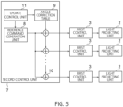
- FIG. 5 is a block diagram illustrating an example of an internal configuration of the second control unit 7.
- the second control unit 7 of FIG. 5 includes a reference command generation unit 8, an angle correction table 9, a plurality of adders 10, and an update control unit 11.
- the reference command generation unit 8 generates a reference command signal commonly provided to all the light projecting units 2.
- the reference command signal is not necessarily one type.
- the reference command generation unit 8 may generate any of a plurality of types of reference command signals.
- the reference command signal generated by the reference command generation unit 8 is input to the plurality of adders 10.
- the angle correction table 9 stores an angle correction signal for correcting the reference command signal for each of the plurality of light projecting units 2.
- the angle correction table 9 stores the angle correction signal corresponding to each of the plurality of light projecting units 2 for each reference command signal.
- the angle correction signal includes an offset of an angle intended for each light projecting unit 2 and an angle error of each light projecting unit 2 due to installation, manufacturing, and the like.
- a laser may be emitted from each light projecting unit 2 in advance, and the angle may be measured by a light receiving device, a photosensitive paper, or the like (not illustrated in FIG. 5 ).
- the angle correction table 9 may store a plurality of sets of correspondences between the reference command signals and the plurality of angle correction signals, and the plurality of angle correction signals may be different for each set.
- the second control unit 7 selects one set from the plurality of sets stored in the angle correction table 9, reads the corresponding angle correction signal from the angle correction table 9 for each of the plurality of light projecting units 2 based on the correspondence relationship of the selected set, and loads the reference command signal, thereby generating the angle command signal.
- FIG. 6A is a diagram showing a first specific example of the plurality of types of reference command signals.
- the reference command signal in the first specific example is a signal instructing continuous or stepwise change of the emission direction according to time for each cycle.
- the reference command signal is an analog value or a digital value, and may be a voltage signal or a current signal.
- the angle correction table 9 stores, for example, an angle correction signal for making the emission direction parallel for each of the plurality of light projecting units 2.
- the angle correction table 9 sets the angle correction signal of the emission direction of one of the two light projecting units 2 to 0 degrees and sets the angle correction signal of the emission direction of the other to -1 degrees.
- the emission directions of the optical signals emitted from the two light projecting units 2 can be made parallel.
- FIG. 6B is a diagram showing a second specific example of the plurality of types of reference command signals.
- the reference command signal in the second specific example is emitted a plurality of times at predetermined time intervals, and becomes a pulse train signal as shown in FIG. 6B .
- the emission direction of each reference command signal is changed by an angle corresponding to the number of times of emission of the optical signal. For example, when the emission direction of the optical signal is changed by m degrees every time the reference command signal is emitted, the emission direction of the n-th reference command signal is changed by m ⁇ n degrees as compared with the first reference command signal. As shown in FIG. 6B , the emission direction is periodically changed in a range of 0 to 360 degrees.
- the angle correction table 9 in the second specific example stores, for example, the angle correction signals such that the emission directions of the optical signals emitted from the plurality of light projecting units 2 are parallel.
- the plurality of types of reference command signals and the angle correction signals stored in the angle correction table 9 are not necessarily limited to the first specific example and the second specific example described above.
- the plurality of adders 10 are provided in association with the plurality of first control units 3. Each of the plurality of adders 10 adds the reference command signal and the corresponding angle correction signal read from the angle correction table 9 to generate a corresponding angle command signal for the first control unit 3.
- the angle correction signal stored in the angle correction table 9 may be updated as necessary.
- the update control unit 11 in the second control unit 7 updates the angle correction signal stored in the angle correction table 9.
- the update control unit 11 and the reference command generation unit 8 may be integrated.
- the second control unit 7 is not necessarily configured as illustrated in FIG. 5 .
- the angle command signals for the plurality of first control units 3 may be directly generated by the second control unit 7 and supplied to the corresponding first control units 3.
- the configuration in which the emission direction of the optical signal emitted from each of the plurality of light projecting units 2 can be individually controlled has been described, but the plurality of light projecting units 2 may be integrated to collectively scan the plurality of optical signals emitted from the plurality of light projecting units 2 in the one-dimensional direction or the two-dimensional direction.
- FIG. 7 is a block diagram illustrating a schematic configuration of a light projecting apparatus 1b in which a scanning control unit 12 is added to the configuration of FIG. 4
- FIG. 8 is a perspective view of the light projecting apparatus 1b of FIG. 7
- the scanning control unit 12 periodically scans the optical signals emitted from the plurality of light projecting units 2 integrally in a one-dimensional direction or a two-dimensional direction.
- the scanning control unit 12 may cause the light projecting apparatus 1b to periodically scan at least one of the horizontal direction X and the vertical direction Y for each housing thereof.
- the emission directions of the plurality of optical signals emitted from the plurality of light projecting units 2 can be individually controlled by the corresponding first control units 3, and the emission directions of the plurality of optical signals can be integrally controlled by the scanning control unit 12.
- the light projecting apparatuses 1, 1a, and 1b according to the first example include the plurality of light projecting units 2 and the plurality of first control units 3, and the emission direction and the emission timing of the optical signal emitted from each of the plurality of light projecting units 2 are controlled by the corresponding first control unit 3.
- the emission direction and the emission timing of the optical signal emitted from each of the plurality of light projecting units 2 can be individually and arbitrarily adjusted, and the plurality of optical signals emitted from the plurality of light projecting units 2 can be used for various applications.
- the second control unit 7 that controls the plurality of first control units 3 is provided and the angle command signals are supplied from the second control unit 7 to the plurality of first control units 3, it is possible to realize the reconfigurable light projecting apparatuses 1, 1a, and 1b in which the emission directions and the emission timings of the optical signals from the plurality of light projecting units 2 are changed by updating the angle command signals as necessary.
- Light projecting apparatuses 1a and 1b according to a second example have a block configuration similar to that in FIGS. 4 to 7 .
- the second control unit 7 controls the plurality of light projecting units 2 so that optical signals traveling substantially in parallel are emitted from the plurality of light projecting units 2.
- FIG. 9 is a diagram schematically illustrating beam shapes of optical signals emitted from the plurality of light projecting units 2.
- the plurality of optical signals emitted from the plurality of light projecting units 2 travel in substantially parallel directions.
- the emission direction of the optical signal emitted from each of the plurality of light projecting units 2 is controlled by the corresponding first control unit 3.
- an angle command signal is supplied from the second control unit 7 to each of the plurality of first control units 3 corresponding to the plurality of light projecting units 2.
- Each of the plurality of first control units 3 controls the emission direction of the optical signal emitted from the corresponding light projecting unit 2 based on the corresponding angle command signal.
- the corresponding first control unit 3 controls the emission direction of the optical signal emitted from the corresponding light projecting unit 2 by the angle command signal from the second control unit 7, and the plurality of optical signals emitted from the plurality of light projecting units 2 are made substantially parallel.
- FIGS. 10A and 10B are diagrams schematically illustrating the beam width of the optical signal emitted from each light projecting unit 2
- FIG. 10A illustrates a change in the beam width in the horizontal direction
- FIG. 10B illustrates a change in the beam width in the vertical direction.
- the beam width in the horizontal direction hardly changes even when the distance changes as illustrated in FIG. 10A , whereas the beam width in the vertical direction greatly changes according to the distance as illustrated in FIG. 10B . More specifically, the beam width in the vertical direction increases as the distance increases.
- a region in which the optical signals emitted from the plurality of light projecting units 2 overlap each other in the vertical direction is generated at a place distant from the light projecting apparatuses 1a and 1b.
- the light intensity is higher than that of a single optical signal.
- the plurality of optical signals are emitted from the plurality of light projecting units 2 in the substantially parallel direction, and the plurality of optical signals emitted from the plurality of light projecting units 2 partially overlap each other in the vertical direction, so that the light intensity at a distant place can be increased.
- FIG. 10B when the interval between the plurality of light projecting units 2 arranged in the vertical direction changes, the range in which the plurality of optical signals overlap each other in the vertical direction at a distant place changes. If each laser beam does not spread so much and overlaps at a short distance where the laser intensity is strong, the overlapping portion may not be eye safe compliant. Therefore, it is desirable to adjust the interval between the plurality of light projecting units 2 arranged in the vertical direction so that the overlapping range can conform to the eye safe standard.
- the plurality of light projecting units 2 may emit optical signals at substantially the same emission timing.
- the optical signal is repeatedly emitted at predetermined time intervals, the reflected optical signal from the object is repeatedly received, and the distance to the object is measured based on the light reception result.
- the operation of emitting the optical signals from the plurality of light projecting units 2 at substantially the same timing is repeatedly performed at predetermined time intervals, and the reflected optical signal from the object is repeatedly received to measure the distance to the object.
- Light projecting apparatuses 1a and 1b according to a third example classify the plurality of light projecting units 2 into a plurality of light projecting groups.
- the plurality of light projecting units 2 emit the plurality of optical signals in substantially the same emission direction has been described, but in the third example, the plurality of light projecting units 2 are classified into two or more light projecting groups, and the emission direction of the optical signal is individually controlled for each light projecting group.
- N is an integer of 2 or more
- light projecting units 2 are classified into M (2 ⁇ M ⁇ N) light projecting groups, and the light projecting units 2 belonging to the same light projecting group emit optical signals in the same emission direction.
- the light emission ranges of the light projecting units 2 belonging to different light projecting groups do not overlap each other or only partially overlap each other.
- the light emission ranges of the light projecting apparatuses 1a and 1b including the plurality of light projecting units 2 can be wider than the light emission range of the single light projecting unit 2.
- the light emission range of the light projecting unit 2 is narrowed because the drive range of the MEMS mirror is narrowed. Therefore, by providing a plurality of MEMS mirrors, the light emission range as a whole can be expanded.
- FIG. 11 is a diagram schematically illustrating characteristic portions of the light projecting apparatuses 1a and 1b according to the third example.
- FIG. 11 illustrates an example in which a plurality of (for example, four) light projecting units 2 are classified into three light projecting groups (hereinafter, first to third light projecting groups) 2-1, 2-2, and 2-3, and the emission direction of the optical signal is individually controlled for each light projecting group.
- first to third light projecting groups hereinafter, first to third light projecting groups
- the light projecting unit 2 belonging to the first light projecting group 2-1 scans the optical signal in a first light emission range OR1.
- the light projecting unit 2 belonging to the second light projecting group 2-2 scans the optical signal in a second light emission range OR2.
- the light projecting unit 2 belonging to the third light projecting group 2-3 scans the optical signal in a third light emission range OR3.
- FIG. 11 illustrates an example in which the first light emission range OR1, the second light emission range OR2, and the third light emission range OR3 do not overlap each other, but may partially overlap each other.
- the emission direction of the optical signal emitted from the light projecting unit 2 belonging to the first light projecting group 2-1, the emission direction of the optical signal emitted from the light projecting unit 2 belonging to the second light projecting group 2-2, and the emission direction of the optical signal emitted from the light projecting unit 2 belonging to the third light projecting group 2-3 may be completely different from each other, or may partially overlap each other.
- the light emission range of the entire light projecting apparatuses 1a and 1b can be expanded more than the light emission range of one light projecting group.
- the manner of classifying the plurality of light projecting units 2 into the plurality of light projecting groups may be determined in advance.
- the first control unit 3 corresponding to each light projecting unit 2 may grasp the emission direction and the emission timing of the optical signal.
- the second control unit 7 performs control to classify the plurality of light projecting units 2 into a plurality of light projecting groups.
- the second control unit 7 transmits, to the plurality of first control units 3, information regarding to which light projecting group the corresponding light projecting unit 2 belongs.
- the information transmitted from the second control unit 7 to the plurality of first control units 3 also includes information indicating the light emission range of each light projecting group.
- the second control unit 7 may control the timing at which the plurality of light projecting groups emit the optical signal.
- the light projecting units 2 belonging to the first to third light projecting groups 2-1 to 2-3 may emit optical signals at substantially the same timing, or may emit optical signals at different timings.
- the light emission range can be expanded as compared with the case where the light emission ranges of the plurality of light projecting units 2 are aligned. Therefore, in a case where the light projecting apparatuses 1a and 1b according to the present example are applied to the distance measuring apparatus, it is possible to measure a distance to an object present in a wider range, and practicality is enhanced. In addition, by changing which light projecting unit 2 is classified into which light projecting group as necessary, it is possible to realize the reconfigurable light projecting apparatuses 1a and 1b.
- the light projecting apparatuses 1, 1a, and 1b according to the first to third examples can be applied to the distance measuring apparatus.
- FIG. 12 is a block diagram illustrating a schematic configuration of a distance measuring apparatus 21 incorporating the light projecting apparatuses 1, 1a, and 1b according to any one of the first to third examples.
- the distance measuring apparatus 21 of FIG. 12 includes the light projecting apparatuses 1, 1a, and 1b according to any one of the first to third examples, a light receiving device 22, and a distance measurement unit 23.
- the light receiving device 22 receives a reflected optical signal obtained by reflecting a plurality of optical signals emitted from the light projecting apparatuses 1, 1a, and 1b by an object.
- the light receiving device 22 may include a light receiving module in which a plurality of light receiving elements are two-dimensionally arranged.
- the light receiving element may be a single photo avalanche diode (SPAD). Since the SPAD can detect one photon, it is possible to detect a weak reflected optical signal from a distant object.
- SPAD photo avalanche diode
- the distance measuring apparatus 21 measures the distance by, for example, a direct time of flight (dToF) method.
- dToF direct time of flight
- the distance to the object is measured based on the time difference between the timing at which the light projecting apparatuses 1, 1a, and 1b emit the optical signal and the timing at which the light receiving device 22 receives the reflected optical signal.
- the second control unit 7 in the distance measuring apparatus 21 of FIG. 12 may supply the angle command signals to the plurality of first control units 3 so that the plurality of light projecting units 2 emit the optical signal in substantially the same emission direction, or may supply the angle command signal to the corresponding first control unit 3 for each light projecting group obtained by classifying the plurality of light projecting units 2 into a plurality of light projecting groups.
- each light projecting unit 2 in the distance measuring apparatus 21 repeatedly emits the optical signal while scanning the optical signal in the two-dimensional direction within the predetermined light emission range, the light receiving device 22 continuously receives the reflected optical signal, and the distance measurement unit 23 measures the distance to the object based on the light reception result.
- the cycles in which the light projecting units 2 scan the optical signal within the light emission range are not necessarily the same.
- each light projecting unit 2 emits the optical signal at a predetermined time interval (for example, a time interval determined by the eye safe reference), as the time during which each light projecting unit 2 scans the optical signal in the light emission range is longer, the number of optical signals emitted from each light projecting unit 2 increases while the light emission range is scanned, and the presence or absence of an object in the light emission range and the shape of the object can be detected more accurately.
- a predetermined time interval for example, a time interval determined by the eye safe reference
- FIG. 13 is a block diagram of a distance measuring apparatus 21a in which an object detecting unit 24 and a scanning speed adjusting unit 25 are added to the configuration of FIG. 12 .
- the object detecting unit 24 detects an object present in the light emission range while the plurality of light projecting units 2 scan the optical signals in the light emission range.
- the scanning speed adjusting unit 25 adjusts the length of the cycle in which the optical signal scans the light emission range. More specifically, the scanning speed adjusting unit 25 makes the scanning speed when the optical signal is scanned within the range where the object detected by the object detecting unit is present slower than the scanning speed when the optical signal is scanned outside the range. It is assumed that each light projecting unit 2 emits an optical signal at a constant time interval.
- the scanning speed adjusting unit 25 sets the length of the cycle in which the optical signal scans the light emission range to a first scanning cycle, and then starts a distance measuring operation.
- the object detecting unit 24 detects whether or not the light receiving device 22 has received the reflected optical signal from the object while the light projecting apparatuses 1, 1a, and 1b are scanning the light emission range with the first scanning cycle.
- the object detecting unit 24 determines that the reflected optical signal has been received.
- the object detecting unit 24 detects all objects present in the entire light emission range.
- the scanning speed adjusting unit 25 decreases the scanning speed of the optical signal when scanning the vicinity of the detection position of the object in the light emission range. As a result, more optical signals can be emitted in the vicinity of the detection position of the object in the light emission range, and the depth shape of the object can be detected more accurately.
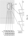
- FIG. 14 illustrates an example in which one object (vehicle in the example of FIG. 14 ) 26 is present in the lower right region in the light emission range.
- Each square in the light emission range in FIG. 14 indicates the emission timing of the optical signal.
- the size of the square is small, indicating that more optical signals are radiated to the vicinity of the detection position of the object 26 to more finely detect the depth shape of the object 26.
- a timing chart in a case where the light emission range is scanned twice is shown.
- a scanning cycle at a first time is referred to as a first scanning cycle
- a scanning cycle at a second time is referred to as a second scanning cycle.
- the horizontal axis represents time
- the vertical axis represents a scanning position within the light emission range.
- the vertical axis may be a scanning angle.
- time t1 to time t4 are the first scanning cycle
- time t4 to time t9 are the second scanning cycle.
- a period from time t2 to time t3 in the first scanning cycle is a period for scanning a region where the vehicle is present in the light emission range. Since the signal level of the light reception signal received by the light receiving device 22 increases in this period, the object detecting unit 24 detects the object 26.
- the optical signal is initially scanned at the same scanning speed as in the first scanning cycle.
- the scanning speed adjusting unit 25 decreases the scanning speed of the optical signal.
- the scanning position changes at the same inclination as that at time t1 to time t4 near the position of the object 26, whereas, at time t5 to time t8, the change in the scanning position per unit time becomes smaller.
- the object 26 is detected in a period from time t6 to time t7.
- a period t6 to t7 during which the object 26 is detected in the second scanning cycle is longer than a period t2 to t3 during which the object 26 is detected in the first scanning cycle. Therefore, in the period from time t6 to time t7, the object 26 can be irradiated with more optical signals than during the period from time t2 to time t3.
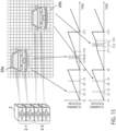
- FIG. 15 is a diagram illustrating an example in which a plurality of (two in the example of FIG. 15 ) objects 26 are detected in the light emission range.
- the plurality of light projecting units 2 are classified into a plurality of light projecting groups according to the number of detected objects 26.
- the plurality of light projecting units 2 are classified into two light projecting groups. The number of the light projecting units 2 belonging to each light projecting group is freely selectable.
- time t1 to time t6 are the first scanning cycle
- time t6 to time t15 are the second scanning cycle.
- the first scanning cycle the entire region in the light emission range is scanned at a constant scanning speed.
- the object detecting unit 24 detects two objects 26 in the light emission range. As described above, the object detecting unit 24 detects the object 26 when the signal level of the light reception signal of the light receiving device 22 exceeds the predetermined threshold.
- the object detecting unit 24 detects two objects 26 at time t2 to time t3 and time t4 to time t5 in the first scanning cycle.
- the first control unit 3 classifies the plurality of light projecting units 2 into, for example, two light projecting groups (the first light projecting group 2-1 and the second light projecting group 2-2) since two objects (a first object and a second object) 26a and 26b are detected by the object detecting unit 24, and decreases the scanning speed when the two light projecting units 2 belonging to the first light projecting group 2-1 scan the vicinity of the position of the first object 26a to more accurately detect the depth shape of the first object 26a.
- the scanning speed is decreased when the two light projecting units 2 belonging to the second light projecting group 2-2 scan the vicinity of the position of the second object 26b to more accurately detect the depth shape of the second object 26b.
- the first light projecting group 2-1 scans the optical signal in the periods from time t6 to time t7 and from time t10 to time t15 in the second scanning cycle in the same cycle as the first scanning cycle. In the period from time t7 to time t10, the scanning speed of the optical signal is reduced because the position is near the position of the object 26. The object 26 is detected in a period from time t8 to time t9.
- the second light projecting group 2-2 scans the optical signal in the periods from time t6 to time t11 and from time t14 to time t15 in the second scanning cycle in the same cycle as the first scanning cycle. In the period from time t11 to time t14, the scanning speed of the optical signal is reduced because the position is near the position of the object 26. The object 26 is detected in a period from time t12 to time t13.
- the depth shape of the object 26 is detected by slowing the scanning speed by a separate light projecting group for each object 26 detected in the light emission range, the depth shape of each object 26 can be accurately detected without making the second scanning cycle longer than the first scanning cycle.
- the light projecting apparatuses 1, 1a, and 1b according to the first to third examples are applied to the distance measuring apparatuses 21 and 21a, an object 26 in a wide range can be accurately detected.
- the scanning speed is reduced when the vicinity of the position of the detected object 26 is scanned with an optical signal. As a result, the depth shape of the object 26 can be detected more accurately.
- the plurality of light projecting units 2 are classified into a plurality of light projecting groups in accordance with the number of detected objects 26, and the corresponding objects 26 can be detected at a slow scanning speed in each light projecting group, so that the depth shapes of the plurality of objects 26 in the light emission range can be accurately detected.
Landscapes
- Engineering & Computer Science (AREA)
- Physics & Mathematics (AREA)
- Computer Networks & Wireless Communication (AREA)
- General Physics & Mathematics (AREA)
- Radar, Positioning & Navigation (AREA)
- Remote Sensing (AREA)
- Electromagnetism (AREA)
- Measurement Of Optical Distance (AREA)
- Optical Radar Systems And Details Thereof (AREA)
Applications Claiming Priority (1)
| Application Number | Priority Date | Filing Date | Title |
|---|---|---|---|
| JP2021182794A JP2023070546A (ja) | 2021-11-09 | 2021-11-09 | 投光装置、測距装置、及びレーザ光の投光制御方法 |
Publications (2)
| Publication Number | Publication Date |
|---|---|
| EP4177631A2 true EP4177631A2 (de) | 2023-05-10 |
| EP4177631A3 EP4177631A3 (de) | 2023-07-12 |
Family
ID=83271053
Family Applications (1)
| Application Number | Title | Priority Date | Filing Date |
|---|---|---|---|
| EP22193426.8A Pending EP4177631A3 (de) | 2021-11-09 | 2022-09-01 | Lichtprojektionsvorrichtung, abstandsmessvorrichtung und lichtprojektionssteuerungsverfahren für laserlicht |
Country Status (3)
| Country | Link |
|---|---|
| US (1) | US20230146289A1 (de) |
| EP (1) | EP4177631A3 (de) |
| JP (2) | JP2023070546A (de) |
Families Citing this family (1)
| Publication number | Priority date | Publication date | Assignee | Title |
|---|---|---|---|---|
| CN116359886B (zh) * | 2021-12-27 | 2023-12-29 | 深圳市速腾聚创科技有限公司 | 一种雷达控制方法、终端设备及计算机可读存储介质 |
Family Cites Families (7)
| Publication number | Priority date | Publication date | Assignee | Title |
|---|---|---|---|---|
| US7936448B2 (en) * | 2006-01-27 | 2011-05-03 | Lightwire Inc. | LIDAR system utilizing SOI-based opto-electronic components |
| WO2017200896A2 (en) * | 2016-05-18 | 2017-11-23 | James O'keeffe | A dynamically steered lidar adapted to vehicle shape |
| DE102017002235A1 (de) * | 2017-03-08 | 2018-09-13 | Blickfeld GmbH | LIDAR-System mit flexiblen Scanparametern |
| US10613276B2 (en) * | 2018-06-08 | 2020-04-07 | Huawei Technologies Co., Ltd. | Optical scanner with optically switched paths to multiple surface or edge couplers |
| US20210293931A1 (en) * | 2018-07-26 | 2021-09-23 | Innoviz Technologies Ltd. | Lidar system having a mirror with a window |
| JP7347314B2 (ja) * | 2020-04-13 | 2023-09-20 | トヨタ自動車株式会社 | センサ及びセンサシステム |
| JP2021173663A (ja) * | 2020-04-27 | 2021-11-01 | ソニーセミコンダクタソリューションズ株式会社 | 測距装置 |
-
2021
- 2021-11-09 JP JP2021182794A patent/JP2023070546A/ja active Pending
-
2022
- 2022-09-01 EP EP22193426.8A patent/EP4177631A3/de active Pending
- 2022-09-08 US US17/930,556 patent/US20230146289A1/en active Pending
-
2025
- 2025-05-29 JP JP2025090006A patent/JP2025113474A/ja active Pending
Also Published As
| Publication number | Publication date |
|---|---|
| US20230146289A1 (en) | 2023-05-11 |
| JP2023070546A (ja) | 2023-05-19 |
| EP4177631A3 (de) | 2023-07-12 |
| JP2025113474A (ja) | 2025-08-01 |
Similar Documents
| Publication | Publication Date | Title |
|---|---|---|
| JP7321553B2 (ja) | 眼安全性走査lidarシステム | |
| US11662433B2 (en) | Distance measuring apparatus, recognizing apparatus, and distance measuring method | |
| JP6547942B2 (ja) | 半導体レーザ駆動装置、光走査装置、物体検出装置及び移動体装置 | |
| WO2019165294A1 (en) | 2-dimensional steering system for lidar systems | |
| CN117321440A (zh) | 一种探测装置及其控制方法 | |
| US10132926B2 (en) | Range finder, mobile object and range-finding method | |
| KR20240033051A (ko) | 개별적으로 어드레스 가능하고 스캔 가능하며 통합 가능한 레이저 방출기를 갖는 라이다 | |
| EP4177631A2 (de) | Lichtprojektionsvorrichtung, abstandsmessvorrichtung und lichtprojektionssteuerungsverfahren für laserlicht | |
| KR20220110850A (ko) | 다중 범위 채널들을 갖는 lidar | |
| EP3775980B1 (de) | Vorrichtung und verfahren zur entfernungsabbildung | |
| US20240036197A1 (en) | Distance measuring device | |
| CN111487603B (zh) | 一种激光发射单元及其制造方法 | |
| US11236988B2 (en) | Laser distance measuring apparatus | |
| CN114415192B (zh) | 激光雷达系统及其校准方法 | |
| KR20240015629A (ko) | 불균일한 광 확대 및 펄스 에너지 변화를 갖는 주사 레이저 장치 및 방법 | |
| US20230204732A1 (en) | Distance measuring device | |
| US20210382177A1 (en) | System for monitoring surroundings of vehicle | |
| US11579258B1 (en) | Solid state pulse steering in lidar systems | |
| JP2019174126A (ja) | 測距装置 | |
| CN220584396U (zh) | 一种固态激光雷达测量系统 | |
| US20250060579A1 (en) | Optical device | |
| US20240175988A1 (en) | Sensor device, control device, control method, program, and storage medium | |
| CN119716802A (zh) | 激光雷达及其扫描方法 | |
| JP2019174125A (ja) | 測距装置 | |
| CN117434551A (zh) | 非同轴激光雷达系统及其配置方法 |
Legal Events
| Date | Code | Title | Description |
|---|---|---|---|
| PUAI | Public reference made under article 153(3) epc to a published international application that has entered the european phase |
Free format text: ORIGINAL CODE: 0009012 |
|
| STAA | Information on the status of an ep patent application or granted ep patent |
Free format text: STATUS: REQUEST FOR EXAMINATION WAS MADE |
|
| 17P | Request for examination filed |
Effective date: 20220901 |
|
| AK | Designated contracting states |
Kind code of ref document: A2 Designated state(s): AL AT BE BG CH CY CZ DE DK EE ES FI FR GB GR HR HU IE IS IT LI LT LU LV MC MK MT NL NO PL PT RO RS SE SI SK SM TR |
|
| PUAL | Search report despatched |
Free format text: ORIGINAL CODE: 0009013 |
|
| AK | Designated contracting states |
Kind code of ref document: A3 Designated state(s): AL AT BE BG CH CY CZ DE DK EE ES FI FR GB GR HR HU IE IS IT LI LT LU LV MC MK MT NL NO PL PT RO RS SE SI SK SM TR |
|
| RIC1 | Information provided on ipc code assigned before grant |
Ipc: G01S 17/08 20060101ALI20230607BHEP Ipc: G01S 7/481 20060101AFI20230607BHEP |