EP4177528B1 - Heating device with improved efficiency - Google Patents
Heating device with improved efficiency Download PDFInfo
- Publication number
- EP4177528B1 EP4177528B1 EP21206283.0A EP21206283A EP4177528B1 EP 4177528 B1 EP4177528 B1 EP 4177528B1 EP 21206283 A EP21206283 A EP 21206283A EP 4177528 B1 EP4177528 B1 EP 4177528B1
- Authority
- EP
- European Patent Office
- Prior art keywords
- air
- heat exchanger
- flue
- combustion chamber
- combustion
- Prior art date
- Legal status (The legal status is an assumption and is not a legal conclusion. Google has not performed a legal analysis and makes no representation as to the accuracy of the status listed.)
- Active
Links
- 238000010438 heat treatment Methods 0.000 title claims description 107
- 238000002485 combustion reaction Methods 0.000 claims description 180
- 239000003546 flue gas Substances 0.000 claims description 142
- UGFAIRIUMAVXCW-UHFFFAOYSA-N Carbon monoxide Chemical compound [O+]#[C-] UGFAIRIUMAVXCW-UHFFFAOYSA-N 0.000 claims description 132
- 239000008188 pellet Substances 0.000 claims description 30
- 238000012546 transfer Methods 0.000 claims description 25
- 239000002699 waste material Substances 0.000 claims description 18
- 239000000463 material Substances 0.000 claims description 14
- 239000002028 Biomass Substances 0.000 claims description 13
- 238000010304 firing Methods 0.000 claims description 9
- 238000000034 method Methods 0.000 claims description 9
- 239000002023 wood Substances 0.000 claims description 8
- 238000002156 mixing Methods 0.000 claims description 2
- 238000009423 ventilation Methods 0.000 claims 3
- 239000000446 fuel Substances 0.000 description 44
- 239000003921 oil Substances 0.000 description 23
- 239000007789 gas Substances 0.000 description 16
- 230000005855 radiation Effects 0.000 description 14
- 230000001105 regulatory effect Effects 0.000 description 7
- 239000000779 smoke Substances 0.000 description 6
- 239000000523 sample Substances 0.000 description 5
- 238000013461 design Methods 0.000 description 4
- 238000012544 monitoring process Methods 0.000 description 4
- 229920002545 silicone oil Polymers 0.000 description 4
- 238000004140 cleaning Methods 0.000 description 3
- 230000000694 effects Effects 0.000 description 3
- 239000012530 fluid Substances 0.000 description 3
- 239000000203 mixture Substances 0.000 description 3
- 238000013021 overheating Methods 0.000 description 3
- 239000004033 plastic Substances 0.000 description 3
- 229920003023 plastic Polymers 0.000 description 3
- XLYOFNOQVPJJNP-UHFFFAOYSA-N water Substances O XLYOFNOQVPJJNP-UHFFFAOYSA-N 0.000 description 3
- 241001156002 Anthonomus pomorum Species 0.000 description 2
- 229910000831 Steel Inorganic materials 0.000 description 2
- 238000006243 chemical reaction Methods 0.000 description 2
- 239000000567 combustion gas Substances 0.000 description 2
- 239000002480 mineral oil Substances 0.000 description 2
- 239000010959 steel Substances 0.000 description 2
- 239000000126 substance Substances 0.000 description 2
- 230000008093 supporting effect Effects 0.000 description 2
- 230000001960 triggered effect Effects 0.000 description 2
- 239000004698 Polyethylene Substances 0.000 description 1
- 230000005678 Seebeck effect Effects 0.000 description 1
- 206010053615 Thermal burn Diseases 0.000 description 1
- 238000010521 absorption reaction Methods 0.000 description 1
- 150000004945 aromatic hydrocarbons Chemical class 0.000 description 1
- 239000000919 ceramic Substances 0.000 description 1
- 239000003795 chemical substances by application Substances 0.000 description 1
- 239000003245 coal Substances 0.000 description 1
- 238000001816 cooling Methods 0.000 description 1
- 230000007423 decrease Effects 0.000 description 1
- 230000002950 deficient Effects 0.000 description 1
- 230000001419 dependent effect Effects 0.000 description 1
- 238000011161 development Methods 0.000 description 1
- 230000018109 developmental process Effects 0.000 description 1
- 239000003344 environmental pollutant Substances 0.000 description 1
- 238000000605 extraction Methods 0.000 description 1
- 239000008187 granular material Substances 0.000 description 1
- 230000005484 gravity Effects 0.000 description 1
- 238000009413 insulation Methods 0.000 description 1
- 238000005259 measurement Methods 0.000 description 1
- 238000012806 monitoring device Methods 0.000 description 1
- 231100000719 pollutant Toxicity 0.000 description 1
- -1 polyethylene Polymers 0.000 description 1
- 229920000573 polyethylene Polymers 0.000 description 1
- 238000011084 recovery Methods 0.000 description 1
- 230000000630 rising effect Effects 0.000 description 1
- 239000007787 solid Substances 0.000 description 1
- 125000006850 spacer group Chemical group 0.000 description 1
- 238000005979 thermal decomposition reaction Methods 0.000 description 1
- 238000002604 ultrasonography Methods 0.000 description 1
- 238000003466 welding Methods 0.000 description 1
Images
Classifications
-
- F—MECHANICAL ENGINEERING; LIGHTING; HEATING; WEAPONS; BLASTING
- F24—HEATING; RANGES; VENTILATING
- F24B—DOMESTIC STOVES OR RANGES FOR SOLID FUELS; IMPLEMENTS FOR USE IN CONNECTION WITH STOVES OR RANGES
- F24B5/00—Combustion-air or flue-gas circulation in or around stoves or ranges
- F24B5/02—Combustion-air or flue-gas circulation in or around stoves or ranges in or around stoves
- F24B5/021—Combustion-air or flue-gas circulation in or around stoves or ranges in or around stoves combustion-air circulation
- F24B5/023—Supply of primary air for combustion
-
- F—MECHANICAL ENGINEERING; LIGHTING; HEATING; WEAPONS; BLASTING
- F24—HEATING; RANGES; VENTILATING
- F24H—FLUID HEATERS, e.g. WATER OR AIR HEATERS, HAVING HEAT-GENERATING MEANS, e.g. HEAT PUMPS, IN GENERAL
- F24H9/00—Details
- F24H9/0084—Combustion air preheating
-
- F—MECHANICAL ENGINEERING; LIGHTING; HEATING; WEAPONS; BLASTING
- F23—COMBUSTION APPARATUS; COMBUSTION PROCESSES
- F23B—METHODS OR APPARATUS FOR COMBUSTION USING ONLY SOLID FUEL
- F23B80/00—Combustion apparatus characterised by means creating a distinct flow path for flue gases or for non-combusted gases given off by the fuel
- F23B80/04—Combustion apparatus characterised by means creating a distinct flow path for flue gases or for non-combusted gases given off by the fuel by means for guiding the flow of flue gases, e.g. baffles
-
- F—MECHANICAL ENGINEERING; LIGHTING; HEATING; WEAPONS; BLASTING
- F23—COMBUSTION APPARATUS; COMBUSTION PROCESSES
- F23B—METHODS OR APPARATUS FOR COMBUSTION USING ONLY SOLID FUEL
- F23B40/00—Combustion apparatus with driven means for feeding fuel into the combustion chamber
-
- F—MECHANICAL ENGINEERING; LIGHTING; HEATING; WEAPONS; BLASTING
- F23—COMBUSTION APPARATUS; COMBUSTION PROCESSES
- F23B—METHODS OR APPARATUS FOR COMBUSTION USING ONLY SOLID FUEL
- F23B50/00—Combustion apparatus in which the fuel is fed into or through the combustion zone by gravity, e.g. from a fuel storage situated above the combustion zone
- F23B50/12—Combustion apparatus in which the fuel is fed into or through the combustion zone by gravity, e.g. from a fuel storage situated above the combustion zone the fuel being fed to the combustion zone by free fall or by sliding along inclined surfaces, e.g. from a conveyor terminating above the fuel bed
-
- F—MECHANICAL ENGINEERING; LIGHTING; HEATING; WEAPONS; BLASTING
- F23—COMBUSTION APPARATUS; COMBUSTION PROCESSES
- F23G—CREMATION FURNACES; CONSUMING WASTE PRODUCTS BY COMBUSTION
- F23G7/00—Incinerators or other apparatus for consuming industrial waste, e.g. chemicals
- F23G7/10—Incinerators or other apparatus for consuming industrial waste, e.g. chemicals of field or garden waste or biomasses
-
- F—MECHANICAL ENGINEERING; LIGHTING; HEATING; WEAPONS; BLASTING
- F23—COMBUSTION APPARATUS; COMBUSTION PROCESSES
- F23J—REMOVAL OR TREATMENT OF COMBUSTION PRODUCTS OR COMBUSTION RESIDUES; FLUES
- F23J1/00—Removing ash, clinker, or slag from combustion chambers
- F23J1/06—Mechanically-operated devices, e.g. clinker pushers
-
- F—MECHANICAL ENGINEERING; LIGHTING; HEATING; WEAPONS; BLASTING
- F23—COMBUSTION APPARATUS; COMBUSTION PROCESSES
- F23L—SUPPLYING AIR OR NON-COMBUSTIBLE LIQUIDS OR GASES TO COMBUSTION APPARATUS IN GENERAL ; VALVES OR DAMPERS SPECIALLY ADAPTED FOR CONTROLLING AIR SUPPLY OR DRAUGHT IN COMBUSTION APPARATUS; INDUCING DRAUGHT IN COMBUSTION APPARATUS; TOPS FOR CHIMNEYS OR VENTILATING SHAFTS; TERMINALS FOR FLUES
- F23L1/00—Passages or apertures for delivering primary air for combustion
- F23L1/02—Passages or apertures for delivering primary air for combustion by discharging the air below the fire
-
- F—MECHANICAL ENGINEERING; LIGHTING; HEATING; WEAPONS; BLASTING
- F23—COMBUSTION APPARATUS; COMBUSTION PROCESSES
- F23L—SUPPLYING AIR OR NON-COMBUSTIBLE LIQUIDS OR GASES TO COMBUSTION APPARATUS IN GENERAL ; VALVES OR DAMPERS SPECIALLY ADAPTED FOR CONTROLLING AIR SUPPLY OR DRAUGHT IN COMBUSTION APPARATUS; INDUCING DRAUGHT IN COMBUSTION APPARATUS; TOPS FOR CHIMNEYS OR VENTILATING SHAFTS; TERMINALS FOR FLUES
- F23L15/00—Heating of air supplied for combustion
- F23L15/04—Arrangements of recuperators
-
- F—MECHANICAL ENGINEERING; LIGHTING; HEATING; WEAPONS; BLASTING
- F23—COMBUSTION APPARATUS; COMBUSTION PROCESSES
- F23L—SUPPLYING AIR OR NON-COMBUSTIBLE LIQUIDS OR GASES TO COMBUSTION APPARATUS IN GENERAL ; VALVES OR DAMPERS SPECIALLY ADAPTED FOR CONTROLLING AIR SUPPLY OR DRAUGHT IN COMBUSTION APPARATUS; INDUCING DRAUGHT IN COMBUSTION APPARATUS; TOPS FOR CHIMNEYS OR VENTILATING SHAFTS; TERMINALS FOR FLUES
- F23L17/00—Inducing draught; Tops for chimneys or ventilating shafts; Terminals for flues
- F23L17/005—Inducing draught; Tops for chimneys or ventilating shafts; Terminals for flues using fans
-
- F—MECHANICAL ENGINEERING; LIGHTING; HEATING; WEAPONS; BLASTING
- F24—HEATING; RANGES; VENTILATING
- F24B—DOMESTIC STOVES OR RANGES FOR SOLID FUELS; IMPLEMENTS FOR USE IN CONNECTION WITH STOVES OR RANGES
- F24B1/00—Stoves or ranges
- F24B1/02—Closed stoves
- F24B1/024—Closed stoves for pulverulent fuels
-
- F—MECHANICAL ENGINEERING; LIGHTING; HEATING; WEAPONS; BLASTING
- F24—HEATING; RANGES; VENTILATING
- F24B—DOMESTIC STOVES OR RANGES FOR SOLID FUELS; IMPLEMENTS FOR USE IN CONNECTION WITH STOVES OR RANGES
- F24B1/00—Stoves or ranges
- F24B1/02—Closed stoves
- F24B1/026—Closed stoves with several combustion zones
-
- F—MECHANICAL ENGINEERING; LIGHTING; HEATING; WEAPONS; BLASTING
- F24—HEATING; RANGES; VENTILATING
- F24B—DOMESTIC STOVES OR RANGES FOR SOLID FUELS; IMPLEMENTS FOR USE IN CONNECTION WITH STOVES OR RANGES
- F24B1/00—Stoves or ranges
- F24B1/18—Stoves with open fires, e.g. fireplaces
- F24B1/185—Stoves with open fires, e.g. fireplaces with air-handling means, heat exchange means, or additional provisions for convection heating ; Controlling combustion
-
- F—MECHANICAL ENGINEERING; LIGHTING; HEATING; WEAPONS; BLASTING
- F24—HEATING; RANGES; VENTILATING
- F24B—DOMESTIC STOVES OR RANGES FOR SOLID FUELS; IMPLEMENTS FOR USE IN CONNECTION WITH STOVES OR RANGES
- F24B13/00—Details solely applicable to stoves or ranges burning solid fuels
- F24B13/006—Arrangements for cleaning, e.g. soot removal; Ash removal
-
- F—MECHANICAL ENGINEERING; LIGHTING; HEATING; WEAPONS; BLASTING
- F24—HEATING; RANGES; VENTILATING
- F24B—DOMESTIC STOVES OR RANGES FOR SOLID FUELS; IMPLEMENTS FOR USE IN CONNECTION WITH STOVES OR RANGES
- F24B13/00—Details solely applicable to stoves or ranges burning solid fuels
- F24B13/04—Arrangements for feeding solid fuel, e.g. hoppers
-
- F—MECHANICAL ENGINEERING; LIGHTING; HEATING; WEAPONS; BLASTING
- F24—HEATING; RANGES; VENTILATING
- F24B—DOMESTIC STOVES OR RANGES FOR SOLID FUELS; IMPLEMENTS FOR USE IN CONNECTION WITH STOVES OR RANGES
- F24B5/00—Combustion-air or flue-gas circulation in or around stoves or ranges
- F24B5/02—Combustion-air or flue-gas circulation in or around stoves or ranges in or around stoves
- F24B5/021—Combustion-air or flue-gas circulation in or around stoves or ranges in or around stoves combustion-air circulation
- F24B5/025—Supply of secondary air for completing combustion of fuel
-
- F—MECHANICAL ENGINEERING; LIGHTING; HEATING; WEAPONS; BLASTING
- F24—HEATING; RANGES; VENTILATING
- F24B—DOMESTIC STOVES OR RANGES FOR SOLID FUELS; IMPLEMENTS FOR USE IN CONNECTION WITH STOVES OR RANGES
- F24B7/00—Stoves, ranges or flue-gas ducts, with additional provisions for convection heating
- F24B7/02—Stoves, ranges or flue-gas ducts, with additional provisions for convection heating with external air ducts
- F24B7/025—Stoves, ranges or flue-gas ducts, with additional provisions for convection heating with external air ducts with forced circulation
-
- F—MECHANICAL ENGINEERING; LIGHTING; HEATING; WEAPONS; BLASTING
- F24—HEATING; RANGES; VENTILATING
- F24B—DOMESTIC STOVES OR RANGES FOR SOLID FUELS; IMPLEMENTS FOR USE IN CONNECTION WITH STOVES OR RANGES
- F24B7/00—Stoves, ranges or flue-gas ducts, with additional provisions for convection heating
- F24B7/04—Stoves, ranges or flue-gas ducts, with additional provisions for convection heating with internal air ducts
- F24B7/045—Stoves, ranges or flue-gas ducts, with additional provisions for convection heating with internal air ducts with forced circulation
-
- F—MECHANICAL ENGINEERING; LIGHTING; HEATING; WEAPONS; BLASTING
- F24—HEATING; RANGES; VENTILATING
- F24D—DOMESTIC- OR SPACE-HEATING SYSTEMS, e.g. CENTRAL HEATING SYSTEMS; DOMESTIC HOT-WATER SUPPLY SYSTEMS; ELEMENTS OR COMPONENTS THEREFOR
- F24D12/00—Other central heating systems
- F24D12/02—Other central heating systems having more than one heat source
-
- F—MECHANICAL ENGINEERING; LIGHTING; HEATING; WEAPONS; BLASTING
- F24—HEATING; RANGES; VENTILATING
- F24D—DOMESTIC- OR SPACE-HEATING SYSTEMS, e.g. CENTRAL HEATING SYSTEMS; DOMESTIC HOT-WATER SUPPLY SYSTEMS; ELEMENTS OR COMPONENTS THEREFOR
- F24D5/00—Hot-air central heating systems; Exhaust gas central heating systems
-
- F—MECHANICAL ENGINEERING; LIGHTING; HEATING; WEAPONS; BLASTING
- F24—HEATING; RANGES; VENTILATING
- F24D—DOMESTIC- OR SPACE-HEATING SYSTEMS, e.g. CENTRAL HEATING SYSTEMS; DOMESTIC HOT-WATER SUPPLY SYSTEMS; ELEMENTS OR COMPONENTS THEREFOR
- F24D7/00—Central heating systems employing heat-transfer fluids not covered by groups F24D1/00 - F24D5/00, e.g. oil, salt or gas
-
- F—MECHANICAL ENGINEERING; LIGHTING; HEATING; WEAPONS; BLASTING
- F24—HEATING; RANGES; VENTILATING
- F24H—FLUID HEATERS, e.g. WATER OR AIR HEATERS, HAVING HEAT-GENERATING MEANS, e.g. HEAT PUMPS, IN GENERAL
- F24H1/00—Water heaters, e.g. boilers, continuous-flow heaters or water-storage heaters
- F24H1/06—Portable or mobile, e.g. collapsible
-
- F—MECHANICAL ENGINEERING; LIGHTING; HEATING; WEAPONS; BLASTING
- F24—HEATING; RANGES; VENTILATING
- F24H—FLUID HEATERS, e.g. WATER OR AIR HEATERS, HAVING HEAT-GENERATING MEANS, e.g. HEAT PUMPS, IN GENERAL
- F24H3/00—Air heaters
- F24H3/02—Air heaters with forced circulation
- F24H3/027—Air heaters with forced circulation using solid fuel
-
- F—MECHANICAL ENGINEERING; LIGHTING; HEATING; WEAPONS; BLASTING
- F24—HEATING; RANGES; VENTILATING
- F24H—FLUID HEATERS, e.g. WATER OR AIR HEATERS, HAVING HEAT-GENERATING MEANS, e.g. HEAT PUMPS, IN GENERAL
- F24H3/00—Air heaters
- F24H3/02—Air heaters with forced circulation
- F24H3/06—Air heaters with forced circulation the air being kept separate from the heating medium, e.g. using forced circulation of air over radiators
- F24H3/067—Air heaters with forced circulation the air being kept separate from the heating medium, e.g. using forced circulation of air over radiators using solid fuel
-
- F—MECHANICAL ENGINEERING; LIGHTING; HEATING; WEAPONS; BLASTING
- F24—HEATING; RANGES; VENTILATING
- F24H—FLUID HEATERS, e.g. WATER OR AIR HEATERS, HAVING HEAT-GENERATING MEANS, e.g. HEAT PUMPS, IN GENERAL
- F24H9/00—Details
- F24H9/0052—Details for air heaters
- F24H9/0073—Arrangement or mounting of means for forcing the circulation of air
-
- F—MECHANICAL ENGINEERING; LIGHTING; HEATING; WEAPONS; BLASTING
- F24—HEATING; RANGES; VENTILATING
- F24H—FLUID HEATERS, e.g. WATER OR AIR HEATERS, HAVING HEAT-GENERATING MEANS, e.g. HEAT PUMPS, IN GENERAL
- F24H9/00—Details
- F24H9/0084—Combustion air preheating
- F24H9/0089—Combustion air preheating by double wall boiler mantle
-
- F—MECHANICAL ENGINEERING; LIGHTING; HEATING; WEAPONS; BLASTING
- F24—HEATING; RANGES; VENTILATING
- F24H—FLUID HEATERS, e.g. WATER OR AIR HEATERS, HAVING HEAT-GENERATING MEANS, e.g. HEAT PUMPS, IN GENERAL
- F24H9/00—Details
- F24H9/18—Arrangement or mounting of grates or heating means
- F24H9/1854—Arrangement or mounting of grates or heating means for air heaters
- F24H9/1877—Arrangement or mounting of combustion heating means, e.g. grates or burners
- F24H9/189—Arrangement or mounting of combustion heating means, e.g. grates or burners using solid fuel
-
- F—MECHANICAL ENGINEERING; LIGHTING; HEATING; WEAPONS; BLASTING
- F24—HEATING; RANGES; VENTILATING
- F24H—FLUID HEATERS, e.g. WATER OR AIR HEATERS, HAVING HEAT-GENERATING MEANS, e.g. HEAT PUMPS, IN GENERAL
- F24H9/00—Details
- F24H9/20—Arrangement or mounting of control or safety devices
- F24H9/2064—Arrangement or mounting of control or safety devices for air heaters
- F24H9/2092—Arrangement or mounting of control or safety devices for air heaters using solid fuel
-
- F—MECHANICAL ENGINEERING; LIGHTING; HEATING; WEAPONS; BLASTING
- F23—COMBUSTION APPARATUS; COMBUSTION PROCESSES
- F23G—CREMATION FURNACES; CONSUMING WASTE PRODUCTS BY COMBUSTION
- F23G2209/00—Specific waste
- F23G2209/26—Biowaste
-
- F—MECHANICAL ENGINEERING; LIGHTING; HEATING; WEAPONS; BLASTING
- F23—COMBUSTION APPARATUS; COMBUSTION PROCESSES
- F23J—REMOVAL OR TREATMENT OF COMBUSTION PRODUCTS OR COMBUSTION RESIDUES; FLUES
- F23J2700/00—Ash removal, handling and treatment means; Ash and slag handling in pulverulent fuel furnaces; Ash removal means for incinerators
- F23J2700/003—Ash removal means for incinerators
-
- F—MECHANICAL ENGINEERING; LIGHTING; HEATING; WEAPONS; BLASTING
- F24—HEATING; RANGES; VENTILATING
- F24D—DOMESTIC- OR SPACE-HEATING SYSTEMS, e.g. CENTRAL HEATING SYSTEMS; DOMESTIC HOT-WATER SUPPLY SYSTEMS; ELEMENTS OR COMPONENTS THEREFOR
- F24D2200/00—Heat sources or energy sources
- F24D2200/06—Solid fuel fired boiler
- F24D2200/065—Wood fired boilers
- F24D2200/067—Pellet fired boilers
-
- F—MECHANICAL ENGINEERING; LIGHTING; HEATING; WEAPONS; BLASTING
- F24—HEATING; RANGES; VENTILATING
- F24D—DOMESTIC- OR SPACE-HEATING SYSTEMS, e.g. CENTRAL HEATING SYSTEMS; DOMESTIC HOT-WATER SUPPLY SYSTEMS; ELEMENTS OR COMPONENTS THEREFOR
- F24D2200/00—Heat sources or energy sources
- F24D2200/16—Waste heat
- F24D2200/18—Flue gas recuperation
-
- F—MECHANICAL ENGINEERING; LIGHTING; HEATING; WEAPONS; BLASTING
- F24—HEATING; RANGES; VENTILATING
- F24H—FLUID HEATERS, e.g. WATER OR AIR HEATERS, HAVING HEAT-GENERATING MEANS, e.g. HEAT PUMPS, IN GENERAL
- F24H1/00—Water heaters, e.g. boilers, continuous-flow heaters or water-storage heaters
- F24H1/0027—Water heaters, e.g. boilers, continuous-flow heaters or water-storage heaters using fluid fuel
- F24H1/0036—Water heaters, e.g. boilers, continuous-flow heaters or water-storage heaters using fluid fuel of the sealed type
-
- F—MECHANICAL ENGINEERING; LIGHTING; HEATING; WEAPONS; BLASTING
- F24—HEATING; RANGES; VENTILATING
- F24H—FLUID HEATERS, e.g. WATER OR AIR HEATERS, HAVING HEAT-GENERATING MEANS, e.g. HEAT PUMPS, IN GENERAL
- F24H1/00—Water heaters, e.g. boilers, continuous-flow heaters or water-storage heaters
- F24H1/0063—Water heaters, e.g. boilers, continuous-flow heaters or water-storage heaters using solid fuel
-
- F—MECHANICAL ENGINEERING; LIGHTING; HEATING; WEAPONS; BLASTING
- F24—HEATING; RANGES; VENTILATING
- F24H—FLUID HEATERS, e.g. WATER OR AIR HEATERS, HAVING HEAT-GENERATING MEANS, e.g. HEAT PUMPS, IN GENERAL
- F24H2230/00—Solid fuel fired boiler
-
- Y—GENERAL TAGGING OF NEW TECHNOLOGICAL DEVELOPMENTS; GENERAL TAGGING OF CROSS-SECTIONAL TECHNOLOGIES SPANNING OVER SEVERAL SECTIONS OF THE IPC; TECHNICAL SUBJECTS COVERED BY FORMER USPC CROSS-REFERENCE ART COLLECTIONS [XRACs] AND DIGESTS
- Y02—TECHNOLOGIES OR APPLICATIONS FOR MITIGATION OR ADAPTATION AGAINST CLIMATE CHANGE
- Y02E—REDUCTION OF GREENHOUSE GAS [GHG] EMISSIONS, RELATED TO ENERGY GENERATION, TRANSMISSION OR DISTRIBUTION
- Y02E20/00—Combustion technologies with mitigation potential
- Y02E20/34—Indirect CO2mitigation, i.e. by acting on non CO2directly related matters of the process, e.g. pre-heating or heat recovery
Definitions
- the present invention relates to a heating device, preferably for the combustion of biomass products, in particular biomass pellets, with increased efficiency, a method for increasing the efficiency of (corresponding) heating devices and corresponding uses.
- heating devices are known from the prior art. It is also known to operate heating devices with pellets.
- the heating devices from the prior art for example, in addition to the combustion chamber in which the fuel is burned, also have heat exchangers adjacent to the combustion chamber or the hot exhaust pipe, which in turn are used to give off heat to the air to be heated, with water or Air can be used as a heat carrier.
- Examples of state of the art include: DE 20 2010 016 404 U1 or DE 20 2018 001 770 U1 .
- the one that represents the closest state of the art DE 20 2018 001 770 U1 discloses a heater for heating rooms and producing hot water by burning wood pellets, consisting of a pellet container, which is connected via a conveyor to a burner for the thermal decomposition of the wood pellets, with a nozzle for combustion of wood gas, arranged in a combustion chamber, the hot combustion gases being conducted from the combustion chamber through at least one desuperheater pipe with a heat exchanger to an exhaust gas suction fan.
- the object of the present invention is therefore to provide heating devices which have improved efficiencies compared to the devices of the prior art.
- temperatures are in degrees Celsius (°C).
- the reference system in the context of the present invention is an observer standing upright on the ground in front of the object under discussion.
- the combustion chamber comprises inlet channels or inlet openings for primary air and secondary air, a combustion grate and a burner, a supply opening for fuel and a fuel waste collection chamber and/or a fuel waste removal device, preferably a channel, in particular through a screw conveyor for transporting the fuel waste with the Combustion chamber connected.
- a control window with which the combustion in the combustion chamber can be visually checked.
- the primary air inlet into the combustion chamber is the end of an air intake duct which is routed along the combustion chamber wall. This causes the primary air to enter the system already preheated (by heat radiated through the combustion chamber wall) during operation; In addition, heat radiated through the combustion chamber wall is used sensibly and is not given away unused. At the same time, the secondary air can also be preheated through a corresponding channel.
- the combustion can be ignited in any conventional manner, for example a gas flame can be used for ignition.
- a gas flame can be used for ignition.
- This can be part of the device in the form of a small gas burner.
- a ceramic ignition element as part of the device, can be used for ignition using an air flow.
- the heating device comprises a (pellet) storage container which is connected to the combustion chamber via the supply opening for fuel, preferably via a screw conveyor.
- the upper opening of the double-walled, internally hollow combustion chamber wall opens into the combustion chamber above the combustion zone and afterburning zone.
- the double-walled, internally hollow combustion chamber wall may have a lower opening or port configured to introduce tertiary air. This ensures that the air that has already been preheated by the tertiary air heat exchanger is further heated through the wall (of the combustion chamber) in the double-walled, internally hollow combustion chamber wall and is introduced into the combustion chamber above the combustion zone in a quasi doubly preheated state and mixed with the flue gas.
- the flue gas is diluted so that the exhaust gases that later emerge from the chimney have a lower concentration of pollutants.
- the tertiary air is used to “capture” energy that would otherwise escape unused from the system, on the one hand directly after the heat exchanger area and on the other hand through the combustion chamber wall.
- the flue gas duct is arranged on the other side of the combustion chamber in relation to the double-walled, internally hollow combustion chamber wall, and the flue gas is led downwards along the wall of the flue gas duct located on the combustion chamber.
- a kind of countercurrent principle is used, whereby the flue gases flow through the heated wall (of the combustion chamber) can be heated further. Together with the use of tertiary air, this also means that the thermal energy radiating through the combustion chamber wall is used and does not leave the system unused.
- the combustion chamber side walls apart from the inlets for primary and secondary air as well as fuel supply and possibly fuel removal, can be completely enclosed by the flue gas duct and the double-walled, internally hollow combustion chamber wall, for example approximately half each, or in a ratio of 1: 2, or 1:3, or 1:4 or any other ratio of flue gas duct to double-walled, hollow combustion chamber wall, in each case based on the proportion of the circumference of the combustion chamber wall covered.
- This can optimize the “interception” of energy radiated through the combustion chamber side walls.
- the heat exchanger region is arranged beyond the flue gas duct in the flow direction of the flue gas.
- the flat tube flue gas heat exchanger is operated with thermal oil as a heat transfer medium.
- the thermal oil is preferably selected from mineral oils, synthetic oils or silicone oils; silicone oil is particularly preferably used in the context of the present invention.
- the tertiary air heat exchanger has inlet channels or inlet openings for tertiary air and drains, which are connected to the double-walled, internally hollow combustion chamber wall, for the heated tertiary air. The tertiary air heat exchanger draws in air from outside, which is then heated by the flue gas.
- the air heated in this way is then directed to the double-walled, internally hollow combustion chamber wall, through it with further heating and finally into the combustion chamber above the combustion zone.
- the double-walled combustion chamber wall is preferably designed with internal baffle plates, which each block part of the flow path and therefore redirect the air flow, so that an air flow results that flows through the interior of the double-walled combustion chamber wall in a meandering or meandering manner. This means that the tertiary air flow is almost completely at the (hot) Flows along the combustion chamber wall and therefore the most effective heat transfer to the tertiary air takes place.
- the heat exchanger area is followed by an area with a suction fan;
- a suction fan can also be arranged in or on the flue gas exhaust chimney, if necessary additionally.
- the purpose of these blowers is to create a negative pressure in the burner part, so that on the one hand air (primary, secondary and tertiary air) is sucked through the device and on the other hand no smoke gases escape through possible leaks.
- the heating part comprises an air intake part, preferably in the form of at least one air duct, which draws air from above the radiation heat exchanger or through the radiation heat exchanger.
- the air intake fan of the heating part is configured or modified in such a way that it sucks in at least some, preferably some, particularly preferably 40 to 60%, in particular 50%, air from the air intake part and otherwise air from the environment sucks in, whereby the percentages refer to the total volume of air sucked in.
- the two parts A) and B) are connected by the piping of the flat tube flue gas heat exchanger to the exhaust air heat exchanger, and optionally by connecting the air intake of the heating part to the radiation heat exchanger, and are otherwise physically separate units.
- heating part and burner part are independent units enables flexible handling. This means that if a part is defective, this part can be quickly replaced without having to replace the entire heating device. Furthermore, it is possible to exchange individual parts in order to adapt this to the circumstances, for example to set up larger or smaller units. Nevertheless, the heating part and the burner part are usually used/transported/set up together as a heating device, especially if this is designed as a mobile variant (for which a frame or support frame, which can be a car trailer frame, can then be provided).
- the outlet opening for heated air can be provided with a hose in corresponding developments in order to be able to better direct/guide the exiting heated air to the desired destination.
- Another subject of the present invention is a burner part for heating devices, as otherwise described in this application.
- the piping of the heat exchanger intended for heat transfer to a heating part is only optional; it may or may not be pre-installed.
- Essential for this subject of the present invention is the air and gas flow in connection with the installed heat exchangers of the burner part.
- a further subject of the present invention is the use of the heating device according to the invention for heating areas to be heated, in particular (partially) separated areas, in particular rooms.
- the rooms include not only rooms but also tents, fair stalls or the like.
- the present invention also relates to the use of the method according to the invention to increase the efficiency of heating devices.
- the subject of the present invention is the use of the burner part according to the invention for burning fuels, preferably from biomass, in particular wood pellets, or for heating areas to be heated, optionally together with a heating part, in particular a heating part as otherwise described in this application.
- the heating device of the present invention can be designed both as a stationary unit and as a mobile unit. In some preferred variants it is designed as a mobile unit. In this case, rollers or wheels can be mounted under the heating device. In further variants, the heating device can be mounted or arranged on a commercially available car trailer. In further variants, it can be designed as a device on wheels with a trailer hitch, i.e. it can itself represent a trailer.
- the heater of the present invention is not limited to a specific size. However, for the most flexible and economical use possible, sizes that correspond to or fit onto standard car trailers are advantageous. In this respect, the devices of the present invention are in preferred embodiments approximately 1 to 3 m long, 1.5 to 2.5 m wide and 1.5 to 2.5 m high. If the heating devices according to the invention (or the burner part according to the invention) have wheels or rollers or can be loaded onto a car trailer, the device can be referred to as a mobile heating device.
- the heating device according to the invention is regulated and/or controlled electronically.
- corresponding sensors and at least one control unit are arranged on the device.
- the control unit has an operating unit with which it can be operated by a user.
- control unit on the device, which is operated remotely and therefore controls the device remotely (for example, if it becomes too warm in the heated area, the performance of the device can be reduced).
- Such remote control can take place via Wi-Fi, Bluetooth (or other radio) or similar, for example using a (smartphone) app.
- the control according to the invention is preferably operated in such a way that optimal air supply and smoke gas removal is guaranteed when heating up or starting the combustion process and during ongoing operation, in particular by regulating the strength of the suction fan in the burner part and, if necessary, opening and closing throttle valves in the primary, Secondary and tertiary air ducts or inlets.
- the air intake fan of the heating part is regulated in variants so that an optimal air flow/heat absorption ratio is achieved. It is preferred not to supply any tertiary air when heating up or starting up. For example, this would initially cool the flue gas flow and the chimney effect would be reduced accordingly (so that more power would be required for the fan).
- the suction effect of the air rising in the double-walled, internally hollow combustion chamber wall is sufficient to bring the required amount of tertiary air into the system.
- a blower in the tertiary air system.
- the openings/inlets for air supply are usually sufficient for primary or secondary air;
- a fan can also be arranged here to support the respective air flow (for example to “spark” the combustion).
- the position of the flue gas flap is preferably regulated depending on the temperature in the burner part. Although it is possible to implement this using mechanical devices such as fuses or the like, this is less preferred in the sense that such fuses have to be replaced after use. In this respect, the flue gas flap is preferably controlled electronically.
- the flat tube flue gas heat exchanger means that the gas flows through it relatively slowly (or flows around the flat tube fins) and therefore has a lot of time to effectively transfer heat to the heat transfer medium, especially thermal oil.
- the fuel supply is controlled via the rotational speed of the screw conveyor from the (pellet) storage container to the combustion chamber. This makes it possible to effectively adjust that, on the one hand, not too much fuel is supplied, which could cause it to get too hot, and on the other hand, that not too little fuel is supplied, so that combustion does not stop or too little heat is generated.
- a preferred variant of the present invention is accordingly to regulate the entire device electronically, i.e. very particularly preferably air supply, fuel supply, remaining fuel quantity monitoring, temperature (in the combustion chamber), blower performance, pump performance for the flat tube flue gas heat exchanger/exhaust air heat exchanger heat exchanger circuit, flue gas flap, any emergency shutdown conditions Sensors are to be recorded and electronically (re-)regulated accordingly.
- the heating device according to the invention it was surprisingly found that a very high level of efficiency can be achieved by the heating device according to the invention, the burner part according to the invention or the method according to the invention.
- the heat is transferred to the heating part directly via two heat exchangers (flat tube flue gas heat exchanger and radiant heat exchanger).
- a highly effective energy management is carried out within the burner part, in the sense that the heat generated in the combustion chamber is not only simply transferred through the flue gases, but the flue gases are additionally warmed up by the flue gas duct being routed along the combustion chamber wall and thereby heated tertiary air is mixed with the flue gas.
- the “envelopment” of the combustion chamber with a flue gas duct, a double-walled, internally hollow combustion chamber wall, and, if necessary, primary and secondary air supply channels ensures effective use of the heat radiated through the combustion chamber walls achieved, which is therefore not released into the environment unused, or makes additional complicated and expensive insulation of the combustion chamber unnecessary.
- the energy released by combustion is captured or converted as effectively as possible in as many places as possible
- the functionality of the heating device according to the invention can also be briefly described as follows: In the combustion chamber, fuels, preferably based on biomass, in particular (wood) pellets, which are pushed into the combustion chamber by means of a conveyor device, in particular a screw conveyor, are ignited. The combustion receives air from the primary and secondary air ducts. This creates the smoke gases. The suction fan creates a negative pressure. This means that the flue gases are mixed with the tertiary air (this is sucked through the negative pressure from outside through the tertiary air heat exchanger, the connection to the double-walled, internally hollow combustion chamber wall and then through this). This tertiary air is heated over two stages.
- the first stage is the tertiary air heat exchanger, where the residual flue gas temperature is used.
- the second stage the already preheated air is guided into the double-walled, hollow combustion chamber wall via a channel that has a continuously variable throttle valve and is thereby heated further via the radiated heat.
- the flue gases mixed with the tertiary air are drawn through the side channel to the flat tube flue gas heat exchanger and tertiary air heat exchanger. These are then emitted into the atmosphere through the chimney.
- the thermal oil is heated with the flue gases that flow through the flat tube flue gas heat exchanger. This in turn is then transported by a pump through the exhaust air heat exchanger in the heating section.
- the usable exhaust air heat in the heating section is generated in two stages. On the one hand, part of the intake air for the exhaust air module is preheated by the radiation heat exchanger. And on the other hand, the exhaust air is heated via the exhaust air heat exchanger.
- the (pellet) storage container is preferably connected to the combustion chamber in such a way that (controllable) fuel or fuel (these two terms are used synonymously in the present invention) can be stored in it the combustion chamber is directed.
- This is preferably done via a screw conveyor, which has various advantages, including good controllability (of the quantity) and low risk of burn-back.
- the (pellet) storage container is usually a large container into which the fuel is filled and reaches the lower end of the container by gravity; In this respect, the container is preferably designed to be at least partially slanted downwards.
- a screw conveyor is then arranged at this lower end, which conveys the fuel (in a controlled manner) into the combustion chamber.
- a monitoring device for the fill level can be arranged in or on the (pellet) storage container.
- this can be any device suitable for this purpose, but an ultrasound or radar probe, in particular a radar probe, is preferably used.
- the heat exchangers used in the heating device of the present invention are conventional heat exchangers in which a heat transfer medium flowing through lines is heated or cooled by a fluid flowing around these lines, whereby the fluid gives off heat to or absorbs heat from the heat transfer medium;
- the fluids in the context of the present invention are, on the one hand, the flue gas (or flue gas/tertiary air mixture) and, on the other hand, the air to be heated.
- a thermal oil (can also be referred to as thermal oil as a synonym in the context of the present invention) is preferably used as the heat transfer medium for transferring the heat between the burner part and the air heating part, via the flat tube gas heat exchanger-exhaust air heat exchanger circuit.
- thermal oils for oil cooling and for heating industrial systems and processes in closed circuits are generally known and these thermal oils can have different properties depending on their chemical composition.
- mineral oils for example diesel oils
- synthetic oils for example silicone oils
- aromatic hydrocarbons for example DP/DPO
- Therminol SP is particularly preferred as the thermal oil.
- the flue gases are drawn out of the heating device, more precisely the burner chamber, via the suction fan.
- the suction fan can, for example, consist of a speed-controlled fan motor that drives a fan wheel.
- the fan arranged in the heating part can also have a speed-controlled motor that drives the fan wheel.
- the fan in the heating part can just as easily be a combined device made up of several fan wheels.
- the fuel supply to the heating device via a screw conveyor has a relatively small cross section with a relatively large linear expansion, so that a large part of the heat is radiated via the (steel) walls of the supply device and the temperature from the combustion chamber towards (pellet) )Storage container decreases very quickly.
- there is a relatively small amount of fuel contained in the screw conveyor which usually cannot generate sufficient heat for a burn-back as the heat losses predominate and any embers cannot continue.
- a fuse for example a fuse, can still be arranged for safety in variants of the present invention, whereby Extinguishing water, COz, N 2 , or another extinguishing agent can be triggered to extinguish such a backfire.
- connection between the flat tube flue gas heat exchanger and the exhaust air heat exchanger is insulated and the shorter it is, the more effective it is thermal efficiency of heat transfer; In this respect, it is preferred in the context of the present invention if this connection is as short as possible and as well insulated as possible.
- the heating device of the present invention preferably uses fuel based on biomass, in particular wood pellets, and preferably uses thermal oil as a heat transfer medium for heat transfer from the burner part to the heating part.
- the heating device of the present invention preferably also uses regulated tertiary air (the amount of tertiary air sucked in is regulated by an infinitely adjustable fan flap, depending on the temperature in the combustion chamber; when the heater is started up, no tertiary air is initially sucked in), the extraction of the Energy occurs in two stages; as the first stage, a tertiary air heat exchanger, in which the freshly sucked in tertiary air is heated by the flue gas (or flue gas/air mixture) and as the second stage, the radiated heat of the combustion chamber, when the tertiary air preheated in the tertiary air heat exchanger flows through the double-walled, hollow combustion chamber wall.
- regulated tertiary air the amount of tertiary air sucked in is regulated by an infinitely adjustable fan flap, depending on the temperature in the combustion chamber; when the heater is started up, no tertiary air is initially sucked in
- the extraction of the Energy occurs in
- the heating device of the present invention has a flue gas flap which (automatically) regulates to provide reliable protection against overheating.
- the heating device of the present invention enables direct heat recovery by using radiant heat exchangers.
- the heating device of the present invention has automatic monitoring of the fuel supply, in one variant preferably by means of a radar probe for the continuous measurement and monitoring of the supply of biomass-based fuel (pellets).
- the burning grate in the combustion chamber consists of high-temperature steel slats on a central shaft, where they are mounted so that they cannot rotate.
- the firing grate slats are held at a defined distance by means of spacer elements and thereby allow, on the one hand, the supply of primary air (under flow) to the firing material, and on the other hand, they serve in this way (supporting) the cleaning or the ash removal into the ash container below.
- the cleaning is initialized automatically depending on the exhaust gas values, which are determined by a lambda sensor.
- the cleaning process can, for example, be carried out in such a way that a rotational movement is carried out at a predetermined angle by the firing grate, which is pulled through a fixed comb at the end point of the movement.
- the comb itself preferably consists of fixed slats.
- a flat tube flue gas heat exchanger is used in particular as a heat exchanger for heating the thermal oil (energy conversion in the primary circuit of the boiler).
- Such heat exchangers are commercially available, for example from Fercher GmbH.
- a flue gas flap serves as overheating protection, whereby the temperature of the heat transfer medium and/or the system is monitored and when critical limit temperatures are reached, the flue gas flap is opened automatically.
- the limit values for flue gases are 550°C and for thermal oil 280°C in normal operation. In the event of an emergency stop or power failure, this is triggered at a flue gas temperature of 150°C.
- the heating device according to the invention is also suitable for burning other substances.
- coal can also be burned (which in a broader sense could also fall under biomass) or plastics, preferably in granulate form.
- plastics for the combustion of plastics, it may be necessary to install an exhaust gas filter or an exhaust gas filter system (pure polyethylene, for example, can also be burned without a filter if the heating device according to the invention is controlled accordingly).
- an exhaust gas filter or an exhaust gas filter system pure polyethylene, for example, can also be burned without a filter if the heating device according to the invention is controlled accordingly.
- the use of the heating device according to the invention for burning plastics is also covered by the present invention.
- the heating device is optionally equipped with a device for generating electrical energy.
- a device for generating electrical energy there are elements that work according to the Seebeck effect, preferably commercially available Peltier elements in good heat-conducting contact between the hot combustion gases on one side and the still or cooler heat exchanger on the other side. This creates a temperature gradient within the elements, which generates an electrical voltage and allows electrical energy to be collected.
- the electrical energy generated is sufficient to supply the (geared) motor for fuel supply, the suction fan and the control device or control electronics (if available) and to power external small consumers such as LED lamps via a standardized plug connector or to charge batteries of mobile devices.
- the heating device is also suitable for use in remote areas where neither a public electrical power network nor a connection to a vehicle or caravan battery is available.
- the expert can easily determine the exact design of the combustion chamber, such as size, wall thickness, materials, etc. for a specific material to be fired or a specific energy conversion/calorific value within the scope of his general specialist knowledge.
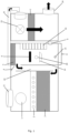
- FIG 1 shows an embodiment of a variant of a heating device according to the invention schematically from the front.
- the burner part is shown on the left and the heating part on the right.
- an opening or an inlet for primary air 9 is illustrated (shown here as a single opening, but there can also be several channels, but can also be designed in a grid shape or in another way; a grid shape has proven to be effective in order to prevent the fuel from escaping let).
- air flows into the combustion chamber 8.
- the combustion grate 19 the supply opening for the fuel 20 and, at the very bottom, the screw conveyor for the fuel waste removal 21 are indicated (the fuel collection chamber itself is not shown here, as it is behind it in this illustration the screw conveyor 21).
- the secondary air inlet 6 (shown here as a filled, rounded rectangle, in reality, for example, it can be designed in a grid shape or in another way; a grid shape has proven to be useful in order to prevent any firing material from escaping).
- the material to be burned is burned in the combustion chamber 8 and the flue gases rise. These abut the boundary of the combustion chamber 8 at the top, where they give off heat to a radiation heat exchanger 5 arranged thereon and otherwise follow the path to the left into the flue gas duct 22 (see filled arrow). The path through the flue gas duct 22 then leads downwards, in countercurrent along the (hot) wall to the combustion chamber 8.
- the path leads to the left (see filled arrow) and upwards into the area of the heat exchanger.
- the flue gas first flows through a flat tube flue gas heat exchanger 3 and then through a tertiary air heat exchanger 2.
- the suction fan 1 is arranged above it, through which a negative pressure is generated in the burner part.
- the flue gas flows outside through the chimney 11.
- the flue gas flap 4 which has a direct function if the temperature is too high Connection from the beginning of the flue gas duct 4 to the beginning of the chimney 11 is established in order to prevent overheating of the device or the heat transfer medium in the flat tube flue gas heat exchanger (illustrated here in the open position).
- the tertiary air heat exchanger 2 is shown here as a series of circles which represent tubes. Hot flue gas flows around these and tertiary air is sucked in from outside. This tertiary air then flows through lines (not shown) to the double-walled, internally hollow combustion chamber wall 10, which is illustrated here in the form of rectangles to indicate baffles that cause a meander-like flow guidance.
- the tertiary air flows upward in a meandering manner, being heated by the hot combustion chamber wall, and exits at the upper end through the opening of the double-walled, internally hollow combustion chamber wall 10 and enters the combustion chamber, preferably above the combustion zone and afterburning zone. The flue gas then flows through the burner part in the manner described.
- the heating part shown on the right in the figure includes an air intake fan 23, which sucks in air to be heated from the outside.
- the heating part also has a connection to the radiation heat exchanger 5 at its upper end with the air intake part 25 (whereby the air heated there is sucked in either from above the radiation heat exchanger 5 or through the radiation heat exchanger 5 - see filled arrow).
- part of the air sucked in is already heated (by the radiation heat exchanger 5) and part is sucked in directly from the environment.
- the air to be heated which is partly already slightly warmed, then flows down here and over the exhaust air heat exchanger 7 (see filled arrow), whereby the air is heated.
- the exhaust air heat exchanger 7 is flowed through by hot thermal oil, which was heated in the burner part in the flat tube flue gas heat exchanger 3 by the hot flue gas.
- the heated air then exits the device through the heated air outlet opening 24 (see solid arrow) and can be used for heating.
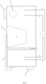
- FIG. 2 shows the design according to Figure 1 from behind, so the burner part is now on the right and the heating part on the left. Shown approximately in the middle of the figure is the (pellet) storage container 14, from which the fuel is fed into the combustion chamber is promoted. At the upper end of the (pellet) storage container 14, a radar probe 13 is illustrated, with which the fill level of the (pellet) storage container 14 is monitored.
- the suction pull fan 1 is shown as a circle on the right, since the corresponding drive motor of the fan is usually installed (as shown here) on the rear wall of the burner part. Below the suction fan 1 are the heat exchangers, which are not shown here.
- the flow to the flat tube flue gas heat exchanger 15 and the return from the flat tube flue gas heat exchanger 16, in connection with pump 12, are shown.
- the pump 12 is shown here below the housing, but this only serves to simplify the illustration; it is normally located directly on or a small piece of it behind the rear housing wall.
- the flow to the exhaust air heat exchanger 17 and the return from the exhaust air heat exchanger 18 are also connected to the pump, since the two heat exchangers form a circuit through which heat transfer medium, preferably thermal oil, flows. These two pipes end on the left in the heating part at the point where the exhaust air heat exchanger 7 is located.
- a heating device as shown in the figures, was charged with commercially available wood pellets as fuel and combustion was started. After reaching the stationary state, a temperature of between 220°C and 250°C was maintained on the flat tube flue gas heat exchanger.
- the air intake fan in the heating part ran with an output of approximately 6000 m 3 , resulting in an air volume flow of 10,000 m 3 , which could be heated to 82°C at an outside temperature of 0°C.
- the heating device according to the invention is very effective and achieves a high level of efficiency.
Description
Die vorliegende Erfindung betrifft eine Heizvorrichtung, bevorzugt für die Verbrennung von Biomasseprodukten, insbesondere von Pellets aus Biomasse, mit gesteigertem Wirkungsgrad, ein Verfahren zur Steigerung des Wirkungsgrads von (entsprechenden) Heizvorrichtungen sowie entsprechende Verwendungen.The present invention relates to a heating device, preferably for the combustion of biomass products, in particular biomass pellets, with increased efficiency, a method for increasing the efficiency of (corresponding) heating devices and corresponding uses.
Aus dem Stand der Technik sind verschiedenste Heizvorrichtungen bekannt. Auch ist es bekannt, Heizvorrichtungen mit Pellets zu betreiben. Die Heizvorrichtungen aus dem Stand der Technik weisen zum Beispiel neben dem Brennraum, in dem der Brennstoff verbrannt wird, auch angrenzend an den Brennraum oder die heisse Abgasleitung Wärmetauscher auf, die wiederum benutzt werden, um Wärme an die zu erwärmende Luft abzugeben, wobei Wasser oder Luft als Wärmeträger genutzt werden.A wide variety of heating devices are known from the prior art. It is also known to operate heating devices with pellets. The heating devices from the prior art, for example, in addition to the combustion chamber in which the fuel is burned, also have heat exchangers adjacent to the combustion chamber or the hot exhaust pipe, which in turn are used to give off heat to the air to be heated, with water or Air can be used as a heat carrier.
Als Stand der Technik können beispielsweise angeführt werden:
Bauartbedingt wird bei den Vorrichtungen des Standes der Technik über die Abgase recht viel Wärme ungenutzt in die Umgebung abgegeben. Der Wirkungsgrad dieser Vorrichtungen ist nicht optimal.Due to the design of the prior art devices, a lot of unused heat is released into the environment via the exhaust gases. The efficiency of these devices is not optimal.
Insofern existieren ausgehend von dem bisherigen Stand der Technik noch erhebliche Verbesserungspotentiale.In this respect, there is still considerable potential for improvement based on the current state of the art.
Aufgabe der vorliegenden Erfindung ist es demgemäss, Heizvorrichtungen zur Verfügung zu stellen, welche im Vergleich zu den Vorrichtungen des Standes der Technik verbesserte Wirkungsgrade aufzeigen.The object of the present invention is therefore to provide heating devices which have improved efficiencies compared to the devices of the prior art.
Gleichsam ist es Aufgabe der vorliegenden Erfindung ein Verfahren zur Verfügung zu stellen, mithilfe dessen eine Wirkungsgradsteigerung von Heizvorrichtungen erreicht werden kann.At the same time, it is the object of the present invention to provide a method by means of which an increase in the efficiency of heating devices can be achieved.
Schliesslich sollten Verwendungsmöglichkeiten für wirkungsgradgesteigerte Heizvorrichtungen gefunden werden.Finally, possible uses for heating devices with increased efficiency should be found.
Weitere Aufgabenstellungen ergeben sich aus der nachfolgenden Beschreibung.Further tasks result from the following description.
Gelöst werden diese und andere Aufgaben im Rahmen der vorliegenden Erfindung durch die Gegenstände der unabhängigen Ansprüche.These and other tasks are solved within the scope of the present invention by the subject matter of the independent claims.
Bevorzugte Ausgestaltungen ergeben sich aus den abhängigen Ansprüchen sowie der nachfolgenden Beschreibung.Preferred embodiments result from the dependent claims and the following description.
Im Rahmen der vorliegenden Erfindung sind Temperaturangaben, soweit nicht anders angegeben, in Grad Celsius (°C).In the context of the present invention, unless otherwise stated, temperatures are in degrees Celsius (°C).
Sofern nichts Anderes angegeben wird, wird die Verbrennung bei Umgebungsdruck (=Normaldruck/Atmosphärendruck), d.h. bei 1013 mbar, durchgeführt.Unless otherwise stated, combustion is carried out at ambient pressure (=normal pressure/atmospheric pressure), i.e. at 1013 mbar.
Im Rahmen der vorliegenden Erfindung schliesst der Begriff «umfassen» jeweils auch «bestehend aus» ein; das heisst eine entsprechende Liste kann neben den explizit genannten Elementen auch weitere Elemente enthalten (= umfassen), oder sie kann genau diese Elemente enthalten (=bestehen aus) (wobei unwesentliche Elemente wie Schrauben, Markierungen etc nicht berücksichtig sind).In the context of the present invention, the term “comprise” also includes “consisting of”; This means that a corresponding list can contain (= include) other elements in addition to the explicitly mentioned elements, or it can contain (= consist of) exactly these elements (whereby non-essential elements such as screws, markings, etc. are not taken into account).
Bei relativen Angaben wie oben, unten, links, rechts oder Ähnlichem wird im Rahmen der vorliegenden Erfindung als Bezugssystem von einem aufrecht auf dem Erdboden vor dem diskutierten Objekt stehenden Beobachter ausgegangen.For relative information such as above, below, left, right or similar, the reference system in the context of the present invention is an observer standing upright on the ground in front of the object under discussion.
Gegenstand der vorliegenden Erfindung ist insbesondere eine Heizvorrichtung umfassend:
- A) einen Brennerteil umfassend
- eine Brennkammer,
- eine doppelwandige, innen hohle Brennkammerwand, die eine obere Öffnung hat, die oberhalb der Brennzone in die Brennkammer mündet,
- einen Rauchgaskanal, der das Rauchgas entlang der Brennkammer nach unten führt,
- an den Rauchgaskanal anschliessend einen Wärmetauscherbereich umfassend
- zuerst einen Flachrohrrauchgaswärmetauscher,
- dann einen Tertiärluftwärmetauscher,
- einen Rauchgasabluftkamin,
- einen oberhalb der Brennkammer angeordneten Abstrahlungswärmetauscher,
- eine Rauchgasklappe am oberen Ende des Rauchgaskanals, die in geöffnetem Zustand den Rauchgaskanal mit dem Kamin verbindet,
- B) einen Heizteil umfassend
- ein Luftansauggebläse,
- einen Abluftwärmetauscher mit demselben Wärmeträger wie der Flachrohrrauchgaswärmetauscher,
- einer Auslassöffnung für die erwärmte Luft,
- A) comprising a burner part
- a combustion chamber,
- a double-walled, internally hollow combustion chamber wall which has an upper opening which opens into the combustion chamber above the combustion zone,
- a flue gas duct that leads the flue gas down along the combustion chamber,
- comprising a heat exchanger area adjoining the flue gas duct
- first a flat tube flue gas heat exchanger,
- then a tertiary air heat exchanger,
- a smoke exhaust chimney,
- a radiation heat exchanger arranged above the combustion chamber,
- a flue gas flap at the upper end of the flue gas duct, which, when open, connects the flue gas duct with the chimney,
- B) comprising a heating part
- an air intake fan,
- an exhaust air heat exchanger with the same heat transfer medium as the flat tube flue gas heat exchanger,
- an outlet opening for the heated air,
In bevorzugten Ausführungsformen der vorliegenden Erfindung umfasst die Brennkammer Einlasskanäle oder Einlassöffnungen für Primärluft und Sekundärluft, ein Brennrost und einen Brenner, eine Zuführöffnung für Brennstoff und eine Brennstoffabfallsammelkammer und/oder eine Brennstoffabfallabführvorrichtung, bevorzugt einen Kanal, insbesondere durch eine Förderschnecke zum Abtransport des Brennstoffabfalls mit der Brennkammer verbunden. Weiterhin kann in Varianten vorgesehen sein, ein Kontrollfenster vorzusehen, mit dem die Verbrennung in der Brennkammer visuell überprüft werden kann. Es ist aber auch möglich und in Varianten der Erfindung bevorzugt, die Verbrennung mittels elektronischer Überwachung, beispielsweise Thermosensoren und Kameras (automatisch) zu überwachen.In preferred embodiments of the present invention, the combustion chamber comprises inlet channels or inlet openings for primary air and secondary air, a combustion grate and a burner, a supply opening for fuel and a fuel waste collection chamber and/or a fuel waste removal device, preferably a channel, in particular through a screw conveyor for transporting the fuel waste with the Combustion chamber connected. Furthermore, in variants it can be provided to provide a control window with which the combustion in the combustion chamber can be visually checked. However, it is also possible and preferred in variants of the invention to monitor the combustion (automatically) using electronic monitoring, for example thermal sensors and cameras.
In einigen bevorzugten Varianten der vorliegenden Erfindung ist der Primärlufteinlass in die Brennkammer das Ende eines Luftansaugkanals, der an der Brennkammerwand entlanggeführt wird. Dies bewirkt, dass im laufenden Betrieb die Primärluft bereits vorgewärmt (durch Wärme, die über die Brennkammerwand abgestrahlt wird) in das System eintritt; zusätzlich wird durch die Brennkammerwand abgestrahlte Hitze sinnvoll genutzt und nicht ungenutzt abgegeben. Gleichsam kann auch die Sekundärluft durch einen entsprechenden Kanal vorgewärmt werden.In some preferred variants of the present invention, the primary air inlet into the combustion chamber is the end of an air intake duct which is routed along the combustion chamber wall. This causes the primary air to enter the system already preheated (by heat radiated through the combustion chamber wall) during operation; In addition, heat radiated through the combustion chamber wall is used sensibly and is not given away unused. At the same time, the secondary air can also be preheated through a corresponding channel.
Die Zündung der Verbrennung kann auf beliebige fachüblich Art und Weise erfolgen, zum Beispiel kann eine Gasflamme zur Entzündung verwendet werden. Diese kann in Form eines kleinen Gasbrenners Teil der Vorrichtung sein. Oder es kann ein keramisches Zündelement, als Teil der Vorrichtung, mittels Luftstrom zur Entzündung genutzt werden.The combustion can be ignited in any conventional manner, for example a gas flame can be used for ignition. This can be part of the device in the form of a small gas burner. Or a ceramic ignition element, as part of the device, can be used for ignition using an air flow.
In bevorzugten Ausführungsformen der vorliegenden Erfindung umfasst die Heizvorrichtung einen (Pellet-)Vorratsbehälter, der mit der Brennkammer über die Zuführöffnung für Brennstoff verbunden ist, bevorzugt über eine Förderschnecke, umfasst.In preferred embodiments of the present invention, the heating device comprises a (pellet) storage container which is connected to the combustion chamber via the supply opening for fuel, preferably via a screw conveyor.
In bevorzugten Ausführungsformen der vorliegenden Erfindung mündet die obere Öffnung der doppelwandigen, innen hohlen Brennkammerwand oberhalb von Brennzone und Nachbrennzone in die Brennkammer. Zusätzlich kann die doppelwandige, innen hohle Brennkammerwand in bevorzugten Varianten der vorliegenden Erfindung eine untere Öffnung oder einen Anschluss, konfiguriert Tertiärluft eingeleitet zu bekommen, aufweisen. Dadurch wird erreicht, dass die schon durch den Tertiärluftwärmetauscher vorgewärmte Luft durch die Wand (der Brennkammer) hindurch in der doppelwandigen, innen hohlen Brennkammerwand weiter erwärmt wird und in quasi doppelt vorgewärmten Zustand oberhalb der Brennzone in die Brennkammer eingeleitet und mit dem Rauchgas vermischt wird. Daraus ergeben sich mehrere vorteilhafte Effekte: zum Einen wird das Rauchgas verdünnt, so dass die später aus dem Kamin austretenden Abgase eine geringere Schadstoffkonzentration aufweisen. Zum Anderen wird erreicht, dass mittels der Tertiärluft Energie «abgefangen» wird, die sonst ungenutzt, zum Einen direkt nach dem Wärmetauscherbereich und zum Anderen durch die Brennkammerwand hindurch, aus dem System entweichen würde.In preferred embodiments of the present invention, the upper opening of the double-walled, internally hollow combustion chamber wall opens into the combustion chamber above the combustion zone and afterburning zone. Additionally, in preferred variants of the present invention, the double-walled, internally hollow combustion chamber wall may have a lower opening or port configured to introduce tertiary air. This ensures that the air that has already been preheated by the tertiary air heat exchanger is further heated through the wall (of the combustion chamber) in the double-walled, internally hollow combustion chamber wall and is introduced into the combustion chamber above the combustion zone in a quasi doubly preheated state and mixed with the flue gas. This results in several advantageous effects: on the one hand, the flue gas is diluted so that the exhaust gases that later emerge from the chimney have a lower concentration of pollutants. On the other hand, the tertiary air is used to “capture” energy that would otherwise escape unused from the system, on the one hand directly after the heat exchanger area and on the other hand through the combustion chamber wall.
In bevorzugten Ausführungsformen der vorliegenden Erfindung ist der Rauchgaskanal im Bezug zu der doppelwandigen, innen hohlen Brennkammerwand auf der anderen Seite der Brennkammer angeordnet, und das Rauchgas wird entlang der an der Brennkammer befindlichen Wand des Rauchgaskanals nach unten führt. Es wird also eine Art Gegenstrom-Prinzip angewendet, wodurch die Rauchgase durch die aufgeheizte Wand (der Brennkammer) weiter erwärmt werden. Dies bewirkt zusammen mit der Tertiärluft-Nutzung auch, dass die durch die Brennkammerwand strahlende Wärmeenergie genutzt wird und nicht ungenutzt das System verlässt.In preferred embodiments of the present invention, the flue gas duct is arranged on the other side of the combustion chamber in relation to the double-walled, internally hollow combustion chamber wall, and the flue gas is led downwards along the wall of the flue gas duct located on the combustion chamber. A kind of countercurrent principle is used, whereby the flue gases flow through the heated wall (of the combustion chamber) can be heated further. Together with the use of tertiary air, this also means that the thermal energy radiating through the combustion chamber wall is used and does not leave the system unused.
In weiteren bevorzugten Ausführungsformen der vorliegenden Erfindung können die Brennkammerseitenwände, abgesehen von den Einlässen für Primär- und Sekundärluft sowie Brennstoffzufuhr und gegebenenfalls die Brennstoffabfuhr, vollständig von Rauchgaskanal und doppelwandiger, innen hohler Brennkammerwand umschlossen sein, beispielsweise etwa je zur Hälfte, oder im Verhältnis 1:2, oder 1:3, oder 1:4 oder beliebigen anderen Verhältnissen von Rauchgaskanal zu doppelwandiger, innen hohler Brennkammerwand, jeweils bezogen auf den Anteil am Umfang der jeweils abgedeckten Brennkammerwand. Dies kann das «Abfangen» von durch die Brennkammerseitenwände abgestrahlter Energie optimieren. Selbstverständlich ist es auch möglich, in diesem Falle weitere Aussparungen für zum Beispiel Sicht- und/oder Kontrollfenster vorzusehen.In further preferred embodiments of the present invention, the combustion chamber side walls, apart from the inlets for primary and secondary air as well as fuel supply and possibly fuel removal, can be completely enclosed by the flue gas duct and the double-walled, internally hollow combustion chamber wall, for example approximately half each, or in a ratio of 1: 2, or 1:3, or 1:4 or any other ratio of flue gas duct to double-walled, hollow combustion chamber wall, in each case based on the proportion of the circumference of the combustion chamber wall covered. This can optimize the “interception” of energy radiated through the combustion chamber side walls. Of course, it is also possible in this case to provide further recesses for, for example, viewing and/or control windows.
In bevorzugten Ausführungsformen der vorliegenden Erfindung ist der Wärmetauscherbereich in Strömungsrichtung des Rauchgases jenseits des Rauchgaskanals angeordnet. Dabei wird der Flachrohrrauchgaswärmetauscher mit Thermalöl als Wärmeträger betrieben. Das Thermalöl wird bevorzugt ausgewählt aus Mineralölen, Synthetikölen oder Silikonölen, besonders bevorzugt wird im Rahmen der vorliegenden Erfindung Silikonöl eingesetzt. Der Tertiärluftwärmetauscher weist dabei Einlasskanäle oder Einlassöffnungen für Tertiärluft und Ableitungen, die mit der doppelwandigen, innen hohlen Brennkammerwand verbunden sind, für die erwärmte Tertiärluft auf. Der Tertiärluftwärmetauscher zieht dabei Luft von aussen an, die dann durch das Rauchgas erwärmt wird. Die so erwärmte Luft wird dann zu der doppelwandigen, innen hohlen Brennkammerwand geleitet, durch diese unter weiterer Erwärmung hindurch und schliesslich oberhalb der Brennzone in die Brennkammer. Die doppelwandige Brennkammerwand ist bevorzugt mit innenliegenden Prallblechen, die jeweils einen Teil des Strömungsweges blockieren und den Luftstrom mithin umlenken, ausgestaltet, so dass sich ein Luftstrom ergibt, der das Innere der doppelwandige Brennkammerwand mäanderartig bzw. geschlängelt durchströmt. Dies bewirkt, dass der Tertiärluftstrom quasi vollständig an der (heissen) Brennkammerwand entlangströmt und mithin eine möglichst effektive Wärmeübertragung auf die Tertiärluft erfolgt.In preferred embodiments of the present invention, the heat exchanger region is arranged beyond the flue gas duct in the flow direction of the flue gas. The flat tube flue gas heat exchanger is operated with thermal oil as a heat transfer medium. The thermal oil is preferably selected from mineral oils, synthetic oils or silicone oils; silicone oil is particularly preferably used in the context of the present invention. The tertiary air heat exchanger has inlet channels or inlet openings for tertiary air and drains, which are connected to the double-walled, internally hollow combustion chamber wall, for the heated tertiary air. The tertiary air heat exchanger draws in air from outside, which is then heated by the flue gas. The air heated in this way is then directed to the double-walled, internally hollow combustion chamber wall, through it with further heating and finally into the combustion chamber above the combustion zone. The double-walled combustion chamber wall is preferably designed with internal baffle plates, which each block part of the flow path and therefore redirect the air flow, so that an air flow results that flows through the interior of the double-walled combustion chamber wall in a meandering or meandering manner. This means that the tertiary air flow is almost completely at the (hot) Flows along the combustion chamber wall and therefore the most effective heat transfer to the tertiary air takes place.
In bevorzugten Ausführungsformen der vorliegenden Erfindung schliesst anschliessend an den Wärmetauscherbereich ein Bereich mit Saug-Zuggebläse an; in Varianten kann ein Saug-Zuggebläse aber auch im oder am Rauchgasabluftkamin angeordnet sein, gegebenenfalls auch zusätzlich. Diese Gebläse haben den Sinn in dem Brennerteil einen Unterdruck zu erzeugen, so dass einerseits Luft (Primär-, Sekundär- und Tertiärluft) durch die Vorrichtung gesaugt wird, und andererseits keine Rauchgase durch eventuelle Undichtigkeiten austreten.In preferred embodiments of the present invention, the heat exchanger area is followed by an area with a suction fan; In variants, a suction fan can also be arranged in or on the flue gas exhaust chimney, if necessary additionally. The purpose of these blowers is to create a negative pressure in the burner part, so that on the one hand air (primary, secondary and tertiary air) is sucked through the device and on the other hand no smoke gases escape through possible leaks.
In bevorzugten Ausführungsformen der vorliegenden Erfindung umfasst das Heizteil ein Luftansaugteil, bevorzugt in Form von mindestens einem Luftkanal, das Luft von oberhalb des Abstrahlungswärmetauschers oder durch den Abstrahlungswärmetauscher ansaugt.In preferred embodiments of the present invention, the heating part comprises an air intake part, preferably in the form of at least one air duct, which draws air from above the radiation heat exchanger or through the radiation heat exchanger.
In bevorzugten Ausführungsformen der vorliegenden Erfindung ist das Luftansauggebläse des Heizteils so konfiguriert bzw. so umbaut, dass es zumindest zum Teil, bevorzugt zum Teil, besonders bevorzugt 40 bis 60%, insbesondere 50%, Luft aus dem Luftansaugteil ansaugt und ansonsten Luft aus der Umgebung ansaugt, wobei sich die Prozente auf die Gesamt-Volumenmenge angesaugter Luft beziehen.In preferred embodiments of the present invention, the air intake fan of the heating part is configured or modified in such a way that it sucks in at least some, preferably some, particularly preferably 40 to 60%, in particular 50%, air from the air intake part and otherwise air from the environment sucks in, whereby the percentages refer to the total volume of air sucked in.
In bevorzugten Ausführungsformen der vorliegenden Erfindung sind die beiden Teile A) und B) (Brennerteil und Heizteil) durch die Verrohrung des Flachrohrrauchgaswärmetauschers mit dem Abluftwärmetauscher, und gegebenenfalls durch die Verbindung der Luftansaugung des Heizteils zu dem Abstrahlungswärmetauscher, verbunden und ansonsten physikalisch getrennte Einheiten. Allerdings ist es im Rahmen der vorliegenden Erfindung ebenfalls möglich, und demgemäss in Varianten bevorzugt, die beiden Teil fest miteinander zu verbinden (durch Verschrauben, Verschweissen, Vernieten etc.).In preferred embodiments of the present invention, the two parts A) and B) (burner part and heating part) are connected by the piping of the flat tube flue gas heat exchanger to the exhaust air heat exchanger, and optionally by connecting the air intake of the heating part to the radiation heat exchanger, and are otherwise physically separate units. However, within the scope of the present invention, it is also possible and therefore preferred in variants to firmly connect the two parts to one another (by screwing, welding, riveting, etc.).
Eine besonders bevorzugte Heizvorrichtung gemäss vorliegender Erfindung, bevorzugt für die Verbrennung von Biomasse, insbesondere von Pellets aus Biomasse, umfasst oder besteht demnach aus:
- A) einem Brennerteil umfassend
- eine Brennkammer umfassend
- Einlasskanäle oder Einlassöffnungen für Primärluft und Sekundärluft,
- ein Brennrost und einen Brenner
- eine Zuführöffnung für Brennstoff,
- eine Brennstoffabfallsammelkammer und/oder eine Brennstoffabfallabführvorrichtung, bevorzugt einen Kanal, insbesondere durch eine Förderschnecke zum Abtransport des Brennstoffabfalls mit der Brennkammer verbunden,
- einen (Pellet-)Vorratsbehälter, der mit der Brennkammer über die Zuführöffnung für Brennstoff verbunden ist, bevorzugt über eine Förderschnecke,
- eine doppelwandige, innen hohle Brennkammerwand, die eine obere Öffnung hat, die oberhalb der Brennzone, bevorzugt oberhalb von Brennzone und Nachbrennzone, in die Brennkammer mündet, und eine untere Öffnung oder Anschluss, konfiguriert Tertiärluft eingeleitet zu bekommen, aufweist,
- einen Rauchgaskanal, der im Bezug zu der doppelwandigen, innen hohlen Brennkammerwand auf der anderen Seite der Brennkammer angeordnet ist, und das Rauchgas von oben herab entlang seiner an die Brennkammer grenzenden Wand nach unten führt,
- an den Rauchgaskanal anschliessend, aus Blickrichtung der Brennkammer jenseits des Rauchgaskanals angeordnet, einen Wärmetauscherbereich umfassend
- zuerst einen Flachrohrrauchgaswärmetauscher, bevorzugt mit Thermalöl als Wärmeträger,
- dann einen Tertiärluftwärmetauscher umfassend Einlasskanäle oder Einlassöffnungen für Tertiärluft und Ableitungen für die erwärmte Tertiärluft, die mit der doppelwandigen, innen hohlen Brennkammerwand verbunden sind,
- optional anschliessend an den Wärmetauscherbereich einen Bereich mit Saug-Zuggebläse,
- einen Rauchgasabluftkamin,
- einen oberhalb der Brennkammer angeordneten Abstrahlungswärmetauscher,
- eine Rauchgasklappe am oberen Ende des Rauchgaskanals, die in geöffnetem Zustand den Rauchgaskanal mit dem Kamin verbindet,
- eine Brennkammer umfassend
- B) einem Heizteil umfassend
- ein Luftansaugteil, das Luft von oberhalb des Abstrahlungswärmetauscher oder durch den Abstrahlungswärmetauscher ansaugt,
- ein Luftansauggebläse, das zumindest zum Teil, bevorzugt zum Teil, besonders bevorzugt 40 bis 60%, insbesondere 50%, Luft aus dem Luftansaugteil ansaugt und ansonsten Luft aus der Umgebung ansaugt, wobei sich die Prozente auf die Gesamtmenge angesaugter Luft beziehen,
- einen Abluftwärmetauscher mit demselben Wärmeträger wie der Flachrohrrauchgaswärmetauscher, bevorzugt Thermalöl,
- einer Auslassöffnung für die erwärmte Luft,
- A) comprising a burner part
- comprising a combustion chamber
- Inlet channels or inlet openings for primary air and secondary air,
- a burning grate and a burner
- a supply opening for fuel,
- a fuel waste collection chamber and/or a fuel waste removal device, preferably a channel, in particular connected to the combustion chamber by a screw conveyor for removing the fuel waste,
- a (pellet) storage container which is connected to the combustion chamber via the feed opening for fuel, preferably via a screw conveyor,
- a double-walled, internally hollow combustion chamber wall, which has an upper opening which opens into the combustion chamber above the combustion zone, preferably above the combustion zone and afterburning zone, and a lower opening or connection, configured to have tertiary air introduced,
- a flue gas duct which is arranged on the other side of the combustion chamber in relation to the double-walled, internally hollow combustion chamber wall, and which leads the flue gas downwards from above along its wall bordering the combustion chamber,
- adjoining the flue gas duct, arranged beyond the flue gas duct when viewed from the direction of the combustion chamber, comprising a heat exchanger area
- first a flat tube flue gas heat exchanger, preferably with thermal oil as a heat transfer medium,
- then a tertiary air heat exchanger comprising inlet channels or inlet openings for tertiary air and discharge lines for the heated tertiary air, which are connected to the double-walled, internally hollow combustion chamber wall,
- optionally an area with a suction fan following the heat exchanger area,
- a smoke exhaust chimney,
- a radiation heat exchanger arranged above the combustion chamber,
- a flue gas flap at the upper end of the flue gas duct, which, when open, connects the flue gas duct with the chimney,
- comprising a combustion chamber
- B) comprising a heating part
- an air intake part that draws air from above the radiant heat exchanger or through the radiant heat exchanger,
- an air intake fan which at least partially, preferably partially, particularly preferably 40 to 60%, in particular 50%, sucks in air from the air intake part and otherwise sucks in air from the environment, the percentages referring to the total amount of air sucked in,
- an exhaust air heat exchanger with the same heat transfer medium as the flat tube flue gas heat exchanger, preferably thermal oil,
- an outlet opening for the heated air,
Die Tatsache, dass Heizteil und Brennerteil eigenständige Einheiten sind, ermöglicht eine flexible Handhabung. So kann bei Defekt eines Teils schnell dieses Teil ausgetauscht werden, ohne dass die ganze Heizvorrichtung getauscht werden müsste. Weiterhin ist es damit möglich, einzelne Teile zu tauschen, um dies an die Gegebenheiten anzupassen, also zum Beispiel grössere oder kleinere Einheiten aufzustellen. Gleichwohl werden Heizteil und Brennerteil gewöhnlich gemeinsam als eine Heizvorrichtung genutzt/transportiert/aufgestellt werden, insbesondere dann, wenn diese als mobile Variante ausgestaltet ist (wofür dann ein Rahmen oder Stützrahmen, was ein PKW-Anhängerrahmen sein kann, vorgesehen sein kann).The fact that the heating part and burner part are independent units enables flexible handling. This means that if a part is defective, this part can be quickly replaced without having to replace the entire heating device. Furthermore, it is possible to exchange individual parts in order to adapt this to the circumstances, for example to set up larger or smaller units. Nevertheless, the heating part and the burner part are usually used/transported/set up together as a heating device, especially if this is designed as a mobile variant (for which a frame or support frame, which can be a car trailer frame, can then be provided).
Im Rahmen der vorliegenden Erfindung kann die Auslassöffnung für erwärmte Luft in entsprechenden Weiterbildungen mit einem Schlauch versehen werden, um die austretende erwärmte Luft besser an den gewollten Zielort dirigieren/leiten zu können.Within the scope of the present invention, the outlet opening for heated air can be provided with a hose in corresponding developments in order to be able to better direct/guide the exiting heated air to the desired destination.
Gegenstand der vorliegenden Erfindung ist ferner ein Verfahren zur Steigerung des Wirkungsgrads einer Heizvorrichtung durch
- befeuern einer Verbrennung in einer Brennkammer, wie im Rahmen dieser Erfindung beschrieben, unter Zuführung von Primärluft durch die Brennzone und Zufuhr von Sekundärluft am oberen Ende der Brennzone,
- leiten des Rauchgases über zunächst einen Flachrohrrauchgaswärmetauscher und dann über einen Tertiärluftwärmetauscher,
- leiten der so erwärmten Tertiärluft in eine doppelwandige, innen hohle Brennkammerwand zur weiteren Erwärmung,
- einleiten der erwärmten Tertiärluft aus der doppelwandigen, innen hohlen Brennkammerwand in die Brennkammer oberhalb der Brennzone, bevorzugt oberhalb von Brennzone und Nachbrennzone, und Vermischung mit dem Rauchgas,
- übertragen von Wärme auf zumindest einen Teil der zu erwärmenden Luft, durch einen oberhalb der Brennkammer angeordneten Wärmetauscher,
- übertragen von weiterer Wärme auf die zu erwärmende Luft durch einen Abluftwärmetauscher mittels im Flachrohrrauchgaswärmetauscher und/oder Lamellenwärmetauscher erwärmten Wärmeträger, bevorzugt Thermalöl, insbesondere Silikonöl.
- firing a combustion in a combustion chamber, as described in the context of this invention, with supply of primary air through the combustion zone and supply of secondary air at the upper end of the combustion zone,
- passing the flue gas first through a flat tube flue gas heat exchanger and then through a tertiary air heat exchanger,
- directing the heated tertiary air into a double-walled, internally hollow combustion chamber wall for further heating,
- introducing the heated tertiary air from the double-walled, internally hollow combustion chamber wall into the combustion chamber above the combustion zone, preferably above the combustion zone and afterburning zone, and mixing it with the flue gas,
- transferring heat to at least part of the air to be heated through a heat exchanger arranged above the combustion chamber,
- transferring further heat to the air to be heated through an exhaust air heat exchanger by means of heat transfer medium heated in the flat tube flue gas heat exchanger and/or finned heat exchanger, preferably thermal oil, in particular silicone oil.
Ein weiterer Gegenstand der vorliegenden Erfindung ist ein Brennerteil für Heizvorrichtungen, wie im Übrigen in dieser Anmeldung beschrieben. Die Verrohrung des zur Wärmeübertragung an ein Heizteil gedachten Wärmetauschers ist dabei nur optional; sie kann vorinstalliert sein, muss es aber nicht. Wesentlich für diesen Gegenstand der vorliegenden Erfindung ist die Luft und Gasführung in Zusammenhang mit den installierten Wärmetauschern des Brennerteils.Another subject of the present invention is a burner part for heating devices, as otherwise described in this application. The piping of the heat exchanger intended for heat transfer to a heating part is only optional; it may or may not be pre-installed. Essential for this subject of the present invention is the air and gas flow in connection with the installed heat exchangers of the burner part.
Bevorzugt ist demgemäss ein Brennerteil, bevorzugt für eine Heizvorrichtung, umfassend
- eine Brennkammer umfassend Einlasskanäle oder Einlassöffnungen für Primärluft und Sekundärluft, ein Brennrost und einen Brenner, eine Zuführöffnung für Brennstoff, eine Brennstoffabfallsammelkammer und/oder eine Brennstoffabfallabführvorrichtung,
- einen (Pellet-)Vorratsbehälter, der mit der Brennkammer über die Zuführöffnung für Brennstoff verbunden ist, bevorzugt über eine Förderschnecke,
- eine doppelwandige, innen hohle Brennkammerwand, die eine obere Öffnung hat, die oberhalb der Brennzone, bevorzugt oberhalb von Brennzone und Nachbrennzone, in die Brennkammer mündet, und eine untere Öffnung, konfiguriert Tertiärluft eingeleitet zu bekommen,
- einen Rauchgaskanal, der im Bezug zu der doppelwandigen, innen hohlen Brennkammerwand auf der anderen Seite der Brennkammer angeordnet ist, und das Rauchgas von oben herab entlang seiner an die Brennkammer grenzenden Wand nach unten führt,
- an den Rauchgaskanal anschliessend, in Strömungsrichtung des Rauchgases jenseits des Rauchgaskanals angeordnet, einen Wärmetauscherbereich umfassend zuerst einen Flachrohrrauchgaswärmetauscher, bevorzugt mit Thermalöl als Wärmeträger, dann einen Tertiärluftwärmetauscher umfassend Einlasskanäle oder Einlassöffnungen für Tertiärluft und Ableitungen für die erwärmte Tertiärluft, die mit der doppelwandigen, innen hohlen Brennkammerwand verbunden sind,
- optional anschliessend an den Wärmetauscherbereich einen Bereich mit Saug-Zuggebläse,
- einen Rauchgasabluftkamin,
- einen oberhalb der Brennkammer angeordneten Abstrahlungswärmetauscher,
- eine Rauchgasklappe am oberen Ende des Rauchgaskanals, die in geöffnetem Zustand den Rauchgaskanal mit dem Kamin verbindet.
- a combustion chamber comprising inlet channels or inlet openings for primary air and secondary air, a combustion grate and a burner, a fuel supply opening, a fuel waste collection chamber and/or a fuel waste discharge device,
- a (pellet) storage container which is connected to the combustion chamber via the feed opening for fuel, preferably via a screw conveyor,
- a double-walled, internally hollow combustion chamber wall which has an upper opening which opens into the combustion chamber above the combustion zone, preferably above the combustion zone and afterburning zone, and a lower opening, configured to introduce tertiary air,
- a flue gas duct which is arranged on the other side of the combustion chamber in relation to the double-walled, internally hollow combustion chamber wall, and which leads the flue gas downwards from above along its wall bordering the combustion chamber,
- adjoining the flue gas duct, arranged in the flow direction of the flue gas beyond the flue gas duct, a heat exchanger area comprising first a flat tube flue gas heat exchanger, preferably with thermal oil as a heat transfer medium, then a tertiary air heat exchanger comprising inlet channels or inlet openings for tertiary air and discharge lines for the heated tertiary air, which are connected to the double-walled, hollow inside combustion chamber wall are connected,
- optionally an area with a suction fan following the heat exchanger area,
- a smoke exhaust chimney,
- a radiation heat exchanger arranged above the combustion chamber,
- a flue gas flap at the upper end of the flue gas duct, which, when open, connects the flue gas duct with the chimney.
Weiterer Gegenstand der vorliegenden Erfindung ist die Verwendung der erfindungsgemässen Heizvorrichtung zur Erwärmung von zu erwärmenden Bereichen, insbesondere (teilweise) abgetrennten Bereichen, insbesondere Räumen. Zu den Räumen zählen im Rahmen der vorliegenden Erfindung neben Zimmern auch Zelte, Jahrmarktbuden oder ähnliches.A further subject of the present invention is the use of the heating device according to the invention for heating areas to be heated, in particular (partially) separated areas, in particular rooms. In the context of the present invention, the rooms include not only rooms but also tents, fair stalls or the like.
Zudem ist noch Gegenstand der vorliegenden Erfindung die Verwendung des erfindungsgemässen Verfahrens zur Erhöhung der Effizienz von Heizvorrichtungen. Ausserdem ist Gegenstand der vorliegenden Erfindung die Verwendung des erfindungsgemäss Brennerteils zur Verbrennung von Brennstoffen, bevorzugt aus Biomasse, insbesondere Holzpellets, oder zur Erwärmung von zu erwärmenden Bereichen, optional zusammen mit einem Heizteil, insbesondere einem Heizteil wie im Übrigen in dieser Anmeldung beschreiben.In addition, the present invention also relates to the use of the method according to the invention to increase the efficiency of heating devices. In addition, the subject of the present invention is the use of the burner part according to the invention for burning fuels, preferably from biomass, in particular wood pellets, or for heating areas to be heated, optionally together with a heating part, in particular a heating part as otherwise described in this application.
Weitere bevorzugte Ausgestaltungen finden sich im Folgenden.Further preferred embodiments can be found below.
Die Heizvorrichtung der vorliegenden Erfindung kann sowohl als stationäre Einheit ausgestaltet sein, als auch als mobile Einheit. In einigen bevorzugten Varianten ist sie als mobile Einheit ausgestaltet. In diesem Fall können unter die Heizvorrichtung Rollen oder Rädern montiert sein. In weiteren Varianten kann die Heizvorrichtung auf einem handelsüblichen PKW-Anhänger montiert oder angeordnet sein. In weiteren Varianten kann sie als Vorrichtung auf Rädern mit Anhängerkupplung ausgestaltet sein, also selbst einen Anhänger darstellen.The heating device of the present invention can be designed both as a stationary unit and as a mobile unit. In some preferred variants it is designed as a mobile unit. In this case, rollers or wheels can be mounted under the heating device. In further variants, the heating device can be mounted or arranged on a commercially available car trailer. In further variants, it can be designed as a device on wheels with a trailer hitch, i.e. it can itself represent a trailer.
Die Heizvorrichtung der vorliegenden Erfindung ist nicht auf eine bestimmte Grösse festgelegt. Für einen möglichst flexiblen und ökonomischen Einsatz sind jedoch Grössen vorteilhaft, die handelsüblichen PKW-Anhängern entsprechen bzw. auf diese passen. Insofern sind die Vorrichtungen der vorliegenden Erfindung in bevorzugten Ausführungsformen ca. 1 bis 3 m lang, 1,5 bis 2,5 m breit und 1,5 bis 2,5 m hoch. Sofern die erfindungsgemässen Heizvorrichtungen (bzw. das erfindungsgemässe Brennerteil) Räder oder Rollen aufweisen oder auf einen PKW-Anhänger verladbar sind, kann die Vorrichtung als mobile Heizvorrichtung bezeichnet werden.The heater of the present invention is not limited to a specific size. However, for the most flexible and economical use possible, sizes that correspond to or fit onto standard car trailers are advantageous. In this respect, the devices of the present invention are in preferred embodiments approximately 1 to 3 m long, 1.5 to 2.5 m wide and 1.5 to 2.5 m high. If the heating devices according to the invention (or the burner part according to the invention) have wheels or rollers or can be loaded onto a car trailer, the device can be referred to as a mobile heating device.
In Varianten bevorzugt ist es, wenn die erfindungsgemässe Heizvorrichtung (oder das erfindungsgemässe Brennerteil) elektronisch geregelt und/oder gesteuert wird. Dazu sind entsprechende Sensoren und mindestens eine Steuereinheit an der Vorrichtung angeordnet. Entsprechend weist die Steuereinheit eine Bedieneinheit auf, mit der diese von einem Nutzer bedient werden kann.In variants, it is preferred if the heating device according to the invention (or the burner part according to the invention) is regulated and/or controlled electronically. For this purpose, corresponding sensors and at least one control unit are arranged on the device. Accordingly, the control unit has an operating unit with which it can be operated by a user.
Wahlweise ist es auch möglich, eine Steuereinheit an der Vorrichtung anzuordnen, die aus der Ferne bedient werden und mithin aus der Ferne die Vorrichtung gesteuert werden kann (wenn es zum Beispiel zu warm in dem beheizten Bereich wird, kann die Leistung der Vorrichtung heruntergeregelt werden). Eine solche Steuerung aus der Ferne kann über W-LAN, Bluetooth (oder anderen Funk) oder ähnliches erfolgen, zum Beispiel auch mittels einer (Smartphone-) App.Alternatively, it is also possible to arrange a control unit on the device, which is operated remotely and therefore controls the device remotely (for example, if it becomes too warm in the heated area, the performance of the device can be reduced). Such remote control can take place via Wi-Fi, Bluetooth (or other radio) or similar, for example using a (smartphone) app.
Die erfindungsgemässe Steuerung wird bevorzugt so betrieben, dass beim Aufheizen bzw. Anfahren des Brennvorgangs und beim laufenden Betrieb optimale Luftzufuhr und Rauchgasabfuhr gewährleistet ist, insbesondere durch regeln der Stärke des Saug-Zuggebläses im Brennerteil sowie gegebenenfalls öffnen und schliessen von Drosselklappen in den Primär-, Sekundär- und Tertiärluftkanälen bzw. -einlässen. Zusätzlich wird das Luftansauggebläse des Heizteils in Varianten so geregelt, dass ein optimales Luftstrom/Wärmeaufnahme-Verhältnis erzielt wird. Es ist bevorzugt, beim Aufheizen bzw. Anfahren noch keine Tertiärluft zuzuführen. Diese würde zum Beispiel zunächst den Rauchgasstrom kühlen und entsprechend würde der Kamineffekt verringert (so dass mehr Leistung für das Gebläse nötig wäre).The control according to the invention is preferably operated in such a way that optimal air supply and smoke gas removal is guaranteed when heating up or starting the combustion process and during ongoing operation, in particular by regulating the strength of the suction fan in the burner part and, if necessary, opening and closing throttle valves in the primary, Secondary and tertiary air ducts or inlets. In addition, the air intake fan of the heating part is regulated in variants so that an optimal air flow/heat absorption ratio is achieved. It is preferred not to supply any tertiary air when heating up or starting up. For example, this would initially cool the flue gas flow and the chimney effect would be reduced accordingly (so that more power would be required for the fan).
Im Verlauf des Brennvorgangs (also nach dem Aufheizen/Anfahren) reicht die Sogwirkung der in der doppelwandigen, innen hohlen Brennkammerwand aufsteigenden Luft (aufgrund dessen, dass sie erwärmt wird), um die benötigte Menge Tertiärluft in das System zu bringen. Es ist aber im Rahmen der Erfindung ebenfalls möglich, hilfsweise ein Gebläse im Tertiärluftsystem zu arrangieren. Ähnlich reichen meist auch für Primär- bzw. Sekundärluft die Öffnungen/Einlässe zur Luftversorgung; allerdings kann auch hierbei jeweils ein Gebläse angeordnet werden, um den jeweiligen Luftstrom zu unterstützen (beispielsweise um die Verbrennung «anzufachen»).During the course of the combustion process (i.e. after heating up/starting up), the suction effect of the air rising in the double-walled, internally hollow combustion chamber wall (due to the fact that it is heated) is sufficient to bring the required amount of tertiary air into the system. However, within the scope of the invention, it is also possible to alternatively arrange a blower in the tertiary air system. Similarly, the openings/inlets for air supply are usually sufficient for primary or secondary air; However, a fan can also be arranged here to support the respective air flow (for example to “spark” the combustion).
Ferner wird bevorzugt die Position der Rauchgasklappe in Abhängigkeit von der Temperatur im Brennerteil geregelt. Es ist zwar möglich, dies über mechanische Vorrichtungen, wie Schmelzsicherungen oder ähnliches umzusetzen, jedoch ist dies in dem Sinne weniger bevorzugt, als dass solche Sicherungen nach Einsatz getauscht werden müssen. Insofern wird die Rauchgasklappe bevorzugt elektronisch geregelt.Furthermore, the position of the flue gas flap is preferably regulated depending on the temperature in the burner part. Although it is possible to implement this using mechanical devices such as fuses or the like, this is less preferred in the sense that such fuses have to be replaced after use. In this respect, the flue gas flap is preferably controlled electronically.
Der Flachrohrauchgaswärmetauscher bewirkt aufgrund seiner Struktur, dass ihn das Gas relativ langsam durchströmt (bzw. die Flachrohrlamellen umströmt) und dadurch viel Zeit hat um effektiv Wärme auf den Wärmeträger, insbesondere Thermalöl, zu übertragen.Due to its structure, the flat tube flue gas heat exchanger means that the gas flows through it relatively slowly (or flows around the flat tube fins) and therefore has a lot of time to effectively transfer heat to the heat transfer medium, especially thermal oil.
Die Steuerung der Brennstoffzufuhr erfolgt in bevorzugten Varianten der vorliegenden Erfindung über die Drehgeschwindigkeit der Förderschnecke vom (Pellet-)Vorratsbehälter zur Brennkammer. Damit lässt sich effektiv einstellen, dass einerseits nicht zu viel Brennstoff zugeführt wird, wodurch es zu heiss werden könnte, und andererseits auch, dass nicht zu wenig Brennstoff zugeführt wird, so dass die Verbrennung nicht stoppt, oder zu wenig Wärme generiert wird.In preferred variants of the present invention, the fuel supply is controlled via the rotational speed of the screw conveyor from the (pellet) storage container to the combustion chamber. This makes it possible to effectively adjust that, on the one hand, not too much fuel is supplied, which could cause it to get too hot, and on the other hand, that not too little fuel is supplied, so that combustion does not stop or too little heat is generated.
Eine bevorzugte Variante der vorliegenden Erfindung besteht demgemäss darin, die ganze Vorrichtung elektronisch zu regeln, also ganz besonderes bevorzugt Luftzufuhr, Brennstoffzufuhr, Brennstoffrestmengenüberwachung, Temperatur (in der Brennkammer), Gebläseleistungen, Pumpenleistungen für den Flachrohrrauchgaswärmetauscher/Abluftwärmetauscher-Wärmetauscherkreislauf, Rauchgasklappe, eventuelle Notfallabschaltungsbedingungen über Sensoren zu erfassen und entsprechend elektronisch (nach-)zu regeln.A preferred variant of the present invention is accordingly to regulate the entire device electronically, i.e. very particularly preferably air supply, fuel supply, remaining fuel quantity monitoring, temperature (in the combustion chamber), blower performance, pump performance for the flat tube flue gas heat exchanger/exhaust air heat exchanger heat exchanger circuit, flue gas flap, any emergency shutdown conditions Sensors are to be recorded and electronically (re-)regulated accordingly.
Im Rahmen der vorliegenden Erfindung wurde überraschend gefunden, dass ein sehr hoher Wirkungsgrad durch die erfindungsgemässe Heizvorrichtung, das erfindungsgemässe Brennerteil bzw. das erfindungsgemässe Verfahren erzielbar ist. Dies wird erfindungsgemäss dadurch erreicht, dass die Gesamtheit der konstruktiven Massnahmen eine sehr hohe Ausnutzung der durch die Verbrennung anfallenden Wärme erreicht wird, die deutlich über das hinausgeht, was bisher im Stand der Technik erzielt wurde. Im Rahmen der vorliegenden Erfindung wird die Wärme an das Heizteil direkt über zwei Wärmetauscher (Flachrohrauchgaswärmetauscher und Abstrahlungswärmetauscher) übertragen. Zusätzlich wird innerhalb des Brennerteils ein höchst effektives Energiemanagement betrieben, dahingehend, dass die in der Brennkammer generierte Wärme, nicht nur einfach durch die Rauchgase übertragen wird, sondern es werden die Rauchgase zusätzlich aufgewärmt durch die Entlangführung des Rauchgaskanals an der Brennkammerwand und dadurch, dass bereits erwärmte Tertiärluft mit dem Rauchgas vermischt wird. Zusätzlich wird durch die «Umhüllung» der Brennkammer mit Rauchgaskanal, doppelwandiger, innen hohler Brennkammerwand, sowie gegebenenfalls Primär- und Sekundärluftzufuhrkanälen, eine effektive Nutzung der durch die Brennkammerwände abgestrahlte Wärme erreicht, die somit nicht ungenutzt in die Umgebung abgegeben wird, bzw. eine zusätzliche komplizierte und teure Isolierung der Brennkammer überflüssig macht. Insgesamt wird bei der vorliegenden Erfindung also die durch die Verbrennung freigesetzte Energie an möglichst vielen Stellen möglichst effektiv aufgefangen bzw. umgewandeltIn the context of the present invention, it was surprisingly found that a very high level of efficiency can be achieved by the heating device according to the invention, the burner part according to the invention or the method according to the invention. This is achieved according to the invention in that the entirety of the design measures achieves a very high utilization of the heat generated by combustion, which goes well beyond what has previously been achieved in the prior art. In the context of the present invention, the heat is transferred to the heating part directly via two heat exchangers (flat tube flue gas heat exchanger and radiant heat exchanger). In addition, a highly effective energy management is carried out within the burner part, in the sense that the heat generated in the combustion chamber is not only simply transferred through the flue gases, but the flue gases are additionally warmed up by the flue gas duct being routed along the combustion chamber wall and thereby heated tertiary air is mixed with the flue gas. In addition, the “envelopment” of the combustion chamber with a flue gas duct, a double-walled, internally hollow combustion chamber wall, and, if necessary, primary and secondary air supply channels, ensures effective use of the heat radiated through the combustion chamber walls achieved, which is therefore not released into the environment unused, or makes additional complicated and expensive insulation of the combustion chamber unnecessary. Overall, with the present invention, the energy released by combustion is captured or converted as effectively as possible in as many places as possible
Die Funktionsweise der erfindungsgemässen Heizvorrichtung lässt sich kurz auch wie folgt beschreiben:
In der Brennkammer werden Brennstoffe, bevorzugt basierend auf Biomasse, insbesondere (Holz-)Pellets, welche mittels Fördereinrichtung, insbesondere Förderschnecke, in die Brennkammer geschoben werden, entzündet. Die Verbrennung erhält Luft aus dem Primär- wie auch Sekundärluftkanal. Dadurch werden die Rauchgase erzeugt. Durch das Saug-Zuggebläse wird ein Unterdruck erzeugt. Damit werden die Rauchgase mit der Tertiärluft vermischt (diese wird durch den Unterdruck von aussen durch den Tertiärluftwärmetauscher, die Verbindung zur doppelwandigen, innen hohlen Brennkammerwand und dann durch diese gesaugt). Diese angesprochene Tertiärluft wird dabei über zwei Stufen erwärmt. Die erste Stufe ist der Tertiärluftwärmetauscher, bei diesem wird die Restrauchgastemperatur genützt. Mit der zweiten Stufe wird die bereits vorgewärmte Luft über einen Kanal, welcher eine stufenlose Drosselklappe besitzt, in die doppelwandige, innen hohle Brennkammerwand geführt und dadurch über die Abstrahlungswärme weiter erwärmt. Die mit der Tertiärluft vermischten Rauchgase werden durch den Seitenkanal zum Flachrohrrauchgaswärmetauscher und Tertiärluftwärmetauscher gezogen. Anschliessend werden diese durch den Kamin in die Atmosphäre ausgestossen. Mit den Rauchgasen, welche durch den Flachrohrrauchgaswärmetauscher strömen, wird das Thermalöl erwärmt. Dieses wiederum wird mit einer Pumpe dann durch den Abluftwärmetauscher im Heizteil befördert. Die nutzbare Abluftwärme im Heizteil wird durch zwei Stufen erzeugt. Zum Einen wird ein Teil der Ansaugluft für das Abluftmodul durch den Abstrahlungswärmetauscher vorgewärmt. Und zum Anderen wird die Abluft über den Abluftwärmetauscher erwärmt.The functionality of the heating device according to the invention can also be briefly described as follows:
In the combustion chamber, fuels, preferably based on biomass, in particular (wood) pellets, which are pushed into the combustion chamber by means of a conveyor device, in particular a screw conveyor, are ignited. The combustion receives air from the primary and secondary air ducts. This creates the smoke gases. The suction fan creates a negative pressure. This means that the flue gases are mixed with the tertiary air (this is sucked through the negative pressure from outside through the tertiary air heat exchanger, the connection to the double-walled, internally hollow combustion chamber wall and then through this). This tertiary air is heated over two stages. The first stage is the tertiary air heat exchanger, where the residual flue gas temperature is used. With the second stage, the already preheated air is guided into the double-walled, hollow combustion chamber wall via a channel that has a continuously variable throttle valve and is thereby heated further via the radiated heat. The flue gases mixed with the tertiary air are drawn through the side channel to the flat tube flue gas heat exchanger and tertiary air heat exchanger. These are then emitted into the atmosphere through the chimney. The thermal oil is heated with the flue gases that flow through the flat tube flue gas heat exchanger. This in turn is then transported by a pump through the exhaust air heat exchanger in the heating section. The usable exhaust air heat in the heating section is generated in two stages. On the one hand, part of the intake air for the exhaust air module is preheated by the radiation heat exchanger. And on the other hand, the exhaust air is heated via the exhaust air heat exchanger.
Der (Pellet-)Vorratsbehälter ist im Rahmen der vorliegenden Erfindung mit der Brennkammer bevorzugt so verbunden, dass (regelbar) Brenngut bzw. Brennstoff (diese beiden Begriffe werden in der vorliegenden Erfindung synonym verwendet) in die Brennkammer geleitet wird. Bevorzugt erfolgt dies über eine Förderschnecke, was verschiedene Vorteile hat, unter anderem gute Regelbarkeit (der Menge) und geringes Risiko eines Rückbrandes. Der (Pellet-)Vorratsbehälter ist in der Regel ein grosses Gefäss, in welches der Brennstoff eingefüllt wird und durch Schwerkraft zum unteren Ende des Behälters gelangt; insofern ist der Behälter bevorzugt mindestens zum Teil nach unten hin abgeschrägt ausgestaltet. An diesem unteren Ende ist dann in bevorzugten Ausgestaltungen eine Förderschnecke angeordnet, die den Brennstoff (geregelt) in die Brennkammer fördert.In the context of the present invention, the (pellet) storage container is preferably connected to the combustion chamber in such a way that (controllable) fuel or fuel (these two terms are used synonymously in the present invention) can be stored in it the combustion chamber is directed. This is preferably done via a screw conveyor, which has various advantages, including good controllability (of the quantity) and low risk of burn-back. The (pellet) storage container is usually a large container into which the fuel is filled and reaches the lower end of the container by gravity; In this respect, the container is preferably designed to be at least partially slanted downwards. In preferred embodiments, a screw conveyor is then arranged at this lower end, which conveys the fuel (in a controlled manner) into the combustion chamber.
Darüber hinaus kann in oder an dem (Pellet-)Vorratsbehälter eine Überwachungseinrichtung für den Füllstand angeordnet sein. Dies kann im Prinzip jede dafür geeignete Vorrichtung sein, bevorzugt wird aber eine Ultraschal- oder Radarsonde, insbesondere Radarsonde, eingesetzt.In addition, a monitoring device for the fill level can be arranged in or on the (pellet) storage container. In principle, this can be any device suitable for this purpose, but an ultrasound or radar probe, in particular a radar probe, is preferably used.
Die Wärmetauscher, die in der Heizvorrichtung der vorliegende Erfindung eingesetzt werden, sind übliche Wärmetauscher, in denen ein durch Leitungen fliessender Wärmeträger durch ein diese Leitungen umströmendes Fluid erwärmt oder abgekühlt wird, wodurch das Fluid Wärme an den Wärmeträger abgibt oder von diesem aufnimmt; die Fluide im Rahmen der vorliegenden Erfindung sind einerseits das Rauchgas (bzw. Rauchgas/Tertiärluft-Gemisch) und andererseits die zu erwärmende Luft.The heat exchangers used in the heating device of the present invention are conventional heat exchangers in which a heat transfer medium flowing through lines is heated or cooled by a fluid flowing around these lines, whereby the fluid gives off heat to or absorbs heat from the heat transfer medium; The fluids in the context of the present invention are, on the one hand, the flue gas (or flue gas/tertiary air mixture) and, on the other hand, the air to be heated.
Im Rahmen der vorliegenden Erfindung wird als Wärmeträger zur Übertragung der Wärme zwischen den Brennerteil und dem Lufterwärmungsteil, über den Flachrohrgaswärmetauscher-Abluftwärmetauscher-Kreislauf, bevorzugt ein Thermalöl (kann im Rahmen der vorliegenden Erfindung auch synonym Thermoöl genannt werden) eingesetzt.In the context of the present invention, a thermal oil (can also be referred to as thermal oil as a synonym in the context of the present invention) is preferably used as the heat transfer medium for transferring the heat between the burner part and the air heating part, via the flat tube gas heat exchanger-exhaust air heat exchanger circuit.
Solche Thermalöle zur Ölkühlung und zur Beheizung von industriellen Anlagen und Prozessen in geschlossenen Kreisläufen sind grundsätzlich bekannt und diese Thermalöle können je nach ihrer chemischen Zusammensetzung unterschiedliche Eigenschaften aufweisen. Im Rahmen der vorliegenden Erfindung können als Thermalöle vorzugsweise Mineralöle (zum Beispiel Dieselöle), Synthetiköle (zum Beispiel Silikonöle), aromatische Kohlenwasserstoffe (zum Beispiel DP/DPO) eingesetzt werden. Besonders bevorzugt wird als Thermalöl Therminol SP eingesetzt.Such thermal oils for oil cooling and for heating industrial systems and processes in closed circuits are generally known and these thermal oils can have different properties depending on their chemical composition. In the context of the present invention, mineral oils (for example diesel oils), synthetic oils (for example silicone oils), and aromatic hydrocarbons (for example DP/DPO) can preferably be used as thermal oils. Therminol SP is particularly preferred as the thermal oil.
Über das Saug-Zuggebläse werden die Rauchgase (Verbrennungsabgase) aus der Heizvorrichtung, genauer der Brennerkammer, herausgezogen. Dadurch wird erreicht, dass die Komponenten wie (Pellet-)Vorratsbehälter, Brennkammer, Wärmetauscherbereich, Tertiärluftführung (Kanäle, insbesondere in der doppelwandigen, innen hohlen Brennkammerwand) einen Innendruck aufweisen, der niedriger ist als der Umgebungsdruck. Dies ist insbesondere beim Anfahren der Heizvorrichtung vorteilhaft, hat aber auch einen unterstützenden Effekt im laufenden Betrieb. Zudem wird sichergestellt, dass die Rauchgase nur durch den Kamin austreten (also lenkbar) und nicht durch eventuelle Undichtigkeiten. Das Saug-Zuggebläse kann zum Beispiel aus einem drehzahlgeregelten Gebläsemotor, der ein Lüfterrad antreibt, bestehen.The flue gases (combustion exhaust gases) are drawn out of the heating device, more precisely the burner chamber, via the suction fan. This ensures that the components such as the (pellet) storage container, combustion chamber, heat exchanger area, tertiary air duct (channels, especially in the double-walled, internally hollow combustion chamber wall) have an internal pressure that is lower than the ambient pressure. This is particularly advantageous when starting up the heating device, but also has a supporting effect during ongoing operation. It also ensures that the flue gases only escape through the chimney (i.e. can be steered) and not through any leaks. The suction fan can, for example, consist of a speed-controlled fan motor that drives a fan wheel.
Auch das im Heizteil angeordnete Gebläse kann einen drehzahlgeregelten Motor aufweisen, der das Lüfterrad antreibt. Genauso gut kann das Gebläse im Heizteil aber auch eine kombinierte Einrichtung aus mehreren Lüfterrädern sein.The fan arranged in the heating part can also have a speed-controlled motor that drives the fan wheel. The fan in the heating part can just as easily be a combined device made up of several fan wheels.
In bevorzugten Ausgestaltungen weist die Brennstoffzuführung der Heizvorrichtung über eine Förderschnecke einen verhältnismässig geringen Querschnitt bei verhältnismässig grosser Längenausdehnung auf, so dass ein grosser Teil der Wärme über die (Stahl-)Wände der Zuführeinrichtung abgestrahlt wird und die Temperatur von der Brennkammer in Richtung (Pellet-)Vorratsbehälter sehr schnell abnimmt. Zudem ist eine verhältnismässig geringe Menge Brennstoff in der Förderschnecke enthalten, die in der Regel keine ausreichende Hitze für einen Rückbrand entwickeln kann, da die Wärmeverluste überwiegen und eventuelle Glut sich nicht fortsetzen kann. Obwohl demgemäss bei der erfindungsgemäss bevorzugten Schneckenförderung des Brennstoffs in die Brennkammer das Risiko eines Rückbrandes aus der Brennkammer in Richtung (Pellet-)Vorratsbehälter als gering eingestuft wird, kann zur Sicherheit in Varianten der vorliegenden Erfindung dennoch eine Sicherung, z.B. Schmelzsicherung, angeordnet sein, wodurch Löschwasser, COz, N2, oder ein anderes Löschmittel ausgelöst werden können, um einen solchen Rückbrand zu löschen.In preferred embodiments, the fuel supply to the heating device via a screw conveyor has a relatively small cross section with a relatively large linear expansion, so that a large part of the heat is radiated via the (steel) walls of the supply device and the temperature from the combustion chamber towards (pellet) )Storage container decreases very quickly. In addition, there is a relatively small amount of fuel contained in the screw conveyor, which usually cannot generate sufficient heat for a burn-back as the heat losses predominate and any embers cannot continue. Although the risk of backburning from the combustion chamber towards the (pellet) storage container is classified as low in the screw conveyance of the fuel into the combustion chamber, which is preferred according to the invention, a fuse, for example a fuse, can still be arranged for safety in variants of the present invention, whereby Extinguishing water, COz, N 2 , or another extinguishing agent can be triggered to extinguish such a backfire.
Je besser die Verbindung zwischen Flachrohrrauchgaswärmetauscher und Abluftwärmetauscher isoliert ist und je kürzer sie ist, desto effektiver ist die Wärmeeffizienz der Wärmeübertragung; insofern ist es im Rahmen der vorliegenden Erfindung bevorzugt, wenn diese Verbindung möglichst kurz und möglichst gut isoliert ist.The better the connection between the flat tube flue gas heat exchanger and the exhaust air heat exchanger is insulated and the shorter it is, the more effective it is thermal efficiency of heat transfer; In this respect, it is preferred in the context of the present invention if this connection is as short as possible and as well insulated as possible.
Einige erwähnenswerte Aspekte der vorliegenden Erfindung sind demnach unter anderem die folgenden:
Die Heizvorrichtung der vorliegenden Erfindung nutzt bevorzugt Brennstoff auf Basis von Biomasse, insbesondere Holzpellets, und nutzt zur Wärmeübertragung vom Brennerteil zum Heizteil als Wärmeträger bevorzugt Thermalöl.Some notable aspects of the present invention include the following:
The heating device of the present invention preferably uses fuel based on biomass, in particular wood pellets, and preferably uses thermal oil as a heat transfer medium for heat transfer from the burner part to the heating part.
Die Heizvorrichtung der vorliegenden Erfindung nutzt zur Wirkungsgradsteigerung bevorzugt auch geregelte Tertiärluft (die Menge an angesaugter Tertiärluft wird durch eine stufenlos einstellbare Lüfterklappe geregelt, in Abhängigkeit von der Temperatur in der Brennkammer; beim Anfahren der Heizvorrichtung wird zunächst keine Tertiärluft angesaugt), wobei die Gewinnung der Energie in zwei Stufen erfolgt; als erste Stufe ein Tertiärluftwärmetauscher, bei dem die frisch angesaugte Tertiärluft durch das Rauchgas (bzw. Rauchgas/Luft-Gemisch) erwärmt wird und als zweite Stufe die Abstrahlungswärme der Brennkammer, wenn die im Tertiärluftwärmetauscher vorgewärmte Tertiärluft durch die doppelwandige, innen hohle Brennkammerwand strömt.To increase efficiency, the heating device of the present invention preferably also uses regulated tertiary air (the amount of tertiary air sucked in is regulated by an infinitely adjustable fan flap, depending on the temperature in the combustion chamber; when the heater is started up, no tertiary air is initially sucked in), the extraction of the Energy occurs in two stages; as the first stage, a tertiary air heat exchanger, in which the freshly sucked in tertiary air is heated by the flue gas (or flue gas/air mixture) and as the second stage, the radiated heat of the combustion chamber, when the tertiary air preheated in the tertiary air heat exchanger flows through the double-walled, hollow combustion chamber wall.
Die Heizvorrichtung der vorliegenden Erfindung weist eine Rauchgasklappe auf, die (automatisch) geregelt einen zuverlässigen Überhitzungsschutz bewirkt.The heating device of the present invention has a flue gas flap which (automatically) regulates to provide reliable protection against overheating.
Die Heizvorrichtung der vorliegenden Erfindung ermöglicht eine direkte Wärmerückgewinnung durch Mitverwendung von Abstrahlungswärmetauscher.The heating device of the present invention enables direct heat recovery by using radiant heat exchangers.
Die Heizvorrichtung der vorliegenden Erfindung weist eine automatische Überwachung des Brennstoffvorrats auf, in einer Variante bevorzugt mittels einer Radarsonde für die kontinuierliche Messung und Überwachung des Vorrats an biomassebasiertem Brennstoff (Pellets).The heating device of the present invention has automatic monitoring of the fuel supply, in one variant preferably by means of a radar probe for the continuous measurement and monitoring of the supply of biomass-based fuel (pellets).
Das Brennrost in der Brennkammer besteht in bevorzugten Varaianten aus Hochtemperaturstahl-Lamellen auf einer zentralen Welle, wo sie verdrehgesichert gelagert sind.In preferred versions, the burning grate in the combustion chamber consists of high-temperature steel slats on a central shaft, where they are mounted so that they cannot rotate.
Die Brennrost-Lamellen sind in diesem Fall in einem definierten Abstand mittels Distanzelementen gehalten und erlauben dadurch einerseits die Zufuhr der Primärluft (unter Strömung) zum Brenngut, und andererseits dienen sie dergestalt (unterstützend) der Abreinigung beziehungsweise der Ascheabführung in den darunterliegenden Aschebehälter.In this case, the firing grate slats are held at a defined distance by means of spacer elements and thereby allow, on the one hand, the supply of primary air (under flow) to the firing material, and on the other hand, they serve in this way (supporting) the cleaning or the ash removal into the ash container below.
Die Abreinigung wird in einigen bevorzugten Varianten automatisch in Abhängigkeit von den Abgaswerten, welche durch eine Lambdasonde ermittelt werden, initialisiert. Der Abreinigungsprozess kann zum Beispiel derart ausgeführt werden, dass eine rotatorischen Bewegung in einem vorbestimmten Winkel vom Brennrost durchgeführt wird, welche im Endpunkt der Bewegung durch einen fixierten Kamm gezogen wird. Der Kamm selbst besteht dabei bevorzugt aus fixen Lamellen.In some preferred variants, the cleaning is initialized automatically depending on the exhaust gas values, which are determined by a lambda sensor. The cleaning process can, for example, be carried out in such a way that a rotational movement is carried out at a predetermined angle by the firing grate, which is pulled through a fixed comb at the end point of the movement. The comb itself preferably consists of fixed slats.
Als Wärmetauscher zur Erwärmung des Thermalöls dient insbesondere ein Flachrohrrauchgaswärmetauscher (Energieumsetzung im primären Kreislauf des Heizkessels) solche Wärmetauscher sind kommerziell zum Beispiel von der Fercher GmbH erhältlich.A flat tube flue gas heat exchanger is used in particular as a heat exchanger for heating the thermal oil (energy conversion in the primary circuit of the boiler). Such heat exchangers are commercially available, for example from Fercher GmbH.
Eine Rauchgasklappe dient als Überhitzungsschutz, wobei die Temperatur des Wärmeträgers und/oder der Anlage überwacht und bei Erreichen von kritischen Grenztemperaturen die Rauchgasklappe automatisch geöffnet wird. Die Grenzwerte für Rauchgase liegen bei 550°C und bei Thermalöl 280°C im Normalbetrieb. Beim Not-Aus, bzw. Stromausfall wird schon bei der Rauchgastemperatur von 150°C diese ausgelöst.A flue gas flap serves as overheating protection, whereby the temperature of the heat transfer medium and/or the system is monitored and when critical limit temperatures are reached, the flue gas flap is opened automatically. The limit values for flue gases are 550°C and for thermal oil 280°C in normal operation. In the event of an emergency stop or power failure, this is triggered at a flue gas temperature of 150°C.
Obwohl die Erfindung primär die Verwendung von Biomassenprodukten als Brennstoffen gerichtet ist, sollte verstanden werden, dass die erfindungsgemäss Heizvorrichtung auch zur Verbrennung anderer Stoffe geeignet ist. Zum Beispiel kann auch Kohle verbrannt werden (was in weiterem Sinne noch unter Biomasse fallen könnte) oder auch Kunststoffe, am besten in Granulatform. Für die Verbrennung von Kunststoffen kann es jedoch notwendig sein, einen Abgasfilter bzw. eine Abgasfilteranlage anzubauen (reines Polyethylen zum Beispiel ist jedoch bei entsprechender Steuerung der erfindungsgemässen Heizvorrichtung auch ohne Filter verbrennbar). Insofern ist auch die Verwendung der erfindungsgemässen Heizvorrichtung zur Verbrennung von Kunststoffen von der vorliegenden Erfindung umfasst.Although the invention is primarily aimed at the use of biomass products as fuels, it should be understood that the heating device according to the invention is also suitable for burning other substances. For example, coal can also be burned (which in a broader sense could also fall under biomass) or plastics, preferably in granulate form. However, for the combustion of plastics, it may be necessary to install an exhaust gas filter or an exhaust gas filter system (pure polyethylene, for example, can also be burned without a filter if the heating device according to the invention is controlled accordingly). In this respect, the use of the heating device according to the invention for burning plastics is also covered by the present invention.
Optional ist die erfindungsgemässe Heizvorrichtung mit einer Vorrichtung zur Erzeugung von elektrischer Energie ausgestattet. Hierbei befinden sich in einer möglichen Variante nach dem Seebeck-Effekt arbeitende Elemente, vorzugsweise handelsübliche Peltier-Elemente in gutem wärmeleitendem Kontakt zwischen den heissen Verbrennungsgasen auf der einen Seite und dem noch oder wieder kühler(en) Wärmeübertrager auf der anderen Seite. Hierdurch wird ein Temperaturgefälle innerhalb der Elemente erzeugt, wodurch eine elektrische Spannung generiert wird und elektrische Energie abgenommen werden kann. Die erzeugte elektrische Energie ist im besten Fall ausreichend, um den (Getriebe-)Motor für die Brennstoffzufuhr, das Saug-Zuggebläse und die Regeleinrichtung bzw. Steuerelektronik (falls vorhanden) zu versorgen und über einen standardisierten Steckverbinder externe Kleinverbraucher wie LED-Lampen zu speisen oder Akkumulatoren von mobilen Geräten aufzuladen. Hierdurch ist die Heizvorrichtung erfindungsgemäss auch für den Einsatz in abgelegenen Bereichen geeignet, in denen weder ein öffentliches elektrisches Stromnetz noch der Anschluss an eine Fahrzeug- oder Wohnwagenbatterie zur Verfügung steht.The heating device according to the invention is optionally equipped with a device for generating electrical energy. In a possible variant, there are elements that work according to the Seebeck effect, preferably commercially available Peltier elements in good heat-conducting contact between the hot combustion gases on one side and the still or cooler heat exchanger on the other side. This creates a temperature gradient within the elements, which generates an electrical voltage and allows electrical energy to be collected. In the best case, the electrical energy generated is sufficient to supply the (geared) motor for fuel supply, the suction fan and the control device or control electronics (if available) and to power external small consumers such as LED lamps via a standardized plug connector or to charge batteries of mobile devices. This means that, according to the invention, the heating device is also suitable for use in remote areas where neither a public electrical power network nor a connection to a vehicle or caravan battery is available.
Der Fachmann kann die genaue Ausgestaltung der Brennkammer wie beispielsweise Grösse, Wanddicken, Materialien etc. für ein bestimmtes Brenngut bzw. einen bestimmten Energieumsatz/Heizwert im Rahmen seines allgemeinen Fachwissens problemlos vornehmen.The expert can easily determine the exact design of the combustion chamber, such as size, wall thickness, materials, etc. for a specific material to be fired or a specific energy conversion/calorific value within the scope of his general specialist knowledge.
Sofern bei der Beschreibung der erfindungsgemässen Vorrichtung Teile oder die ganze Vorrichtung als "bestehend" aus gekennzeichnet sind, ist darunter zu verstehen, dass sich dies auf die genannten wesentlichen Bestandteile bezieht. Selbstverständliche oder inhärente Teile wie Leitungen, Ventile, Schrauben, Messeinrichtungen, etc. sind dadurch nicht ausgeschlossen. Bevorzugt aber sind andere wesentliche Bestandteile, wie dies weitere Brennkammern, o.ä. wären, die die Funktion(sweise) ändern würden, ausgeschlossen.If parts or the entire device are marked as “existing” in the description of the device according to the invention, it is to be understood that this refers to the essential components mentioned. This does not exclude obvious or inherent parts such as lines, valves, screws, measuring devices, etc. However, other essential components, such as additional combustion chambers or the like, which would change the function (in terms of function), are preferably excluded.
Figurenbeschreibung:
Die vorliegende Erfindung wird im Folgenden mit Bezugnahme auf die Zeichnungen näher erläutert. Die Zeichnungen sind dabei nicht limitierend auszulegen und nicht massstabsgetreu. Die Zeichnungen sind schematisch und enthalten weiterhin nicht alle Merkmale, die übliche Vorrichtungen aufweisen, sondern sind auf die für die vorliegende Erfindung und ihr Verständnis wesentlichen Merkmale reduziert, beispielsweise sind Schrauben, Anschlüsse etc. nicht oder nicht im Detail dargestellt. Gleiche Bezugszeichen zeigen in den Figuren, der Beschreibung und den Ansprüchen gleiche Merkmale.Character description:
The present invention is explained in more detail below with reference to the drawings. The drawings are not to be interpreted in a limiting manner and are not to scale. The drawings are schematic and do not contain all the features that conventional devices have, but are reduced to the features that are essential for the present invention and its understanding, for example screws, connections, etc. are not shown or are not shown in detail. The same reference numbers indicate the same features in the figures, the description and the claims.
Das rechts in der Figur dargestellte Heizteil umfasst ein Luftansauggebläse 23, welches zu erwärmende Luft von aussen ansaugt. Das Heizteil weist zudem an seinem oberen Ende mit dem Luftansaugteil 25 eine Verbindung zu dem Abstrahlungswärmetauscher 5 auf (wodurch die dort erwärmte Luft entweder von oberhalb des Abstrahlungswärmetauschers 5 oder durch den Abstrahlungswärmetauscher 5 angesaugt wird - siehe gefüllter Pfeil). Insofern wird also ein Teil der angesaugten Luft bereits erwärmt (durch den Abstrahlungswärmetauscher 5) angesaugt und ein Teil direkt aus der Umgebung. Die zu erwärmende teilweise schon etwas erwärmte Luft strömt dann hier nach unten und über den Abluftwärmetauscher 7 (siehe gefüllter Pfeil), wodurch die Luft erwärmt wird. Der Abluftwärmetauscher 7 wird von heissem Thermalöl durchströmt, welches im Brennerteil im Flachrohrrauchgaswärmetauscher 3 durch das heisse Rauchgas erwärmt wurde. Die erwärmte Luft tritt dann durch die Auslassöffnung für die erwärmte Luft 24 aus der Vorrichtung aus (siehe gefüllter Pfeil) und kann zur Beheizung verwendet werden.The heating part shown on the right in the figure includes an
Die Erfindung wird nun unter Bezugnahme auf das folgende, nicht-limitierende Beispiel weiter erläutert.The invention will now be further explained with reference to the following non-limiting example.
Eine Heizvorrichtung, wie in den Figuren dargestellt, wurde mit handelsüblichen Holzpellets als Brenngut beschickt und die Verbrennung gestartet. Nach Erreichen des stationären Zustands wurde am Flachrohrrauchgaswärmetauscher stabil eine Temperatur zwischen 220°C und 250°C erhalten.A heating device, as shown in the figures, was charged with commercially available wood pellets as fuel and combustion was started. After reaching the stationary state, a temperature of between 220°C and 250°C was maintained on the flat tube flue gas heat exchanger.
Während der Verbrennung lief im Heizteil das Luftansauggebläse mit einer Leistung von etwa 6000 m3 dadurch wurde ein Luftvolumenfluss von 10000 m3 erreicht, der auf 82°C bei einer Aussentemperatur von 0°C erwärmt werden konnte.During the combustion, the air intake fan in the heating part ran with an output of approximately 6000 m 3 , resulting in an air volume flow of 10,000 m 3 , which could be heated to 82°C at an outside temperature of 0°C.
Es wurde konstant (ausser bei an- und abfahren) eine Leistung von 200 kW erzielt.A constant output of 200 kW was achieved (except when starting and stopping).
Man sieht anhand der Daten, dass die erfindungsgemässe Heizvorrichtung sehr effektiv ist und einen hohen Wirkungsgrad erzielt.It can be seen from the data that the heating device according to the invention is very effective and achieves a high level of efficiency.
- 11
- Saug-ZuggebläseSuction pull fan
- 22
- TertiärluftwärmetauscherTertiary air heat exchanger
- 33
- FlachrohrrauchgaswärmetauscherFlat tube flue gas heat exchanger
- 44
- RauchgasklappeFlue gas flap
- 55
- AbstrahlungswärmetauscherRadiation heat exchanger
- 66
- Sekundärluftkanal bzw. -einlassSecondary air duct or inlet
- 77
- AbluftwärmetauscherExhaust air heat exchanger
- 88th
- Brennkammercombustion chamber
- 99
- Primärluftkanal bzw. -einlassPrimary air duct or inlet
- 1010
- doppelwandige, innen hohle Brennkammerwand (mit innenliegenden Prallblechen für mäanderartige Strömungsführung)Double-walled, internally hollow combustion chamber wall (with internal baffles for meandering flow guidance)
- 1111
- KaminChimney
- 1212
- Pumpepump
- 1313
- (Radar-)Sonde(Radar) probe
- 1414
- (Pellet-)Vorratsbehälter(Pellet) storage container
- 1515
- Vorlauf zum FlachrohrrauchgaswärmetauscherFlow to the flat tube flue gas heat exchanger
- 1616
- Rücklauf vom FlachrohrrauchgaswärmetauscherReturn from the flat tube flue gas heat exchanger
- 1717
- Vorlauf zum AbluftwärmetauscherFlow to the exhaust air heat exchanger
- 1818
- Rücklauf vom AbluftwärmetauscherReturn from the exhaust air heat exchanger
- 1919
- BrennrostBurning grate
- 2020
- Zufuhröffnung für den BrennstoffFuel supply opening
- 2121
- Förderschnecke für den BrennstoffabfallabtransportScrew conveyor for fuel waste removal
- 2222
- RauchgaskanalFlue gas duct
- 2323
- LuftansauggebläseAir intake fan
- 2424
- Auslassöffnung für die erwärmte LuftExhaust opening for the heated air
- 2525
- Luftansaugteil, das Luft von oberhalb des Abstrahlungswärmetauschers oder durch den Abstrahlungswärmetauscher ansaugtAir intake part that draws air from above the radiant heat exchanger or through the radiant heat exchanger
Claims (15)
- Heating device, comprisingA) a burner part, comprising- a combustion chamber (8)- a double-walled, internally hollow combustion-chamber wall (10), which has an upper opening leading above the combustion zone into the combustion chamber (8),- a flue-gas duct (22) which leads the flue gas downwards along the combustion chamber (8),- the flue-gas duct (22) is followed by a heat-exchanger area comprising- initially, a flat-tube flue-gas heat exchanger (3),- then, a tertiary-air heat exchanger (2),- a flue-gas ventilation stack (11),- a radiant-heat exchanger (5) located above the combustion chamber (8),- a flue-gas flap (4) at the upper end of the flue-gas duct (22), which, when open, connects the flue-gas duct (22) to the stack (11),B) a heating part, comprisingwherein the flat-tube flue-gas heat exchanger (3) forms a heat-exchanger circuit with the exhaust-air heat exchanger (7).- an air suction blower (23),- an exhaust-air heat exchanger (7) with the same heat-transfer medium as the flat-tube flue-gas heat exchanger (3),- an outlet opening for the heated air (24),
- Heating device according to Claim 1, characterized in that the combustion chamber (8) comprises- inlet ducts or inlet openings for primary air and secondary air (6, 9),- a firing grate (19) and, optionally, a burner,- a feed opening (20) for combustible material,- a combustible material-waste collection chamber and/or a combustible material-waste discharge device, preferably a duct, in particular connected to the combustion chamber (8) via a screw conveyor for the removal of the combustible material waste (21) .
- Heating device according to Claim 1 or 2, characterized in that it comprises a (pellet) storage container (14), which is connected to the combustion chamber (8) via the feed opening for combustible material (20), preferably via a screw conveyor.
- Heating device according to any one of the Claims 1 to 3, characterized in that the upper opening of the double-walled, internally hollow combustion-chamber wall (10) leads into the combustion chamber (8), preferably above the combustion zone and afterburn zone, and that the double-walled, internally hollow combustion-chamber wall (10) comprises a lower opening or a connection, configured to get tertiary air introduced.
- Heating device according to any one of the Claims 1 to 4, characterized in that the flue-gas duct (22) is arranged in relation to the double-walled, internally hollow combustion-chamber wall (10) on the other side of the combustion chamber (8), and leads the flue gas along its wall downwards to the combustion chamber.
- Heating device according to any one of the Claims 1 to 5, characterized in that the heat-exchanger area is arranged from the viewing direction of the combustion chamber (8) beyond the flue-gas duct (22) and the flat-tube flue-gas heat exchanger (3) is operated with thermal oil as a heat-transfer medium and the tertiary-air heat exchanger (2) comprises inlet ducts or inlet openings for tertiary air and comprises discharges for the heated tertiary air, which are connected to the double-walled, internally hollow combustion-chamber wall (10).
- Heating device according to any one of the Claims 1 to 6, characterized in that subsequently to the heat-exchanger area an area with induced-draft blower (1) adjoins, or that a induced-draft blower (1) is arranged in or at the flue-gas exhaust stack (11).
- Heating device according to any one of the Claims 1 to 7, characterized in that the heating part comprises an air-intake part (25) which sucks in air from above the radiant-heat exchanger (5) or through the radiant-heat exchanger (5).
- Heating device according to any one of the Claims 1 to 3, characterized in that the air-intake blower (23) of the heating part sucks in air from the air-intake part (25) at least partially, preferably partially, particularly preferably 40 to 60%, in particular 50%, and otherwise sucks in air from the environment, wherein the percentages refer to the total amount of air sucked in.
- Heating device according to any one of the claims 1 to 9, characterized in that the two parts A) and B) are connected by the piping of the flat-tube flue-gas heat exchanger (3) to the exhaust-air heat exchanger (7), and, where applicable, by the connection of the air intake of the heating part to the radiant-heat exchanger (5), and are otherwise physically separated units.
- Heating device according to any one of the Claims 1 to 10, preferably for the combustion of biomass, in particular pellets of biomass, comprising or consisting ofA) a burner part, comprising- a combustion chamber (8), comprising- inlet ducts or inlet openings for primary air and secondary air (6, 9),- a firing grate (19) and a burner- a feed opening for combustible material (20),- a combustible material-waste collection chamber and/or a combustible material-waste discharge device, preferably a duct, in particular connected to the combustion chamber (8) via a screw conveyor for the removal of the combustible material waste (21),- a (pellet) storage container (14), which is connected to the combustion chamber (8) via the feed opening for combustible material (20), preferably via a screw conveyor,- a double-walled, internally hollow combustion-chamber wall (10), which comprises an upper opening which above the combustion zone, preferably above the combustion zone and afterburn zone, leads into the combustion chamber (8), and comprises a lower opening or connection configured to get tertiary air introduced,- a flue-gas duct (22) arranged on the other side of the combustion chamber (8) in relation to the double-walled, internally hollow combustion-chamber wall (10) and leading the flue gas downwards from above along its wall adjacent to the combustion chamber,- adjacent to the flue-gas duct (22), arranged in the flow direction of the flue gas beyond the flue-gas duct (22), a heat-exchanger area comprising,- initially, a flat-tube flue-gas heat exchanger (3), preferably with thermal oil as a heat-transfer medium,- then, a tertiary air heat exchanger (2) comprising inlet ducts or inlet openings for tertiary air and discharges for the heated tertiary air connected to the double-walled, internally hollow combustion-chamber wall (10),- optionally, adjoining the heat-exchanger area, an area with an induced-draft blower (1),- a flue-gas ventilation stack (11),- a radiant-heat exchanger (5) located above the combustion chamber (8),- a flue-gas flap (4) at the upper end of the flue-gas duct (22), which, when open, connects the flue-gas duct (22) to the stack (11),B) a heating part, comprisingwherein the flat-tube flue-gas heat exchanger (3) forms a heat-exchanger circuit with the exhaust-air heat exchanger (7), and the two parts A) and B) are connected by the piping of the flat-tube flue-gas heat exchanger (3) to the exhaust-air heat exchanger (7), and, where applicable, via the connection of the air-intake part (25) of the heating part to the radiant-heat exchanger (5), and optionally are otherwise physically separate units.- an air-intake part (25) which sucks in air from above the radiant-heat exchanger (5) or through the radiant-heat exchanger (5),- an air-intake blower (23) which at least partially, preferably partially, sucks air from the air-intake part (25), particularly preferably 40 to 60%, in particular 50%, and otherwise sucks in air from the environment, wherein the percentages refer to the total amount of air sucked in,- an exhaust-air heat exchanger (7) with the same heat-transfer medium as the flat-tube flue-gas heat exchanger (3), preferably thermal oil,- an outlet opening for the heated air,
- Burner part, preferably for a heating device, comprising- a combustion chamber (8), comprising- inlet ducts or inlet openings for primary air and secondary air (6, 9),- a firing grate (19) and a burner- a feed opening for combustible material (20),- a combustible material-waste collection chamber and/or a combustible material-waste discharge device- a (pellet) storage container (14), which is connected to the combustion chamber (8) via the feed opening for combustible material (20), preferably via a screw conveyor,- a double-walled, internally hollow combustion-chamber wall (10), which has an upper opening which above the combustion zone, preferably above the combustion zone and afterburn zone, leads into the combustion chamber (8), and a lower opening, configured to get tertiary air introduced,- a flue-gas duct (22) arranged on the other side of the combustion chamber (8) in relation to the double-walled, internally hollow combustion-chamber wall (10) and leading the flue gas downwards from above along its wall adjacent to the combustion chamber,- adjacent to the flue-gas duct (22), arranged in the flow direction of the flue gas beyond the flue-gas duct (22), a heat-exchanger area comprising,- initially, a flat-tube flue-gas heat exchanger (3), preferably with thermal oil as a heat-transfer medium,- then, a tertiary-air heat exchanger (2) comprising inlet ducts or inlet openings for tertiary air and discharges for the heated tertiary air connected to the double-walled, internally hollow combustion-chamber wall (10),- optionally, adjoining the heat-exchanger area, an area with an induced-draft blower (1),- a flue-gas ventilation stack (11),- a radiant-heat exchanger (5) located above the combustion chamber (8),- a flue-gas flap (4) at the upper end of the flue-gas duct (22), which, when open, connects the flue-gas duct (22) to the stack (11).
- Method for increasing the efficiency of a heating device by- firing a combustion in a combustion chamber (8), preferably as described in the preceding claims, under supply of primary air through the combustion zone and supply of secondary air at the upper end of the combustion zone,- conducting the flue gas via first a flat-tube flue-gas heat exchanger (3) and then via a tertiary-air heat exchanger (2),- conducting the tertiary air thus heated into a double-walled, internally hollow combustion-chamber wall (10) for further heating,- leading the heated tertiary air from the double-walled, internally hollow combustion-chamber wall (10) into the combustion chamber (8) above the combustion zone, preferably above the combustion zone and afterburn zone, and mixing with the flue gas,- transferring heat to at least a part of the air to be heated by a heat exchanger (5) located above the combustion chamber (8),- transferring further heat to the air to be heated by an exhaust-air heat exchanger (7) by means of heat-transfer medium, in particular thermal oil, heated in the flat-tube flue-gas heat exchanger (3) .
- Use of the heating device according to any one of the Claims 1 to 11 for heating areas to be heated, or of the method according to Claim 13 for increasing the efficiency of heating devices.
- Use of the burner part according to Claim 12 for the combustion of combustible materials, preferably of biomass, in particular wood pellets, or for heating areas to be heated, optionally together with a heating part, in particular a heating part as described in Claims 1 to 11.
Priority Applications (5)
| Application Number | Priority Date | Filing Date | Title |
|---|---|---|---|
| EP21206283.0A EP4177528B1 (en) | 2021-11-03 | 2021-11-03 | Heating device with improved efficiency |
| JP2022172821A JP2023070110A (en) | 2021-11-03 | 2022-10-28 | Heating device with improved efficiency |
| US17/979,205 US20230139453A1 (en) | 2021-11-03 | 2022-11-02 | Heating device with improved efficiency |
| CN202211361637.4A CN116066815A (en) | 2021-11-03 | 2022-11-02 | High-efficiency heating device |
| CA3181447A CA3181447A1 (en) | 2021-11-03 | 2022-11-03 | Heating device with improved efficiency |
Applications Claiming Priority (1)
| Application Number | Priority Date | Filing Date | Title |
|---|---|---|---|
| EP21206283.0A EP4177528B1 (en) | 2021-11-03 | 2021-11-03 | Heating device with improved efficiency |
Publications (3)
| Publication Number | Publication Date |
|---|---|
| EP4177528A1 EP4177528A1 (en) | 2023-05-10 |
| EP4177528C0 EP4177528C0 (en) | 2024-01-10 |
| EP4177528B1 true EP4177528B1 (en) | 2024-01-10 |
Family
ID=78516665
Family Applications (1)
| Application Number | Title | Priority Date | Filing Date |
|---|---|---|---|
| EP21206283.0A Active EP4177528B1 (en) | 2021-11-03 | 2021-11-03 | Heating device with improved efficiency |
Country Status (5)
| Country | Link |
|---|---|
| US (1) | US20230139453A1 (en) |
| EP (1) | EP4177528B1 (en) |
| JP (1) | JP2023070110A (en) |
| CN (1) | CN116066815A (en) |
| CA (1) | CA3181447A1 (en) |
Families Citing this family (1)
| Publication number | Priority date | Publication date | Assignee | Title |
|---|---|---|---|---|
| CN108534135A (en) * | 2018-06-08 | 2018-09-14 | 中山劲牛科技有限公司 | Block head |
Family Cites Families (4)
| Publication number | Priority date | Publication date | Assignee | Title |
|---|---|---|---|---|
| US4517903A (en) * | 1983-06-01 | 1985-05-21 | Hunter Enterprises Orillia Limited | Solid fuel furnace |
| DE202015101213U1 (en) * | 2015-03-10 | 2015-04-07 | Lasco Heutechnik Gmbh | Mobile firing system |
| EP3438528A4 (en) * | 2016-03-30 | 2020-02-26 | Kazuo Miyatani | Solid fuel combustion device, solid fuel combustion method, gas heating device, liquid heating device, power generation system, and cooling system |
| DE202018001770U1 (en) | 2018-04-09 | 2018-05-09 | Enno Wagner | heater |
-
2021
- 2021-11-03 EP EP21206283.0A patent/EP4177528B1/en active Active
-
2022
- 2022-10-28 JP JP2022172821A patent/JP2023070110A/en active Pending
- 2022-11-02 CN CN202211361637.4A patent/CN116066815A/en active Pending
- 2022-11-02 US US17/979,205 patent/US20230139453A1/en active Pending
- 2022-11-03 CA CA3181447A patent/CA3181447A1/en active Pending
Also Published As
| Publication number | Publication date |
|---|---|
| US20230139453A1 (en) | 2023-05-04 |
| CA3181447A1 (en) | 2023-05-03 |
| EP4177528A1 (en) | 2023-05-10 |
| CN116066815A (en) | 2023-05-05 |
| JP2023070110A (en) | 2023-05-18 |
| EP4177528C0 (en) | 2024-01-10 |
Similar Documents
| Publication | Publication Date | Title |
|---|---|---|
| DE2519091C2 (en) | Device for heating a room | |
| DE3728667A1 (en) | HEATING DEVICE | |
| EP4177528B1 (en) | Heating device with improved efficiency | |
| DE4340463C2 (en) | Exhaust system | |
| DE2950901A1 (en) | CENTRAL HEATING SYSTEM | |
| EP1131583B1 (en) | Device and method for heating and/or ventilating a room | |
| DE69931440T2 (en) | heater | |
| DE2445057A1 (en) | WASTE INCINERATOR | |
| EP3428533B1 (en) | Waste gas device for a combustion device in a vehicle | |
| DE202018001770U1 (en) | heater | |
| WO2015090578A1 (en) | Mobile warm air heating apparatus for solid fuels | |
| DE202009001405U1 (en) | Exhaust gas heat exchanger | |
| EP2878895A1 (en) | Furnace for heat generation | |
| DE2613418A1 (en) | ROTARY EVAPORATOR | |
| EP2071243B1 (en) | Combustion assembly, in particular stoves or tiled stoves | |
| DE3710953A1 (en) | HEATING SYSTEM | |
| CH182328A (en) | Automatic burner for small coals. | |
| EP3029393A1 (en) | Heating device for operation outside | |
| DE102007023051A1 (en) | Boiler for e.g. agriculture application, has combustion chamber receiving fuel material, and flues diverted in relation to flue gas stream and exhibiting double-walled formation, where inner areas are flowed from heat transfer medium | |
| AT502492B1 (en) | OVEN FOR SOLID FUELS | |
| DE102015105547A1 (en) | Burning insert for lintel fires and tumble kiln | |
| DE202017104879U1 (en) | Heating system with jet lines | |
| DE202010005458U1 (en) | Baking oven system with a biomass burner | |
| DE102019114571B4 (en) | Combustion optimization device for reducing emissions in flue gas, wood-burning oven with a combustion optimization device and its use | |
| DE202014002500U1 (en) | heating system |
Legal Events
| Date | Code | Title | Description |
|---|---|---|---|
| PUAI | Public reference made under article 153(3) epc to a published international application that has entered the european phase |
Free format text: ORIGINAL CODE: 0009012 |
|
| STAA | Information on the status of an ep patent application or granted ep patent |
Free format text: STATUS: REQUEST FOR EXAMINATION WAS MADE |
|
| 17P | Request for examination filed |
Effective date: 20221221 |
|
| AK | Designated contracting states |
Kind code of ref document: A1 Designated state(s): AL AT BE BG CH CY CZ DE DK EE ES FI FR GB GR HR HU IE IS IT LI LT LU LV MC MK MT NL NO PL PT RO RS SE SI SK SM TR |
|
| GRAP | Despatch of communication of intention to grant a patent |
Free format text: ORIGINAL CODE: EPIDOSNIGR1 |
|
| STAA | Information on the status of an ep patent application or granted ep patent |
Free format text: STATUS: GRANT OF PATENT IS INTENDED |
|
| GRAJ | Information related to disapproval of communication of intention to grant by the applicant or resumption of examination proceedings by the epo deleted |
Free format text: ORIGINAL CODE: EPIDOSDIGR1 |
|
| STAA | Information on the status of an ep patent application or granted ep patent |
Free format text: STATUS: REQUEST FOR EXAMINATION WAS MADE |
|
| RIC1 | Information provided on ipc code assigned before grant |
Ipc: F23L 1/02 20060101ALI20230526BHEP Ipc: F24B 7/04 20060101ALI20230526BHEP Ipc: F24B 13/00 20060101ALI20230526BHEP Ipc: F24B 1/185 20060101ALI20230526BHEP Ipc: F23L 17/00 20060101ALI20230526BHEP Ipc: F23J 1/06 20060101ALI20230526BHEP Ipc: F24D 12/02 20060101ALI20230526BHEP Ipc: F24B 7/02 20060101ALI20230526BHEP Ipc: F24H 3/06 20220101ALI20230526BHEP Ipc: F24H 1/06 20220101ALI20230526BHEP Ipc: F24H 1/00 20220101ALI20230526BHEP Ipc: F23L 9/04 20060101ALI20230526BHEP Ipc: F23B 80/04 20060101ALI20230526BHEP Ipc: F23L 15/04 20060101ALI20230526BHEP Ipc: F24B 1/02 20060101ALI20230526BHEP Ipc: F24H 9/00 20220101ALI20230526BHEP Ipc: F24C 1/00 20060101ALI20230526BHEP Ipc: F24H 3/00 20220101ALI20230526BHEP Ipc: F24D 7/00 20220101ALI20230526BHEP Ipc: F24D 5/00 20220101AFI20230526BHEP |
|
| GRAP | Despatch of communication of intention to grant a patent |
Free format text: ORIGINAL CODE: EPIDOSNIGR1 |
|
| STAA | Information on the status of an ep patent application or granted ep patent |
Free format text: STATUS: GRANT OF PATENT IS INTENDED |
|
| INTG | Intention to grant announced |
Effective date: 20230620 |
|
| INTC | Intention to grant announced (deleted) | ||
| INTG | Intention to grant announced |
Effective date: 20230718 |
|
| RAX | Requested extension states of the european patent have changed |
Extension state: ME Payment date: 20231010 Extension state: BA Payment date: 20231010 |
|
| GRAS | Grant fee paid |
Free format text: ORIGINAL CODE: EPIDOSNIGR3 |
|
| GRAA | (expected) grant |
Free format text: ORIGINAL CODE: 0009210 |
|
| STAA | Information on the status of an ep patent application or granted ep patent |
Free format text: STATUS: THE PATENT HAS BEEN GRANTED |
|
| AK | Designated contracting states |
Kind code of ref document: B1 Designated state(s): AL AT BE BG CH CY CZ DE DK EE ES FI FR GB GR HR HU IE IS IT LI LT LU LV MC MK MT NL NO PL PT RO RS SE SI SK SM TR |
|
| REG | Reference to a national code |
Ref country code: GB Ref legal event code: FG4D Free format text: NOT ENGLISH |
|
| REG | Reference to a national code |
Ref country code: CH Ref legal event code: EP |
|
| REG | Reference to a national code |
Ref country code: DE Ref legal event code: R096 Ref document number: 502021002418 Country of ref document: DE |
|
| REG | Reference to a national code |
Ref country code: IE Ref legal event code: FG4D Free format text: LANGUAGE OF EP DOCUMENT: GERMAN |
|
| U01 | Request for unitary effect filed |
Effective date: 20240202 |
|
| U07 | Unitary effect registered |
Designated state(s): AT BE BG DE DK EE FI FR IT LT LU LV MT NL PT SE SI Effective date: 20240213 |