EP4177130A1 - Système embarqué d'ausculation de voies - Google Patents
Système embarqué d'ausculation de voies Download PDFInfo
- Publication number
- EP4177130A1 EP4177130A1 EP21833923.2A EP21833923A EP4177130A1 EP 4177130 A1 EP4177130 A1 EP 4177130A1 EP 21833923 A EP21833923 A EP 21833923A EP 4177130 A1 EP4177130 A1 EP 4177130A1
- Authority
- EP
- European Patent Office
- Prior art keywords
- rail
- auscultation
- vehicle
- values
- onboard
- Prior art date
- Legal status (The legal status is an assumption and is not a legal conclusion. Google has not performed a legal analysis and makes no representation as to the accuracy of the status listed.)
- Pending
Links
- 238000002555 auscultation Methods 0.000 title claims abstract description 84
- 238000005259 measurement Methods 0.000 claims abstract description 76
- 238000000034 method Methods 0.000 claims abstract description 23
- 238000012545 processing Methods 0.000 claims abstract description 21
- 238000004422 calculation algorithm Methods 0.000 claims abstract description 8
- 230000005540 biological transmission Effects 0.000 claims abstract description 5
- 238000006073 displacement reaction Methods 0.000 claims description 13
- 238000012937 correction Methods 0.000 claims description 10
- 238000004088 simulation Methods 0.000 claims description 10
- 230000001788 irregular Effects 0.000 claims description 5
- 230000004913 activation Effects 0.000 claims description 3
- 230000000007 visual effect Effects 0.000 claims description 3
- 238000004364 calculation method Methods 0.000 description 6
- 238000012423 maintenance Methods 0.000 description 3
- 238000013016 damping Methods 0.000 description 2
- 238000001514 detection method Methods 0.000 description 2
- CERQOIWHTDAKMF-UHFFFAOYSA-M Methacrylate Chemical compound CC(=C)C([O-])=O CERQOIWHTDAKMF-UHFFFAOYSA-M 0.000 description 1
- 229910000831 Steel Inorganic materials 0.000 description 1
- 238000009825 accumulation Methods 0.000 description 1
- 238000004891 communication Methods 0.000 description 1
- 230000007547 defect Effects 0.000 description 1
- 238000003384 imaging method Methods 0.000 description 1
- 238000009434 installation Methods 0.000 description 1
- 230000000737 periodic effect Effects 0.000 description 1
- 230000001681 protective effect Effects 0.000 description 1
- 238000007789 sealing Methods 0.000 description 1
- 239000010959 steel Substances 0.000 description 1
- 238000012800 visualization Methods 0.000 description 1
Images

Classifications
-
- G—PHYSICS
- G01—MEASURING; TESTING
- G01B—MEASURING LENGTH, THICKNESS OR SIMILAR LINEAR DIMENSIONS; MEASURING ANGLES; MEASURING AREAS; MEASURING IRREGULARITIES OF SURFACES OR CONTOURS
- G01B21/00—Measuring arrangements or details thereof, where the measuring technique is not covered by the other groups of this subclass, unspecified or not relevant
- G01B21/02—Measuring arrangements or details thereof, where the measuring technique is not covered by the other groups of this subclass, unspecified or not relevant for measuring length, width, or thickness
- G01B21/04—Measuring arrangements or details thereof, where the measuring technique is not covered by the other groups of this subclass, unspecified or not relevant for measuring length, width, or thickness by measuring coordinates of points
- G01B21/045—Correction of measurements
-
- B—PERFORMING OPERATIONS; TRANSPORTING
- B61—RAILWAYS
- B61K—AUXILIARY EQUIPMENT SPECIALLY ADAPTED FOR RAILWAYS, NOT OTHERWISE PROVIDED FOR
- B61K9/00—Railway vehicle profile gauges; Detecting or indicating overheating of components; Apparatus on locomotives or cars to indicate bad track sections; General design of track recording vehicles
- B61K9/08—Measuring installations for surveying permanent way
-
- B—PERFORMING OPERATIONS; TRANSPORTING
- B61—RAILWAYS
- B61L—GUIDING RAILWAY TRAFFIC; ENSURING THE SAFETY OF RAILWAY TRAFFIC
- B61L15/00—Indicators provided on the vehicle or train for signalling purposes
- B61L15/0081—On-board diagnosis or maintenance
-
- B—PERFORMING OPERATIONS; TRANSPORTING
- B61—RAILWAYS
- B61L—GUIDING RAILWAY TRAFFIC; ENSURING THE SAFETY OF RAILWAY TRAFFIC
- B61L23/00—Control, warning or like safety means along the route or between vehicles or trains
- B61L23/04—Control, warning or like safety means along the route or between vehicles or trains for monitoring the mechanical state of the route
- B61L23/042—Track changes detection
-
- B—PERFORMING OPERATIONS; TRANSPORTING
- B61—RAILWAYS
- B61L—GUIDING RAILWAY TRAFFIC; ENSURING THE SAFETY OF RAILWAY TRAFFIC
- B61L25/00—Recording or indicating positions or identities of vehicles or trains or setting of track apparatus
- B61L25/02—Indicating or recording positions or identities of vehicles or trains
- B61L25/026—Relative localisation, e.g. using odometer
-
- E—FIXED CONSTRUCTIONS
- E01—CONSTRUCTION OF ROADS, RAILWAYS, OR BRIDGES
- E01B—PERMANENT WAY; PERMANENT-WAY TOOLS; MACHINES FOR MAKING RAILWAYS OF ALL KINDS
- E01B35/00—Applications of measuring apparatus or devices for track-building purposes
-
- E—FIXED CONSTRUCTIONS
- E01—CONSTRUCTION OF ROADS, RAILWAYS, OR BRIDGES
- E01B—PERMANENT WAY; PERMANENT-WAY TOOLS; MACHINES FOR MAKING RAILWAYS OF ALL KINDS
- E01B35/00—Applications of measuring apparatus or devices for track-building purposes
- E01B35/12—Applications of measuring apparatus or devices for track-building purposes for measuring movement of the track or of the components thereof under rolling loads, e.g. depression of sleepers, increase of gauge
-
- G—PHYSICS
- G01—MEASURING; TESTING
- G01B—MEASURING LENGTH, THICKNESS OR SIMILAR LINEAR DIMENSIONS; MEASURING ANGLES; MEASURING AREAS; MEASURING IRREGULARITIES OF SURFACES OR CONTOURS
- G01B11/00—Measuring arrangements characterised by the use of optical techniques
- G01B11/24—Measuring arrangements characterised by the use of optical techniques for measuring contours or curvatures
- G01B11/245—Measuring arrangements characterised by the use of optical techniques for measuring contours or curvatures using a plurality of fixed, simultaneously operating transducers
-
- G—PHYSICS
- G01—MEASURING; TESTING
- G01B—MEASURING LENGTH, THICKNESS OR SIMILAR LINEAR DIMENSIONS; MEASURING ANGLES; MEASURING AREAS; MEASURING IRREGULARITIES OF SURFACES OR CONTOURS
- G01B11/00—Measuring arrangements characterised by the use of optical techniques
- G01B11/24—Measuring arrangements characterised by the use of optical techniques for measuring contours or curvatures
- G01B11/25—Measuring arrangements characterised by the use of optical techniques for measuring contours or curvatures by projecting a pattern, e.g. one or more lines, moiré fringes on the object
- G01B11/2518—Projection by scanning of the object
-
- G—PHYSICS
- G01—MEASURING; TESTING
- G01B—MEASURING LENGTH, THICKNESS OR SIMILAR LINEAR DIMENSIONS; MEASURING ANGLES; MEASURING AREAS; MEASURING IRREGULARITIES OF SURFACES OR CONTOURS
- G01B21/00—Measuring arrangements or details thereof, where the measuring technique is not covered by the other groups of this subclass, unspecified or not relevant
- G01B21/30—Measuring arrangements or details thereof, where the measuring technique is not covered by the other groups of this subclass, unspecified or not relevant for measuring roughness or irregularity of surfaces
-
- G—PHYSICS
- G06—COMPUTING; CALCULATING OR COUNTING
- G06T—IMAGE DATA PROCESSING OR GENERATION, IN GENERAL
- G06T7/00—Image analysis
- G06T7/0002—Inspection of images, e.g. flaw detection
-
- G—PHYSICS
- G06—COMPUTING; CALCULATING OR COUNTING
- G06T—IMAGE DATA PROCESSING OR GENERATION, IN GENERAL
- G06T7/00—Image analysis
- G06T7/70—Determining position or orientation of objects or cameras
- G06T7/73—Determining position or orientation of objects or cameras using feature-based methods
-
- G—PHYSICS
- G06—COMPUTING; CALCULATING OR COUNTING
- G06T—IMAGE DATA PROCESSING OR GENERATION, IN GENERAL
- G06T7/00—Image analysis
- G06T7/97—Determining parameters from multiple pictures
-
- G—PHYSICS
- G06—COMPUTING; CALCULATING OR COUNTING
- G06T—IMAGE DATA PROCESSING OR GENERATION, IN GENERAL
- G06T2207/00—Indexing scheme for image analysis or image enhancement
- G06T2207/10—Image acquisition modality
- G06T2207/10016—Video; Image sequence
-
- G—PHYSICS
- G06—COMPUTING; CALCULATING OR COUNTING
- G06T—IMAGE DATA PROCESSING OR GENERATION, IN GENERAL
- G06T2207/00—Indexing scheme for image analysis or image enhancement
- G06T2207/10—Image acquisition modality
- G06T2207/10028—Range image; Depth image; 3D point clouds
-
- G—PHYSICS
- G06—COMPUTING; CALCULATING OR COUNTING
- G06T—IMAGE DATA PROCESSING OR GENERATION, IN GENERAL
- G06T2207/00—Indexing scheme for image analysis or image enhancement
- G06T2207/30—Subject of image; Context of image processing
- G06T2207/30248—Vehicle exterior or interior
- G06T2207/30252—Vehicle exterior; Vicinity of vehicle
Definitions
- the present invention corresponds to the technical field of rail measuring systems, in particular to a rail auscultation system onboard the vehicle itself and to the techniques for measuring the geometry of the rail, wherein said rail auscultation system also has means for measuring the wear and corrugation of the rail.
- railway track auscultation systems can accomplish defect detection, that may exist in the railroad tracks, with respect to the optimal rail values. This allows to reduce maintenance costs as well as to reduce the probability of train accidents due to rail geometry values above the recommended limits.
- the aim of these systems is to measure the rail and compare the values of the measured quantities with those established by the regulations as safe limits.
- the most basic devices used for this purpose consist of auscultation systems mounted on a frame that is propelled along the rail, so that it can be moved as it travels along the rail, while taking the measurements of the magnitudes of interest.
- the most sophisticated devices for this purpose are, on the one hand, the trains instrumented to perform such auscultation and, on the other hand, onboard auscultation systems on the rail vehicles themselves.
- Examples of current state of the art are the following reference documents ES1062827 , ES2605796 , US20180339720 , PL399174 , RU2652338 , CN108466635 , and US20110181721 .
- Reference document ES1062827 proposes a rail auscultation device comprising a T-shaped frame on which the auscultation means are arranged and which has at each end of the frame a respective leg of predetermined length with a wheel suitable for running on the rails of a railroad track.
- This system corresponds to the first type mentioned, the purpose of which is to measure the characteristics of the rail by means of an element made exclusively for this purpose, different from a rail vehicle.
- These systems mounted on a frame although they are more economical and the results obtained with them have a high level of accuracy, nevertheless have certain disadvantages due, on the one hand, to the fact that they are very slow systems in obtaining such data and, on the other hand, that since the measurement is performed on a frame designed for this purpose, the values that it will obtain are those relating to the geometry, wear and corrugation of the rail when passing the frame over it, but they will not correspond to those that the rail will present during the passage of a commercial vehicle, the dimensions and weight of which are different from those of the frame.
- onboard systems appear, such as those presented in reference documents US20180339720 , PL399174 , RU2652338 , CN108466635 and US20110181721 . These systems are installed directly on the underside of a commercial rail vehicle, so that the rail measurements obtained with them do correspond to the values that the rail will present when a commercial vehicle passes, since they are obtained under similar calculation conditions.
- the latter systems still have several disadvantages because they only monitor the state of the rail and not the kinematic state of the vehicle.
- the sensors that can be used under these conditions do not have the degree of accuracy that sensors used on measuring frames, and have a very large drift with respect to them.
- No auscultation system has been found in the state of the art, specifically an onboard system, in which it is possible to measure the characteristics of the rail and the vehicle, so that the values do correspond to the real values of rail vehicles, and which can be installed in any type of commercial vehicle, both large and small, while maintaining acceptable levels of accuracy, and that is a compact and accurate system.
- the onboard rail auscultation system disclosed herein comprises means of measuring the geometry, with at least one odometry device and at least one inertial measurement unit (including accelerometer, gyroscope and magnetometer), wear measuring means and rail corrugation measuring means.
- at least one odometry device and at least one inertial measurement unit (including accelerometer, gyroscope and magnetometer), wear measuring means and rail corrugation measuring means.
- inertial measurement unit including accelerometer, gyroscope and magnetometer
- wear measuring means including rail corrugation measuring means.
- the means of measuring the geometry comprise an auscultation computer with a microcontroller and an FPGA connected to it, both located inside an electronic box arranged in the vehicle.
- said means of measuring the geometry comprise a first machine vision device and an electronic control device, with a user actuation interface, connected to the auscultation computer by means of connection means.
- the first machine vision device is arranged on the underside of the vehicle outside the rails. It further comprises two measurement units each associated with one of the rails respectively, wherein each measurement unit comprises at least one video camera with visual access of at least the outer side of the rail and a linear projection laser. Each camera is connected to the FPGA of the electronics box, for efficient processing of the acquired images.
- At least one inertial measurement unit and an odometry device are connected to the microcontroller.
- the auscultation computer comprises a software with an automated actuation procedure implemented therein, for storage, processing and combination of the information received and transmission of the data.
- the auscultation computer comprises a first phase of switching on the auscultation computer and the electronic control device, as well as self-calibration of the sensors used, followed by a second phase of data measurement request and activation of the system sensors consisting of at least one odometry device, at least one inertial measurement unit and a first artificial vision device with a measurement unit, associated to each rail.
- a third phase consists of processing the data obtained by said sensors by means of the algorithm enabled in the auscultation computer.
- This third processing phase comprises a series of calculation stages.
- the first stage of this third phase of data processing is to obtain a kinematic simulation of the vehicle by combining the known values of the projected geometry of the rail with the values obtained by the odometry device.
- a third step consists in obtaining orientation correction values by combining said kinematic simulation with the corrected longitudinal position, and finally a fourth stage consists of obtaining the geometrical values of the irregular rail by combining the values of the orientation correction with the inertial measurements of at least one inertial measurement unit and with the data obtained by the measurement units of the first machine vision device.
- This third stage of data processing is carried out repeatedly as many times as necessary to obtain the values corresponding to the entire length of rail required with the appropriate accuracy.
- the four stages are to be applied in a staggered manner, incrementally improving the quality of the results obtained.
- the procedure presents a fourth stage of successive sending of the processed data to the electronic control device.
- This electronic control device has a user interface through which the technician can control the collected data and visualize images from the cameras, data graphs, etc., as well as calculate the vehicle kinematics.
- a rail auscultation system is obtained, arranged in an onboard form on a rail vehicle, which can be used to characterize and monitor the geometrical quality of the rail (rail gauge, cant, leveling and alignment) by means of a small number of geometrical parameters without the need to use dynamical parameters of stiffness, damping or inertia of the system.
- This system can be coupled to any vehicle component, non-rotating axle, bogie or car, and can be installed in rail vehicles with reduced available space, such as light metros or similar, or with ample available space, such as conventional metros or similar, without any limitation in this sense, i.e., the dimensions of the rail vehicle do not represent a restriction for the installation of this system.
- the signals are processed live, allowing to know the status of the vehicle and its environment. In addition, this information is also sent live to the customer's electronic control device for visualization of the collected data.
- the auscultation computer is the centerpiece of the system, being responsible for the control of the auscultation, as well as for sending the data to the client's electronic device.
- the onboard rail auscultation system herein proposed is made up of means for measuring rail wear, means for measuring rail corrugation and means for measuring rail geometry, wherein the latter comprise at least one odometry device (E1) and at least one inertial measurement unit (E2) consisting of an accelerometer, a gyroscope and a magnetometer.
- E1 odometry device
- E2 inertial measurement unit
- each equipment, device, sensor or similar that is part of the system will be designated by an E, each set or module that includes more than one element, by a G, the types of media, by a C and the phases of the procedure by a P.
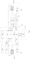
- the means of measuring the geometry comprise an auscultation computer (E3) with a microcontroller (E4) and an FPGA (E9) connected thereto, both located inside an electronic box (G4) arranged in the vehicle.
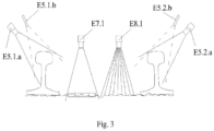
- These means of measuring the geometry of this auscultation system also comprise a first artificial vision device (E5) arranged on the lower part of the vehicle and consisting of two measurement units (E5.1, E5.2) each associated with one of the rails of the track respectively.
- a first artificial vision device E5
- E5.1, E5.2 two measurement units
- Each measurement unit (E5.1, E5.2) of the first vision device (E5) comprises at least one video camera (E5.1.a, E5.2.a) with visual access to at least the outer side of the corresponding rail and a linear projection laser (E5.1.b, E5.2.b).
- Each camera is connected to the FPGA (E9) of the electronics box, for efficient processing of the acquired images.
- the projection laser (E5.1.b, E5.2.b) of each measurement unit (E5.1, E5.2) of the first vision device (E5) is arranged such that it perfectly illuminates the profile of the corresponding rail of the rail to be reconstructed, so that the video camera (E5.1.a, E5.2.a) associated with said rail can perfectly capture the same.
- the application of the automated actuation procedure of the system auscultation computer software (E3) allows the 3D reconstruction of the rail to know the position of each of the points that make up its profile.
- the at least inertial measurement unit (E2) is connected to the microcontroller (E4) with a digital communication, which in this embodiment is formed by a serial port (C2), while the at least one odometry device (E1) is likewise connected to the microcontroller (E4).
- the system comprises an odometry device (E1) and two inertial measurement units (E2), each one associated to a rail.
- this said odometry device (E1) is formed by at least one magnetic sensor connected to the microcontroller (E4) by means of a data transmission connection (C5) and magnets coupled to the vehicle wheels for measuring the instantaneous angular velocity of the same.
- the odometry device (E1) may consist of a tachogenerator, a rotary encoder, a magnetic field detector that measures the presence of magnets previously installed in known positions on the wheel, or a similar device.
- the microcontroller (E4) is responsible for synchronizing (C1) the inertial sensors of the two inertial measurement units (E2) of this system, of the odometry device (E1) and of the measurement units (E5.1, E5. 2) of the first vision device (E5) and is in turn connected to the auscultation computer (E3), whose software, with an actuation algorithm enabled in it, allows the storage, processing and combination of the information received, as well as the transmission of the data.
- the means of measuring the geometry of this auscultation system comprise an electronic control device (E6), with a user actuation interface, connected to the auscultation computer (E3) by means of connection means.
- Said electronic control device (E6) makes it possible to control the auscultation, visualize camera images or data graphs, and calculate the dynamics of the equipment.
- the means of measuring the geometry comprise a second vision device (E7) consisting of a camera or event camera (E7.1), for obtaining the longitudinal and lateral displacement of the vehicle by searching for patterns in the image, which are matched between successive images, this camera being arranged focusing on the ground and, connected to the auscultation computer (E3), by means of a serial port (C2).
- a second vision device E7 consisting of a camera or event camera (E7.1)
- E7.1 for obtaining the longitudinal and lateral displacement of the vehicle by searching for patterns in the image, which are matched between successive images, this camera being arranged focusing on the ground and, connected to the auscultation computer (E3), by means of a serial port (C2).
- This second vision device (E7) allows to obtain signals in longitudinal and lateral positions, measured directly by artificial vision methods. For this purpose, a series of consecutive photographs are taken which allow, through the detection of some characteristics of each photograph taken and by matching these characteristics between the photographs taken, to appreciate between one image and the next, what has been the lateral and longitudinal displacement of the vehicle with respect to the rail.
- the camera (E7.1) of the second vision device (E7) for obtaining the longitudinal and lateral displacement of the vehicle is further connected to the microcontroller (E4) for precise hardware synchronization.
- the microcontroller (E4) for precise hardware synchronization.
- At least one video camera (E5.1.a, E5.2.a) of each measurement unit (E5.1, E5.2) of the first artificial vision device (E5) is connected to the auscultation computer (E3) and to the microcontroller (E4), for the same purpose of synchronization of the data obtained therefrom.
- the auscultation computer (E3) may be responsible for both image processing and image storage, however, in this preferred embodiment of the invention, as shown in Figure 1 , the at least one video camera (E5.1.a, E5.2.a) of each measurement unit (E5.1, E5.2) of the first artificial vision device (E5) is connected to an FPGA (E9) of the system, which in this case is in charge of the processing of the images that are subsequently stored by the auscultation computer (E3).
- Said connection to the FPGA (E9) is in this case an Ethernet channel connection (C3), but in other embodiments it may be a PCI connection.
- the means of measuring the geometry comprise a third vision device (E8) consisting of a depth camera (E8.1) for measurement of the vehicle roll angle and vertical displacement, connected to the auscultation computer (E3), via a wired internet connection or Ethernet channel (C3).
- said third vision device (E8) is also connected to the microcontroller, for a synchronization (C1) of the imaging acquisition with the data from the rest of the sensors.
- this third vision device (E8) it is possible to improve the obtained position and orientation data compared to the values collected by the two inertial measurement units (E2).
- the objective of this camera (E8.1) is the measurement of the relative orientation of the vehicle relative to the rail and the vertical displacement of the vehicle, not being possible to obtain these data from the second vision device (E7).
- each measurement unit (E5.1, E5.2) of the first vision device (E5) is arranged in a first and second modules (G1, G2) closed and watertight respectively.
- the second vision device (E7) and the third vision device (E8) are both arranged inside a third module (G3) which is also closed and watertight.
- they may each be arranged in the first and second closed modules (G1, G2), together with the laser and at least one video camera of a measurement unit (E5.1 , E5.2) of the first vision device (E5) respectively, or even both together in one of said first or second modules (G1, G2).
- the system comprises an additional closed and watertight module (G5) located on the lower part of the vehicle toward the outside, inside which the odometry device (E1) is located.
- the inertial measurement units (E2) in this embodiment are each arranged in the first and second modules (G1, G2) respectively, next to a measurement unit (E5.1, E5.2) of the first device (E5).
- the second vision device (E7) and/or the third vision device (E8) are also arranged in this additional enclosed module (G5) next to the odometry device (E1), even the inertial measurement units (E2) may also be arranged in this additional module (G5).
- any of said second and/or third vision device (E7, E8) are located in at least one of the first and second enclosed modules (G1, G2) in which a laser (E5.1.b, E5.2.b) and the at least one video camera (E5.1.a, E5.2.a) of a measurement unit (E5.1, E5.2.) of the first vision device (E5) are located.
- any of the first, second and third enclosed modules (G1, G2, G3) and the additional enclosed module (G5) must meet requirements in terms of sealing and protection of the electronics and sensors inside, against soiling or impact from any small body which, in the course of the journey, may change the relative position of the components to each other or alter the operation of the components.
- protective covers composed of 1 mm steel plate are fitted, welded to the camera assembly, and there is also a methacrylate plate that allows image capture and laser emission.
- the cables of these elements are inserted inside the square and rectangular profiles so that they are protected.
- the means of connecting the electronic control device (E6) with the auscultation computer (E3) consist of a wireless network via Wi-Fi (C4).
- it also has a wired connection via an Ethernet channel (C3), for greater security in the event of a possible failure of the wireless network.
- it may have only one of these types of means of connection, either via wireless network or via Ethernet.
- the different equipment forming part of the geometry measurement system must have a certain power supply according to their physical characteristics in order to have a certain power available to properly operate.
- This power is supplied by a global power system (E10), which is responsible for distributing the general power supply among all the equipment as appropriate and may or may not have an uninterruptible power supply system that prevents voltage drops in the event of unstable input power.
- This input power is supplied to the overall power system (E10) via mains (E11) in this case, but in other embodiments it may be supplied via batteries.
- a rail auscultation procedure is also proposed in this specification, by means of an onboard rail auscultation system as defined above.
- This procedure comprises a first phase of switching on the auscultation computer (E3) and the electronic control device (E6), as well as the self-calibration of the sensors used and a second phase of data measurement request and activation of the sensors of the system formed by at least one odometry device (E1), at least one inertial measurement unit (E2) and, associated to each rail, a measurement unit (E5.1, E5.2) of a first artificial vision device (E5), consisting of a laser (E5.1.b., E5.2.b.) and at least one video camera (E5.1.a, E5.2.a).
- the system proposed herein features an odometry device (E1) and two inertial measurement units (E2).
- a third phase is carried out, consisting of the processing (P) of the data obtained by means of these sensors by means of the algorithm enabled in the software of the auscultation computer (E3).
- This third phase represented in Figure 2 , comprises the execution steps that are determined below.
- the first step consists of obtaining a kinematic simulation (P1) of the vehicle by means of a first combination (P11) of the known values of the projected geometry (P12) of the rail with the values obtained by the odometry device (E1).
- the second step is to obtain a corrected longitudinal position (P2) of the vehicle on the rail by a second combination (P21) of the kinematic simulation (P1) with the values obtained in the two inertial measurement units (E2) of this system, and an adjustment of the odometry (P13) from the values of the odometry device (E1), wherein said obtained values are formed at least by the value of the angular velocity of the vehicle on the vertical axis.
- the use of the inertial measurement units (E2) is used to obtain the vehicle orientation, but in this procedure it is possible to use them to improve the positioning of the vehicle on the rail, because by combining the values obtained in at least one inertial measurement unit (E2), with the kinematic simulation (P1), an odometry adjustment is performed to obtain the corrected longitudinal position of the vehicle (P2).
- the third stage consists of obtaining the orientation correction values (P3) by means of a third combination (P31) in this case, of the kinematic simulation (P1) which gives information of the reference orientation and kinematics of the vehicle, with the corrected longitudinal position (P2).
- An uncorrected vehicle orientation (P32) obtained from the measurements of the inertial measurement unit (E2) is also combined in this case.
- a fourth stage consists of obtaining the geometric values (P4) of the irregular rail by means of a fourth combination (P41) of the orientation correction values (P3) with the inertial measurements of the two inertial measurement units (E2) and with the data obtained by the measurement units (E5.1, E5.2) of the first artificial vision device (E5).
- the procedure presents a fourth step consisting of the successive sending of the processed data to the electronic control device (E6).
- the means for measuring the geometry of the onboard auscultation system comprise a second vision device (E7) for obtaining the longitudinal and lateral displacement (P5) by means of comparison between successive images of these values of longitudinal and lateral displacement of the rail vehicle.
- the fourth stage consisting of obtaining the geometrical values (P4) of the irregular rail comprises the additional combination (P42) of these values of the longitudinal and lateral displacement of the rail vehicle.
- the means of measuring the geometry of the onboard auscultation system comprise a third vision device (E8).
- the third stage of data processing (P) comprises an additional step of acquisition of the vehicle vertical position and warpage values (P6).
- the third stage of obtaining the values of correction of the orientation (P3) comprises the additional combination (P33) of these vertical position and warp values of the vehicle.
Landscapes
- Engineering & Computer Science (AREA)
- Physics & Mathematics (AREA)
- General Physics & Mathematics (AREA)
- Mechanical Engineering (AREA)
- Computer Vision & Pattern Recognition (AREA)
- Theoretical Computer Science (AREA)
- Structural Engineering (AREA)
- Civil Engineering (AREA)
- Architecture (AREA)
- Health & Medical Sciences (AREA)
- Biomedical Technology (AREA)
- General Health & Medical Sciences (AREA)
- Quality & Reliability (AREA)
- Length Measuring Devices By Optical Means (AREA)
Applications Claiming Priority (2)
| Application Number | Priority Date | Filing Date | Title |
|---|---|---|---|
| ES202030684A ES2890457B2 (es) | 2020-07-02 | 2020-07-02 | Sistema embarcado de auscultación de vías |
| PCT/ES2021/070485 WO2022003230A1 (fr) | 2020-07-02 | 2021-07-02 | Système embarqué d'ausculation de voies |
Publications (1)
| Publication Number | Publication Date |
|---|---|
| EP4177130A1 true EP4177130A1 (fr) | 2023-05-10 |
Family
ID=79315601
Family Applications (1)
| Application Number | Title | Priority Date | Filing Date |
|---|---|---|---|
| EP21833923.2A Pending EP4177130A1 (fr) | 2020-07-02 | 2021-07-02 | Système embarqué d'ausculation de voies |
Country Status (4)
| Country | Link |
|---|---|
| EP (1) | EP4177130A1 (fr) |
| DE (1) | DE212021000415U1 (fr) |
| ES (1) | ES2890457B2 (fr) |
| WO (1) | WO2022003230A1 (fr) |
Families Citing this family (2)
| Publication number | Priority date | Publication date | Assignee | Title |
|---|---|---|---|---|
| AT17971U1 (de) * | 2022-05-24 | 2023-09-15 | Plasser & Theurer Export Von Bahnbaumaschinen Gmbh | Schienenfahrzeug und Verfahren zur Erfassung von Gleislagedaten |
| CN116124008B (zh) * | 2023-04-04 | 2023-07-04 | 成都弓网科技有限责任公司 | 一种可拆卸式铁路侵限检测装置及自校准方法 |
Family Cites Families (11)
| Publication number | Priority date | Publication date | Assignee | Title |
|---|---|---|---|---|
| US6681160B2 (en) * | 1999-06-15 | 2004-01-20 | Andian Technologies Ltd. | Geometric track and track/vehicle analyzers and methods for controlling railroad systems |
| ES1062827Y (es) | 2006-04-28 | 2006-11-01 | Sacyr S A | Dispositivo de auscultacion de via |
| US8345099B2 (en) | 2010-01-25 | 2013-01-01 | Ensco | Optical path protection device and method for a railroad track inspection system |
| PL224065B1 (pl) | 2012-05-14 | 2016-11-30 | Politechnika Warszawska | Układ monitorowania stanu i diagnozowania pojazdów szynowych oraz toru |
| EP2784540B1 (fr) | 2013-03-27 | 2016-08-31 | System7-Railsupport GmbH | Procédé et dispositif de détermination de l'état d'usure d'un rail |
| US10000223B2 (en) * | 2015-09-18 | 2018-06-19 | Tech Services Group, LLC | Rail track geometry measurement |
| US10518791B2 (en) * | 2015-10-20 | 2019-12-31 | Sameer Singh | Integrated rail and track condition monitoring system with imaging and inertial sensors |
| RU2652338C1 (ru) | 2017-02-06 | 2018-04-25 | Александр Сергеевич Ададуров | Система для мониторинга и контроля состояния рельсового пути |
| US20180222504A1 (en) * | 2017-02-08 | 2018-08-09 | Intel Corporation | Location based railway anomaly detection |
| NL2018911B1 (en) * | 2017-05-12 | 2018-11-15 | Fugro Tech Bv | System and method for mapping a railway track |
| CN108466635A (zh) | 2018-02-11 | 2018-08-31 | 成都兴联宜科技有限公司 | 一种高速铁路的列车行驶监控预警系统 |
-
2020
- 2020-07-02 ES ES202030684A patent/ES2890457B2/es active Active
-
2021
- 2021-07-02 DE DE212021000415.6U patent/DE212021000415U1/de active Active
- 2021-07-02 WO PCT/ES2021/070485 patent/WO2022003230A1/fr unknown
- 2021-07-02 EP EP21833923.2A patent/EP4177130A1/fr active Pending
Also Published As
| Publication number | Publication date |
|---|---|
| ES2890457A1 (es) | 2022-01-19 |
| WO2022003230A1 (fr) | 2022-01-06 |
| ES2890457B2 (es) | 2024-05-16 |
| DE212021000415U1 (de) | 2023-05-10 |
Similar Documents
| Publication | Publication Date | Title |
|---|---|---|
| US6681160B2 (en) | Geometric track and track/vehicle analyzers and methods for controlling railroad systems | |
| EP4177130A1 (fr) | Système embarqué d'ausculation de voies | |
| US7164975B2 (en) | Geometric track and track/vehicle analyzers and methods for controlling railroad systems | |
| Weston et al. | Perspectives on railway track geometry condition monitoring from in-service railway vehicles | |
| AU2019216197B2 (en) | Rail vehicle and method for surveying a track section | |
| US20120300060A1 (en) | Vision system for imaging and measuring rail deflection | |
| CN102092405B (zh) | 一种轨道曲线参数测量方法及系统装置 | |
| KR101590712B1 (ko) | 운행기록을 이용한 철도차량과 선로 감시시스템 및 방법 | |
| CN101580071A (zh) | 铁路机车车辆运行姿态测量系统 | |
| CN112119188B (zh) | 控制安装在铁路干预车辆上的一个或多个干预工具的集合的方法 | |
| US20230365170A1 (en) | Method and system for determining a target profile of the track to correct the geometry | |
| CN111811428A (zh) | 轨道车辆限界的测量系统 | |
| CN114701543A (zh) | 基于大数据的高精度设备限界检测预警系统及方法 | |
| US20030103216A1 (en) | Device and process for measuring ovalization, buckling, planes and rolling parameters of railway wheels | |
| JP7089063B2 (ja) | 位置検出装置及び方法 | |
| JP7020324B2 (ja) | 線路曲率推定装置及び方法 | |
| KR102534613B1 (ko) | 레이저 스캔을 통한 레일 음향 러프니스 측정 장치 및 방법 | |
| Antognoli et al. | Requirement specifications for track measuring and monitoring systems//Specifiche di requisiti per sistemi di misura e monitoraggio del binario | |
| DE19957494C1 (de) | Verfahren und Vorrichtung zur Inspektion von Schienen und Gleisbett | |
| EP4339581A1 (fr) | Système et procédé d'inspection visuelle automatisée d'un train de roulement d'un véhicule tel qu'un train et utilisation associée | |
| CA2474757C (fr) | Analyseurs de voie/vehicule et procedes de commande de systeme de voie ferreeanalyseurs de voie/vehicule et procedes de commande de systeme de voie ferree | |
| Escalona | A methodology for the measurement of track geometry based on computer vision and inertial sensors | |
| CA2489980C (fr) | Analyseurs de voies/vehicules et methodes de controle de reseaux ferroviaires | |
| Escalona Franco et al. | A Track Geometry Measuring System Based on Multibody Kinematics, Inertial Sensors and Computer Vision | |
| KR20220143473A (ko) | 이동식 철로시설 점검 시스템 |
Legal Events
| Date | Code | Title | Description |
|---|---|---|---|
| STAA | Information on the status of an ep patent application or granted ep patent |
Free format text: STATUS: THE INTERNATIONAL PUBLICATION HAS BEEN MADE |
|
| PUAI | Public reference made under article 153(3) epc to a published international application that has entered the european phase |
Free format text: ORIGINAL CODE: 0009012 |
|
| STAA | Information on the status of an ep patent application or granted ep patent |
Free format text: STATUS: REQUEST FOR EXAMINATION WAS MADE |
|
| 17P | Request for examination filed |
Effective date: 20230201 |
|
| AK | Designated contracting states |
Kind code of ref document: A1 Designated state(s): AL AT BE BG CH CY CZ DE DK EE ES FI FR GB GR HR HU IE IS IT LI LT LU LV MC MK MT NL NO PL PT RO RS SE SI SK SM TR |
|
| DAV | Request for validation of the european patent (deleted) | ||
| DAX | Request for extension of the european patent (deleted) |