EP4176770B1 - Antriebssystem für eine linear bewegte ausziehbare möbelkomponente - Google Patents
Antriebssystem für eine linear bewegte ausziehbare möbelkomponente Download PDFInfo
- Publication number
- EP4176770B1 EP4176770B1 EP21206471.1A EP21206471A EP4176770B1 EP 4176770 B1 EP4176770 B1 EP 4176770B1 EP 21206471 A EP21206471 A EP 21206471A EP 4176770 B1 EP4176770 B1 EP 4176770B1
- Authority
- EP
- European Patent Office
- Prior art keywords
- guide roller
- drive system
- rail
- pulling means
- roller
- Prior art date
- Legal status (The legal status is an assumption and is not a legal conclusion. Google has not performed a legal analysis and makes no representation as to the accuracy of the status listed.)
- Active
Links
Images
Classifications
-
- A—HUMAN NECESSITIES
- A47—FURNITURE; DOMESTIC ARTICLES OR APPLIANCES; COFFEE MILLS; SPICE MILLS; SUCTION CLEANERS IN GENERAL
- A47B—TABLES; DESKS; OFFICE FURNITURE; CABINETS; DRAWERS; GENERAL DETAILS OF FURNITURE
- A47B88/00—Drawers for tables, cabinets or like furniture; Guides for drawers
- A47B88/40—Sliding drawers; Slides or guides therefor
- A47B88/453—Actuated drawers
- A47B88/457—Actuated drawers operated by electrically-powered actuation means
-
- F—MECHANICAL ENGINEERING; LIGHTING; HEATING; WEAPONS; BLASTING
- F16—ENGINEERING ELEMENTS AND UNITS; GENERAL MEASURES FOR PRODUCING AND MAINTAINING EFFECTIVE FUNCTIONING OF MACHINES OR INSTALLATIONS; THERMAL INSULATION IN GENERAL
- F16H—GEARING
- F16H19/00—Gearings comprising essentially only toothed gears or friction members and not capable of conveying indefinitely-continuing rotary motion
- F16H19/02—Gearings comprising essentially only toothed gears or friction members and not capable of conveying indefinitely-continuing rotary motion for interconverting rotary or oscillating motion and reciprocating motion
- F16H19/06—Gearings comprising essentially only toothed gears or friction members and not capable of conveying indefinitely-continuing rotary motion for interconverting rotary or oscillating motion and reciprocating motion comprising flexible members, e.g. an endless flexible member
- F16H2019/0681—Gearings comprising essentially only toothed gears or friction members and not capable of conveying indefinitely-continuing rotary motion for interconverting rotary or oscillating motion and reciprocating motion comprising flexible members, e.g. an endless flexible member the flexible member forming a closed loop
- F16H2019/0686—Gearings comprising essentially only toothed gears or friction members and not capable of conveying indefinitely-continuing rotary motion for interconverting rotary or oscillating motion and reciprocating motion comprising flexible members, e.g. an endless flexible member the flexible member forming a closed loop the flexible member being directly driven by a pulley or chain wheel
Definitions
- the present invention relates to a drive system for a linearly moving pull-out furniture component of a piece of furniture, in particular for a pull-out drawer of a medicine cabinet, according to the preamble of independent claim 1.
- a drive system has a stationary component which can be fastened to the piece of furniture, a drive motor and a rail which is linearly movable in a pull-out direction relative to the stationary component and which has a rotatably mounted first deflection roller on a first side of the rail and a rotatably mounted second deflection roller on a second side of the rail, wherein a first traction means which is fastened to the stationary component is placed around the first deflection roller and the second deflection roller and is in contact with an output shaft which can be driven by the drive motor such that the rail can be moved in the pull-out direction by the drive motor.
- a drive system according to the preamble of independent claim 1 is known from US202000345139 A1
- the first traction device is a toothed belt and is attached to the stationary component as well as to a pull-out rail that can be attached to the furniture component and is mounted so that it can move linearly to the rail.
- the first pulley is designed as a gear and at the same time forms the output shaft of the drive motor attached to the rail.
- This means that the drive system can be arranged further forward in the piece of furniture and still ensure that the furniture component can be fully extended.
- connecting the drive system is particularly difficult due to the drive motor moving with it, which makes assembly more difficult and retrofitting drives is complex.
- the object of the present invention is therefore to provide a drive system according to the preamble of independent claim 1, which can be assembled and possibly retrofitted more easily and without any special prior knowledge and at the same time ensures complete extension.
- the drive system should be as compact, quiet, powerful and inexpensive as possible and at the same time meet applicable safety standards, which are specified, for example, by the TÜV.
- the object is solved by the features of independent claim 1. Accordingly, in a generic drive system, the object is achieved according to the invention in that the drive motor is attached to the stationary component and the rail on the first side a rotatably mounted third deflection roller and on the second side a rotatably mounted fourth deflection roller around which a second traction means is arranged such that a movement of the rail in the pull-out direction causes a movement of the second traction means relative to the rail in the pull-out direction, wherein the second traction means can be coupled to the linearly moved pull-out furniture component.
- the solution according to the invention allows the drive system to be installed or retrofitted very easily.
- the stationary component can be installed very far forward in a piece of furniture without a difficult connection of the drive motor.
- an extendable furniture component can be fully extended.
- the two-stage movement generated means that the overall length of the drive system can still be reduced and a drive system with one rail length can be used for several depths of the extendable furniture component.
- the drive system can also compensate for different horizontal or vertical positions of the extendable furniture component due to different positions or loading conditions of the furniture component and the height adjustment of the drive system to the extendable furniture component has a larger tolerance.
- the inventive drive system is only intended to be used to move the extendable furniture component and not to guide and thus absorb the weight load of the furniture component.
- the first traction means and the second traction means can be designed as toothed belts, chains, ropes or a combination of the aforementioned traction means.
- the first deflection roller is rotatably mounted at the end of the first side of the rail and/or the second deflection roller is rotatably mounted at the end of the second side of the rail and/or the third deflection roller is rotatably mounted at the end of the first side of the rail and/or the fourth deflection roller is rotatably mounted at the end of the second side of the rail.
- the first deflection roller and the third deflection roller are arranged on a first side of the rail with respect to the stationary component, with the second deflection roller and the fourth deflection roller being arranged on an opposite second side of the rail with respect to the stationary component.
- the first deflection roller and the second deflection roller must be spaced apart on the rail by a distance that is greater than the sum of the width of the stationary component and the diameter of the first and second deflection rollers.
- the pulleys are arranged in the end area or at the end of the rail. In order to be able to use uniformly long rails for pull-out furniture components of different lengths, for example, the pulleys can be attached closer to the stationary component for short pull-out furniture components than for long pull-out furniture components.
- At least the first deflection roller can be rotatably mounted at the end of the first side of the rail and the second deflection roller can be rotatably mounted at the end of the second side of the rail. Furthermore, the third deflection roller can be rotatably mounted at the end of the first side of the rail and the fourth deflection roller can be rotatably mounted at the end of the second side of the rail.
- the second traction means is attached to the stationary component.
- At least one rotatably mounted first tensioning roller is arranged on the stationary component next to the output shaft, wherein the first traction means is placed around the first tensioning roller and the output shaft in such a way that the movement of the output shaft can be transferred to the first traction means without slippage. This ensures that the movement of the output shaft can be completely transferred to the first traction means and thus to the rail.
- the position of the first tension roller relative to the output shaft is adjustable. By adjusting the position of the first tension roller relative to the output shaft, fine adjustment can be made.
- a rotatably mounted second tension pulley is arranged on the stationary component next to the first tension pulley, with the first traction means being arranged in a loop along the first tension pulley, around the output shaft and along the second tension pulley.
- the first traction means first runs along the first tension pulley, then between the first tension pulley and the output shaft, then around the output shaft, then between the output shaft and the second tension pulley and finally along the second tension pulley.
- the second tension pulley increases the angle of the wrap of the first traction means around the output shaft. This allows a higher force to be transferred from the output shaft to the first traction means, whereby a higher tensile force is achieved equally in both directions.
- the output shaft is driven by the drive motor via a gear, the drive motor being an electric motor.
- the drive motor being an electric motor.
- the first deflection roller and the third deflection roller as well as the second deflection roller and the fourth deflection roller are each mounted so that they can rotate independently of one another. This also simplifies the structure of the drive system and enables efficient power transmission. If the roller diameters are different, separate bearings are necessary. If the first and third deflection rollers and the second and fourth deflection rollers have the same diameter, the first and third deflection rollers and the second and fourth deflection rollers can each have a common bearing.
- the circumferences of the third deflection roller and the fourth deflection roller protrude beyond the rail and the stationary component. In this way, a particularly simple and efficient horizontal and vertical height compensation can be achieved. at a point on the second traction means at which the second traction means can be coupled to the extendable furniture component, so that the different positions and loading conditions of the furniture component do not have a negative effect on the drive system.
- the stationary component has a tensioning element with which the tension of the second traction means can be adjusted. This allows the movement of the second traction means generated by the movement of the rail to be transmitted to the attachable furniture component without play.
- the tensioning element is preferably placed on the stationary component in an easily accessible manner. This can simplify assembly.
- the stationary component has a carriage, wherein at least one end of the second traction means is attached to the carriage and wherein, in addition to the tension of the second traction means, the position of the carriage can also be adjusted via the tensioning element, wherein a suspension of the first tension roller is arranged on the carriage in such a way that the position of the first tension roller can be adjusted via the position of the carriage, whereby the contact pressure of the first traction means on the output shaft can be adjusted and the play of the first traction means and the second traction means can be reduced.
- the play of the first and second traction means can thus be removed via an easily accessible mechanism, so that an advantageous transmission of the power of the drive motor via the first traction means and the second traction means to the attachable furniture component takes place.
- the second traction means is a cable. This allows the horizontal and vertical height compensation to be implemented particularly advantageously with regard to different positions and loading states of the furniture component.
- a coupling element is attached to the second traction means, which can be coupled to the linearly moving pull-out furniture component.
- the coupling element can be fixed at different positions on the second traction means or at different positions on the linearly moving pull-out furniture component.
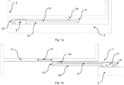
- FIGS 1 to 6 show an embodiment of a drive system 1 according to the invention, wherein the Figures 1a and b show the drive system 1 in interaction with a piece of furniture 2 and a linearly extendable furniture component 3.
- Figure 1a the drive system 1 and the extendable furniture component 3 in a retracted position
- Figure 1b the drive system 1 and the extendable furniture component 3 in an extended position, wherein the extendable furniture component 3 can be moved completely out of the piece of furniture 2 in an extension direction 4 by the drive system 1.
- the extendable furniture component can be, for example, a pull-out drawer, for example of a medicine cabinet, or a table top or a storage area.
- the drive system 1 is only intended to be used to move the pull-out furniture component 3 and not to guide and thus to absorb the weight load of the pull-out furniture component 3. Any guide rails for the purpose of guiding or absorbing the weight load are not shown in the figures.
- the embodiment of the drive system 1 according to the invention shown in the figures has, among other things, a stationary component 5 which can be screwed onto the piece of furniture 2, for example.
- a rail 6 which is linearly movable in the pull-out direction 4 is mounted on the stationary component 5.
- a first deflection roller 7 and a third deflection roller 9 are arranged coaxially and rotatably mounted in an end region on a first side of the rail 6.
- a second deflection roller 8 and a fourth deflection roller 10 are arranged coaxially and rotatably mounted in an end region on a second side of the rail 6.
- the first side of the rail 6 is arranged on one side of the stationary component 5 in relation to the stationary component 5, with the second side of the rail 6 being on the other side of the stationary component 5.
- a first traction means 11 - dashed line - is placed around the first deflection roller 7 and the second deflection roller 8, the ends of which are fastened to the stationary component 5 and which, in this exemplary embodiment, is designed as a toothed belt.
- a drive motor 12 is arranged on the stationary component 5, which drives an output shaft 14 on which a gear 15 is arranged via a gear 13.
- the drive motor 12 is designed as an electric motor.
- On one side of the gear 15 of the output shaft 14, a first tension roller 16 is arranged on a movable carriage 20, and on the other side, a second tension roller 17 is arranged on the stationary component 5.
- the first traction means 11 is arranged in a loop along the first tension roller 16, around the output shaft 14 and along the second tension roller 17, so that the teeth of the toothed belt of the first traction means 11 engage with the teeth of the gear 15 of the output shaft 14.
- the rail 6 can be moved in the extension direction 4 by the drive motor 12 via the first traction means 11.
- a second traction means 18 - solid thick line - is placed around the third deflection roller 9 and the fourth deflection roller 10, the ends of which are also attached to the stationary component 5.
- a coupling element 19 is attached to the second traction means 18, which can be coupled to the pull-out furniture component 3 and thus transfers the movement of the second traction means 18 in the pull-out direction 4 to the pull-out furniture component 3.
- the circumference of the third deflection roller 9 and the fourth deflection roller 10 is larger than the circumference of the first and second deflection rollers 7, 8 and protrudes beyond the rail 6 and on one side beyond the stationary component 5 in the plane in which the third and fourth deflection rollers 9, 10 lie.
- the second traction means 18 and in particular the coupling element 19 have some free space in the vertical and horizontal direction, so that the drive system 1 has the possibility of horizontal and vertical height compensation of the coupling element 19 and different positions and loading states of the pull-out furniture component 3 do not negatively affect the drive system 1.
- the second traction means 18 is designed as a cable, whereby the horizontal and vertical height compensation can be further improved.
- the embodiment of the drive system 1 shown also has a tensioning mechanism that makes it easy to tension both the first traction means 11 and the second traction means 18 and to remove the play in the traction means 11, 18.
- a carriage 20 that can be moved in the pull-out direction 4 is arranged on the stationary component 5, to which one end of the second traction means 18 is fastened.
- the other end of the second traction means 18 is fastened to a tensioning element 21 that is also arranged on the stationary component 5 and via which the tension on the second traction means 18 and at the same time the position of the carriage 20 can be adjusted.
- the tensioning element 21 is designed as a nut that can adjust the tension by screwing it in or out.
- the first tension roller 16 is mounted on the carriage 20, so that the position of the first tension roller 16 can also be adjusted by the position of the carriage 20 and thus the tension of the first traction means 11 and the pressure of the first tension roller 16 on the first traction means 11 on the output shaft 14 can be adjusted.
- the embodiment of the drive system 1 according to the invention shown is therefore particularly easy to install, since the stationary component 5 can be arranged far forward in the piece of furniture 2 and the stationary drive motor 12 can be easily connected.
- no complex height adjustment of the coupling element 19 is required, since efficient vertical and horizontal height compensation is provided by the drive system 1.
- the adjustment of the first and second traction means 11, 18 for efficient power transmission can also be carried out from the front via the tensioning element 21.
Landscapes
- Transmission Devices (AREA)
Description
- Die vorliegende Erfindung bezieht sich auf ein Antriebssystem für eine linear bewegte ausziehbare Möbelkomponente eines Möbelstücks, insbesondere für eine ausziehbare Schublade eines Apothekerschranks, gemäß dem Oberbegriff des unabhängigen Anspruchs 1.
- Ein Antriebssystem nach dem Oberbegriff des unabhängigen Anspruchs 1 weist dabei eine stationäre Komponente, welche an dem Möbelstück befestigbar ist, einen Antriebsmotor und eine gegenüber der stationären Komponente in einer Ausziehrichtung linear bewegliche Schiene auf, welche an einer ersten Seite der Schiene eine drehbar gelagerte erste Umlenkrolle und an einer zweiten Seite der Schiene eine drehbar gelagerte zweite Umlenkrolle aufweist, wobei ein erstes Zugmittel, das an der stationären Komponente befestigt ist, derart um die erste Umlenkrolle und die zweite Umlenkrolle gelegt ist und mit einer vom Antriebsmotor antreibbaren Abtriebswelle in Kontakt ist, dass die Schiene in Ausziehrichtung durch den Antriebsmotor bewegbar ist.
- Ein Antriebssystem nach dem Oberbegriff des unabhängigen Anspruchs 1 ist aus der
US 202000345139 A1 - Die Aufgabe der vorliegenden Erfindung besteht daher darin, ein Antriebssystem gemäß dem Oberbegriff des unabhängigen Anspruchs 1 bereitzustellen, das einfacher und ohne besondere Vorkenntnisse zu montieren und gegebenenfalls nachzurüsten ist und gleichzeitig ein komplettes Ausfahren gewährleistet. Außerdem soll das Antriebssystem möglichst kompakt, leise, leistungsstark und preiswert sein und gleichzeitig geltende Sicherheitsstandards, welche beispielsweise vom TÜV vorgegeben werden, erfüllen.
- Die Aufgabe wird durch die Merkmale des unabhängigen Anspruchs 1 gelöst. Demnach wird bei einem gattungsgemäßen Antriebssystem die Aufgabe erfindungsgemäß dadurch gelöst, dass der Antriebsmotor an der stationären Komponente befestigt ist und die Schiene an der ersten Seite eine drehbar gelagerte dritte Umlenkrolle und an der zweiten Seite eine drehbar gelagerte vierte Umlenkrolle aufweist, um die ein zweites Zugmittel derart angeordnet ist, dass eine Bewegung der Schiene in der Ausziehrichtung eine Bewegung des zweiten Zugmittels relativ zur Schiene in der Ausziehrichtung bedingt, wobei das zweite Zugmittel mit der linear bewegten ausziehbaren Möbelkomponente koppelbar ist.
- Durch die erfindungsgemäße Lösung kann das Antriebssystem sehr einfach montiert oder nachgerüstet werden. Die stationäre Komponente kann sehr weit vorne in einem Möbelstück ohne einen schwierigen Anschluss des Antriebsmotors montiert werden. Gleichzeitig kann eine ausziehbare Möbelkomponente vollständig ausgefahren werden. Dabei kann durch die erzeugte zweistufige Bewegung die Gesamtlänge des Antriebssystems trotzdem reduziert werden und ein Antriebssystem mit einer Schienenlänge kann für mehrere Tiefen der ausziehbaren Möbelkomponente verwendet werden. Außerdem kann durch die Verwendung eines zweiten Zugmittels, das mit der ausziehbaren Möbelkomponente koppelbar ist, das Antriebssystem auch verschiedene horizontale oder vertikale Lagen der ausziehbaren Möbelkomponente aufgrund von unterschiedlichen Positionen oder Beladungszuständen der Möbelkomponente ausgleichen und die Höheneinstellung des Antriebssystems zur ausziehbaren Möbelkomponente hat eine größere Toleranz. Hierbei ist klarzustellen, dass das erfinderische Antriebssystem nur zur Bewegung der ausziehbaren Möbelkomponente und nicht zur Führung und somit der Aufnahme der Gewichtslast der Möbelkomponente genutzt werden soll.
- Erfindungsgemäß können das erste Zugmittel und das zweite Zugmittel als Zahnriemen, Ketten, Seile oder eine Kombination der genannten Zugmittel ausgebildet sein.
- Vorteilhafte Ausgestaltungen der vorliegenden Erfindung sind Gegenstand der Unteransprüche.
- In einer besonders bevorzugten Ausführungsform der vorliegenden Erfindung ist die erste Umlenkrolle am Ende der ersten Seite der Schiene drehbar gelagert und/oder die zweite Umlenkrolle am Ende der zweiten Seite der Schiene drehbar gelagert und/oder die dritte Umlenkrolle am Ende der ersten Seite der Schiene drehbar gelagert und/oder die vierte Umlenkrolle am Ende der zweiten Seite der Schiene drehbar gelagert.
- Die erste Umlenkrolle und die dritte Umlenkrolle sind in Bezug auf die stationäre Komponente auf einer ersten Seite der Schiene angeordnet, wobei die zweite Umlenkrolle und die vierte Umlenkrolle in Bezug auf die stationäre Komponente auf einer gegenüberliegenden zweiten Seite der Schiene angeordnet sind. Die erste Umlenkrolle und die zweite Umlenkrolle müssen dabei auf der Schiene einen Abstand zueinander aufweisen, der größer als die Summe der Breite der stationären Komponente und des Durchmessers der ersten und zweiten Umlenkrollen ist. Gleiches gilt für die dritte Umlenkrolle und vierte Umlenkrolle. Um einen möglichst gossen Fahrweg durch das Antriebssystem für die ausziehbare Möbelkomponente zu erreichen, sind die Umlenkrollen im Endbereich oder am Ende der Schiene angeordnet. Um beispielsweise für verschieden lange ausziehbare Möbelkomponenten einheitlich lange Schienen verwenden zu können, können die Umlenkrollen bei kurzen ausziehbaren Möbelkomponenten näher an der stationären Komponente befestigt werden als bei langen ausziehbaren Möbelkomponenten.
- Dazu kann auch zumindest die erste Umlenkrolle am Ende der ersten Seite der Schiene drehbar gelagert sein und die zweite Umlenkrolle am Ende der zweiten Seite der Schiene drehbar gelagert sein. Weiter kann die dritte Umlenkrolle am Ende der ersten Seite der Schiene drehbar gelagert sein und kann die vierte Umlenkrolle am Ende der zweiten Seite der Schiene drehbar gelagert sein.
- In einer weiteren bevorzugten Ausführungsform der vorliegenden Erfindung ist das zweite Zugmittel an der stationären Komponente befestigt. Dadurch kann die durch die Bewegung der Schiene bedingte Bewegung des zweiten Zugmittels relativ zur Schiene in der Ausziehrichtung besonders einfach und kostengünstig bedingt werden.
- Gemäß einer anderen bevorzugten Ausführungsform der Erfindung ist neben der Abtriebswelle zumindest eine drehbar gelagerte erste Spannrolle an der stationären Komponente angeordnet, wobei das erste Zugmittel derart um die erste Spannrolle und die Abtriebswelle gelegt ist, dass die Bewegung der Abtriebswelle ohne Schlupf auf das erste Zugmittel übertragbar ist. Dadurch kann sichergestellt werden, dass die Bewegung der Abtriebswelle auf das erste Zugmittel und damit auf die Schiene vollständig übertragen werden kann.
- Vorteilhafterweise ist die Position der ersten Spannrolle zur Abtriebswelle einstellbar. In dem die Position der ersten Spannrolle zur Abtriebswelle einstellbar ist, kann hierbei noch eine Feinjustierung erfolgen.
- Besonders bevorzugt ist neben der ersten Spannrolle eine drehbar gelagerte zweite Spannrolle an der stationären Komponente angeordnet, wobei das erste Zugmittel schleifenförmig entlang der ersten Spannrolle, um die Abtriebswelle und entlang der zweiten Spannrolle angeordnet ist. Das heißt, dass das erste Zugmittel erst entlang der ersten Spannrolle, dann zwischen der ersten Spannrolle und der Abtriebswelle, dann um die Abtriebswelle, dann zwischen der Abtriebswelle und der zweiten Spannrolle und schließlich entlang der zweiten Spannrolle verläuft. Durch die zweite Spannrolle wird der Winkel der Umschlingung des ersten Zugmittels um die Abtriebswelle erhöht. Dadurch kann eine höhere Kraft von der Abtriebswelle auf das erste Zugmittel übertragen werden, wodurch eine höhere Zugkraft in beiden Richtungen gleichermaßen erreicht wird.
- Dadurch wird die Übertragung der Bewegung der Abtriebswelle auch bei hohen Gewichten der Möbelkomponente gewährleistet.
- In einer anderen bevorzugten Ausführungsform der vorliegenden Erfindung ist die Abtriebswelle über ein Getriebe durch den Antriebsmotor angetrieben, wobei der Antriebsmotor ein Elektromotor ist. Durch die Verwendung eines Getriebes und eines Elektromotors kann ein ausreichend hohes Drehmoment auch für schwere Möbelkomponenten gewährleistet werden. Der Elektromotor ist dabei sehr kompakt, leise und kann in der stationären Form auch gut von Leihen angeschlossen werden. Durch die erfindungsgemäße Verwendung eines ersten Zugmittels und zweiten Zugmittels benötigt das Getriebe auch keine höhere Umsetzung.
- In einer weiteren bevorzugten Ausführungsform der vorliegenden Erfindung ist das erste Zugmittel ein Zahnriemen und die Abtriebswelle weist ein Zahnrad auf, wobei der Zahnriemen mit dem Zahnrad in Eingriff steht. Dadurch kann die Kraftübertragung von der Abtriebswelle auf das erste Zugmittel noch weiter verbessert werden.
- Gemäß einer weiteren besonders bevorzugten Ausführungsform der vorliegenden Erfindung sind die erste Umlenkrolle und die dritte Umlenkrolle an der ersten Seite der Schiene sowie die zweite Umlenkrolle und die vierte Umlenkrolle an der zweiten Seite der Schiene jeweils koaxial angeordnet. Dadurch kann ein besonders kompakter Aufbau des Antriebssystems erreicht werden. Gleichzeitig können Teile eingespart werden, da zum Beispiel eine gemeinsame Drehachse für zwei Umlenkrollen verwendet werden kann. Gleichzeitig kann bei kompakter Bauweise ein größtmöglicher Auszugsweg bzw. Fahrweg für die linear bewegte ausziehbare Möbelkomponente erreicht werden.
- Vorzugsweise sind die erste Umlenkrolle und die dritte Umlenkrolle sowie die zweite Umlenkrolle und die vierte Umlenkrolle jeweils unabhängig voneinander drehbar gelagert. Auch dies vereinfacht den Aufbau des Antriebssystems und ermöglicht eine effiziente Kraftübertragung. Bei unterschiedlichen Rollendurchmessern ist eine getrennte Lagerung notwendig. Bei gleichem Durchmesser von erster und dritter Umlenkrolle sowie zweiter und vierter Umlenkrolle, können je die erste und dritte Umlenkrolle sowie die zweite und vierte Umlenkrolle eine gemeinsame Lagerung aufweisen.
- In einer anderen bevorzugten Ausführungsform der vorliegenden Erfindung ragen Umfänge der dritten Umlenkrolle und der vierten Umlenkrolle über die Schiene und die stationäre Komponente hinaus. Derart kann ein besonders einfacher und effizienter horizontaler und vertikaler Höhenausgleich an einer Stelle des zweiten Zugmittels, an der das zweite Zugmittel mit der ausziehbaren Möbelkomponente koppelbar ist, ermöglicht werden, sodass die unterschiedlichen Positionen und Beladungszustände der Möbelkomponente das Antriebssystem nicht negativ beeinflussen.
- Vorzugsweise sind die erste Umlenkrolle und die zweite Umlenkrolle mit einem kleineren Umfang als die dritte Umlenkrolle und die vierte Umlenkrolle ausgebildet.
- In einer weiteren besonders bevorzugten Ausführungsform der vorliegenden Erfindung weist die stationäre Komponente ein Spannelement auf, mit dem die Spannung des zweiten Zugmittels einstellbar ist. Damit kann die durch die Bewegung der Schiene erzeugte Bewegung des zweiten Zugmittels ohne Spiel an die anbringbare Möbelkomponente übertragen werden. Vorzugsweise ist das Spannelement gut zugänglich an der stationären Komponente platziert. Dadurch kann die Montage vereinfacht werden.
- In einer besonders bevorzugten Ausführungsform der vorliegenden Erfindung weist die stationäre Komponente einen Schlitten auf, wobei zumindest ein Ende des zweiten Zugmittels an dem Schlitten angebracht ist und wobei neben der Spannung des zweiten Zugmittels auch die Position des Schlittens über das Spannelement einstellbar ist, wobei eine Aufhängung der ersten Spannrolle derart an dem Schlitten angeordnet ist, dass über die Position des Schlittens die Position der ersten Spannrolle einstellbar ist, wobei dadurch der Anpressdruck des ersten Zugmittels auf die Abtriebswelle einstellbar ist und dadurch das Spiel des ersten Zugmittels und des zweiten Zugmittels reduzierbar ist. Damit kann über einen gut zugänglichen Mechanismus das Spiel des ersten und des zweiten Zugmittels herausgenommen werden, sodass eine vorteilhafte Übertragung der Kraft des Antriebsmotors über das erste Zugmittel und das zweite Zugmittel auf die anbringbare Möbelkomponente erfolgt.
- In einer weiteren bevorzugten Ausführungsform der vorliegenden Erfindung ist das zweite Zugmittel ein Seil. Dadurch kann der horizontale und vertikale Höhenausgleich in Bezug auf unterschiedliche Positionen und Beladungszustände der Möbelkomponente besonders vorteilhaft umgesetzt werden.
- Bevorzugter Weise ist ein Kopplungselement an dem zweiten Zugmittel angebracht, das mit der linear bewegten ausziehbaren Möbelkomponente koppelbar ist. Dadurch kann die Kopplung besonders stabil und zuverlässig umgesetzt werden. Ferner kann das Kopplungselement an verschiedenen Positionen auf dem zweiten Zugmittel oder an verschiedenen Positionen an der linear bewegten ausziehbaren Möbelkomponente fixiert werden.
- Nachfolgend wird ein Ausführungsbeispiel der vorliegenden Erfindung anhand von Zeichnungen näher erläutert.
- In den Zeichnungen zeigen:
- Figur 1a, b:
- Draufsichten auf ein Ausführungsbeispiel eines erfindungsgemäßen Antriebssystems in einem Möbelstück und an eine ausziehbare Möbelkomponente gekoppelt in einer eingefahrenen und ausgefahrenen Position der Möbelkomponente,
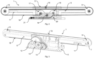
- Figur 2:
- einen vertikalen Schnitt durch das in
Figur 1 gezeigte Ausführungsbeispiel des Antriebssystems in der Ebene des zweiten Zugmittels, - Figur 3:
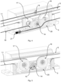
- perspektivische Ansicht auf das in
Figur 1 gezeigte Ausführungsbeispiel des Antriebssystems von der Rückseite und ohne Abdeckung des Antriebsmotors und Getriebes, - Figur 4:
- perspektivische Detaileinsicht auf einen vertikalen Schnitt durch das in
Figur 1 gezeigte Ausführungsbeispiel des Antriebssystems in der Ebene des zweiten Zugmittels, - Figur 5:
- perspektivische Detaileinsicht auf einen vertikalen Schnitt durch das in
Figur 1 gezeigte Ausführungsbeispiel des Antriebssystems in der Ebene des ersten Zugmittels, - Figur 6:
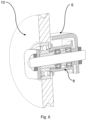
- perspektivische Detailansicht auf einen vertikalen, senkrecht zur Ausziehrichtung angeordneten Schnitt durch die zweite Umlenkrolle, die vierte Umlenkrolle und die Schiene des in
Figur 1 gezeigten Ausführungsbeispiels des Antriebssystems. - In den folgenden Abbildungen sind gleiche Teile mit gleichen Bezugszeichen versehen. Sofern eine Figur Bezugszeichen enthält, auf die in der zugehörigen Figurenbeschreibung nicht explizit eingegangen wird, wird auf vorherige oder nachfolgende Figurenbeschreibungen verwiesen.
- Die
Figuren 1 bis 6 zeigen ein Ausführungsbeispiel eines erfindungsgemäßen Antriebssystems 1, wobei dieFiguren 1a und b das Antriebssystem 1 im Zusammenspiel mit einem Möbelstück 2 und einer linear ausziehbaren Möbelkomponente 3 zeigen. Dabei zeigtFigur 1a das Antriebssystem 1 und die ausziehbare Möbelkomponente 3 in einer eingefahrenen Position undFigur 1b das Antriebssystem 1 und die ausziehbare Möbelkomponente 3 in einer ausgefahrenen Position, wobei die ausziehbare Möbelkomponente 3 durch das Antriebssystem 1 vollständig in einer Ausziehrichtung 4 aus dem Möbelstück 2 gefahren werden kann. Die ausziehbare Möbelkomponente kann zum Beispiel eine ausziehbare Schublade beispielsweise eines Apothekerschranks oder eine Tischplatte oder eine Ablagefläche sein. Es ist nochmals anzumerken, dass das Antriebssystem 1 nur zur Bewegung der ausziehbaren Möbelkomponente 3 und nicht zur Führung und somit der Aufnahme der Gewichtslast der ausziehbaren Möbelkomponente 3 genutzt werden soll. Etwaige Führungsschienen zum Zweck der Führung beziehungsweise Gewichtslastaufnahme sind in den Figuren nicht gezeigt. - Das in den Figuren gezeigte erfindungsgemäße Ausführungsbeispiel des Antriebssystems 1 weist unteranderem eine stationäre Komponente 5 auf, die an das Möbelstück 2 beispielsweise angeschraubt werden kann. An der stationären Komponente 5 ist eine in Ausziehrichtung 4 linear bewegliche Schiene 6 gelagert. An einer ersten Seite der Schiene 6 sind in einem Endbereich eine erste Umlenkrolle 7 und eine dritte Umlenkrolle 9 koaxial und drehbar gelagert angeordnet. An einer zweiten Seite der Schiene 6 sind in einem Endbereich eine zweite Umlenkrolle 8 und eine vierte Umlenkrolle 10 koaxial und drehbar gelagert angeordnet. Die erste Seite der Schiene 6 ist in Bezug zur stationären Komponente 5 auf der einen Seite der stationären Komponente 5 angeordnet, wobei sich die zweite Seite der Schiene 6 auf der anderen Seite der stationären Komponente 5 befindet. Die erste Umlenkrolle 7 und zweite Umlenkrolle 8 können auf der jeweiligen Seite im Endbereich oder am Ende der Schiene 6 angeordnet sein. Die erste Umlenkrolle 7 und die zweite Umlenkrolle 8 müssen dabei einen Abstand auf der Schiene 6 haben, der größer als die Summe der Breite der stationären Komponente 5 und des Durchmessers der ersten und zweiten Umlenkrollen 7, 8 ist. Ebenso müssen die dritte und vierte Umlenkrolle 9, 10 einen Abstand auf der Schiene 6 haben, der größer als die Summe der Breite der stationären Komponente 5 und des Durchmessers der dritten und vierten Umlenkrollen 9,10 ist.
- Um die erste Umlenkrolle 7 und die zweite Umlenkrolle 8 ist ein erstes Zugmittel 11 - gestrichelte Linie - gelegt, dessen Enden an der stationären Komponente 5 befestigt sind und das in diesem Ausführungsbeispiel als Zahnriemen ausgebildet ist. An der stationären Komponente 5 ist ein Antriebsmotor 12 angeordnet, der über ein Getriebe 13 eine Abtriebswelle 14 antreibt, auf der ein Zahnrad 15 angeordnet ist. Der Antriebsmotor 12 ist als Elektromotor ausgebildet. Auf der einen Seite des Zahnrads 15 der Abtriebswelle 14 ist eine erste Spannrolle 16 auf einem beweglichen Schlitten 20 angeordnet und auf der anderen Seite eine zweite Spannrolle 17 an der stationären Komponente 5 angeordnet. Das erste Zugmittel 11 ist schleifenförmig entlang der ersten Spannrolle 16, um die Abtriebswelle 14 und entlang der zweiten Spannrolle 17 angeordnet, sodass die Zähne des Zahnriemens des ersten Zugmittels 11 in die Zähne des Zahnrads 15 der Abtriebswelle 14 greifen. Dadurch kann die Schiene 6 durch den Antriebsmotor 12 über das erste Zugmittel 11 in der Ausziehrichtung 4 bewegt werden.
- Dabei sind um die dritte Umlenkrolle 9 und die vierte Umlenkrolle 10 ein zweites Zugmittel 18 - durchgezogene dicke Linie - gelegt, dessen Enden ebenfalls an der stationären Komponente 5 befestigt sind. Dadurch wird durch eine Bewegung der Schiene 6 in Ausziehrichtung 4 eine Bewegung des zweiten Zugmittels 18 relativ zu Schiene 6 bedingt. An dem zweiten Zugmittel 18 ist dabei ein Kopplungselement 19 angebracht, das mit der ausziehbaren Möbelkomponente 3 koppelbar ist und damit die Bewegung des zweiten Zugmittels 18 in der Ausziehrichtung 4 auf die ausziehbare Möbelkomponente 3 überträgt. Der Umfang der dritten Umlenkrolle 9 und der vierten Umlenkrolle 10 ist dabei größer als der Umfang der ersten und zweiten Umlenkrolle 7, 8 und ragt in der Ebene, in der die dritte und vierte Umlenkrolle 9, 10 liegen, über die Schiene 6 und einseitig über die stationäre Komponente 5 hinaus. Dadurch hat das zweite Zugmittel 18 und insbesondere das Kopplungselement 19 in vertikaler und horizontaler Richtung etwas Freiraum, sodass das Antriebssystem 1 eine Möglichkeit zu einem horizontalen und vertikalen Höhenausgleich des Kopplungselements 19 erreicht und unterschiedliche Positionen und Beladungszustände der ausziehbaren Möbelkomponente 3 das Antriebssystem 1 nicht negativ beeinflussen. In dem gezeigten Ausführungsbeispiel ist das zweite Zugmittel 18 als Seil ausgebildet, wodurch der horizontale und vertikale Höhenausgleich noch verbessert werden kann.
- Das gezeigte Ausführungsbeispiel des Antriebssystems 1 weist außerdem einen Spannmechanismus auf, der in einfacher Weise ermöglicht, sowohl das erste Zugmittel 11 und das zweite Zugmittel 18 zu spannen und das Spiel der Zugmittel 11, 18 herauszunehmen. Dazu ist ein in Ausziehrichtung 4 beweglicher Schlitten 20 an der stationären Komponente 5 angeordnet, an dem ein Ende des zweiten Zugmittels 18 befestigt ist. Das andere Ende des zweiten Zugmittel 18 ist an einem Spannelement 21 befestigt, dass ebenfalls an der stationären Komponente 5 angeordnet ist und über das sich die Spannung auf dem zweiten Zugmittel 18 und gleichzeitig die Position des Schlittens 20 einstellen lässt. In diesem Ausführungsbeispiel ist das Spannelement 21 als eine Mutter ausgebildet, die durch Hinein- oder Herausdrehen die Spannung einstellen kann. Gleichzeitig ist die erste Spannrolle 16 an dem Schlitten 20 gelagert, sodass durch die Position des Schlittens 20 auch die Position der ersten Spannrolle 16 einstellbar ist und damit die Spannung des ersten Zugmittels 11 und der Druck der ersten Spannrolle 16 auf das erste Zugmittel 11 an die Abtriebswelle 14 eingestellt werden kann.
- Das gezeigte Ausführungsbeispiel des erfindungsgemäßen Antriebssystems 1 ist damit besonders einfach zu montieren, da die stationäre Komponente 5 weit vorne in dem Möbelstück 2 angeordnet werden kann und ein einfacher Anschluss des stationären Antriebsmotors 12 erfolgen kann. Außerdem bedarf es keiner aufwendigen Höheneinstellung des Kopplungselement 19, da ein effizienter vertikaler und horizontaler Höhenausgleich durch das Antriebssystem 1 gegeben ist. Die Justierung des ersten und zweiten Zugmittels 11, 18 für eine effiziente Kraftübertragung kann ebenfalls von Vorne über das Spannelement 21 erfolgen.
-
- 1
- Antriebssystem
- 2
- Möbelstück
- 3
- ausziehbare Möbelkomponente
- 4
- Ausziehrichtung
- 5
- stationäre Komponente
- 6
- Schiene
- 7
- erste Umlenkrolle
- 8
- zweite Umlenkrolle
- 9
- dritte Umlenkrolle
- 10
- vierte Umlenkrolle
- 11
- erstes Zugmittel
- 12
- Antriebsmotor
- 13
- Getriebe
- 14
- Abtriebswelle
- 15
- Zahnrad
- 16
- erste Spannrolle
- 17
- zweite Spannrolle
- 18
- zweites Zugmittel
- 19
- Kopplungselement
- 20
- Schlitten
- 21
- Spannelement
Claims (15)
- Antriebssystem (1) für eine linear bewegte ausziehbare Möbelkomponente (3) eines Möbelstücks (2), insbesondere für eine ausziehbare Schublade eines Apothekerschranks, wobei das Antriebssystem (1) eine stationäre Komponente (5), welche an dem Möbelstück (2) befestigbar ist, einen Antriebsmotor (12) und eine gegenüber der stationären Komponente (5) in einer Ausziehrichtung (4) linear bewegliche Schiene (6) aufweist, welche an einer ersten Seite der Schiene (6) eine drehbar gelagerte erste Umlenkrolle (7) und an einer zweiten Seite der Schiene (6) eine drehbar gelagerte zweite Umlenkrolle (8) aufweist, wobei ein erstes Zugmittel (11), das an der stationären Komponente (5) befestigt ist, derart um die erste Umlenkrolle (7) und die zweite Umlenkrolle (8) gelegt ist und mit einer vom Antriebsmotor (12) antreibbaren Abtriebswelle (14) in Kontakt ist, dass die Schiene (6) in Ausziehrichtung (4) durch den Antriebsmotor (12) bewegbar ist, dadurch gekennzeichnet, dass der Antriebsmotor (12) an der stationären Komponente (5) befestigt ist und die Schiene (6) an der ersten Seite eine drehbar gelagerte dritte Umlenkrolle (9) und an der zweiten Seite eine drehbar gelagerte vierte Umlenkrolle (10) aufweist, um die ein zweites Zugmittel (18) derart angeordnet ist, dass eine Bewegung der Schiene (6) in der Ausziehrichtung (4) eine Bewegung des zweiten Zugmittels (18) relativ zur Schiene (6) in der Ausziehrichtung (4) bedingt, wobei das zweite Zugmittel (18) mit der linear bewegten ausziehbaren Möbelkomponente (3) koppelbar ist.
- Antriebssystem (1) nach Anspruch 1, dadurch gekennzeichnet, dass die erste Umlenkrolle (7) am Ende der ersten Seite der Schiene (6) drehbar gelagert ist und/oder die zweite Umlenkrolle (8) am Ende der zweiten Seite der Schiene (6) drehbar gelagert ist und/oder die dritte Umlenkrolle (9) am Ende der ersten Seite der Schiene (6) drehbar gelagert ist und/oder die vierte Umlenkrolle (10) am Ende der zweiten Seite der Schiene (6) drehbar gelagert ist.
- Antriebssystem (1) nach Anspruch 1 oder 2, dadurch gekennzeichnet, dass das zweite Zugmittel (18) an der stationären Komponente (5) befestigt ist.
- Antriebssystem (1) nach Anspruch 1 bis 3, dadurch gekennzeichnet, dass neben der Abtriebswelle (14) zumindest eine drehbar gelagerte erste Spannrolle (16) an der stationären Komponente (5) angeordnet ist, wobei das erste Zugmittel (11) derart um die erste Spannrolle (16) und die Abtriebswelle (14) gelegt ist, dass die Bewegung der Abtriebswelle (14) ohne Schlupf auf das erste Zugmittel (11) übertragbar ist.
- Antriebssystem (1) nach Anspruch 3, dadurch gekennzeichnet, dass die Position der ersten Spannrolle (16) zur Abtriebswelle (14) einstellbar ist.
- Antriebssystem (1) nach Anspruch 4 oder 5, dadurch gekennzeichnet, dass neben der ersten Spannrolle (16) eine drehbar gelagerte zweite Spannrolle (17) an der stationären Komponente (5) angeordnet ist, wobei das erste Zugmittel (11) schleifenförmig entlang der ersten Spannrolle (16), um die Abtriebswelle (14) und entlang der zweiten Spannrolle (17) angeordnet ist.
- Antriebssystem (1) nach einem der Ansprüche 1 bis 6, dadurch gekennzeichnet, dass die Abtriebswelle (14) über ein Getriebe (13) durch den Antriebsmotor (12) angetrieben ist, wobei der Antriebsmotor (12) ein Elektromotor ist.
- Antriebssystem (1) nach einem der Ansprüche 1 bis 7, dadurch gekennzeichnet, dass das erste Zugmittel (11) ein Zahnriemen ist und die Abtriebswelle (14) ein Zahnrad (15) aufweist, wobei der Zahnriemen mit dem Zahnrad (15) in Eingriff steht.
- Antriebssystem (1) nach einem der Ansprüche 1 bis 8, dadurch gekennzeichnet, dass die erste Umlenkrolle (7) und die dritte Umlenkrolle (9) an der ersten Seite der Schiene (6) sowie die zweite Umlenkrolle (8) und die vierte Umlenkrolle (10) an der zweiten Seite der Schiene (6) jeweils koaxial angeordnet sind.
- Antriebssystem (1) nach Anspruch 9, dadurch gekennzeichnet, dass die erste Umlenkrolle (7) und die dritte Umlenkrolle (9) sowie die zweite Umlenkrolle (8) und die vierte Umlenkrolle (10) jeweils unabhängig voneinander drehbar gelagert sind.
- Antriebssystem (1) nach einem der Ansprüche 1 bis 10, dadurch gekennzeichnet, dass Umfänge der dritten Umlenkrolle (9) und der vierten Umlenkrolle (10) über die Schiene (6) und die stationäre Komponente (5) hinausragen.
- Antriebssystem (1) nach einem der Ansprüche 1 bis 11, dadurch gekennzeichnet, dass die erste Umlenkrolle (7) und die zweite Umlenkrolle (8) mit einem kleineren Umfang als die dritte Umlenkrolle (9) und die vierte Umlenkrolle (10) ausgebildet sind.
- Antriebssystem (1) nach einem der Ansprüche 3 bis 12, dadurch gekennzeichnet, dass die stationäre Komponente (5) ein Spannelement (21) aufweist, mit dem die Spannung des zweiten Zugmittels (18) einstellbar ist.
- Antriebssystem (1) nach Anspruch 13, dadurch gekennzeichnet, dass die stationäre Komponente (5) einen Schlitten (20) aufweist, wobei zumindest ein Ende des zweiten Zugmittels (18) an dem Schlitten (20) angebracht ist und wobei neben der Spannung des zweiten Zugmittels (18) auch die Position des Schlittens (20) über das Spannelement (21) einstellbar ist, wobei eine Aufhängung der ersten Spannrolle (16) derart an dem Schlitten (20) angeordnet ist, dass über die Position des Schlittens (20) die Position der ersten Spannrolle (16) einstellbar ist, wobei dadurch der Anpressdruck des ersten Zugmittels (11) auf die Abtriebswelle (14) einstellbar ist und dadurch das Spiel des ersten Zugmittels (11) und des zweiten Zugmittels (18) reduzierbar ist.
- Antriebssystem (1) nach einem der Ansprüche 1 bis 14, dadurch gekennzeichnet, dass ein Kopplungselement (19) an dem zweiten Zugmittel (18) angebracht ist, das mit der linear bewegten ausziehbaren Möbelkomponente (3) koppelbar ist.
Priority Applications (1)
| Application Number | Priority Date | Filing Date | Title |
|---|---|---|---|
| EP21206471.1A EP4176770B1 (de) | 2021-11-04 | 2021-11-04 | Antriebssystem für eine linear bewegte ausziehbare möbelkomponente |
Applications Claiming Priority (1)
| Application Number | Priority Date | Filing Date | Title |
|---|---|---|---|
| EP21206471.1A EP4176770B1 (de) | 2021-11-04 | 2021-11-04 | Antriebssystem für eine linear bewegte ausziehbare möbelkomponente |
Publications (2)
| Publication Number | Publication Date |
|---|---|
| EP4176770A1 EP4176770A1 (de) | 2023-05-10 |
| EP4176770B1 true EP4176770B1 (de) | 2024-05-29 |
Family
ID=78528726
Family Applications (1)
| Application Number | Title | Priority Date | Filing Date |
|---|---|---|---|
| EP21206471.1A Active EP4176770B1 (de) | 2021-11-04 | 2021-11-04 | Antriebssystem für eine linear bewegte ausziehbare möbelkomponente |
Country Status (1)
| Country | Link |
|---|---|
| EP (1) | EP4176770B1 (de) |
Families Citing this family (1)
| Publication number | Priority date | Publication date | Assignee | Title |
|---|---|---|---|---|
| DE102023120668A1 (de) * | 2023-08-03 | 2025-02-06 | Accuride International Gmbh | Zwei-Wege-Auszugsschiene |
Family Cites Families (2)
| Publication number | Priority date | Publication date | Assignee | Title |
|---|---|---|---|---|
| AT504375B1 (de) * | 2006-10-23 | 2010-01-15 | Blum Gmbh Julius | Möbel mit einer antriebsvorrichtung für bewegbare möbelteile |
| WO2019074271A1 (ko) * | 2017-10-12 | 2019-04-18 | (주)세고스 | 슬라이딩 장치 |
-
2021
- 2021-11-04 EP EP21206471.1A patent/EP4176770B1/de active Active
Also Published As
| Publication number | Publication date |
|---|---|
| EP4176770A1 (de) | 2023-05-10 |
Similar Documents
| Publication | Publication Date | Title |
|---|---|---|
| DE69309648T2 (de) | Türöffnungs- und -schliesssystem | |
| EP1645448B2 (de) | Fensterrollo für ein Fahrzeugfenster | |
| DE29919877U1 (de) | Elektromotorische Verstelleinrichtung | |
| DE69305949T2 (de) | Motorisch verstellbare Sitzgleiteinrichtung | |
| EP1462601A2 (de) | Sektionaltor | |
| EP2974623A1 (de) | Elektromotorisch verstellbare stützeinrichtung | |
| EP0581228A1 (de) | Federangetriebener Aufroller für Sicherheitsgurte bei Kraftfahrzeugen | |
| EP0711898A1 (de) | Freitragendes Schiebetor | |
| EP0731040B1 (de) | Knickbares Förderband mit definierter Spannung des Tragorgans | |
| DE60314498T2 (de) | Antriebsmechanismus für einen körper auf schienen | |
| EP2050912A2 (de) | Schienenelement und Torantrieb | |
| EP4176770A1 (de) | Antriebssystem für eine linear bewegte ausziehbare möbelkomponente | |
| EP1584264B1 (de) | Höhenverstellbarer Antrieb, insbesondere für Möbel | |
| DE3213957C2 (de) | Auffahrabschaltung für ein Fahrzeug | |
| WO2019201680A1 (de) | Energieführungskette mit querstück, entsprechende seitenlasche und führungsanordnung hiermit | |
| EP4185510B1 (de) | Feedback-aktuator für eine lenkeinrichtung eines kraftfahrzeugs und lenksäule für ein kraftfahrzeug | |
| EP3538730B1 (de) | Antriebsvorrichtung für ein anzutreibendes element | |
| AT518917B1 (de) | Absturzsicherung | |
| DE19831442C2 (de) | Getriebe für Sitzverstelleinrichtungen in Kraftfahrzeugen | |
| DE102009051194A1 (de) | Lagersystem mit unabhängig spannbaren Antriebsmitteln | |
| DE202006003901U1 (de) | Schiebetüranordnung für ein Kraftfahrzeug | |
| DE1555632A1 (de) | Scheibenfuehrung fuer in den Fensterschacht eines Fahrzeuges versenkbare Schiebefenster | |
| DE3017969C2 (de) | Einrichtung zur Parallelführung der Spanntrommel eines Senkrechtsförderers | |
| DE202005021004U1 (de) | Höhenverstellbarer Antrieb, insbesondere für Möbel | |
| EP1152167A2 (de) | Vorrichtung zum Verstellen von relativ zueinander beweglichen Teilen |
Legal Events
| Date | Code | Title | Description |
|---|---|---|---|
| PUAI | Public reference made under article 153(3) epc to a published international application that has entered the european phase |
Free format text: ORIGINAL CODE: 0009012 |
|
| STAA | Information on the status of an ep patent application or granted ep patent |
Free format text: STATUS: THE APPLICATION HAS BEEN PUBLISHED |
|
| AK | Designated contracting states |
Kind code of ref document: A1 Designated state(s): AL AT BE BG CH CY CZ DE DK EE ES FI FR GB GR HR HU IE IS IT LI LT LU LV MC MK MT NL NO PL PT RO RS SE SI SK SM TR |
|
| STAA | Information on the status of an ep patent application or granted ep patent |
Free format text: STATUS: REQUEST FOR EXAMINATION WAS MADE |
|
| 17P | Request for examination filed |
Effective date: 20231023 |
|
| RBV | Designated contracting states (corrected) |
Designated state(s): AL AT BE BG CH CY CZ DE DK EE ES FI FR GB GR HR HU IE IS IT LI LT LU LV MC MK MT NL NO PL PT RO RS SE SI SK SM TR |
|
| GRAP | Despatch of communication of intention to grant a patent |
Free format text: ORIGINAL CODE: EPIDOSNIGR1 |
|
| STAA | Information on the status of an ep patent application or granted ep patent |
Free format text: STATUS: GRANT OF PATENT IS INTENDED |
|
| INTG | Intention to grant announced |
Effective date: 20240227 |
|
| GRAS | Grant fee paid |
Free format text: ORIGINAL CODE: EPIDOSNIGR3 |
|
| GRAA | (expected) grant |
Free format text: ORIGINAL CODE: 0009210 |
|
| STAA | Information on the status of an ep patent application or granted ep patent |
Free format text: STATUS: THE PATENT HAS BEEN GRANTED |
|
| AK | Designated contracting states |
Kind code of ref document: B1 Designated state(s): AL AT BE BG CH CY CZ DE DK EE ES FI FR GB GR HR HU IE IS IT LI LT LU LV MC MK MT NL NO PL PT RO RS SE SI SK SM TR |
|
| REG | Reference to a national code |
Ref country code: CH Ref legal event code: EP |
|
| REG | Reference to a national code |
Ref country code: IE Ref legal event code: FG4D Free format text: LANGUAGE OF EP DOCUMENT: GERMAN |
|
| REG | Reference to a national code |
Ref country code: DE Ref legal event code: R096 Ref document number: 502021003849 Country of ref document: DE |
|
| REG | Reference to a national code |
Ref country code: LT Ref legal event code: MG9D |
|
| REG | Reference to a national code |
Ref country code: NL Ref legal event code: MP Effective date: 20240529 |
|
| PG25 | Lapsed in a contracting state [announced via postgrant information from national office to epo] |
Ref country code: IS Free format text: LAPSE BECAUSE OF FAILURE TO SUBMIT A TRANSLATION OF THE DESCRIPTION OR TO PAY THE FEE WITHIN THE PRESCRIBED TIME-LIMIT Effective date: 20240929 |
|
| PG25 | Lapsed in a contracting state [announced via postgrant information from national office to epo] |
Ref country code: BG Free format text: LAPSE BECAUSE OF FAILURE TO SUBMIT A TRANSLATION OF THE DESCRIPTION OR TO PAY THE FEE WITHIN THE PRESCRIBED TIME-LIMIT Effective date: 20240529 |
|
| PG25 | Lapsed in a contracting state [announced via postgrant information from national office to epo] |
Ref country code: HR Free format text: LAPSE BECAUSE OF FAILURE TO SUBMIT A TRANSLATION OF THE DESCRIPTION OR TO PAY THE FEE WITHIN THE PRESCRIBED TIME-LIMIT Effective date: 20240529 Ref country code: FI Free format text: LAPSE BECAUSE OF FAILURE TO SUBMIT A TRANSLATION OF THE DESCRIPTION OR TO PAY THE FEE WITHIN THE PRESCRIBED TIME-LIMIT Effective date: 20240529 |
|
| PG25 | Lapsed in a contracting state [announced via postgrant information from national office to epo] |
Ref country code: GR Free format text: LAPSE BECAUSE OF FAILURE TO SUBMIT A TRANSLATION OF THE DESCRIPTION OR TO PAY THE FEE WITHIN THE PRESCRIBED TIME-LIMIT Effective date: 20240830 |
|
| PG25 | Lapsed in a contracting state [announced via postgrant information from national office to epo] |
Ref country code: ES Free format text: LAPSE BECAUSE OF FAILURE TO SUBMIT A TRANSLATION OF THE DESCRIPTION OR TO PAY THE FEE WITHIN THE PRESCRIBED TIME-LIMIT Effective date: 20240529 |
|
| PG25 | Lapsed in a contracting state [announced via postgrant information from national office to epo] |
Ref country code: PL Free format text: LAPSE BECAUSE OF FAILURE TO SUBMIT A TRANSLATION OF THE DESCRIPTION OR TO PAY THE FEE WITHIN THE PRESCRIBED TIME-LIMIT Effective date: 20240529 |
|
| PG25 | Lapsed in a contracting state [announced via postgrant information from national office to epo] |
Ref country code: LV Free format text: LAPSE BECAUSE OF FAILURE TO SUBMIT A TRANSLATION OF THE DESCRIPTION OR TO PAY THE FEE WITHIN THE PRESCRIBED TIME-LIMIT Effective date: 20240529 |
|
| PG25 | Lapsed in a contracting state [announced via postgrant information from national office to epo] |
Ref country code: PL Free format text: LAPSE BECAUSE OF FAILURE TO SUBMIT A TRANSLATION OF THE DESCRIPTION OR TO PAY THE FEE WITHIN THE PRESCRIBED TIME-LIMIT Effective date: 20240529 Ref country code: NO Free format text: LAPSE BECAUSE OF FAILURE TO SUBMIT A TRANSLATION OF THE DESCRIPTION OR TO PAY THE FEE WITHIN THE PRESCRIBED TIME-LIMIT Effective date: 20240829 Ref country code: LV Free format text: LAPSE BECAUSE OF FAILURE TO SUBMIT A TRANSLATION OF THE DESCRIPTION OR TO PAY THE FEE WITHIN THE PRESCRIBED TIME-LIMIT Effective date: 20240529 Ref country code: IS Free format text: LAPSE BECAUSE OF FAILURE TO SUBMIT A TRANSLATION OF THE DESCRIPTION OR TO PAY THE FEE WITHIN THE PRESCRIBED TIME-LIMIT Effective date: 20240929 Ref country code: HR Free format text: LAPSE BECAUSE OF FAILURE TO SUBMIT A TRANSLATION OF THE DESCRIPTION OR TO PAY THE FEE WITHIN THE PRESCRIBED TIME-LIMIT Effective date: 20240529 Ref country code: GR Free format text: LAPSE BECAUSE OF FAILURE TO SUBMIT A TRANSLATION OF THE DESCRIPTION OR TO PAY THE FEE WITHIN THE PRESCRIBED TIME-LIMIT Effective date: 20240830 Ref country code: FI Free format text: LAPSE BECAUSE OF FAILURE TO SUBMIT A TRANSLATION OF THE DESCRIPTION OR TO PAY THE FEE WITHIN THE PRESCRIBED TIME-LIMIT Effective date: 20240529 Ref country code: ES Free format text: LAPSE BECAUSE OF FAILURE TO SUBMIT A TRANSLATION OF THE DESCRIPTION OR TO PAY THE FEE WITHIN THE PRESCRIBED TIME-LIMIT Effective date: 20240529 Ref country code: BG Free format text: LAPSE BECAUSE OF FAILURE TO SUBMIT A TRANSLATION OF THE DESCRIPTION OR TO PAY THE FEE WITHIN THE PRESCRIBED TIME-LIMIT Effective date: 20240529 Ref country code: RS Free format text: LAPSE BECAUSE OF FAILURE TO SUBMIT A TRANSLATION OF THE DESCRIPTION OR TO PAY THE FEE WITHIN THE PRESCRIBED TIME-LIMIT Effective date: 20240829 |
|
| PG25 | Lapsed in a contracting state [announced via postgrant information from national office to epo] |
Ref country code: NL Free format text: LAPSE BECAUSE OF FAILURE TO SUBMIT A TRANSLATION OF THE DESCRIPTION OR TO PAY THE FEE WITHIN THE PRESCRIBED TIME-LIMIT Effective date: 20240529 |
|
| PG25 | Lapsed in a contracting state [announced via postgrant information from national office to epo] |
Ref country code: NL Free format text: LAPSE BECAUSE OF FAILURE TO SUBMIT A TRANSLATION OF THE DESCRIPTION OR TO PAY THE FEE WITHIN THE PRESCRIBED TIME-LIMIT Effective date: 20240529 |
|
| PG25 | Lapsed in a contracting state [announced via postgrant information from national office to epo] |
Ref country code: DK Free format text: LAPSE BECAUSE OF FAILURE TO SUBMIT A TRANSLATION OF THE DESCRIPTION OR TO PAY THE FEE WITHIN THE PRESCRIBED TIME-LIMIT Effective date: 20240529 |
|
| PG25 | Lapsed in a contracting state [announced via postgrant information from national office to epo] |
Ref country code: EE Free format text: LAPSE BECAUSE OF FAILURE TO SUBMIT A TRANSLATION OF THE DESCRIPTION OR TO PAY THE FEE WITHIN THE PRESCRIBED TIME-LIMIT Effective date: 20240529 |
|
| PG25 | Lapsed in a contracting state [announced via postgrant information from national office to epo] |
Ref country code: CZ Free format text: LAPSE BECAUSE OF FAILURE TO SUBMIT A TRANSLATION OF THE DESCRIPTION OR TO PAY THE FEE WITHIN THE PRESCRIBED TIME-LIMIT Effective date: 20240529 |
|
| PG25 | Lapsed in a contracting state [announced via postgrant information from national office to epo] |
Ref country code: SK Free format text: LAPSE BECAUSE OF FAILURE TO SUBMIT A TRANSLATION OF THE DESCRIPTION OR TO PAY THE FEE WITHIN THE PRESCRIBED TIME-LIMIT Effective date: 20240529 Ref country code: RO Free format text: LAPSE BECAUSE OF FAILURE TO SUBMIT A TRANSLATION OF THE DESCRIPTION OR TO PAY THE FEE WITHIN THE PRESCRIBED TIME-LIMIT Effective date: 20240529 |
|
| PG25 | Lapsed in a contracting state [announced via postgrant information from national office to epo] |
Ref country code: SM Free format text: LAPSE BECAUSE OF FAILURE TO SUBMIT A TRANSLATION OF THE DESCRIPTION OR TO PAY THE FEE WITHIN THE PRESCRIBED TIME-LIMIT Effective date: 20240529 |
|
| PG25 | Lapsed in a contracting state [announced via postgrant information from national office to epo] |
Ref country code: SM Free format text: LAPSE BECAUSE OF FAILURE TO SUBMIT A TRANSLATION OF THE DESCRIPTION OR TO PAY THE FEE WITHIN THE PRESCRIBED TIME-LIMIT Effective date: 20240529 Ref country code: SK Free format text: LAPSE BECAUSE OF FAILURE TO SUBMIT A TRANSLATION OF THE DESCRIPTION OR TO PAY THE FEE WITHIN THE PRESCRIBED TIME-LIMIT Effective date: 20240529 Ref country code: RO Free format text: LAPSE BECAUSE OF FAILURE TO SUBMIT A TRANSLATION OF THE DESCRIPTION OR TO PAY THE FEE WITHIN THE PRESCRIBED TIME-LIMIT Effective date: 20240529 Ref country code: EE Free format text: LAPSE BECAUSE OF FAILURE TO SUBMIT A TRANSLATION OF THE DESCRIPTION OR TO PAY THE FEE WITHIN THE PRESCRIBED TIME-LIMIT Effective date: 20240529 Ref country code: DK Free format text: LAPSE BECAUSE OF FAILURE TO SUBMIT A TRANSLATION OF THE DESCRIPTION OR TO PAY THE FEE WITHIN THE PRESCRIBED TIME-LIMIT Effective date: 20240529 Ref country code: CZ Free format text: LAPSE BECAUSE OF FAILURE TO SUBMIT A TRANSLATION OF THE DESCRIPTION OR TO PAY THE FEE WITHIN THE PRESCRIBED TIME-LIMIT Effective date: 20240529 |
|
| PG25 | Lapsed in a contracting state [announced via postgrant information from national office to epo] |
Ref country code: IT Free format text: LAPSE BECAUSE OF FAILURE TO SUBMIT A TRANSLATION OF THE DESCRIPTION OR TO PAY THE FEE WITHIN THE PRESCRIBED TIME-LIMIT Effective date: 20240529 |
|
| REG | Reference to a national code |
Ref country code: DE Ref legal event code: R097 Ref document number: 502021003849 Country of ref document: DE |
|
| PLBE | No opposition filed within time limit |
Free format text: ORIGINAL CODE: 0009261 |
|
| STAA | Information on the status of an ep patent application or granted ep patent |
Free format text: STATUS: NO OPPOSITION FILED WITHIN TIME LIMIT |
|
| PG25 | Lapsed in a contracting state [announced via postgrant information from national office to epo] |
Ref country code: SI Free format text: LAPSE BECAUSE OF FAILURE TO SUBMIT A TRANSLATION OF THE DESCRIPTION OR TO PAY THE FEE WITHIN THE PRESCRIBED TIME-LIMIT Effective date: 20240529 |
|
| 26N | No opposition filed |
Effective date: 20250303 |
|
| PG25 | Lapsed in a contracting state [announced via postgrant information from national office to epo] |
Ref country code: MC Free format text: LAPSE BECAUSE OF FAILURE TO SUBMIT A TRANSLATION OF THE DESCRIPTION OR TO PAY THE FEE WITHIN THE PRESCRIBED TIME-LIMIT Effective date: 20240529 |
|
| PG25 | Lapsed in a contracting state [announced via postgrant information from national office to epo] |
Ref country code: LU Free format text: LAPSE BECAUSE OF NON-PAYMENT OF DUE FEES Effective date: 20241104 |
|
| REG | Reference to a national code |
Ref country code: BE Ref legal event code: MM Effective date: 20241130 |
|
| PG25 | Lapsed in a contracting state [announced via postgrant information from national office to epo] |
Ref country code: SE Free format text: LAPSE BECAUSE OF FAILURE TO SUBMIT A TRANSLATION OF THE DESCRIPTION OR TO PAY THE FEE WITHIN THE PRESCRIBED TIME-LIMIT Effective date: 20240529 |
|
| PG25 | Lapsed in a contracting state [announced via postgrant information from national office to epo] |
Ref country code: BE Free format text: LAPSE BECAUSE OF NON-PAYMENT OF DUE FEES Effective date: 20241130 |
|
| PG25 | Lapsed in a contracting state [announced via postgrant information from national office to epo] |
Ref country code: FR Free format text: LAPSE BECAUSE OF NON-PAYMENT OF DUE FEES Effective date: 20241130 |
|
| PG25 | Lapsed in a contracting state [announced via postgrant information from national office to epo] |
Ref country code: IE Free format text: LAPSE BECAUSE OF NON-PAYMENT OF DUE FEES Effective date: 20241104 |
|
| REG | Reference to a national code |
Ref country code: CH Ref legal event code: U11 Free format text: ST27 STATUS EVENT CODE: U-0-0-U10-U11 (AS PROVIDED BY THE NATIONAL OFFICE) Effective date: 20251201 |
|
| PGFP | Annual fee paid to national office [announced via postgrant information from national office to epo] |
Ref country code: DE Payment date: 20251118 Year of fee payment: 5 |
|
| PGFP | Annual fee paid to national office [announced via postgrant information from national office to epo] |
Ref country code: AT Payment date: 20260113 Year of fee payment: 5 |
|
| PGFP | Annual fee paid to national office [announced via postgrant information from national office to epo] |
Ref country code: CH Payment date: 20251201 Year of fee payment: 5 |
|
| PG25 | Lapsed in a contracting state [announced via postgrant information from national office to epo] |
Ref country code: HU Free format text: LAPSE BECAUSE OF FAILURE TO SUBMIT A TRANSLATION OF THE DESCRIPTION OR TO PAY THE FEE WITHIN THE PRESCRIBED TIME-LIMIT; INVALID AB INITIO Effective date: 20211104 |
|
| PG25 | Lapsed in a contracting state [announced via postgrant information from national office to epo] |
Ref country code: CY Free format text: LAPSE BECAUSE OF FAILURE TO SUBMIT A TRANSLATION OF THE DESCRIPTION OR TO PAY THE FEE WITHIN THE PRESCRIBED TIME-LIMIT; INVALID AB INITIO Effective date: 20211104 |