EP4176479B1 - Brennstoffzellenstapel, brennstoffzellenvorrichtung sowie kraftfahrzeug mit einer brennstoffzellenvorrichtung - Google Patents
Brennstoffzellenstapel, brennstoffzellenvorrichtung sowie kraftfahrzeug mit einer brennstoffzellenvorrichtung Download PDFInfo
- Publication number
- EP4176479B1 EP4176479B1 EP21731142.2A EP21731142A EP4176479B1 EP 4176479 B1 EP4176479 B1 EP 4176479B1 EP 21731142 A EP21731142 A EP 21731142A EP 4176479 B1 EP4176479 B1 EP 4176479B1
- Authority
- EP
- European Patent Office
- Prior art keywords
- fuel cell
- fuel
- cell stack
- monitoring unit
- plugs
- Prior art date
- Legal status (The legal status is an assumption and is not a legal conclusion. Google has not performed a legal analysis and makes no representation as to the accuracy of the status listed.)
- Active
Links
Images
Classifications
-
- H—ELECTRICITY
- H01—ELECTRIC ELEMENTS
- H01M—PROCESSES OR MEANS, e.g. BATTERIES, FOR THE DIRECT CONVERSION OF CHEMICAL ENERGY INTO ELECTRICAL ENERGY
- H01M8/00—Fuel cells; Manufacture thereof
- H01M8/04—Auxiliary arrangements, e.g. for control of pressure or for circulation of fluids
- H01M8/04298—Processes for controlling fuel cells or fuel cell systems
- H01M8/04313—Processes for controlling fuel cells or fuel cell systems characterised by the detection or assessment of variables; characterised by the detection or assessment of failure or abnormal function
- H01M8/04537—Electric variables
- H01M8/04544—Voltage
- H01M8/04552—Voltage of the individual fuel cell
-
- H—ELECTRICITY
- H01—ELECTRIC ELEMENTS
- H01M—PROCESSES OR MEANS, e.g. BATTERIES, FOR THE DIRECT CONVERSION OF CHEMICAL ENERGY INTO ELECTRICAL ENERGY
- H01M8/00—Fuel cells; Manufacture thereof
- H01M8/02—Details
- H01M8/0202—Collectors; Separators, e.g. bipolar separators; Interconnectors
- H01M8/0269—Separators, collectors or interconnectors including a printed circuit board
-
- H—ELECTRICITY
- H01—ELECTRIC ELEMENTS
- H01M—PROCESSES OR MEANS, e.g. BATTERIES, FOR THE DIRECT CONVERSION OF CHEMICAL ENERGY INTO ELECTRICAL ENERGY
- H01M8/00—Fuel cells; Manufacture thereof
- H01M8/04—Auxiliary arrangements, e.g. for control of pressure or for circulation of fluids
- H01M8/04298—Processes for controlling fuel cells or fuel cell systems
- H01M8/04313—Processes for controlling fuel cells or fuel cell systems characterised by the detection or assessment of variables; characterised by the detection or assessment of failure or abnormal function
- H01M8/04664—Failure or abnormal function
- H01M8/04671—Failure or abnormal function of the individual fuel cell
-
- H—ELECTRICITY
- H01—ELECTRIC ELEMENTS
- H01M—PROCESSES OR MEANS, e.g. BATTERIES, FOR THE DIRECT CONVERSION OF CHEMICAL ENERGY INTO ELECTRICAL ENERGY
- H01M8/00—Fuel cells; Manufacture thereof
- H01M8/24—Grouping of fuel cells, e.g. stacking of fuel cells
- H01M8/2465—Details of groupings of fuel cells
- H01M8/247—Arrangements for tightening a stack, for accommodation of a stack in a tank or for assembling different tanks
- H01M8/248—Means for compression of the fuel cell stacks
-
- H—ELECTRICITY
- H01—ELECTRIC ELEMENTS
- H01M—PROCESSES OR MEANS, e.g. BATTERIES, FOR THE DIRECT CONVERSION OF CHEMICAL ENERGY INTO ELECTRICAL ENERGY
- H01M8/00—Fuel cells; Manufacture thereof
- H01M8/10—Fuel cells with solid electrolytes
- H01M2008/1095—Fuel cells with polymeric electrolytes
-
- H—ELECTRICITY
- H01—ELECTRIC ELEMENTS
- H01M—PROCESSES OR MEANS, e.g. BATTERIES, FOR THE DIRECT CONVERSION OF CHEMICAL ENERGY INTO ELECTRICAL ENERGY
- H01M2250/00—Fuel cells for particular applications; Specific features of fuel cell system
- H01M2250/20—Fuel cells in motive systems, e.g. vehicle, ship, plane
-
- Y—GENERAL TAGGING OF NEW TECHNOLOGICAL DEVELOPMENTS; GENERAL TAGGING OF CROSS-SECTIONAL TECHNOLOGIES SPANNING OVER SEVERAL SECTIONS OF THE IPC; TECHNICAL SUBJECTS COVERED BY FORMER USPC CROSS-REFERENCE ART COLLECTIONS [XRACs] AND DIGESTS
- Y02—TECHNOLOGIES OR APPLICATIONS FOR MITIGATION OR ADAPTATION AGAINST CLIMATE CHANGE
- Y02E—REDUCTION OF GREENHOUSE GAS [GHG] EMISSIONS, RELATED TO ENERGY GENERATION, TRANSMISSION OR DISTRIBUTION
- Y02E60/00—Enabling technologies; Technologies with a potential or indirect contribution to GHG emissions mitigation
- Y02E60/30—Hydrogen technology
- Y02E60/50—Fuel cells
-
- Y—GENERAL TAGGING OF NEW TECHNOLOGICAL DEVELOPMENTS; GENERAL TAGGING OF CROSS-SECTIONAL TECHNOLOGIES SPANNING OVER SEVERAL SECTIONS OF THE IPC; TECHNICAL SUBJECTS COVERED BY FORMER USPC CROSS-REFERENCE ART COLLECTIONS [XRACs] AND DIGESTS
- Y02—TECHNOLOGIES OR APPLICATIONS FOR MITIGATION OR ADAPTATION AGAINST CLIMATE CHANGE
- Y02T—CLIMATE CHANGE MITIGATION TECHNOLOGIES RELATED TO TRANSPORTATION
- Y02T90/00—Enabling technologies or technologies with a potential or indirect contribution to GHG emissions mitigation
- Y02T90/40—Application of hydrogen technology to transportation, e.g. using fuel cells
Definitions
- the invention relates to a fuel cell stack with a plurality of fuel cells arranged in the stack direction and clamped by means of clamping elements, of which at least one, preferably each, has a cell voltage tap for electrical connection to a cell monitoring unit, wherein the at least one cell voltage tap is mechanically secured by at least one of the clamping elements with respect to the connection to the fuel cells.
- the invention further relates to a fuel cell device and a motor vehicle with a fuel cell device.
- Fuel cells are used for the chemical conversion of a fuel with oxygen to water in order to generate electrical energy.
- fuel cells contain a so-called membrane electrode arrangement as a core component, which is a composite of a proton-conducting membrane and an electrode arranged on either side of the membrane, namely an anode and a cathode.
- gas diffusion layers can be arranged on both sides of the membrane electrode arrangement on the sides of the electrodes facing away from the membrane.
- several fuel cells can be connected in series in a fuel cell stack.
- the fuel in particular hydrogen (H 2 ) or a hydrogen-containing gas mixture
- H 2 hydrogen
- a hydrogen-containing gas mixture is fed to the anode, where an electrochemical oxidation of H 2 to H + takes place with the release of electrons e-.
- a water-bound or water-free transport of the protons H + - from the anode compartment to the cathode compartment takes place.
- the electrons provided at the 5 anode are fed to the cathode via an electrical line.
- Oxygen or an oxygen-containing gas mixture is fed to the cathode, so that a reduction of O2 to O 2 - O2- takes place with the absorption of the electrons.
- a fuel cell therefore usually has a bipolar plate in which a supply line, a discharge line and at least one media channel are formed for each medium, which in the case of the reactants is usually expanded to form a flow field.
- the majority of fuel cells combined in a fuel cell stack are generally pressed together using clamping elements with a force in the range of several 10,000 N in order to achieve sufficient contact pressure on the catalyst-coated membrane to reduce ohmic losses and to avoid leaks by means of the high compression.
- each individual fuel cell is electrically contacted and connected to a cell monitoring unit.
- This electrical contact requires compliance with the relevant quality requirements, particularly when the fuel cell stack is used in a fuel cell device for a motor vehicle.
- a locking connector is usually required so that the electrical contact is not impaired by the effects of vibrations or mechanical shocks.
- Another disadvantage in terms of design and assembly effort is that there are usually cable connections between the connectors and the cell monitoring unit.
- the DE 10 2017 215 560 A1 shows a fuel cell stack with a tensioning device having a tension body, with a cable for a cell monitoring unit attached to the tension body.
- a fuel cell stack is disclosed in which the individual fuel cells are braced together by means of tie rods. The tie rods also serve as busbars.
- EP 3 035 430 A1 An electrically conductive clamping element is known which is used to contact one of the busbars.
- the end plates are braced by tie rods. Holes are formed in the tie rods for the passage of electrical connections for a cell monitoring unit.
- the US 2005/213409 A1 refers to a fuel cell stack provided with a plurality of stacked separators, comprising: terminals extending from the separators; a package in which a plurality of through holes through which the terminals are inserted are formed; a package case having a concave portion that wraps around side surfaces of the package and supports a bottom surface of the package, and having through holes through which the terminals are inserted; and a connecting member having a pressing surface that presses an upper surface of the package, wherein inner surfaces of the through holes in the package are in contact with outer surfaces of the terminals without a gap.
- the JP 2014007152 A includes a fuel cell comprising a membrane electrode assembly, a frame, a first separator, a second separator, and a housing.
- a support of the frame is protruded so as to be disposed between an end portion of the second separator and a top plate of the housing.
- the support of the frame also supports the end portion of the second separator.
- the DE 10 2018 127490 A1 relates to a fuel cell that can have a voltage sensing cell connector that is reliably held on the fuel cell without increasing the thickness of the fuel cell to a thickness greater than that originally required for power generation.
- the fuel cell includes a recess portion into which a cell connector can be inserted.
- a guide portion is formed from a part of a separator that can guide a cell connector inserted into the recess portion.
- a projection that forms a part of an insulating resin sheet disposed between a pair of separators projects toward the second extension portion.
- the fuel cell stack mentioned at the beginning is characterized by the fact that the mechanical securing of the cell voltage taps is implemented by an already existing, indispensable component that is mechanically very robust and stable due to its intended use. A change in the position of the cell voltage taps is prevented by the clamping element.
- each cell voltage tap includes a plug for a plug connection and if the plugs are pre-mounted on the clamping element, since the clamping element can also be used as an assembly aid. and the production of the fuel cell stack is simplified at lower costs.
- the clamping element has feedthroughs for cables leading to the cell monitoring unit in order to be able to establish the required connections in a short distance and protected against external influences.
- each plug is arranged on one of the fuel cells, and for a fastening part for the plugs to be accommodated in the clamping element for the electrical connections to the cell monitoring unit.
- the plugs are formed by sockets and the fastening part is formed by an injection-molded part through which the electrical connections are led to a circuit board that is connected to the cell monitoring unit.
- the plugs and the fastening part can be integrally combined in one component.
- the fuel cells are clamped between end plates by the clamping elements, which are designed as rigid tension bands, so that they have a high mechanical load capacity and are suitable for securing the position of the plugs or sockets.
- a fuel cell device has a fuel cell stack 1 with a plurality of fuel cells 2 arranged in the stacking direction.
- Each of the fuel cells 2 comprises an anode, a cathode and a proton-conductive membrane separating the anode from the cathode.
- the membrane is made of an ionomer, preferably a sulfonated polytetrafluoroethylene polymer (PTFE) or a polymer of perfluorinated sulfonic acid (PFSA).
- PTFE polytetrafluoroethylene polymer
- PFSA perfluorinated sulfonic acid
- the membrane can also be made as a sulfonated hydrocarbon membrane.
- Fuel particularly hydrogen from a fuel tank, can be supplied to the anode via an anode chamber.
- PEM fuel cell polymer electrolyte membrane fuel cell
- fuel or fuel molecules are split into protons and electrons at the anode.
- the PEM allows the protons to pass through, but is impermeable to the electrons.
- the following reaction occurs at the anode, for example: 2H 2 -> 4H + + 4e - (oxidation/electron release) While the protons pass through the PEM to the cathode, the electrons are guided to the cathode or to an energy storage device via an external circuit.
- the cathode gas (for example oxygen or oxygen-containing air) can be supplied to the cathode via a cathode chamber, so that the following reaction takes place on the cathode side: O 2 + 4H + +4e - -> 2H 2 O (reduction/electron absorption)
- the fuel cell stack 1 also has a clamping device formed by clamping elements 3 for compressing the fuel cells 2.
- the terminal fuel cells 2 are assigned end plates 4 to which the clamping device is connected for the force introduction, whereby the media guides 5 (only in Fig. 3 shown) for the fuel, the oxidizing agent and a coolant, on the left end plate 4 in the embodiments shown in the drawing.
- the tensioning elements 3 are formed as rigid tension bands, which can in particular be made of metal with the corresponding mechanical properties in terms of strength and flexural rigidity.
- the fuel cell stack 1 preferably also has a cell voltage tap 6 for each of the fuel cells 2 for electrical connection to a cell monitoring unit 7 in order to enable diagnosis of fault-free function.
- the cell voltage taps 6 are mechanically secured with respect to the connection to the fuel cells 2 by at least one of the clamping elements 3.
- FIG 1 shows an embodiment in which each cell voltage tap 6 comprises a plug 8 for a plug connection, so that in this embodiment the additional mechanical security is in the foreground.
- the plugs 8 can also be pre-assembled on the clamping element 3 in order to be able to use the clamping element 3 as an assembly aid, whereby the clamping element 3 has feedthroughs for cables leading to the cell monitoring unit 7.
- each plug 8 is arranged on one of the fuel cells 2, wherein a fastening part 9 for the plugs 8 is accommodated in the clamping element 3 for the electrical connections to the cell monitoring unit 7, namely in that the plugs 8 are formed by sockets 10 and the fastening part 9 by an injection-molded part 11, through which the electrical connections are led to a circuit board 12 which is electrically and in particular mechanically connected to the cell monitoring unit 7.
- Figure 3 shows an embodiment in which the plug 6 and the fastening part 9 are also combined integrally in a component 13 that is integrated into the clamping element 3.
- the contact is made on the component 13 with a projection 14 so that the connection to the cell monitoring unit 7 can be realized with solder contacts via the circuit board 12.
- Fuel cell devices with such a fuel cell stack show their advantages particularly when used in a motor vehicle, since there are particular mechanical loads and vibrations.
Landscapes
- Life Sciences & Earth Sciences (AREA)
- Engineering & Computer Science (AREA)
- Manufacturing & Machinery (AREA)
- Sustainable Development (AREA)
- Sustainable Energy (AREA)
- Chemical & Material Sciences (AREA)
- Chemical Kinetics & Catalysis (AREA)
- Electrochemistry (AREA)
- General Chemical & Material Sciences (AREA)
- Fuel Cell (AREA)
Description
- Die Erfindung betrifft einen Brennstoffzellenstapel mit einer Mehrzahl von in Stapelrichtung angeordneten, mittels Spannelementen verspannten Brennstoffzellen, von denen mindestens eine, vorzugsweise jede einen Zellspannungsabgriff aufweist zur elektrischen Verbindung mit einer Zellüberwachungseinheit, wobei der mindestens eine Zellspannungsabgriff durch mindestens eines der Spannelemente mechanisch hinsichtlich der Verbindung mit den Brennstoffzellen gesichert sind. Die Erfindung betrifft weiterhin eine Brennstoffzellenvorrichtung sowie ein Kraftfahrzeug mit einer Brennstoffzelenvorrichtung.
- Brennstoffzellen werden für die chemische Umsetzung eines Brennstoffs mit Sauerstoff zu Wasser genutzt, um elektrische Energie zu erzeugen. Hierfür enthalten Brennstoffzellen als Kernkomponente eine sogenannte Membranelektrodenanordnung, die ein Verbund aus einer protonenleitenden Membran und jeweils einer, beidseits an der Membran angeordneten Elektrode ist, nämlich einer Anode und Kathode. Zudem können Gasdiffusionslagen beidseitig der Membranelektrodenanordnung an den der Membran abgewandten Seiten der Elektroden angeordnet sein. Für eine Leistungssteigerung können mehrere Brennstoffzellen in Reihe geschaltet in einem Brennstoffzellenstapel zusammengefasst werden.
- Im Betrieb wird der Brennstoff, insbesondere Wasserstoff (H2) oder ein wasserstoffhaltiges Gasgemisch der Anode zugeführt, wo eine elektrochemische Oxidation von H2 zu H+ unter Abgabe von Elektronen e- stattfindet. Über die Membran, welche die Reaktionsräume gasdicht voneinander trennt und elektrisch isoliert, erfolgt ein wassergebundener oder wasserfreier Transport der Protonen H+ - aus dem Anodenraum in den Kathodenraum. Die an der 5 Anode bereitgestellten Elektronen werden über eine elektrische Leitung der Kathode zugeleitet. Der Kathode wird Sauerstoff oder ein sauerstoffhaltiges Gasgemisch zugeführt, so dass eine Reduktion von O2 zu O2 - O2- unter Aufnahme der Elektronen stattfindet. Gleichzeitig reagieren im Kathodenraum die Sauerstoffanionen mit den über die Membran transportierten Protonen unter Bildung von Wasser. Es ist dabei auch ein sorgfältiges Temperaturmanagement erforderlich, so dass neben den Reaktanten ein Kühlmittel zur geeigneten Temperierung des Brennstoffzellenstapels, von den Reaktanten getrennt, an die jeweiligen aktiven Bereiche der Brennstoffzellen geführt wird, wobei eine Zu- und eine Abfuhr über sogenannte Medienführungen erfolgt. Neben der Membranelektrodenanordnung verfügt daher eine Brennstoffzelle in der Regel über eine Bipolarplatte, in der für jedes Medium eine Zuleitung, eine Ableitung sowie mindestens ein Medienkanal ausgebildet ist, der im Falle der Reaktanten in der Regel zu einem Flussfeld erweitert ist.
- Die Mehrzahl von in einem Brennstoffzellenstapel zusammengefasster Brenstoffzellen wird im Allgemeinen mithilfe von Spannelementen mit einer Kraft im Bereich von mehreren 10.000 N verpresst, um einen ausreichenden Kontaktdruck an der katalysatorbeschichteten Membran zur Reduktion ohmscher Verluste zu erzielen und mittels der hohen Verpressung Undichtigkeiten zu vermeiden.
- In einem Brennstoffzellenstapel werden zur Diagnose der fehlerfreien Funktion die elektrischen Spannungen jeder einzelnen Brennstoffzelle überwacht, wofür jede einzelne Brennstoffzelle elektrisch kontaktiert und mit einer Zellüberwachungseinheit verbunden wird. Diese elektrische Kontaktierung erfordert insbesondere bei der Verwendung des Brennstoffzellenstapels in einer Brennstoffzellenvorrichtung für ein Kraftfahrzeug die Einhaltung entsprechen der Qualitätsanforderungen. Bei Nutzung von Steckverbindern für jede der Brennstoffzellen wird in der Regel eine verriegelnde Steckverbindung gefordert, damit unter der Einwirkung von Vibrationen oder mechanischen Schocks die elektrische Kontaktierung nicht beeinträchtigt wird. An den verwendeten Bipolarplatten steht allerdings nur wenig Bauraum zur Verfügung und deren Komplexität wird weiter erhöht. Auch ist hinsichtlich des Konstruktions- und Montageaufwandes nachteilig, dass in der Regel Kabelverbindungen zwischen den Steckverbindern und der Zellüberwachungseinheit vorliegen.
- Die
DE 10 2017 215 560 A1 zeigt einen Brennstoffzellenstapel mit einer einen Zugkörper aufweisenden Spannvorrichtung, wobei am Zugkörper ein Kabel für eine Zellüberwachungseinheit befestigt ist. In derEP 1 037 296 A1 ist ein Brennstoffzellenstapel offenbart, bei dem die einzelnen Brennstoffzellen mittels Zugstangen miteinander verspannt sind. Die Zugstangen dienen zugleich als Stromschienen. Aus derEP 3 035 430 A1 ist ein elektrisch leitendes Spannelement bekannt, das zur Kontaktierung einer der Stromschienen dient. In derUS 2007/0087237 A1 ist ein Brennstoffzellenstapel gezeigt, bei dem die Endplatten durch Zugstangen verspannt sind. In den Zugstangen sind Löcher ausgebildet zur Durchführung von elektrischen Verbindungen für eine Zellüberwachungseinheit. - Die
US 2005/213409 A1 bezieht sich auf einen Brennstoffzellenstapel, der mit mehreren gestapelten Separatoren versehen ist, umfassend: Anschlüsse, die sich von den Separatoren erstrecken; Packung, in der eine Vielzahl von Durchgangslöchern ausgebildet sind, durch die die Anschlüsse eingeführt werden; ein Packungsgehäuse, das einen konkaven Abschnitt aufweist, der Seitenflächen der Packung umhüllt und einen Bodenfläche der Packung trägt, und Durchgangslöcher aufweist, durch die die Anschlüsse eingeführt werden; und ein Verbindungselement, das eine Druckfläche hat, die eine obere Fläche der Packung drückt, wobei Innenflächen der Durchgangslöcher in der Packung stehen ohne Zwischenraum in Kontakt mit Außenflächen der Anschlüsse. - Die
JP 2014007152 A - Die
DE 10 2018 127490 A1 betrifft eine Brennstoffzelle, die einen Spannungserfassungs-Zellenverbinder aufweisen kann, der zuverlässig an der Brennstoffzelle gehalten wird, ohne dass die Dicke der Brennstoffzelle auf eine Dicke größer als diejenige erhöht wird, die ursprünglich zur Stromerzeugung erforderlich war. Die Brennstoffzelle umfasst einen Aussparungsabschnitt, in den ein Zellenverbinder eingesetzt werden kann. In dem Aussparungsabschnitt ist aus einem Teil eines Separators ein Führungsabschnitt abgebildet, der einen in den Aussparungsabschnitt eingesetzten Zellenverbinder führen kann. In einem Abschnitt des Aussparungsabschnitts, der dem zweiten Verlängerungsabschnitt gegenüber liegt, ragt ein Vorsprung, der einen Teil einer isolierenden Harzbahn bzw. Harzschicht bildet, die zwischen einem Paar von Separatoren angeordnet ist, in Richtung des zweiten Verlängerungsabschnitts heraus. - Es ist die Aufgabe der vorliegenden Erfindung, einen verbesserten Brennstoffzellenstapel, eine verbesserte Brennstoffzellenvorrichtung sowie ein Kraftfahrzeug mit einer Brennstoffzellenvorrichtung bereit zu stellen, die die vorstehend genannten Nachteile mildern oder sogar beseitigen.
- Diese Aufgabe wird durch einen Brennstoffzellenstapel mit den Merkmalen des Anspruchs 1, durch eine Brennstoffzellenvorrichtung mit den Merkmalen des Anspruchs 6 und durch ein Kraftfahrzeug mit den Merkmalen des Anspruchs 7 gelöst. Vorteilhafte Ausgestaltungen mit zweckmäßigen Weiterbildungen der Erfindung sind in den abhängigen Ansprüchen angegeben.
- Der eingangs genannte Brennstoffzellenstapel zeichnet sich dadurch aus, dass die mechanische Sicherung der Zellspannungsabgriffe durch ein bereits vorhandenes, unverzichtbares Bauteil realisiert ist, das aufgrund seines Verwendungszweckes mechanisch sehr robust und stabil ausgeführt ist. Eine Lageänderung der Zellspannungsabgriffe wird durch das Spannelement unterbunden.
- Bevorzugt ist dabei, wenn jeder Zellspannungsabgriff einen Stecker für eine Steckverbindung umfasst, und wenn die Stecker an dem Spannelement vormontiert sind, da so das Spannelement zugleich als Montagehilfe genutzt werden kann und die Fertigung des Brennstoffzellenstapels vereinfacht ist bei sinkenden Kosten.
- In diesem Zusammenhang ist es vorteilhaft, wenn das Spannelement Durchführungen für zur Zellüberwachungseinheit geführte Kabel aufweist, um so auf kurzem Wege und gegen äußere Einflüsse geschützt die erforderlichen Verbindungen herstellen zu können.
- Gemäß einer weiteren Ausführungsform besteht die Möglichkeit, dass jeder Stecker an einer der Brennstoffzellen angeordnet ist, und dass in dem Spannelement ein Befestigungsteil für die Stecker aufgenommen ist für die elektrischen Verbindungen mit der Zellüberwachungseinheit. Dabei sind die Stecker durch Steckbuchsen und das Befestigungsteil durch ein Spritzgussteil gebildet, durch das die elektrischen Verbindungen zu einer Leiterplatte geführt sind, die mit der Zellüberwachungseinheit verbunden ist.
- Gemäß einer weiteren, bevorzugten Ausführungsform können die Stecker und das Befestigungsteil integral in einem Bauteil zusammengefasst sein.
- Die Brennstoffzellen sind zwischen Endplatten durch die Spannelement verspannt, die als starre Zugbänder gebildet sind, so dass diese eine hohe mechanische Belastbarkeit aufweisen mit der Eignung zur Lagesicherung der Stecker oder Steckbuchsen.
- Die vorstehend genannten Wirkungen und Vorteile gelten sinngemäß auch für eine Brennstoffzellenvorrichtung mit einem derartigen Brennstoffzellenstapel und für ein Kraftfahrzeug mit einer derartigen Brennstoffzellenvorrichtung.
- Die vorstehend in der Beschreibung genannten Merkmale und Merkmalskombinationen sowie die nachfolgend in der Figurenbeschreibung genannten und/oder in den Figuren alleine gezeigten Merkmale und Merkmalskombinationen sind nicht nur in der jeweils angegebenen Kombination, sondern auch in anderen Kombinationen oder in Alleinstellung verbindbar, ohne den Rahmen der Erfindung zu verlassen. Es sind somit auch Ausführungen als von der Erfindung umfasst und offenbart anzusehen, die in den Figuren nicht explizit gezeigt oder erläutert sind, jedoch durch separierte Merkmalskombinationen aus den erläuterten Ausführungen hervorgehen und erzeugbar sind. Weitere Vorteile, Merkmale und Einzelheiten der Erfindung ergeben sich aus den Ansprüchen, der nachfolgenden Beschreibung bevorzugter Ausführungsformen sowie anhand der Zeichnungen. Dabei zeigen:
-
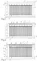
Fig. 1 eine schematische Darstellung eines Brennstoffzellenstapels, der aus einer Mehrzahl von Brennstoffzellen aufgebaut ist, die durch Spannelemente verpresst sind, die zugleich der Sicherung von Steckverbindungen dienen, -
Fig. 2 eine derFigur 1 entsprechende Darstellung mit an den Brennstoffzellen montierten Steckern, die durch einem Spannelement zugeordneten Verbindungselementen mit der Zellspannungsüberwachungseinheit verbunden sind, und -
Fig. 3 eine derFigur 1 entsprechende Darstellung, bei der Stecker und ein Befestigungsteil in ein Spannelement integriert sind. - Eine Brennstoffzellenvorrichtung weist einen Brennstoffzellenstapel 1 mit einer Mehrzahl von in Stapelrichtung angeordneten Brennstoffzellen 2 auf.
- Jede der Brennstoffzellen 2 umfasst eine Anode, eine Kathode sowie eine die Anode von der Kathode trennende, protonenleitfähige Membran. Die Membran ist aus einem Ionomer, vorzugsweise einem sulfonierten Polytetrafluorethylen-Polymer (PTFE) oder einem Polymer der perfluorierten Sulfonsäure (PFSA) gebildet. Alternativ kann die Membran auch als eine sulfonierte Hyd-rocarbon-Membran gebildet sein.
- Über einen Anodenraum kann der Anode Brennstoff, insbesondere Wasserstoff aus einem Brennstofftank zugeführt werden. In einer Polymerelektrolytmembranbrennstoffzelle (PEM-Brennstoffzelle) werden an der Anode Brennstoff oder Brennstoffmoleküle in Protonen und Elektronen aufgespaltet. Die PEM lässt die Protonen hindurch, ist aber undurchlässig für die Elektronen. An der Anode erfolgt beispielsweise die Reaktion: 2H2 -> 4H+ + 4e-(Oxidation/Elektronenabgabe) Während die Protonen durch die PEM zur Kathode hindurchtreten, werden die Elektronen über einen externen Stromkreis an die Kathode oder an einen Energiespeicher geleitet.
- Über einen Kathodenraum kann der Kathode das Kathodengas (zum Beispiel Sauerstoff oder Sauerstoff enthaltende Luft) zugeführt werden, so dass kathodenseitig die folgende Reaktion stattfindet: O2 + 4H+ +4e- -> 2H2O (Reduktion/Elektronenaufnahme) Der Brennstoffzellenstapel 1 verfügt auch über eine durch Spannelemente 3 gebildete Spannvorrichtung für das Zusammendrücken der Brennstoffzellen 2.
- Den endständigen Brennstoffzellen 2 sind dabei Endplatten 4 zugeordnet, an denen für die Krafteinleitung die Spannvorrichtung angeschlossen ist, wobei an einer der Endplatten 4 oder auch an beiden Endplatten 4 die Medienführungen 5 (nur in
Fig. 3 gezeigt) für den Brennstoff, das Oxidationsmittel und ein Kühlmittel angeordnet sind, an den in der Zeichnung dargestellten Ausführungsbeispielen an der linken Endplatte 4. Die Spannelemente 3 sind als starre Zugbänder gebildet, die insbesondere aus Metall gefertigt sein können mit den entsprechenden mechanischen Eigenschaften hinsichtlich der Festigkeit und Biegesteifigkeit. - Der Brennstoffzellenstapel 1 verfügt weiterhin vorzugsweise für jede der Brennstoffzellen 2 über einen Zellspannungsabgriff 6 zur elektrischen Verbindung mit einer Zellüberwachungseinheit 7, um so eine Diagnose der fehlerfreien Funktion zu ermöglichen. Die Zellspannungsabgriffe 6 sind durch mindestens eines der Spannelemente 3 mechanisch hinsichtlich der Verbindung mit den Brennstoffzellen 2 gesichert.
-
Figur 1 zeigt dabei eine Ausführungsform, bei der jeder Zellspannungsabgriff 6 einen Stecker 8 für eine Steckverbindung umfasst, so dass bei dieser Ausführungsform die zusätzliche mechanische Sicherung im Vordergrund steht. Zusätzlich können aber auch die Stecker 8 an dem Spannelement 3 vormontiert sein, um so das Spannelement 3 als Montagehilfe nutzen zu können, wo bei das Spannelement 3 Durchführungen für zur Zellüberwachungseinheit 7 geführte Kabel aufweist. - Die
Figur 2 zeigt eine Ausführungsform, bei der jeder Stecker 8 an einer der Brennstoffzellen 2 angeordnet ist, wobei in dem Spannelement 3 ein Befestigungsteil 9 für die Stecker 8 aufgenommen ist für die elektrischen Verbindungen mit der Zellüberwachungseinheit 7, und zwar indem die Stecker 8 durch Steckbuchsen 10 und das Befestigungsteil 9 durch ein Spritzgussteil 11 gebildet sind, durch das die elektrischen Verbindungen zu einer Leiterplatte 12 geführt sind, die mit der Zellüberwachungseinheit 7 elektrisch und insbesondere mechanisch verbunden ist. -
Figur 3 zeigt eine Ausführungsform, bei der weiterhin die Stecker 6 und das Befestigungsteil 9 integral in einem Bauteil 13 zusammengefasst sind, das in das Spannelement 3 integriert ist. Die Kontaktierung ist an dem Bauteil 13 mit einem Überstand 14 ausgeführt, so dass über die Leiterplatte 12 die Anbindung an die Zellüberwachungseinheit 7 mit Lötkontakten realisiert werden kann. - Brennstoffzellenvorrichtungen mit einem derartigen Brennstoffzellenstapel zeigen ihre Vorteile insbesondere bei der Anwendung in einem Kraftfahrzeug, da dort besondere mechanische Belastungen und Erschütterungen vorliegen.
-
- 1
- Brennstoffzelle
- 2
- Elektrolytmembran
- 3
- erste Seite der Membran
- 4
- Elektrode / Anode
- 5
- zweite Seite der Membran
- 6
- Elektrode / Kathode
- 7
- anodenseitige Gasdiffusionslage
- 8
- kathodenseitige Gasdiffusionslage
- 9
- Bipolarplatte Brennstoffgas
- 10
- Bipolarplatte Kathodengas
- 11
- Brennstoffflussfeld
- 12
- Kathodengasflussfeld
- 13
- Katalysatorpartikel
- 14
- Trägerpartikel
- 15
- Ionomerbinder
- 16
- Katalysatorpaste
- 17
- Auftragungsmittel
- 18
- Kammer
- 19
- Trocknungseinheit
- 20
- Folienbahn
- 21
- Förderrichtung
- 22
- Strömungsrichtung
- 23
- Elektrolytmembran-Zuführvorrichtung
- 24
- Bahnpfad
- 25
- Coil
- 26
- Zuschnitt
- 27
- Rand
Claims (7)
- Brennstoffzellenstapel (1) mit einer Mehrzahl von in Stapelrichtung angeordneten, mittels Spannelementen (3) verspannten Brennstoffzellen (2), von denen mindestens eine, vorzugsweise jede einen Zellspannungsabgriff (6) aufweist zur elektrischen Verbindung mit einer Zellüberwachungseinheit (7), wobei dass der mindestens eine Zellspannungsabgriff (6) durch mindestens eines der Spannelemente (3) mechanisch hinsichtlich der Verbindung mit den Brennstoffzellen (2) gesichert sind, dadurch gekennzeichnet, dass jeder Zellspannungsabgriff (6) einen Stecker (8) für eine Steckverbindung umfasst, und dass die Stecker (8) an dem Spannelement (3) vormontiert sind, oder dass jeder Stecker (8) an einer der Brennstoffzellen (2) angeordnet ist, und dass in dem Spannelement (3) ein Befestigungsteil (9) für die Stecker (8) aufgenommen ist für die elektrischen Verbindungen mit der Zellüberwachungseinheit (7).
- Brennstoffzellenstapel (1) nach Anspruch 1, dadurch gekennzeichnet, dass das Spannelement (3) Durchführungen für zur Zellüberwachungseinheit (7) geführte Kabel aufweist.
- Brennstoffzellenstapel (1) nach Anspruch 1, dadurch gekennzeichnet, dass die Stecker (8) durch Steckbuchsen (10) und das Befestigungsteil (9) durch ein Spritzgussteil (11) gebildet sind, durch das die elektrischen Verbindungen zu einer Leiterplatte (12) geführt sind, die mit der Zellüberwachungseinheit (7) verbunden ist.
- Brennstoffzellenstapel (1) nach Anspruch 1, dadurch gekennzeichnet, dass die Stecker (8) und das Befestigungsteil (9) integral in einem Bauteil (13) zusammengefasst sind.
- Brennstoffzellenstapel (1) nach einem der Ansprüche 1 bis 4, dadurch gekennzeichnet, dass die Brennstoffzellen (2) zwischen Endplatten (4) durch die Spannelement (3) verspannt sind, die als starre Zugbänder gebildet sind.
- Brennstoffzellenvorrichtung mit einem Brennstoffzellenstapel (1) nach einem der Ansprüche 1 bis 5.
- Kraftfahrzeug mit einer Brennstoffzellenvorrichtung nach Anspruch 6.
Applications Claiming Priority (2)
| Application Number | Priority Date | Filing Date | Title |
|---|---|---|---|
| DE102020128312.1A DE102020128312A1 (de) | 2020-10-28 | 2020-10-28 | Brennstoffzellenstapel, Brennstoffzellenvorrichtung sowie Kraftfahrzeug mit einer Brennstoffzellenvorrichtung |
| PCT/EP2021/065206 WO2022089787A1 (de) | 2020-10-28 | 2021-06-08 | Brennstoffzellenstapel, brennstoffzellenvorrichtung sowie kraftfahrzeug mit einer brennstoffzellenvorrichtung |
Publications (2)
| Publication Number | Publication Date |
|---|---|
| EP4176479A1 EP4176479A1 (de) | 2023-05-10 |
| EP4176479B1 true EP4176479B1 (de) | 2025-02-12 |
Family
ID=76355507
Family Applications (1)
| Application Number | Title | Priority Date | Filing Date |
|---|---|---|---|
| EP21731142.2A Active EP4176479B1 (de) | 2020-10-28 | 2021-06-08 | Brennstoffzellenstapel, brennstoffzellenvorrichtung sowie kraftfahrzeug mit einer brennstoffzellenvorrichtung |
Country Status (7)
| Country | Link |
|---|---|
| US (1) | US12451507B2 (de) |
| EP (1) | EP4176479B1 (de) |
| JP (1) | JP7373082B2 (de) |
| KR (1) | KR102875315B1 (de) |
| CN (1) | CN116325250A (de) |
| DE (1) | DE102020128312A1 (de) |
| WO (1) | WO2022089787A1 (de) |
Family Cites Families (15)
| Publication number | Priority date | Publication date | Assignee | Title |
|---|---|---|---|---|
| US6432567B1 (en) | 1999-03-17 | 2002-08-13 | Sulzer Hexis Ag | Fuel cell battery with afterburning at the periphery of a cell stack |
| JP4829421B2 (ja) * | 2001-04-19 | 2011-12-07 | 本田技研工業株式会社 | セル電圧検出端子 |
| US7732079B2 (en) * | 2004-03-17 | 2010-06-08 | Honda Motor Co., Ltd. | Fuel cell stack |
| JP2006107789A (ja) | 2004-09-30 | 2006-04-20 | Toshiba Corp | 燃料電池ユニット、基板ユニット、および動作制御方法 |
| KR100646954B1 (ko) | 2005-10-07 | 2006-11-23 | 삼성에스디아이 주식회사 | 연료전지 스택의 셀 전압 측정장치 및 이를 채용한연료전지 시스템 |
| JP5332201B2 (ja) | 2007-12-28 | 2013-11-06 | トヨタ自動車株式会社 | 燃料電池ユニットおよび燃料電池 |
| GB2486180B (en) * | 2010-12-03 | 2017-09-13 | Intelligent Energy Ltd | Connector system for a fuel cell stack |
| JP5481421B2 (ja) | 2011-03-30 | 2014-04-23 | Jx日鉱日石エネルギー株式会社 | 燃料電池モジュール |
| JP6107425B2 (ja) * | 2012-06-01 | 2017-04-05 | 日産自動車株式会社 | 燃料電池 |
| EP3035430B1 (de) | 2014-12-19 | 2019-09-25 | Hexis AG | Brennstoffzellenmodul |
| DE102017215560A1 (de) | 2017-09-05 | 2019-03-07 | Audi Ag | Spannvorrichtung, Brennstoffzellenstapel und Verfahren zum Herstellen der Spannvorrichtung |
| KR101966553B1 (ko) | 2017-10-24 | 2019-04-05 | 현대자동차주식회사 | 연료전지 전압 모니터링 장치 |
| JP6859934B2 (ja) * | 2017-11-28 | 2021-04-14 | トヨタ自動車株式会社 | 燃料電池セルおよび燃料電池 |
| CN110323463B (zh) | 2019-08-02 | 2024-07-12 | 新源动力股份有限公司 | 一种燃料电池双极板及燃料电池电压巡检插件 |
| JP2021072237A (ja) | 2019-11-01 | 2021-05-06 | トヨタ自動車株式会社 | セル電圧計用の端子ユニット |
-
2020
- 2020-10-28 DE DE102020128312.1A patent/DE102020128312A1/de active Pending
-
2021
- 2021-06-08 EP EP21731142.2A patent/EP4176479B1/de active Active
- 2021-06-08 JP JP2022575914A patent/JP7373082B2/ja active Active
- 2021-06-08 KR KR1020237002776A patent/KR102875315B1/ko active Active
- 2021-06-08 WO PCT/EP2021/065206 patent/WO2022089787A1/de not_active Ceased
- 2021-06-08 US US18/007,257 patent/US12451507B2/en active Active
- 2021-06-08 CN CN202180050090.3A patent/CN116325250A/zh active Pending
Also Published As
| Publication number | Publication date |
|---|---|
| WO2022089787A1 (de) | 2022-05-05 |
| EP4176479A1 (de) | 2023-05-10 |
| JP2023528959A (ja) | 2023-07-06 |
| US20230268542A1 (en) | 2023-08-24 |
| DE102020128312A1 (de) | 2022-04-28 |
| KR20230028495A (ko) | 2023-02-28 |
| JP7373082B2 (ja) | 2023-11-01 |
| KR102875315B1 (ko) | 2025-10-23 |
| US12451507B2 (en) | 2025-10-21 |
| CN116325250A (zh) | 2023-06-23 |
Similar Documents
| Publication | Publication Date | Title |
|---|---|---|
| DE19502391C1 (de) | Membranelektrodeneinheit gebildet durch die Zusammenfassung von flächigen Einzelzellen und deren Verwendung | |
| WO2020193055A1 (de) | Bipolarplatte für einen brennstoffzellenstapel und brennstoffzellenstapel | |
| WO2018138107A1 (de) | Bipolarplatten-dichtungsanordnung sowie brennstoffzellenstapel mit einer solchen | |
| DE102017220595A1 (de) | Kompressionsvorrichtung für einen Brennstoffzellenstapel | |
| DE102017215748A1 (de) | Kompressionsvorrichtung für einen Brennstoffzellenstapel | |
| EP4182986A1 (de) | Brennstoffzellenstapel, brennstoffzellenvorrichtung sowie brennstoffzellen-fahrzeug | |
| EP3736894B1 (de) | Bipolarplatte für brennstoffzellen, brennstoffzellenstapel mit solchen bipolarplatten sowie fahrzeug mit einem solchen brennstoffzellenstapel | |
| DE102020209081A1 (de) | Elektrochemischer Reaktionszellenstapel | |
| EP4176479B1 (de) | Brennstoffzellenstapel, brennstoffzellenvorrichtung sowie kraftfahrzeug mit einer brennstoffzellenvorrichtung | |
| WO2022089788A1 (de) | Bipolarplatte, brennstoffzelle sowie brennstoffzellenstapel | |
| DE102016125355A1 (de) | Separatorplatte, Membran-Elektroden-Einheit und Brennstoffzelle | |
| DE102010054305A1 (de) | Brennstoffzellenstapel mit mehreren Brennstoffzellen | |
| DE102019205069A1 (de) | Bipolarplatte für Brennstoffzellen, Brennstoffzellenstapel mit solchen Bipolarplatten sowie Fahrzeug mit einem solchen Brennstoffzellenstapel | |
| DE102013208839A1 (de) | Polarplatte, Brennstoffzelle mit einer solchen und Verfahren zur Herstellung der Polarplatte | |
| DE102021104810A1 (de) | Brennstoffzellenstapel mit mindestens zwei Zellreihen, Brennstoffzellenvorrichtung sowie Kraftfahrzeug | |
| DE102018210165B4 (de) | Spannsystem für Brennstoffzellenstapel und Brennstoffzellenstapel mit einem solchen | |
| WO2022090143A1 (de) | Bipolarplatte mit einsetzbarer blende und brennstoffzellenstapel | |
| DE102017101515A1 (de) | Brennstoffzellenstapel und Brennstoffzellensystem mit einem solchen | |
| DE102020128584A1 (de) | Verfahren zur Fertigung eines eine Mehrzahl von Brennstoffzellen aufweisenden Brennstoffzellenstapels, Brennstoffzelle sowie Brennstoffzellenstapel | |
| EP4244923B1 (de) | Brennstoffzellenstapel mit komprimierbarer gewebestruktur | |
| DE102017215486B4 (de) | Elektrischer Verbinder sowie Brennstoffzellenstapel mit einem solchen | |
| DE112006002510T5 (de) | Brennstoffzelle | |
| WO2021259568A1 (de) | Bipolarplatte sowie brennstoffzellenstapel | |
| EP0942483A1 (de) | Brennstoffzelle mit eingebautem Spannungswandler | |
| DE102016116117A1 (de) | Vorrichtung zur Kompression einer Brennstoffzellenanordnung, Brennstoffzellenanordnung und Kraftfahrzeug |
Legal Events
| Date | Code | Title | Description |
|---|---|---|---|
| STAA | Information on the status of an ep patent application or granted ep patent |
Free format text: STATUS: UNKNOWN |
|
| STAA | Information on the status of an ep patent application or granted ep patent |
Free format text: STATUS: THE INTERNATIONAL PUBLICATION HAS BEEN MADE |
|
| PUAI | Public reference made under article 153(3) epc to a published international application that has entered the european phase |
Free format text: ORIGINAL CODE: 0009012 |
|
| STAA | Information on the status of an ep patent application or granted ep patent |
Free format text: STATUS: REQUEST FOR EXAMINATION WAS MADE |
|
| 17P | Request for examination filed |
Effective date: 20230201 |
|
| AK | Designated contracting states |
Kind code of ref document: A1 Designated state(s): AL AT BE BG CH CY CZ DE DK EE ES FI FR GB GR HR HU IE IS IT LI LT LU LV MC MK MT NL NO PL PT RO RS SE SI SK SM TR |
|
| P01 | Opt-out of the competence of the unified patent court (upc) registered |
Effective date: 20230529 |
|
| DAV | Request for validation of the european patent (deleted) | ||
| DAX | Request for extension of the european patent (deleted) | ||
| GRAP | Despatch of communication of intention to grant a patent |
Free format text: ORIGINAL CODE: EPIDOSNIGR1 |
|
| STAA | Information on the status of an ep patent application or granted ep patent |
Free format text: STATUS: GRANT OF PATENT IS INTENDED |
|
| INTG | Intention to grant announced |
Effective date: 20241126 |
|
| GRAS | Grant fee paid |
Free format text: ORIGINAL CODE: EPIDOSNIGR3 |
|
| GRAA | (expected) grant |
Free format text: ORIGINAL CODE: 0009210 |
|
| STAA | Information on the status of an ep patent application or granted ep patent |
Free format text: STATUS: THE PATENT HAS BEEN GRANTED |
|
| AK | Designated contracting states |
Kind code of ref document: B1 Designated state(s): AL AT BE BG CH CY CZ DE DK EE ES FI FR GB GR HR HU IE IS IT LI LT LU LV MC MK MT NL NO PL PT RO RS SE SI SK SM TR |
|
| REG | Reference to a national code |
Ref country code: GB Ref legal event code: FG4D Free format text: NOT ENGLISH |
|
| REG | Reference to a national code |
Ref country code: CH Ref legal event code: EP |
|
| REG | Reference to a national code |
Ref country code: DE Ref legal event code: R096 Ref document number: 502021006632 Country of ref document: DE |
|
| REG | Reference to a national code |
Ref country code: IE Ref legal event code: FG4D Free format text: LANGUAGE OF EP DOCUMENT: GERMAN |
|
| REG | Reference to a national code |
Ref country code: NL Ref legal event code: MP Effective date: 20250212 |
|
| PG25 | Lapsed in a contracting state [announced via postgrant information from national office to epo] |
Ref country code: RS Free format text: LAPSE BECAUSE OF FAILURE TO SUBMIT A TRANSLATION OF THE DESCRIPTION OR TO PAY THE FEE WITHIN THE PRESCRIBED TIME-LIMIT Effective date: 20250512 |
|
| PG25 | Lapsed in a contracting state [announced via postgrant information from national office to epo] |
Ref country code: FI Free format text: LAPSE BECAUSE OF FAILURE TO SUBMIT A TRANSLATION OF THE DESCRIPTION OR TO PAY THE FEE WITHIN THE PRESCRIBED TIME-LIMIT Effective date: 20250212 |
|
| PG25 | Lapsed in a contracting state [announced via postgrant information from national office to epo] |
Ref country code: PL Free format text: LAPSE BECAUSE OF FAILURE TO SUBMIT A TRANSLATION OF THE DESCRIPTION OR TO PAY THE FEE WITHIN THE PRESCRIBED TIME-LIMIT Effective date: 20250212 |
|
| PGFP | Annual fee paid to national office [announced via postgrant information from national office to epo] |
Ref country code: DE Payment date: 20250630 Year of fee payment: 5 |
|
| PG25 | Lapsed in a contracting state [announced via postgrant information from national office to epo] |
Ref country code: ES Free format text: LAPSE BECAUSE OF FAILURE TO SUBMIT A TRANSLATION OF THE DESCRIPTION OR TO PAY THE FEE WITHIN THE PRESCRIBED TIME-LIMIT Effective date: 20250212 |
|
| PGFP | Annual fee paid to national office [announced via postgrant information from national office to epo] |
Ref country code: GB Payment date: 20250621 Year of fee payment: 5 |
|
| REG | Reference to a national code |
Ref country code: LT Ref legal event code: MG9D |
|
| PG25 | Lapsed in a contracting state [announced via postgrant information from national office to epo] |
Ref country code: IS Free format text: LAPSE BECAUSE OF FAILURE TO SUBMIT A TRANSLATION OF THE DESCRIPTION OR TO PAY THE FEE WITHIN THE PRESCRIBED TIME-LIMIT Effective date: 20250612 Ref country code: NO Free format text: LAPSE BECAUSE OF FAILURE TO SUBMIT A TRANSLATION OF THE DESCRIPTION OR TO PAY THE FEE WITHIN THE PRESCRIBED TIME-LIMIT Effective date: 20250512 |
|
| PG25 | Lapsed in a contracting state [announced via postgrant information from national office to epo] |
Ref country code: NL Free format text: LAPSE BECAUSE OF FAILURE TO SUBMIT A TRANSLATION OF THE DESCRIPTION OR TO PAY THE FEE WITHIN THE PRESCRIBED TIME-LIMIT Effective date: 20250212 |
|
| PG25 | Lapsed in a contracting state [announced via postgrant information from national office to epo] |
Ref country code: HR Free format text: LAPSE BECAUSE OF FAILURE TO SUBMIT A TRANSLATION OF THE DESCRIPTION OR TO PAY THE FEE WITHIN THE PRESCRIBED TIME-LIMIT Effective date: 20250212 |
|
| PG25 | Lapsed in a contracting state [announced via postgrant information from national office to epo] |
Ref country code: LV Free format text: LAPSE BECAUSE OF FAILURE TO SUBMIT A TRANSLATION OF THE DESCRIPTION OR TO PAY THE FEE WITHIN THE PRESCRIBED TIME-LIMIT Effective date: 20250212 Ref country code: PT Free format text: LAPSE BECAUSE OF FAILURE TO SUBMIT A TRANSLATION OF THE DESCRIPTION OR TO PAY THE FEE WITHIN THE PRESCRIBED TIME-LIMIT Effective date: 20250612 |
|
| PGFP | Annual fee paid to national office [announced via postgrant information from national office to epo] |
Ref country code: FR Payment date: 20250617 Year of fee payment: 5 |
|
| PG25 | Lapsed in a contracting state [announced via postgrant information from national office to epo] |
Ref country code: GR Free format text: LAPSE BECAUSE OF FAILURE TO SUBMIT A TRANSLATION OF THE DESCRIPTION OR TO PAY THE FEE WITHIN THE PRESCRIBED TIME-LIMIT Effective date: 20250513 Ref country code: BG Free format text: LAPSE BECAUSE OF FAILURE TO SUBMIT A TRANSLATION OF THE DESCRIPTION OR TO PAY THE FEE WITHIN THE PRESCRIBED TIME-LIMIT Effective date: 20250212 |
|
| PGFP | Annual fee paid to national office [announced via postgrant information from national office to epo] |
Ref country code: AT Payment date: 20250721 Year of fee payment: 5 |
|
| PG25 | Lapsed in a contracting state [announced via postgrant information from national office to epo] |
Ref country code: SE Free format text: LAPSE BECAUSE OF FAILURE TO SUBMIT A TRANSLATION OF THE DESCRIPTION OR TO PAY THE FEE WITHIN THE PRESCRIBED TIME-LIMIT Effective date: 20250212 |
|
| PG25 | Lapsed in a contracting state [announced via postgrant information from national office to epo] |
Ref country code: SM Free format text: LAPSE BECAUSE OF FAILURE TO SUBMIT A TRANSLATION OF THE DESCRIPTION OR TO PAY THE FEE WITHIN THE PRESCRIBED TIME-LIMIT Effective date: 20250212 |
|
| PG25 | Lapsed in a contracting state [announced via postgrant information from national office to epo] |
Ref country code: DK Free format text: LAPSE BECAUSE OF FAILURE TO SUBMIT A TRANSLATION OF THE DESCRIPTION OR TO PAY THE FEE WITHIN THE PRESCRIBED TIME-LIMIT Effective date: 20250212 |
|
| PG25 | Lapsed in a contracting state [announced via postgrant information from national office to epo] |
Ref country code: IT Free format text: LAPSE BECAUSE OF FAILURE TO SUBMIT A TRANSLATION OF THE DESCRIPTION OR TO PAY THE FEE WITHIN THE PRESCRIBED TIME-LIMIT Effective date: 20250212 |
|
| PG25 | Lapsed in a contracting state [announced via postgrant information from national office to epo] |
Ref country code: EE Free format text: LAPSE BECAUSE OF FAILURE TO SUBMIT A TRANSLATION OF THE DESCRIPTION OR TO PAY THE FEE WITHIN THE PRESCRIBED TIME-LIMIT Effective date: 20250212 Ref country code: CZ Free format text: LAPSE BECAUSE OF FAILURE TO SUBMIT A TRANSLATION OF THE DESCRIPTION OR TO PAY THE FEE WITHIN THE PRESCRIBED TIME-LIMIT Effective date: 20250212 |
|
| PG25 | Lapsed in a contracting state [announced via postgrant information from national office to epo] |
Ref country code: RO Free format text: LAPSE BECAUSE OF FAILURE TO SUBMIT A TRANSLATION OF THE DESCRIPTION OR TO PAY THE FEE WITHIN THE PRESCRIBED TIME-LIMIT Effective date: 20250212 |
|
| PG25 | Lapsed in a contracting state [announced via postgrant information from national office to epo] |
Ref country code: SK Free format text: LAPSE BECAUSE OF FAILURE TO SUBMIT A TRANSLATION OF THE DESCRIPTION OR TO PAY THE FEE WITHIN THE PRESCRIBED TIME-LIMIT Effective date: 20250212 |
|
| REG | Reference to a national code |
Ref country code: DE Ref legal event code: R097 Ref document number: 502021006632 Country of ref document: DE |
|
| PLBE | No opposition filed within time limit |
Free format text: ORIGINAL CODE: 0009261 |
|
| STAA | Information on the status of an ep patent application or granted ep patent |
Free format text: STATUS: NO OPPOSITION FILED WITHIN TIME LIMIT |
|
| REG | Reference to a national code |
Ref country code: CH Ref legal event code: L10 Free format text: ST27 STATUS EVENT CODE: U-0-0-L10-L00 (AS PROVIDED BY THE NATIONAL OFFICE) Effective date: 20251224 |
|
| 26N | No opposition filed |
Effective date: 20251113 |
|
| REG | Reference to a national code |
Ref country code: CH Ref legal event code: H13 Free format text: ST27 STATUS EVENT CODE: U-0-0-H10-H13 (AS PROVIDED BY THE NATIONAL OFFICE) Effective date: 20260127 |
|
| PG25 | Lapsed in a contracting state [announced via postgrant information from national office to epo] |
Ref country code: MC Free format text: LAPSE BECAUSE OF FAILURE TO SUBMIT A TRANSLATION OF THE DESCRIPTION OR TO PAY THE FEE WITHIN THE PRESCRIBED TIME-LIMIT Effective date: 20250212 |
|
| PG25 | Lapsed in a contracting state [announced via postgrant information from national office to epo] |
Ref country code: LU Free format text: LAPSE BECAUSE OF NON-PAYMENT OF DUE FEES Effective date: 20250608 |
|
| REG | Reference to a national code |
Ref country code: BE Ref legal event code: MM Effective date: 20250630 |
|
| PG25 | Lapsed in a contracting state [announced via postgrant information from national office to epo] |
Ref country code: IE Free format text: LAPSE BECAUSE OF NON-PAYMENT OF DUE FEES Effective date: 20250608 |
|
| PG25 | Lapsed in a contracting state [announced via postgrant information from national office to epo] |
Ref country code: BE Free format text: LAPSE BECAUSE OF NON-PAYMENT OF DUE FEES Effective date: 20250630 |