EP4175798B1 - Swing bridge and electrically driven device herewith - Google Patents
Swing bridge and electrically driven device herewith Download PDFInfo
- Publication number
- EP4175798B1 EP4175798B1 EP20942500.8A EP20942500A EP4175798B1 EP 4175798 B1 EP4175798 B1 EP 4175798B1 EP 20942500 A EP20942500 A EP 20942500A EP 4175798 B1 EP4175798 B1 EP 4175798B1
- Authority
- EP
- European Patent Office
- Prior art keywords
- swing bridge
- driven device
- electrically driven
- drive shaft
- oscillating body
- Prior art date
- Legal status (The legal status is an assumption and is not a legal conclusion. Google has not performed a legal analysis and makes no representation as to the accuracy of the status listed.)
- Active
Links
Images



Classifications
-
- B—PERFORMING OPERATIONS; TRANSPORTING
- B26—HAND CUTTING TOOLS; CUTTING; SEVERING
- B26B—HAND-HELD CUTTING TOOLS NOT OTHERWISE PROVIDED FOR
- B26B19/00—Clippers or shavers operating with a plurality of cutting edges, e.g. hair clippers, dry shavers
- B26B19/28—Drive layout for hair clippers or dry shavers, e.g. providing for electromotive drive
-
- B—PERFORMING OPERATIONS; TRANSPORTING
- B26—HAND CUTTING TOOLS; CUTTING; SEVERING
- B26B—HAND-HELD CUTTING TOOLS NOT OTHERWISE PROVIDED FOR
- B26B19/00—Clippers or shavers operating with a plurality of cutting edges, e.g. hair clippers, dry shavers
- B26B19/02—Clippers or shavers operating with a plurality of cutting edges, e.g. hair clippers, dry shavers of the reciprocating-cutter type
-
- B—PERFORMING OPERATIONS; TRANSPORTING
- B26—HAND CUTTING TOOLS; CUTTING; SEVERING
- B26B—HAND-HELD CUTTING TOOLS NOT OTHERWISE PROVIDED FOR
- B26B19/00—Clippers or shavers operating with a plurality of cutting edges, e.g. hair clippers, dry shavers
- B26B19/02—Clippers or shavers operating with a plurality of cutting edges, e.g. hair clippers, dry shavers of the reciprocating-cutter type
- B26B19/04—Cutting heads therefor; Cutters therefor; Securing equipment thereof
- B26B19/046—Cutters being movable in the cutting head
-
- F—MECHANICAL ENGINEERING; LIGHTING; HEATING; WEAPONS; BLASTING
- F16—ENGINEERING ELEMENTS AND UNITS; GENERAL MEASURES FOR PRODUCING AND MAINTAINING EFFECTIVE FUNCTIONING OF MACHINES OR INSTALLATIONS; THERMAL INSULATION IN GENERAL
- F16H—GEARING
- F16H21/00—Gearings comprising primarily only links or levers, with or without slides
- F16H21/10—Gearings comprising primarily only links or levers, with or without slides all movement being in, or parallel to, a single plane
- F16H21/16—Gearings comprising primarily only links or levers, with or without slides all movement being in, or parallel to, a single plane for interconverting rotary motion and reciprocating motion
- F16H21/18—Crank gearings; Eccentric gearings
- F16H21/22—Crank gearings; Eccentric gearings with one connecting-rod and one guided slide to each crank or eccentric
Definitions
- the present invention is concerned with a swing bridge for converting a rotary motion into an oscillating motion, especially into a linear oscillating motion, for an electrically driven device, for example an electric hair removal device, such as a wet or dry shaver.
- the swing bridge may further find application in an electric toothbrush or an electric skin treatment device.
- EP 2 024 147 B1 discloses a swing bridge for converting a rotary motion into an oscillating motion.
- This known swing bridge can be used in an electrically driven device such as a dry shaver.
- the swing bridge comprises an oscillating body with a coupling, a drive shaft and two swing arms.
- the coupling comprises a slot for coupling an eccentrically rotatable drive pin coupled to a drive shaft of an electric motor to the swing bridge.
- the drive shaft of the oscillating body may be coupled to a cutter unit, wherein the two drive shafts, i.e. the drive shaft of the electric motor and the drive shaft of the oscillating body, are arranged in a common plane running through the slot.
- the swing arms can be coupled to a housing of an electrically driven device.
- the oscillating body of the swing bridge is only free to move in a linear direction between the two swing arms.
- the swing bridge therefore, converts a rotary motion of a drive pin into a linear oscillating motion of the drive shaft.
- the alignment of the drive shafts in a common plane may have drawbacks regarding the assembly of an electrically driven device, as the drive shaft of the electric motor has to be arranged in line with the drive shaft of the swing bridge.
- the swing arms of the swing bridge are complicated to form and need plenty of space in a longitudinal direction. Further, an additional coupling comprising a slot is needed in order to couple the swing bridge to an electric motor.
- the swing bridge comprises an oscillating body defining a plane, wherein the oscillating body comprises a slot arranged in the plane, and wherein a first axis extends through the center of the slot perpendicular to the plane.
- the feature of the "swing bridge” may also be named “oscillation bridge” hereinbelow.
- the oscillating body comprises a drive shaft protruding perpendicular to the plane along a second axis, and two webs extending at least substantially perpendicular to the plane.
- the webs or wings have a free end facing away from the oscillating body for securing the oscillating body to permit movement of the oscillating body substantially only parallel to the plane, i.e. in one direction.
- the first axis that extends through the center of the slot perpendicular to the plane and the second axis are offset at least in one direction of the plane, and the second axis is located in a corner section of the oscillating body.
- the plane defined by the oscillating body comprises a greater length in its longitudinal direction, i.e. the swing direction, than in its transverse direction.
- the first axis which extends through the slot perpendicular to the plane, extends through the center of the slot
- the axes are offset at least in said longitudinal direction.
- the second axis is arranged in an edge area of the plane.
- the axes may also be offset in said transverse direction or, preferably, in a combined longitudinal and transverse direction. Independent of the direction of the offset, the offset between the two axes allows to arrange the drive shaft of an electric motor offset to the drive shaft of the oscillating body and thus an offset power transmission.
- the slot may be an elongated hole or a groove.
- the elongated hole or groove has its smaller widening in the longitudinal direction of the swing bridge.
- the swing bridge comprises two webs equally arranged on each side in longitudinal direction of the slot.
- the webs may also refer to the term swing arms, so that the terms swing arm and web may be used synonymously.
- the webs or swing arms are arranged at the lateral ends of the oscillating body in longitudinal direction. Still, there may be embodiments of the invention, wherein it is preferred that the webs are arranged between the slot and the lateral ends in the longitudinal direction of the oscillating body. Further, the webs of the oscillating body each comprise a free end facing away from the oscillating body.
- the width of the webs in the transverse direction is equal to the width of the oscillating body in the transverse direction.
- the width of the webs may also be smaller and/or may also differ or alternate between the oscillating body and their free end.
- the webs comprise preferably a plate-type shape, wherein the free ends of the webs can be used to secure the oscillating body. Therefore, the webs may comprise attachment means at their free ends. Each attachment means may have the form of a protrusion or bead facing away from the oscillating body.
- the width of the webs in the transverse direction is greater than the material strength of the webs in the longitudinal direction.
- the term "material strength” here and on all following pages refers to all features which impact the stiffness of the web, e.g. "material strength” can replaced by the term “material thickness” or other measure to change the stiffness. Consequently, the webs are flexible and thus easily bendable when the oscillating body is moved in its longitudinal direction and the free ends of the webs are secured. However, the webs are stiff when a force acts on the oscillating body in its transverse direction. In addition, it may be preferred, that the webs comprise a different material strength at the end portion to improve the securing. In some embodiments, it may also be preferred, that the oscillating body comprises two webs between the slot and the ending of the oscillating body in the longitudinal direction on one side.
- the opposite side may be arranged within a guiding.
- the guiding may comprise elastic means in order to provide a force according to the force a web provides, when the oscillating body is shifted and the webs are bent. It is even possible, that the oscillating body does not comprise a web at all and comprises a guiding on either side, such an embodiment however, is not part of the claimed invention.
- the slot may be located substantially centrally on the oscillating body. If the swing bridge comprises two webs equally arranged on each side in the longitudinal direction of the slot, a centered arrangement of the slot on the oscillating body ensures an even load acting on the webs, when the webs are secured and the swing bridge oscillates within an electrically driven device. Therefore, a centered location of the slot on the oscillating body can be understood as centered between the webs in the longitudinal direction and preferably also centered between the edges of the oscillating body in the transverse direction.
- the slot may be a cut through the oscillating body, i.e. a through hole, or may be a recess, like a groove.
- the first axis and the second axis may be offset to each other in two directions of the plane.
- the first axis protrudes perpendicular to the plane and through the center of the slot, wherein the second axis is offset in a longitudinal and a transverse direction of the plane.
- the second axis is located in a corner section of the oscillating body.
- the second axis is preferably arranged in the center of the device. Therefore, the offset of the two axes allows to arrange an electric motor offset to the center of the swing bridge and thus, offset to the center of the electrically driven device.
- One embodiment of the swing bridge may comprise the oscillating body with at least two components arranged on top of one another, wherein each of the components comprises a plate-type section, and wherein the plate-type sections are for example connected in an integrally bonded manner, preferably by ultrasonic welding, or by a form fit. If ultrasonic welding connects the components, preferably at least one of the components comprises welding dots, wherein the other component may comprise respective holes. Further, it is preferred, when the upper component comprises the drive shaft and the lower component comprises the at least one web. Consequently, it may be preferred when the upper component comprises a stiffer material and the lower component comprises a more flexible material. Nevertheless, as an alternative, it may be preferred when the two components are formed as one.
- the components of the oscillating body are injection molded.
- the slot may be a cut through or may be recess. Due to the fact that the at least two components are arranged on top of each other, it may be advantageous if the slot only cuts through the lower component, i.e. the component closer to the drive pin. Additionally or as an alternative, it may be advantageous if the slot also forms a cut through and/or a recess within the components arranged on top of the lower component. Furthermore, the shape of the at least two components may differ. Therefore, one component may protrude beyond another component at least in the longitudinal direction on at least one side, preferably in the longitudinal direction. The above-mentioned features also account for an oscillating body with only one component.
- the two webs may be an integral part of one of the at least two components. As mentioned before, it is preferred when the two webs comprise a greater width in the transverse direction than the material strength of the webs in the longitudinal direction.
- the two webs comprise at least partially the same size in transverse direction as the oscillating body and/or the swing bridge.
- the production is considerably simplified if the two webs are an integral part of one the at least two components.
- the two components may comprise a plastic material, wherein the plastic material is preferably a type of polyoxymethylene.
- the upper and lower component should comprise the same type of plastic material, but they may differ in material properties, like strength, hardness, etc. Furthermore, a high mechanical strength as well as a good flowability are required if thin plastic walls such as webs are formed by injection molding. To achieve a high dimensional accuracy it is further advantageous when the material used for injection molding comprises a relatively low shrinkage rate.
- the upper component is formed by POM HOSTAFORM C9021 GV3/30 and the lower component is formed by POM ULTRAFORM H2320 004.
- Other materials, especially materials comprising the required characteristics, may be used as an alternative.
- one of the at least two components and the drive shaft may be form-fitted, wherein the drive shaft is preferably overmolded. It may also be preferred if the drive shaft is screwed or connected to at least one of the two components by other common connecting means. Regardless of the type of connection, it may be preferred, if the connection of the drive shaft comprises ribs, wherein the ribs are supported on the oscillating body. Overmolding of the drive shaft offers the advantage of an inexpensive and a comparatively simple production of the swing bridge. In addition, overmolding allows to connect two materials, i.e. the material of the at least one component and the material of the drive shaft, which may otherwise be difficult to join.
- the drive shaft may comprise a metal material.
- a metallic material has the advantage that the drive shaft wears out less quickly and thus has a higher durability. Since a damage of the drive shaft also causes the function of the swing bridge to fail, a long durability of the drive shaft is desired. This is especially the case, if the drive shaft is non-detachable connected to the swing bridge and therefore, cannot be replaced. It may also be preferred, if the drive shaft is an integral part of at least one of the two components of the oscillating body, wherein the drive shaft may be injection molded together with at least one of the two components, and wherein the drive shaft comprises an additional metal coating.
- the swing bridge may be used within an electrically driven device to convert a rotary motion into an oscillating motion, especially into a linear oscillating motion.
- an electrically driven device may comprise a housing with a chassis, an electric motor mounted in the chassis and comprising an eccentrically rotatable drive pin, and the swing bridge according to one of the before mentioned embodiments.
- the swing bridge is adapted to be mechanically coupled to the drive pin, and the drive pin extends into the slot of the swing bridge.
- the eccentrically rotary motion of the first pin is converted into a linear oscillating motion of the drive shaft by means of the swing bridge.
- the housing may be formed by multiple components, which may be interconnected by common attachment means such as screws, hooks, glue, welding or the like. The same accounts for the chassis.
- the housing or some components of the housing and the chassis may be formed as one.
- the eccentrically rotatable drive pin may be an integral part of the drive shaft but may also be attachable to the drive shaft of the electric motor.
- the eccentrically rotatable drive pin of the electric motor extends into the slot of the swing bridge. Consequently, when the slot comprises an elongated hole with its smaller widening in the longitudinal direction of the swing bridge, a rotation of the drive pin causes an at least substantially linear motion of the swing bridge in its longitudinal direction, when the swing bridge is secured by its webs to the housing and/or chassis.
- the electrically driven device further comprises a button in order to activate the device.
- the electrically driven device may be driven by at least one battery unit, wherein the battery unit is preferably rechargeable, and/or by a power connection to an electric socket.
- the offset of the first axis and the second axis i.e. the offset of the slot and the drive shaft, permit an asymmetric assembly of an electrically driven device, wherein a drive shaft of the electric motor does not need to be in line with the drive shaft of the swing bridge.
- the second axis may form a central axis of the housing and/or the chassis. Therefore, the drive shaft is arranged along the central axis of the housing and/or the chassis. According to the offset between the first and the second axis, the electric motor is consequently offset to the center of the housing and/or the chassis. Preferably, the electric motor is arranged on one side of the housing and/or the chassis. Further, at least one battery unit may be arranged on the opposite side of the housing and/or the chassis.
- the centered arrangement of the drive shaft allows to convert a rotational motion of an electric motor offset to the center of the housing and/or the chassis into a linear oscillating motion around the central axis of the housing and/or the chassis.
- a unit, such as a cutter unit, attached to the drive shaft may also be centrically driven.
- the two webs may be interconnected to the housing and/or the chassis, preferably by hot-staking.
- the two webs may also be interconnected to the housing and/or the chassis by other common connecting means such as by plug or clipped connection, by welding or the like. Due to the interconnection, the free end facing away from the oscillating body is fixed, wherein at least the oscillating body is free to move in its longitudinal direction. During the oscillating movement of the oscillating body, the webs are preferably bending back and forth.
- the swing bridge is preferably secured so that a movement of the swing bridge is only permitted by one degree of freedom, i.e. a linear longitudinal oscillation. If the swing bridge is secured by hot-staking, the free ends of the webs may be pressed into press ribs, whereupon those ribs are melted by hot staking.
- a central axis of the electric motor may be arranged offset to the second axis.
- the drive shaft of the electric motor runs along the central axis of the electric motor. Additionally or alternatively, it may be preferred if the central axis of the electric motor also forms the first axis.
- the electrically driven device may comprise a cap, wherein the cap is removably coupled to the housing, and wherein the put on cap is at least covering a button to actuate the electrically driven device.
- the cap may be removed, while the cap may be attached to the electrically driven device doing storage and/or transportation.
- the use of a cap can prevent an undesired activation of the device and/or an unwanted dirtying, for example an unwanted dirtying of a dopp kit by cut-off hair.
- the cap may protect the electrically driven device against any ingress, for example dust ingress, and, therefore, may extend the durability of the electrically driven device.
- the electrically driven device may further comprise at least one cutter unit, wherein the drive shaft may be mechanically coupled to the at least one cutter unit.
- the at least one cutter unit may comprise at least a slit cutter, wherein the slit cutter comprises at least an outer blade, preferably a foil-type blade, and an inner blade.
- an oscillation of the inner blade is caused by the oscillation of the drive shaft of the oscillating body.
- the electric motor may be sealed against undesirable environmental influences, such as moisture penetration, by at least one of the housing and/or the chassis and/or the cap. This is especially required when the electrically driven device is used within a wet environment such as a bathroom.
- the sealing of the electrically driven device and/or the moisture-sensitive components is effected by common means.
- the swing bridge 1 shown in Figure 1a comprises an oscillating body 2 and a drive shaft 3.
- the oscillating body 2 of Figure 1a has an upper first component 4 and a lower second component 5, wherein the first component 4 comprises a different shape than the second component 5.
- the oscillating body 2 and the respective first and second component 4 and 5 are ultrasonic welded together and define plane X.
- the swing bridge 1 further comprises two webs 6 being an integral part of the second component 5 of the oscillating body 2.
- the two webs 6 each have a free end 7 facing away from the oscillating body 2.
- the webs 6 comprise in general a smaller material strength V compared to their width W.
- the width W of the webs 6 in the transverse direction shown in Figure 1a is a bit smaller than the width of the components 4 and 5 of the oscillating body 2.
- the width W of the webs 6 between the oscillating body 2 and the free end 7 can differ.
- the free ends 7 of Figure 1a have protrusions facing away from the oscillating body 2 for securing the swing bridge 1.
- the second component 5 of the swing bridge 1 has a slot 8 (shown in Figure 2 ) with a first axis I, which runs through the center of the slot 8.
- the drive shaft 3 is overmolded within a corner section of the first component 4 and runs along a second axis II.
- the two axes I and II are offset in two directions of the plane, i.e. a longitudinal and a transverse direction.
- FIG. 1c The section A-A of Figure 1b is shown in Figure 1c .
- Welding dots 9 in Figure 1b are used for ultrasonic welding of the two components 4 and 5 of the oscillating body 2.
- the first component 4 comprising the drive shaft 3 protrudes beyond the second component 5 in the longitudinal direction on the side where the drive shaft 3 is located.
- the overmolding of the drive shaft 3 comprises ribs 10 for support on the first component 4.
- Figure 1c shows a top view of the swing bridge 1. It can be noticed that the first component 4 and the second component 5 are ultrasonic welded by four welding dots 9. Even though it seems that the swing bridge 1 only comprises one web 1 on the left side, the web on the right side is simply covered by the protruding first component 4 as mentioned before. Further, the drive shaft 3, which is located in a corner section of the oscillating body, is offset in two directions of the plane, wherein the offset in the longitudinal direction is bigger than the offset in the transverse direction of plane X.
- FIG. 1d a side view of the swing bridge 1 is shown, wherein the above-mentioned differing width W of the webs 6 can be noticed.
- the width W of web 6 is bigger at the free end 7 comprising the protrusion for securing the swing bridge 1.
- FIG 2 shows an exploded view of the swing bridge 1 of Figures 1a to 1d together with an electric motor 100.
- the second component 5 shows the above-mentioned slot 8.
- the slot 8 depicted in Figure 2 is an elongated hole with a smaller widening in the longitudinal direction of the swing bridge 1.
- the electric motor 100 comprises an eccentrically rotatable drive pin 101. Once the swing bridge 1 and the electric motor 100 are assembled, the drive pin 101 extends into the slot 8 of the swing bridge 1. Thus, a rotatable motion of the drive pin 101 can be converted into an oscillating motion of the swing bridge 1.
- this oscillating motion is a linear oscillating motion in the longitudinal direction of the swing bridge 1 (neglecting the deflection in the direction perpendicular to plane X).
- the drive pin 101 may be coupled to a drive shaft 104 (shown in Figure 4b ) of the electric motor 100 or may be an integral part of the drive shaft 104.
- Figure 2 depicts the offset between a drive shaft 104 of an electric motor 100 and the drive shaft 3 of the swing bridge 1 and, thus, shows an asymmetric assembly.
- a chassis 200 comprising the assembled swing bridge 1 and electric motor 100 together with a battery unit 102 is shown in Figure 3 .
- the chassis 200 is half-open. Hence, the rear wall is at least mostly closed. Additionally or as an alternative, the chassis 200 may be coupled to a housing or may be an integral part of a housing.
- the battery unit 102 is preferably rechargeable.
- the free ends 7 of the swing bridge 1 are secured to the chassis 200.
- One way to secure the swing bridge 1 to the chassis 200 is to press the free ends 7 of the webs 6 into press ribs of the chassis 200 and to melt those ribs by hot-staking. Once the swing bridge 1 is secured, only a movement of the oscillating body 2 is permitted.
- the webs 6 are stiff in their transverse direction, while being flexible in their longitudinal direction.
- a linear oscillating motion of the swing bridge 1 is caused by a rotatable motion of the drive pin 101 extending into the slot 8 of the oscillating body 2.
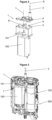
- FIG 4a illustrates an electrically driven device 300 comprising the assembled chassis 200 (not shown) of Figure 3 .
- the electrically driven device 300 here an electric shaver, comprises an upper housing 301, an outer housing 302, a button 303 and a cutter unit 201.
- the upper housing 301 includes the button 303.
- the button 303 is used to actuate the electrically driven device 300.
- FIG. 4b A cross-sectional view of the electrically driven device 300 is shown in Figure 4b .
- the electric driven device 300 comprises the chassis 200 and the cutter unit 201.
- the chassis 200 is fixed within the housing and comprises the swing bridge 1, the electric motor 100 and the battery unit 102.
- the electric motor 1 is arranged on the left side of the electrically driven device 300 and the battery unit 102 is arranged on the right side of the chassis 200 as seen in Figure 4b .
- the assembly of the electric motor 100 and the battery unit 102 is asymmetric according to the drive shaft 3 of the swing bridge 1.
- the electric motor 100 comprises a drive shaft 104 and an attachable eccentrically rotatable drive pin 101.
- the drive pin 101 extends into the slot 8 and mechanically couples the electric motor 100 to the swing bridge 1, wherein the swing bridge 1 is secured within an outer and an interior wall of the chassis 200.
- the drive pin 101 extends through slot 8 of the second component 5 and protrudes into a recess of the first component 4.
- drive shaft 3 of the swing bridge 1 is mechanically coupled to the cutter unit 201.
- the electrically driven device 300 comprises multiple housing parts, i.e. the upper housing 301, the outer housing 302, a lower housing 304 and an inner housing 305. All housing parts 301, 302, 304 and 305 and the chassis 200 are coupled by attachment means such as hooks, screws or the like. Further, the upper housing 301 comprises a softer material than the inner housing 305. In order to prevent the inner component parts of the electrically driven device 300 to be wetted, especially the electric motor 100 and the battery unit 102, the housing parts and/or the chassis are sealed by seals 306.
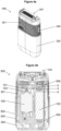
- FIG. 5 shows a cap 307 that can be attached to the electrically driven device 300 during storage and/or transport.
- the dotted lines in Figure 5 demonstrate the way of assembly of some housing components and seals 306 to the chassis 200.
- the assembled exemplary electrically driven device 300 with the electric motor 100, the battery unit 102, the swing bridge 1 and the cutter unit 201 is therefore adapted to convert the rotatable motion of the drive shaft 104 of the electric motor 100 into a linear oscillation of the drive shaft 3 and thus to operate the cutter unit 201. Therefore, the swing bridge 1 converts the rotatable motion of the drive shaft 104 of the electric motor 100 and the respective eccentrically drive pin 101 into a linear oscillating motion of the drive shaft 3 and thus the cutter unit 201.
- the drive shaft 104 starts rotating.
- the drive pin 101 which is attached to the drive shaft 104 converts the rotatable motion into an eccentrically rotatable motion.
- the drive pin 101 continues to rotate, the drive pin 101 reaches the bigger widening of the elongated hole, followed by a push of the swing bridge 1 in the opposite direction, i.e. to the left side. Between the transition of the movement of the swing bridge from the right to the left, the webs 6 relax before they are bent again. As the rotatable motion of the drive pin 101 continues, the swing bridge 1 and therefore the drive shaft 3 continues to oscillate in its longitudinal direction, which operates the cutter unit 201.
- the electric motor 100 can be assembled within the electrically driven device 300 in an edge portion, close to the side walls of the chassis and/or the housing. Hence, space for a battery unit 102 on the side opposite to the electric motor 100 is created and the use of the available installation space can be optimized.
- inventive swing bridge 1 is particularly suitable for small electrically driven devices
Landscapes
- Engineering & Computer Science (AREA)
- Mechanical Engineering (AREA)
- Life Sciences & Earth Sciences (AREA)
- Forests & Forestry (AREA)
- General Engineering & Computer Science (AREA)
- Dry Shavers And Clippers (AREA)
- Brushes (AREA)
Description
- The present invention is concerned with a swing bridge for converting a rotary motion into an oscillating motion, especially into a linear oscillating motion, for an electrically driven device, for example an electric hair removal device, such as a wet or dry shaver. The swing bridge may further find application in an electric toothbrush or an electric skin treatment device.
-
EP 2 024 147 B1 - Prior art document
US-A-5.679.991 discloses the preamble ofclaim 1. - It is an object of the present disclosure to provide a swing bridge and an electrically driven device comprising the swing bridge for converting a rotary motion into an oscillating motion, especially into a linear oscillating motion of a cutter unit, improving the required space within an electrically driven device as well as the way of assembling the swing bridge to an electric motor and a cutter unit.
- This object is solved by a swing bridge for converting a rotary motion into an oscillating motion, especially into a linear oscillating motion as defined in
claim 1 and by an electrically driven device defined inclaim 9. - The swing bridge comprises an oscillating body defining a plane, wherein the oscillating body comprises a slot arranged in the plane, and wherein a first axis extends through the center of the slot perpendicular to the plane. The feature of the "swing bridge" may also be named "oscillation bridge" hereinbelow. Further, the oscillating body comprises a drive shaft protruding perpendicular to the plane along a second axis, and two webs extending at least substantially perpendicular to the plane. The webs or wings have a free end facing away from the oscillating body for securing the oscillating body to permit movement of the oscillating body substantially only parallel to the plane, i.e. in one direction. The first axis that extends through the center of the slot perpendicular to the plane and the second axis are offset at least in one direction of the plane, and the second axis is located in a corner section of the oscillating body.
- Preferably, the plane defined by the oscillating body comprises a greater length in its longitudinal direction, i.e. the swing direction, than in its transverse direction. The first axis, which extends through the slot perpendicular to the plane, extends through the center of the slot Preferably, the axes are offset at least in said longitudinal direction. Further, it is preferred, when the second axis is arranged in an edge area of the plane. The axes may also be offset in said transverse direction or, preferably, in a combined longitudinal and transverse direction. Independent of the direction of the offset, the offset between the two axes allows to arrange the drive shaft of an electric motor offset to the drive shaft of the oscillating body and thus an offset power transmission. The slot may be an elongated hole or a groove. Preferably, the elongated hole or groove has its smaller widening in the longitudinal direction of the swing bridge. Preferably, the swing bridge comprises two webs equally arranged on each side in longitudinal direction of the slot. The webs may also refer to the term swing arms, so that the terms swing arm and web may be used synonymously. Preferably, the webs or swing arms are arranged at the lateral ends of the oscillating body in longitudinal direction. Still, there may be embodiments of the invention, wherein it is preferred that the webs are arranged between the slot and the lateral ends in the longitudinal direction of the oscillating body. Further, the webs of the oscillating body each comprise a free end facing away from the oscillating body. Preferably, the width of the webs in the transverse direction is equal to the width of the oscillating body in the transverse direction. However, the width of the webs may also be smaller and/or may also differ or alternate between the oscillating body and their free end. Moreover, the webs comprise preferably a plate-type shape, wherein the free ends of the webs can be used to secure the oscillating body. Therefore, the webs may comprise attachment means at their free ends. Each attachment means may have the form of a protrusion or bead facing away from the oscillating body. Preferably, the width of the webs in the transverse direction is greater than the material strength of the webs in the longitudinal direction. The term "material strength" here and on all following pages refers to all features which impact the stiffness of the web, e.g. "material strength" can replaced by the term "material thickness" or other measure to change the stiffness. Consequently, the webs are flexible and thus easily bendable when the oscillating body is moved in its longitudinal direction and the free ends of the webs are secured. However, the webs are stiff when a force acts on the oscillating body in its transverse direction. In addition, it may be preferred, that the webs comprise a different material strength at the end portion to improve the securing. In some embodiments, it may also be preferred, that the oscillating body comprises two webs between the slot and the ending of the oscillating body in the longitudinal direction on one side. In the case, wherein only one side comprises two webs, the opposite side may be arranged within a guiding. The guiding may comprise elastic means in order to provide a force according to the force a web provides, when the oscillating body is shifted and the webs are bent. It is even possible, that the oscillating body does not comprise a web at all and comprises a guiding on either side, such an embodiment however, is not part of the claimed invention.
- In one embodiment, the slot may be located substantially centrally on the oscillating body. If the swing bridge comprises two webs equally arranged on each side in the longitudinal direction of the slot, a centered arrangement of the slot on the oscillating body ensures an even load acting on the webs, when the webs are secured and the swing bridge oscillates within an electrically driven device. Therefore, a centered location of the slot on the oscillating body can be understood as centered between the webs in the longitudinal direction and preferably also centered between the edges of the oscillating body in the transverse direction. The slot may be a cut through the oscillating body, i.e. a through hole, or may be a recess, like a groove.
- Further, in one embodiment of the swing bridge, the first axis and the second axis may be offset to each other in two directions of the plane. Preferably, the first axis protrudes perpendicular to the plane and through the center of the slot, wherein the second axis is offset in a longitudinal and a transverse direction of the plane. The second axis is located in a corner section of the oscillating body. When the swing bridge is used within an electrically driven device, the second axis is preferably arranged in the center of the device. Therefore, the offset of the two axes allows to arrange an electric motor offset to the center of the swing bridge and thus, offset to the center of the electrically driven device.
- One embodiment of the swing bridge may comprise the oscillating body with at least two components arranged on top of one another, wherein each of the components comprises a plate-type section, and wherein the plate-type sections are for example connected in an integrally bonded manner, preferably by ultrasonic welding, or by a form fit. If ultrasonic welding connects the components, preferably at least one of the components comprises welding dots, wherein the other component may comprise respective holes. Further, it is preferred, when the upper component comprises the drive shaft and the lower component comprises the at least one web. Consequently, it may be preferred when the upper component comprises a stiffer material and the lower component comprises a more flexible material. Nevertheless, as an alternative, it may be preferred when the two components are formed as one. Regardless of the number of components, preferably the components of the oscillating body are injection molded. As mentioned before, the slot may be a cut through or may be recess. Due to the fact that the at least two components are arranged on top of each other, it may be advantageous if the slot only cuts through the lower component, i.e. the component closer to the drive pin. Additionally or as an alternative, it may be advantageous if the slot also forms a cut through and/or a recess within the components arranged on top of the lower component. Furthermore, the shape of the at least two components may differ. Therefore, one component may protrude beyond another component at least in the longitudinal direction on at least one side, preferably in the longitudinal direction. The above-mentioned features also account for an oscillating body with only one component.
- In addition, the two webs may be an integral part of one of the at least two components. As mentioned before, it is preferred when the two webs comprise a greater width in the transverse direction than the material strength of the webs in the longitudinal direction.
- Preferably, the two webs comprise at least partially the same size in transverse direction as the oscillating body and/or the swing bridge. The production is considerably simplified if the two webs are an integral part of one the at least two components. However, it may also be preferred when the webs of the oscillating body are connected to the oscillating body by common connecting means and methods.
- In one embodiment, the two components may comprise a plastic material, wherein the plastic material is preferably a type of polyoxymethylene. For the use of ultrasonic welding, the upper and lower component should comprise the same type of plastic material, but they may differ in material properties, like strength, hardness, etc. Furthermore, a high mechanical strength as well as a good flowability are required if thin plastic walls such as webs are formed by injection molding. To achieve a high dimensional accuracy it is further advantageous when the material used for injection molding comprises a relatively low shrinkage rate. Thus, according to one example, the upper component is formed by POM HOSTAFORM C9021 GV3/30 and the lower component is formed by POM ULTRAFORM H2320 004. Other materials, especially materials comprising the required characteristics, may be used as an alternative.
- In an additional or an alternative embodiment, one of the at least two components and the drive shaft may be form-fitted, wherein the drive shaft is preferably overmolded. It may also be preferred if the drive shaft is screwed or connected to at least one of the two components by other common connecting means. Regardless of the type of connection, it may be preferred, if the connection of the drive shaft comprises ribs, wherein the ribs are supported on the oscillating body. Overmolding of the drive shaft offers the advantage of an inexpensive and a comparatively simple production of the swing bridge. In addition, overmolding allows to connect two materials, i.e. the material of the at least one component and the material of the drive shaft, which may otherwise be difficult to join.
- In one embodiment, the drive shaft may comprise a metal material. The use of a metallic material has the advantage that the drive shaft wears out less quickly and thus has a higher durability. Since a damage of the drive shaft also causes the function of the swing bridge to fail, a long durability of the drive shaft is desired. This is especially the case, if the drive shaft is non-detachable connected to the swing bridge and therefore, cannot be replaced. It may also be preferred, if the drive shaft is an integral part of at least one of the two components of the oscillating body, wherein the drive shaft may be injection molded together with at least one of the two components, and wherein the drive shaft comprises an additional metal coating.
- Both, the choice of material for each individual component of the swing bridge as well as the method of manufacture, should be chosen in accordance with the use of the swing bridge and in particular in accordance with the loads acting its individual components.
- The swing bridge may be used within an electrically driven device to convert a rotary motion into an oscillating motion, especially into a linear oscillating motion. According to
claim 9, such an electrically driven device may comprise a housing with a chassis, an electric motor mounted in the chassis and comprising an eccentrically rotatable drive pin, and the swing bridge according to one of the before mentioned embodiments. The swing bridge is adapted to be mechanically coupled to the drive pin, and the drive pin extends into the slot of the swing bridge. Thus, the eccentrically rotary motion of the first pin is converted into a linear oscillating motion of the drive shaft by means of the swing bridge. - The housing may be formed by multiple components, which may be interconnected by common attachment means such as screws, hooks, glue, welding or the like. The same accounts for the chassis. In addition, the housing or some components of the housing and the chassis may be formed as one. The eccentrically rotatable drive pin may be an integral part of the drive shaft but may also be attachable to the drive shaft of the electric motor. Preferably, the eccentrically rotatable drive pin of the electric motor extends into the slot of the swing bridge. Consequently, when the slot comprises an elongated hole with its smaller widening in the longitudinal direction of the swing bridge, a rotation of the drive pin causes an at least substantially linear motion of the swing bridge in its longitudinal direction, when the swing bridge is secured by its webs to the housing and/or chassis. The conversion of a rotatable motion into a linear motion allows to use rotatable electric motors that are well-known, inexpensive and that comprise a high durability. Preferably, the electrically driven device further comprises a button in order to activate the device. The electrically driven device may be driven by at least one battery unit, wherein the battery unit is preferably rechargeable, and/or by a power connection to an electric socket. Additionally, the offset of the first axis and the second axis, i.e. the offset of the slot and the drive shaft, permit an asymmetric assembly of an electrically driven device, wherein a drive shaft of the electric motor does not need to be in line with the drive shaft of the swing bridge.
- In one embodiment, the second axis may form a central axis of the housing and/or the chassis. Therefore, the drive shaft is arranged along the central axis of the housing and/or the chassis. According to the offset between the first and the second axis, the electric motor is consequently offset to the center of the housing and/or the chassis. Preferably, the electric motor is arranged on one side of the housing and/or the chassis. Further, at least one battery unit may be arranged on the opposite side of the housing and/or the chassis. The centered arrangement of the drive shaft allows to convert a rotational motion of an electric motor offset to the center of the housing and/or the chassis into a linear oscillating motion around the central axis of the housing and/or the chassis. Hence, a unit, such as a cutter unit, attached to the drive shaft may also be centrically driven.
- Preferably, the two webs may be interconnected to the housing and/or the chassis, preferably by hot-staking. The two webs may also be interconnected to the housing and/or the chassis by other common connecting means such as by plug or clipped connection, by welding or the like. Due to the interconnection, the free end facing away from the oscillating body is fixed, wherein at least the oscillating body is free to move in its longitudinal direction. During the oscillating movement of the oscillating body, the webs are preferably bending back and forth. By interconnecting the at least one web to the housing and/or the chassis, the swing bridge is preferably secured so that a movement of the swing bridge is only permitted by one degree of freedom, i.e. a linear longitudinal oscillation. If the swing bridge is secured by hot-staking, the free ends of the webs may be pressed into press ribs, whereupon those ribs are melted by hot staking.
- Further, a central axis of the electric motor may be arranged offset to the second axis. Preferably, the drive shaft of the electric motor runs along the central axis of the electric motor. Additionally or alternatively, it may be preferred if the central axis of the electric motor also forms the first axis.
- In one embodiment, the electrically driven device may comprise a cap, wherein the cap is removably coupled to the housing, and wherein the put on cap is at least covering a button to actuate the electrically driven device. During the use of the electrically driven device the cap may be removed, while the cap may be attached to the electrically driven device doing storage and/or transportation. Thus, during storage and/or transportation the use of a cap can prevent an undesired activation of the device and/or an unwanted dirtying, for example an unwanted dirtying of a dopp kit by cut-off hair. Further, the cap may protect the electrically driven device against any ingress, for example dust ingress, and, therefore, may extend the durability of the electrically driven device.
- The electrically driven device may further comprise at least one cutter unit, wherein the drive shaft may be mechanically coupled to the at least one cutter unit. The at least one cutter unit may comprise at least a slit cutter, wherein the slit cutter comprises at least an outer blade, preferably a foil-type blade, and an inner blade. Preferably, an oscillation of the inner blade is caused by the oscillation of the drive shaft of the oscillating body.
- Furthermore, the electric motor may be sealed against undesirable environmental influences, such as moisture penetration, by at least one of the housing and/or the chassis and/or the cap. This is especially required when the electrically driven device is used within a wet environment such as a bathroom. The sealing of the electrically driven device and/or the moisture-sensitive components is effected by common means.
- The invention will subsequently be explained in detail with reference to specific embodiments shown in the Figures. All features described and/or shown in the Figures are subject matter of the invention, irrespective of the grouping of the features in the claims and/or their back references.
-
- Figure 1a
- shows a perspective view of a swing bridge according to an embodiment of the invention;
- Figure 1b
- shows a sectional view of the swing bridge of
Figure 1a along line A-A inFigure 1c ; - Figure 1c
- shows a top view of the swing bridge of
Figure 1a ; - Figure 1d
- shows a side view of the swing bridge of
Figure 1a ; - Figure 2
- shows an exploded view of the components of the swing bridge of
Figure 1a together with an electric motor; - Figure 3
- shows a perspective view of the swing bridge and the electric motor of
Figure 2 arranged within a chassis; - Figure 4a
- shows a perspective view of an assembled electrically driven device;
- Figure 4b
- shows a sectional view of the electrically driven device of
Figure 4a ; and - Figure 5
- shows an exploded view of the electrically driven device of
Figure 4a together with a cap. - The
swing bridge 1 shown inFigure 1a comprises anoscillating body 2 and adrive shaft 3. Theoscillating body 2 ofFigure 1a has an upperfirst component 4 and a lowersecond component 5, wherein thefirst component 4 comprises a different shape than thesecond component 5. Theoscillating body 2 and the respective first andsecond component - The
swing bridge 1 further comprises twowebs 6 being an integral part of thesecond component 5 of theoscillating body 2. The twowebs 6 each have afree end 7 facing away from theoscillating body 2. To be bendable in a longitudinal direction, thewebs 6 comprise in general a smaller material strength V compared to their width W. The width W of thewebs 6 in the transverse direction shown inFigure 1a is a bit smaller than the width of thecomponents oscillating body 2. Additionally, the width W of thewebs 6 between theoscillating body 2 and thefree end 7 can differ. Further, the free ends 7 ofFigure 1a have protrusions facing away from theoscillating body 2 for securing theswing bridge 1. - Furthermore, the
second component 5 of theswing bridge 1 has a slot 8 (shown inFigure 2 ) with a first axis I, which runs through the center of theslot 8. Thedrive shaft 3 is overmolded within a corner section of thefirst component 4 and runs along a second axis II. The two axes I and II are offset in two directions of the plane, i.e. a longitudinal and a transverse direction. - The section A-A of
Figure 1b is shown inFigure 1c .Welding dots 9 inFigure 1b are used for ultrasonic welding of the twocomponents oscillating body 2. Thefirst component 4 comprising thedrive shaft 3 protrudes beyond thesecond component 5 in the longitudinal direction on the side where thedrive shaft 3 is located. Moreover, the overmolding of thedrive shaft 3 comprisesribs 10 for support on thefirst component 4. -
Figure 1c shows a top view of theswing bridge 1. It can be noticed that thefirst component 4 and thesecond component 5 are ultrasonic welded by fourwelding dots 9. Even though it seems that theswing bridge 1 only comprises oneweb 1 on the left side, the web on the right side is simply covered by the protrudingfirst component 4 as mentioned before. Further, thedrive shaft 3, which is located in a corner section of the oscillating body, is offset in two directions of the plane, wherein the offset in the longitudinal direction is bigger than the offset in the transverse direction of plane X. - In
Figure 1d a side view of theswing bridge 1 is shown, wherein the above-mentioned differing width W of thewebs 6 can be noticed. The width W ofweb 6 is bigger at thefree end 7 comprising the protrusion for securing theswing bridge 1. -
Figure 2 shows an exploded view of theswing bridge 1 ofFigures 1a to 1d together with anelectric motor 100. Thesecond component 5 shows the above-mentionedslot 8. Theslot 8 depicted inFigure 2 is an elongated hole with a smaller widening in the longitudinal direction of theswing bridge 1. Theelectric motor 100 comprises an eccentricallyrotatable drive pin 101. Once theswing bridge 1 and theelectric motor 100 are assembled, thedrive pin 101 extends into theslot 8 of theswing bridge 1. Thus, a rotatable motion of thedrive pin 101 can be converted into an oscillating motion of theswing bridge 1. Especially when theswing bridge 1 is secured by the free ends 7 of thewebs 6, this oscillating motion is a linear oscillating motion in the longitudinal direction of the swing bridge 1 (neglecting the deflection in the direction perpendicular to plane X). Thedrive pin 101 may be coupled to a drive shaft 104 (shown inFigure 4b ) of theelectric motor 100 or may be an integral part of the drive shaft 104. Further,Figure 2 depicts the offset between a drive shaft 104 of anelectric motor 100 and thedrive shaft 3 of theswing bridge 1 and, thus, shows an asymmetric assembly. - A
chassis 200 comprising the assembledswing bridge 1 andelectric motor 100 together with abattery unit 102 is shown inFigure 3 . Thechassis 200 is half-open. Hence, the rear wall is at least mostly closed. Additionally or as an alternative, thechassis 200 may be coupled to a housing or may be an integral part of a housing. Thebattery unit 102 is preferably rechargeable. Further, the free ends 7 of theswing bridge 1 are secured to thechassis 200. One way to secure theswing bridge 1 to thechassis 200 is to press the free ends 7 of thewebs 6 into press ribs of thechassis 200 and to melt those ribs by hot-staking. Once theswing bridge 1 is secured, only a movement of theoscillating body 2 is permitted. Further, due to the big width W of thewebs 6 compared to their material strength V, thewebs 6 are stiff in their transverse direction, while being flexible in their longitudinal direction. Thus, a linear oscillating motion of theswing bridge 1 is caused by a rotatable motion of thedrive pin 101 extending into theslot 8 of theoscillating body 2. -
Figure 4a illustrates an electrically drivendevice 300 comprising the assembled chassis 200 (not shown) ofFigure 3 . The electrically drivendevice 300, here an electric shaver, comprises anupper housing 301, anouter housing 302, abutton 303 and acutter unit 201. Theupper housing 301 includes thebutton 303. Thebutton 303 is used to actuate the electrically drivendevice 300. - A cross-sectional view of the electrically driven
device 300 is shown inFigure 4b . The electric drivendevice 300 comprises thechassis 200 and thecutter unit 201. Thechassis 200 is fixed within the housing and comprises theswing bridge 1, theelectric motor 100 and thebattery unit 102. Theelectric motor 1 is arranged on the left side of the electrically drivendevice 300 and thebattery unit 102 is arranged on the right side of thechassis 200 as seen inFigure 4b . Hence, the assembly of theelectric motor 100 and thebattery unit 102 is asymmetric according to thedrive shaft 3 of theswing bridge 1. - The
electric motor 100 comprises a drive shaft 104 and an attachable eccentricallyrotatable drive pin 101. Thedrive pin 101 extends into theslot 8 and mechanically couples theelectric motor 100 to theswing bridge 1, wherein theswing bridge 1 is secured within an outer and an interior wall of thechassis 200. As can be seen fromFigure 4b , thedrive pin 101 extends throughslot 8 of thesecond component 5 and protrudes into a recess of thefirst component 4. Further, driveshaft 3 of theswing bridge 1 is mechanically coupled to thecutter unit 201. - Additionally, the electrically driven
device 300 comprises multiple housing parts, i.e. theupper housing 301, theouter housing 302, alower housing 304 and aninner housing 305. Allhousing parts chassis 200 are coupled by attachment means such as hooks, screws or the like. Further, theupper housing 301 comprises a softer material than theinner housing 305. In order to prevent the inner component parts of the electrically drivendevice 300 to be wetted, especially theelectric motor 100 and thebattery unit 102, the housing parts and/or the chassis are sealed byseals 306. -
Additional seals 306 can be seen in an exploded view of the electrically drivendevice 300 inFigure 5 . Furthermore,Figure 5 shows acap 307 that can be attached to the electrically drivendevice 300 during storage and/or transport. The dotted lines inFigure 5 demonstrate the way of assembly of some housing components and seals 306 to thechassis 200. - The assembled exemplary electrically driven
device 300 with theelectric motor 100, thebattery unit 102, theswing bridge 1 and thecutter unit 201 is therefore adapted to convert the rotatable motion of the drive shaft 104 of theelectric motor 100 into a linear oscillation of thedrive shaft 3 and thus to operate thecutter unit 201. Therefore, theswing bridge 1 converts the rotatable motion of the drive shaft 104 of theelectric motor 100 and the respectiveeccentrically drive pin 101 into a linear oscillating motion of thedrive shaft 3 and thus thecutter unit 201. - When the electrically driven
device 300, i.e. theelectric motor 100, is actuated bybutton 303 and thebattery unit 102 powers theelectric motor 100, the drive shaft 104 starts rotating. Thedrive pin 101, which is attached to the drive shaft 104 converts the rotatable motion into an eccentrically rotatable motion. As thedrive pin 101 extends intoslot 8, i.e. an elongated hole with its smaller widening in the longitudinal direction of theswing bridge 1, a full rotation of thedrive pin 101 may first push theswing bridge 1 in the longitudinal direction to its right side, wherein thewebs 6 bent and only theoscillating body 2 of theswing bridge 1 is shifted. Since, thedrive pin 101 continues to rotate, thedrive pin 101 reaches the bigger widening of the elongated hole, followed by a push of theswing bridge 1 in the opposite direction, i.e. to the left side. Between the transition of the movement of the swing bridge from the right to the left, thewebs 6 relax before they are bent again. As the rotatable motion of thedrive pin 101 continues, theswing bridge 1 and therefore thedrive shaft 3 continues to oscillate in its longitudinal direction, which operates thecutter unit 201. - As the
swing bridge 1 enables an offset between thedrive shafts 3 and 104, theelectric motor 100 can be assembled within the electrically drivendevice 300 in an edge portion, close to the side walls of the chassis and/or the housing. Hence, space for abattery unit 102 on the side opposite to theelectric motor 100 is created and the use of the available installation space can be optimized. - Consequently, the use of the
inventive swing bridge 1 is particularly suitable for small electrically driven devices - The scope of protection of the current invention is defined by the appended claims.
-
- 1
- swing bridge
- 2
- oscillating body
- 3
- drive shaft (swing bridge)
- 4
- first component
- 5
- second component
- 6
- web
- 7
- free end
- 8
- slot
- 9
- welding dots
- 10
- ribs
- 100
- electric motor
- 101
- drive pin
- 102
- battery unit
- 104
- drive shaft (electric motor)
- 200
- chassis
- 201
- cutter unit
- 300
- electrically driven device
- 301
- upper housing
- 302
- outer housing
- 303
- button
- 304
- lower housing
- 305
- inner housing
- 306
- seal
- 307
- cap
- 308
- seal /o-rings
- I
- first axis
- II
- second axis
- V
- material strength (web)
- W
- width (web)
- X
- plane
Claims (15)
- A swing bridge for converting a rotary motion into an oscillating motion, especially into a linear oscillating motion, comprising
an oscillating body (2) defining a plane (X), the oscillating body (2) comprising a slot (8) arranged in the plane (X), wherein a first axis (I) extends through the center of the slot (8) perpendicular to the plane (X), and a drive shaft (3) protruding perpendicular to the plane (X) along a second axis (II), two webs (6) extending at least substantially perpendicular to the plane (X), each web (6) having a free end (7) facing away from the oscillating body (2) for securing the oscillating body (2) to permit movement of the oscillating body (2) substantially only parallel to the plane (X), and wherein the first axis (I) and the second axis (II) are offset at least in one direction of the plane (X) characterized in that the second axis (II) is located in a corner section of the oscillating body (2). - The swing bridge according to claim 1, characterized in that the slot (8) is located substantially centrally on the oscillating body (2).
- The swing bridge according to claim 1, characterized in that the first axis (I) and the second axis (II) are offset to each other in two directions of the plane (X).
- The swing bridge according to claims 1 or 2, characterized in that the oscillating body (2) comprises at least two components (4, 5) arranged on top of one another, wherein each of the components comprises a plate-type section, and wherein the plate-type sections are connected in an integrally bonded manner, preferably by ultrasonic welding.
- The swing bridge according to claim 4, characterized in that each web (6) is an integral part of one of the at least two components (4, 5).
- The swing bridge according to any of claims 4 or 5, characterized in that the two components (4, 5) comprise a plastic material, and wherein the plastic material is preferably a type of polyoxymethylene.
- The swing bridge according to any of claims 4 to 6, characterized in that one of the at least two components (4; 5) and the drive shaft (3) are form-fitted, and wherein the drive shaft (3) is preferably overmolded.
- The swing bridge according to any of the preceding claims, characterized in that the drive shaft (3) comprises a metal material.
- An electrically driven device comprisinga housing (301, 302, 304, 305) with a chassis (200),an electric motor (100) mounted in the chassis (200) and comprising an eccentrically rotatable drive pin (101), andthe swing bridge (1) according to any of the preceding claims adapted to be mechanically coupled to the drive pin (101), wherein the drive pin (101) extends into the slot (8) of the swing bridge (1),characterized in thatthe eccentrically rotary motion of the drive pin (101) is converted into a linear oscillating motion of the drive shaft (3) by means of the swing bridge (1).
- The electrically driven device according to claim 9, characterized in that the second axis (II) forms a central axis of the housing (301, 302, 304, 305) and/or the chassis (200).
- The electrically driven device according to any of claims 9 to 10, characterized in that each
web (6) is interconnected to the housing (301, 302, 304, 305) and/or the chassis (200), preferably by hot-staking or ribs at the housing or chassis form-fitting with an end portion of the wings. - The electrically driven device according to any of claims 9 to 11, characterized in that a central axis of the electric motor (100) is arranged offset to the second axis (II).
- The electrically driven device according to any of claims 9 to 12, characterized in that the electrically driven device (300) further comprises a cap (307), wherein the cap (307) is removably coupled to the housing (301, 302, 304, 305), and wherein the put on cap (307) is at least covering a button (303) to actuate the electrically driven device (300).
- The electrically driven device according to any of claims 9 to 13, characterized in that the drive shaft (3) is mechanically coupled to at least one cutter unit (201).
- The electric driven device according to any of claims 9 to 14, characterized in that the electric motor (100) is sealed against undesirable environmental influences, such as moisture penetration, by seals (306, 308) of at least one of the housing (301, 302, 304, 305) and/or the chassis (200) and/or the cap (307).
Applications Claiming Priority (1)
| Application Number | Priority Date | Filing Date | Title |
|---|---|---|---|
| PCT/CN2020/099803 WO2022000390A1 (en) | 2020-07-01 | 2020-07-01 | Swing bridge and electrically driven device herewith |
Publications (2)
| Publication Number | Publication Date |
|---|---|
| EP4175798A1 EP4175798A1 (en) | 2023-05-10 |
| EP4175798B1 true EP4175798B1 (en) | 2025-03-19 |
Family
ID=79317779
Family Applications (1)
| Application Number | Title | Priority Date | Filing Date |
|---|---|---|---|
| EP20942500.8A Active EP4175798B1 (en) | 2020-07-01 | 2020-07-01 | Swing bridge and electrically driven device herewith |
Country Status (5)
| Country | Link |
|---|---|
| US (1) | US12083691B2 (en) |
| EP (1) | EP4175798B1 (en) |
| JP (1) | JP7801301B2 (en) |
| CN (1) | CN115803161A (en) |
| WO (1) | WO2022000390A1 (en) |
Families Citing this family (5)
| Publication number | Priority date | Publication date | Assignee | Title |
|---|---|---|---|---|
| EP4175797A1 (en) * | 2020-07-01 | 2023-05-10 | Braun GmbH | Electrically driven device |
| USD1055384S1 (en) * | 2023-04-18 | 2024-12-24 | Manscaped Llc | Travel shaver |
| USD1097322S1 (en) * | 2023-08-16 | 2025-10-07 | Wahl Clipper Corporation | Shaver with grip sleeve |
| USD1102031S1 (en) * | 2023-08-17 | 2025-11-11 | Zhoushan Dinghai Kerui Electrical Appliance Co., Ltd | Reciprocating shaver |
| USD1097323S1 (en) * | 2023-08-21 | 2025-10-07 | Wahl Clipper Corporation | Shaver with sleeve |
Family Cites Families (54)
| Publication number | Priority date | Publication date | Assignee | Title |
|---|---|---|---|---|
| US3538604A (en) * | 1968-11-27 | 1970-11-10 | Schick Electric Inc | Self-storing shaver |
| US3714711A (en) * | 1970-12-30 | 1973-02-06 | Sperry Rand Corp | Cutter drive member means for electric dry shaver |
| JPS5456565A (en) | 1977-10-11 | 1979-05-07 | Matsushita Electric Works Ltd | Powder switching apparatus for elecrtic razor |
| JPS5823333Y2 (en) * | 1978-09-05 | 1983-05-18 | 三洋電機株式会社 | vibrating electric razor |
| JPS6012516Y2 (en) * | 1980-09-12 | 1985-04-23 | 三洋電機株式会社 | vibrating electric razor |
| US4428117A (en) | 1981-06-30 | 1984-01-31 | Matsushita Electric Works, Ltd. | Reciprocating type electric shaver |
| DE3346655C1 (en) * | 1983-12-23 | 1985-01-24 | Braun Ag, 6000 Frankfurt | Device for converting the rotary movement of an eccentric into a reciprocating movement |
| DE3346656C1 (en) | 1983-12-23 | 1988-12-22 | Braun Ag, 6000 Frankfurt | Device for converting the rotary movement of an eccentric into a reciprocating movement |
| DE8404174U1 (en) * | 1984-02-11 | 1984-05-10 | Braun Ag, 6000 Frankfurt | SWINGARM BRIDGE |
| JPS61220687A (en) | 1985-03-26 | 1986-09-30 | 松下電工株式会社 | Charging type electric razor |
| JPH0323170Y2 (en) | 1985-09-18 | 1991-05-21 | ||
| JPH0431036Y2 (en) * | 1986-02-12 | 1992-07-27 | ||
| AT390393B (en) * | 1986-02-17 | 1990-04-25 | Payer Lux Elektroprod | Electric shaver |
| JPS62201180A (en) * | 1986-02-28 | 1987-09-04 | 東芝テック株式会社 | reciprocating electric razor |
| US5050300A (en) * | 1986-09-17 | 1991-09-24 | Remington Products, Inc. | Electric dry shaver having an improved sealing arrangement |
| DE3912090C1 (en) * | 1989-04-13 | 1990-08-30 | Braun Ag, 6000 Frankfurt, De | Slide switch for electric razor - has cross pieces holding movable guide flanges and exposable for cleaning |
| US5193275A (en) * | 1990-08-28 | 1993-03-16 | Matsushita Electric Works, Ltd. | Flat-shaped dry shaver |
| AT395125B (en) | 1991-01-18 | 1992-09-25 | Philips Nv | ELECTRIC DRY SHAVER |
| JPH0615872A (en) | 1992-07-01 | 1994-01-25 | Ricoh Co Ltd | Image forming device |
| DE4341392C1 (en) * | 1993-12-04 | 1994-12-22 | Braun Ag | Eccentric rocking-link drive |
| JP2838027B2 (en) * | 1993-12-28 | 1998-12-16 | 株式会社テック | Electric shaver |
| US5678312A (en) * | 1994-10-31 | 1997-10-21 | Sanyo Electric Co., Ltd. | Electric shaver with reduced vibration |
| TW353631B (en) | 1995-09-29 | 1999-03-01 | Sanyo Electric Co | Electric razor |
| US5771880A (en) | 1995-11-06 | 1998-06-30 | Tsai; Chin-Lin | Multipurpose gas burner |
| JPH1015259A (en) | 1996-07-03 | 1998-01-20 | Kyushu Hitachi Maxell Ltd | Electric razor |
| JPH10156067A (en) * | 1996-11-26 | 1998-06-16 | Sanyo Electric Co Ltd | Reciprocation type electric razor |
| JPH10211370A (en) | 1997-01-31 | 1998-08-11 | Sanyo Electric Co Ltd | Electric shaver with trimer |
| JP2001009176A (en) | 1999-06-25 | 2001-01-16 | Matsushita Electric Works Ltd | Reciprocating electric razor |
| JP4348836B2 (en) | 1999-11-25 | 2009-10-21 | パナソニック電工株式会社 | Electric razor |
| HK1042669B (en) * | 1999-11-25 | 2003-10-31 | 松下电工株式会社 | Dry shaver with a height adjustable cutter head |
| TWM245035U (en) | 2000-02-23 | 2004-10-01 | Sanyo Electric Co | Electric shaver |
| DE60115989T2 (en) * | 2000-06-07 | 2006-09-21 | Matsushita Electric Works, Ltd., Kadoma | Linear vibration device |
| CN1525720A (en) | 2003-02-28 | 2004-09-01 | 陈建昆 | Multipurpose wireless mobile communication device |
| US20050172492A1 (en) | 2004-02-06 | 2005-08-11 | Ridgewood Industries Llc | Electric shaver |
| DE102006010323A1 (en) * | 2006-03-07 | 2007-09-13 | Braun Gmbh | Dry shaver with swiveling shaving head |
| DE102006022909A1 (en) * | 2006-05-15 | 2007-11-22 | Braun Gmbh | Rocker bridge for converting a rotary motion into an oscillatory motion and use of such in an electrical device |
| KR20080005826U (en) * | 2007-05-28 | 2008-12-03 | 오태준 | Vibration-free hair clippers |
| CN201109129Y (en) | 2007-12-07 | 2008-09-03 | 舟山索电电器有限公司 | Reciprocating electric shaver |
| DE102008032150A1 (en) | 2008-07-08 | 2010-01-14 | Braun Gmbh | Electric shaver with integrated cooling |
| US20110099816A1 (en) | 2009-10-30 | 2011-05-05 | Vito James Carlucci | Electric trimmer with flip cover |
| US8453333B2 (en) | 2010-05-28 | 2013-06-04 | Rovcal, Inc. | Electric hand-held hair cutting appliance with blade clamping device |
| CN103547417B (en) * | 2011-03-17 | 2016-02-17 | 松下电器产业株式会社 | Electric razor |
| SG190783A1 (en) * | 2011-03-28 | 2013-07-31 | Gillette Co | Hand held device having a rotational axis |
| CN202637169U (en) | 2012-07-03 | 2013-01-02 | 长安大学 | Bidirectionally flexible healthcare toothbrush |
| CN203331055U (en) | 2013-06-13 | 2013-12-11 | 温州市精豪电器有限公司 | Rechargeable electric haircut device with externally-connected charging plug |
| JP6399397B2 (en) * | 2014-11-28 | 2018-10-03 | パナソニックIpマネジメント株式会社 | Small electric equipment and its electric unit |
| WO2017008856A1 (en) * | 2015-07-16 | 2017-01-19 | Bic-Violex Sa | A protector for a razor cartridge, a shaving assembly, a wet shaving razor, a method of using such a wet shaving razor and a method of manufacturing such a protector |
| JP6627318B2 (en) * | 2015-08-04 | 2020-01-08 | ミツミ電機株式会社 | Actuator and electric beauty appliance |
| EP3300862B1 (en) * | 2016-09-28 | 2019-10-23 | Braun GmbH | Electrically driven device |
| CN206733070U (en) * | 2017-05-08 | 2017-12-12 | 卓亚士电子(深圳)有限公司 | Shaving tool and trimming are shaved two-in-one cutter head |
| US10987203B2 (en) | 2018-09-06 | 2021-04-27 | Mouth Watchers, Llc | Multiple mode dental device |
| CN110039577B (en) * | 2019-05-16 | 2021-03-09 | 浙江朗威电器科技有限公司 | Electric razor |
| CN110176809B (en) | 2019-07-04 | 2024-11-29 | 上海飞科电器股份有限公司 | Receiving end coil support and electric shaver |
| EP4175797A1 (en) | 2020-07-01 | 2023-05-10 | Braun GmbH | Electrically driven device |
-
2020
- 2020-07-01 JP JP2023500021A patent/JP7801301B2/en active Active
- 2020-07-01 WO PCT/CN2020/099803 patent/WO2022000390A1/en not_active Ceased
- 2020-07-01 CN CN202080102641.1A patent/CN115803161A/en active Pending
- 2020-07-01 EP EP20942500.8A patent/EP4175798B1/en active Active
-
2021
- 2021-06-29 US US17/361,580 patent/US12083691B2/en active Active
Also Published As
| Publication number | Publication date |
|---|---|
| JP7801301B2 (en) | 2026-01-19 |
| WO2022000390A1 (en) | 2022-01-06 |
| US20220001554A1 (en) | 2022-01-06 |
| US12083691B2 (en) | 2024-09-10 |
| JP2023532574A (en) | 2023-07-28 |
| US20240001571A9 (en) | 2024-01-04 |
| CN115803161A (en) | 2023-03-14 |
| EP4175798A1 (en) | 2023-05-10 |
Similar Documents
| Publication | Publication Date | Title |
|---|---|---|
| US12083691B2 (en) | Swing bridge and electrically driven device herewith | |
| JP6898376B2 (en) | Electric shaver | |
| JP5148599B2 (en) | Vibration bridge and its use in electrical equipment to convert rotational motion into vibration motion | |
| US20240416540A1 (en) | Electrically driven device | |
| KR101120389B1 (en) | Wiper Motor | |
| KR100398306B1 (en) | Motor device | |
| JP2003153498A (en) | Motor | |
| US4669322A (en) | Device for converting the rotary motion of an eccentric into a reciprocating motion | |
| JP5203689B2 (en) | Wiper drive device | |
| JP3705425B2 (en) | Geared motor | |
| KR960038174A (en) | Rotary damper | |
| JP3378752B2 (en) | Rotating connector | |
| JP3784683B2 (en) | motor | |
| US8157468B2 (en) | Pivot connection | |
| KR200217567Y1 (en) | Motor case of actuator for automobile air conditioner | |
| JPH033941Y2 (en) | ||
| JP4950863B2 (en) | Wiper device | |
| CN115607267A (en) | Reusable high-frequency electrosurgical closer | |
| JPS63130007A (en) | Drive part assembling structure of electromotive toothbrush | |
| JPH0121655Y2 (en) | ||
| KR19990015738U (en) | Automotive Wiper Blade Arms with Stopper | |
| JPH01244710A (en) | Electrically-driven toothbrush | |
| JP2003018790A (en) | Power feeding part structure for electric motor | |
| JPS635790A (en) | Drive element of reciprocal electric razor | |
| JPH08198060A (en) | Wiper motor |
Legal Events
| Date | Code | Title | Description |
|---|---|---|---|
| STAA | Information on the status of an ep patent application or granted ep patent |
Free format text: STATUS: THE INTERNATIONAL PUBLICATION HAS BEEN MADE |
|
| PUAI | Public reference made under article 153(3) epc to a published international application that has entered the european phase |
Free format text: ORIGINAL CODE: 0009012 |
|
| STAA | Information on the status of an ep patent application or granted ep patent |
Free format text: STATUS: REQUEST FOR EXAMINATION WAS MADE |
|
| 17P | Request for examination filed |
Effective date: 20221220 |
|
| AK | Designated contracting states |
Kind code of ref document: A1 Designated state(s): AL AT BE BG CH CY CZ DE DK EE ES FI FR GB GR HR HU IE IS IT LI LT LU LV MC MK MT NL NO PL PT RO RS SE SI SK SM TR |
|
| DAV | Request for validation of the european patent (deleted) | ||
| DAX | Request for extension of the european patent (deleted) | ||
| REG | Reference to a national code |
Ref country code: DE Ref legal event code: R079 Free format text: PREVIOUS MAIN CLASS: B26B0019280000 Ipc: B26B0019020000 Ref country code: DE Ref legal event code: R079 Ref document number: 602020048159 Country of ref document: DE Free format text: PREVIOUS MAIN CLASS: B26B0019280000 Ipc: B26B0019020000 |
|
| GRAP | Despatch of communication of intention to grant a patent |
Free format text: ORIGINAL CODE: EPIDOSNIGR1 |
|
| STAA | Information on the status of an ep patent application or granted ep patent |
Free format text: STATUS: GRANT OF PATENT IS INTENDED |
|
| RIC1 | Information provided on ipc code assigned before grant |
Ipc: F16H 21/22 20060101ALI20240920BHEP Ipc: B26B 19/28 20060101ALI20240920BHEP Ipc: B26B 19/04 20060101ALI20240920BHEP Ipc: B26B 19/02 20060101AFI20240920BHEP |
|
| INTG | Intention to grant announced |
Effective date: 20241007 |
|
| GRAS | Grant fee paid |
Free format text: ORIGINAL CODE: EPIDOSNIGR3 |
|
| GRAA | (expected) grant |
Free format text: ORIGINAL CODE: 0009210 |
|
| STAA | Information on the status of an ep patent application or granted ep patent |
Free format text: STATUS: THE PATENT HAS BEEN GRANTED |
|
| AK | Designated contracting states |
Kind code of ref document: B1 Designated state(s): AL AT BE BG CH CY CZ DE DK EE ES FI FR GB GR HR HU IE IS IT LI LT LU LV MC MK MT NL NO PL PT RO RS SE SI SK SM TR |
|
| P01 | Opt-out of the competence of the unified patent court (upc) registered |
Free format text: CASE NUMBER: APP_6319/2025 Effective date: 20250206 |
|
| REG | Reference to a national code |
Ref country code: GB Ref legal event code: FG4D |
|
| REG | Reference to a national code |
Ref country code: CH Ref legal event code: EP |
|
| REG | Reference to a national code |
Ref country code: DE Ref legal event code: R096 Ref document number: 602020048159 Country of ref document: DE |
|
| REG | Reference to a national code |
Ref country code: IE Ref legal event code: FG4D |
|
| REG | Reference to a national code |
Ref country code: NL Ref legal event code: FP |
|
| PG25 | Lapsed in a contracting state [announced via postgrant information from national office to epo] |
Ref country code: RS Free format text: LAPSE BECAUSE OF FAILURE TO SUBMIT A TRANSLATION OF THE DESCRIPTION OR TO PAY THE FEE WITHIN THE PRESCRIBED TIME-LIMIT Effective date: 20250619 |
|
| PG25 | Lapsed in a contracting state [announced via postgrant information from national office to epo] |
Ref country code: FI Free format text: LAPSE BECAUSE OF FAILURE TO SUBMIT A TRANSLATION OF THE DESCRIPTION OR TO PAY THE FEE WITHIN THE PRESCRIBED TIME-LIMIT Effective date: 20250319 |
|
| PGFP | Annual fee paid to national office [announced via postgrant information from national office to epo] |
Ref country code: GB Payment date: 20250529 Year of fee payment: 6 |
|
| REG | Reference to a national code |
Ref country code: LT Ref legal event code: MG9D |
|
| PG25 | Lapsed in a contracting state [announced via postgrant information from national office to epo] |
Ref country code: NO Free format text: LAPSE BECAUSE OF FAILURE TO SUBMIT A TRANSLATION OF THE DESCRIPTION OR TO PAY THE FEE WITHIN THE PRESCRIBED TIME-LIMIT Effective date: 20250619 |
|
| PGFP | Annual fee paid to national office [announced via postgrant information from national office to epo] |
Ref country code: NL Payment date: 20250613 Year of fee payment: 6 |
|
| PG25 | Lapsed in a contracting state [announced via postgrant information from national office to epo] |
Ref country code: HR Free format text: LAPSE BECAUSE OF FAILURE TO SUBMIT A TRANSLATION OF THE DESCRIPTION OR TO PAY THE FEE WITHIN THE PRESCRIBED TIME-LIMIT Effective date: 20250319 |
|
| PG25 | Lapsed in a contracting state [announced via postgrant information from national office to epo] |
Ref country code: LV Free format text: LAPSE BECAUSE OF FAILURE TO SUBMIT A TRANSLATION OF THE DESCRIPTION OR TO PAY THE FEE WITHIN THE PRESCRIBED TIME-LIMIT Effective date: 20250319 |
|
| PGFP | Annual fee paid to national office [announced via postgrant information from national office to epo] |
Ref country code: FR Payment date: 20250610 Year of fee payment: 6 |
|
| PG25 | Lapsed in a contracting state [announced via postgrant information from national office to epo] |
Ref country code: GR Free format text: LAPSE BECAUSE OF FAILURE TO SUBMIT A TRANSLATION OF THE DESCRIPTION OR TO PAY THE FEE WITHIN THE PRESCRIBED TIME-LIMIT Effective date: 20250620 Ref country code: BG Free format text: LAPSE BECAUSE OF FAILURE TO SUBMIT A TRANSLATION OF THE DESCRIPTION OR TO PAY THE FEE WITHIN THE PRESCRIBED TIME-LIMIT Effective date: 20250319 |
|
| REG | Reference to a national code |
Ref country code: AT Ref legal event code: MK05 Ref document number: 1776603 Country of ref document: AT Kind code of ref document: T Effective date: 20250319 |
|
| PG25 | Lapsed in a contracting state [announced via postgrant information from national office to epo] |
Ref country code: SE Free format text: LAPSE BECAUSE OF FAILURE TO SUBMIT A TRANSLATION OF THE DESCRIPTION OR TO PAY THE FEE WITHIN THE PRESCRIBED TIME-LIMIT Effective date: 20250319 |
|
| PG25 | Lapsed in a contracting state [announced via postgrant information from national office to epo] |
Ref country code: SM Free format text: LAPSE BECAUSE OF FAILURE TO SUBMIT A TRANSLATION OF THE DESCRIPTION OR TO PAY THE FEE WITHIN THE PRESCRIBED TIME-LIMIT Effective date: 20250319 |
|
| PG25 | Lapsed in a contracting state [announced via postgrant information from national office to epo] |
Ref country code: ES Free format text: LAPSE BECAUSE OF FAILURE TO SUBMIT A TRANSLATION OF THE DESCRIPTION OR TO PAY THE FEE WITHIN THE PRESCRIBED TIME-LIMIT Effective date: 20250319 Ref country code: PT Free format text: LAPSE BECAUSE OF FAILURE TO SUBMIT A TRANSLATION OF THE DESCRIPTION OR TO PAY THE FEE WITHIN THE PRESCRIBED TIME-LIMIT Effective date: 20250721 |
|
| PGFP | Annual fee paid to national office [announced via postgrant information from national office to epo] |
Ref country code: DE Payment date: 20250604 Year of fee payment: 6 |
|
| PG25 | Lapsed in a contracting state [announced via postgrant information from national office to epo] |
Ref country code: PL Free format text: LAPSE BECAUSE OF FAILURE TO SUBMIT A TRANSLATION OF THE DESCRIPTION OR TO PAY THE FEE WITHIN THE PRESCRIBED TIME-LIMIT Effective date: 20250319 Ref country code: IT Free format text: LAPSE BECAUSE OF FAILURE TO SUBMIT A TRANSLATION OF THE DESCRIPTION OR TO PAY THE FEE WITHIN THE PRESCRIBED TIME-LIMIT Effective date: 20250319 |
|
| PG25 | Lapsed in a contracting state [announced via postgrant information from national office to epo] |
Ref country code: AT Free format text: LAPSE BECAUSE OF FAILURE TO SUBMIT A TRANSLATION OF THE DESCRIPTION OR TO PAY THE FEE WITHIN THE PRESCRIBED TIME-LIMIT Effective date: 20250319 |
|
| PG25 | Lapsed in a contracting state [announced via postgrant information from national office to epo] |
Ref country code: EE Free format text: LAPSE BECAUSE OF FAILURE TO SUBMIT A TRANSLATION OF THE DESCRIPTION OR TO PAY THE FEE WITHIN THE PRESCRIBED TIME-LIMIT Effective date: 20250319 Ref country code: CZ Free format text: LAPSE BECAUSE OF FAILURE TO SUBMIT A TRANSLATION OF THE DESCRIPTION OR TO PAY THE FEE WITHIN THE PRESCRIBED TIME-LIMIT Effective date: 20250319 |
|
| PG25 | Lapsed in a contracting state [announced via postgrant information from national office to epo] |
Ref country code: RO Free format text: LAPSE BECAUSE OF FAILURE TO SUBMIT A TRANSLATION OF THE DESCRIPTION OR TO PAY THE FEE WITHIN THE PRESCRIBED TIME-LIMIT Effective date: 20250319 |
|
| PG25 | Lapsed in a contracting state [announced via postgrant information from national office to epo] |
Ref country code: SK Free format text: LAPSE BECAUSE OF FAILURE TO SUBMIT A TRANSLATION OF THE DESCRIPTION OR TO PAY THE FEE WITHIN THE PRESCRIBED TIME-LIMIT Effective date: 20250319 |
|
| PG25 | Lapsed in a contracting state [announced via postgrant information from national office to epo] |
Ref country code: IS Free format text: LAPSE BECAUSE OF FAILURE TO SUBMIT A TRANSLATION OF THE DESCRIPTION OR TO PAY THE FEE WITHIN THE PRESCRIBED TIME-LIMIT Effective date: 20250719 |
|
| REG | Reference to a national code |
Ref country code: DE Ref legal event code: R097 Ref document number: 602020048159 Country of ref document: DE |
|
| PG25 | Lapsed in a contracting state [announced via postgrant information from national office to epo] |
Ref country code: DK Free format text: LAPSE BECAUSE OF FAILURE TO SUBMIT A TRANSLATION OF THE DESCRIPTION OR TO PAY THE FEE WITHIN THE PRESCRIBED TIME-LIMIT Effective date: 20250319 |
|
| PLBE | No opposition filed within time limit |
Free format text: ORIGINAL CODE: 0009261 |
|
| STAA | Information on the status of an ep patent application or granted ep patent |
Free format text: STATUS: NO OPPOSITION FILED WITHIN TIME LIMIT |
|
| REG | Reference to a national code |
Ref country code: CH Ref legal event code: L10 Free format text: ST27 STATUS EVENT CODE: U-0-0-L10-L00 (AS PROVIDED BY THE NATIONAL OFFICE) Effective date: 20260128 |
|
| REG | Reference to a national code |
Ref country code: CH Ref legal event code: H13 Free format text: ST27 STATUS EVENT CODE: U-0-0-H10-H13 (AS PROVIDED BY THE NATIONAL OFFICE) Effective date: 20260224 |
|
| 26N | No opposition filed |
Effective date: 20251222 |
|
| PG25 | Lapsed in a contracting state [announced via postgrant information from national office to epo] |
Ref country code: LU Free format text: LAPSE BECAUSE OF NON-PAYMENT OF DUE FEES Effective date: 20250701 |
|
| REG | Reference to a national code |
Ref country code: BE Ref legal event code: MM Effective date: 20250731 |
|
| PG25 | Lapsed in a contracting state [announced via postgrant information from national office to epo] |
Ref country code: BE Free format text: LAPSE BECAUSE OF NON-PAYMENT OF DUE FEES Effective date: 20250731 |
|
| PG25 | Lapsed in a contracting state [announced via postgrant information from national office to epo] |
Ref country code: CH Free format text: LAPSE BECAUSE OF NON-PAYMENT OF DUE FEES Effective date: 20250731 |