EP4175602B1 - Patientenhandhabungsvorrichtung - Google Patents
Patientenhandhabungsvorrichtung Download PDFInfo
- Publication number
- EP4175602B1 EP4175602B1 EP21733966.2A EP21733966A EP4175602B1 EP 4175602 B1 EP4175602 B1 EP 4175602B1 EP 21733966 A EP21733966 A EP 21733966A EP 4175602 B1 EP4175602 B1 EP 4175602B1
- Authority
- EP
- European Patent Office
- Prior art keywords
- patient
- sub frame
- load
- handling apparatus
- load sensor
- Prior art date
- Legal status (The legal status is an assumption and is not a legal conclusion. Google has not performed a legal analysis and makes no representation as to the accuracy of the status listed.)
- Active
Links
Images


Classifications
-
- A—HUMAN NECESSITIES
- A61—MEDICAL OR VETERINARY SCIENCE; HYGIENE
- A61G—TRANSPORT, PERSONAL CONVEYANCES, OR ACCOMMODATION SPECIALLY ADAPTED FOR PATIENTS OR DISABLED PERSONS; OPERATING TABLES OR CHAIRS; CHAIRS FOR DENTISTRY; FUNERAL DEVICES
- A61G7/00—Beds specially adapted for nursing; Devices for lifting patients or disabled persons
- A61G7/10—Devices for lifting patients or disabled persons, e.g. special adaptations of hoists thereto
- A61G7/1013—Lifting of patients by
- A61G7/1019—Vertical extending columns or mechanisms
-
- A—HUMAN NECESSITIES
- A61—MEDICAL OR VETERINARY SCIENCE; HYGIENE
- A61G—TRANSPORT, PERSONAL CONVEYANCES, OR ACCOMMODATION SPECIALLY ADAPTED FOR PATIENTS OR DISABLED PERSONS; OPERATING TABLES OR CHAIRS; CHAIRS FOR DENTISTRY; FUNERAL DEVICES
- A61G7/00—Beds specially adapted for nursing; Devices for lifting patients or disabled persons
- A61G7/10—Devices for lifting patients or disabled persons, e.g. special adaptations of hoists thereto
- A61G7/104—Devices carried or supported by
- A61G7/1046—Mobile bases, e.g. having wheels
-
- A—HUMAN NECESSITIES
- A61—MEDICAL OR VETERINARY SCIENCE; HYGIENE
- A61G—TRANSPORT, PERSONAL CONVEYANCES, OR ACCOMMODATION SPECIALLY ADAPTED FOR PATIENTS OR DISABLED PERSONS; OPERATING TABLES OR CHAIRS; CHAIRS FOR DENTISTRY; FUNERAL DEVICES
- A61G7/00—Beds specially adapted for nursing; Devices for lifting patients or disabled persons
- A61G7/10—Devices for lifting patients or disabled persons, e.g. special adaptations of hoists thereto
- A61G7/1073—Parts, details or accessories
- A61G7/108—Weighing means
-
- G—PHYSICS
- G01—MEASURING; TESTING
- G01G—WEIGHING
- G01G19/00—Weighing apparatus or methods adapted for special purposes not provided for in the preceding groups
- G01G19/44—Weighing apparatus or methods adapted for special purposes not provided for in the preceding groups for weighing persons
-
- G—PHYSICS
- G01—MEASURING; TESTING
- G01G—WEIGHING
- G01G23/00—Auxiliary devices for weighing apparatus
- G01G23/01—Testing or calibrating of weighing apparatus
-
- G—PHYSICS
- G01—MEASURING; TESTING
- G01G—WEIGHING
- G01G23/00—Auxiliary devices for weighing apparatus
- G01G23/18—Indicating devices, e.g. for remote indication; Recording devices; Scales, e.g. graduated
-
- A—HUMAN NECESSITIES
- A61—MEDICAL OR VETERINARY SCIENCE; HYGIENE
- A61G—TRANSPORT, PERSONAL CONVEYANCES, OR ACCOMMODATION SPECIALLY ADAPTED FOR PATIENTS OR DISABLED PERSONS; OPERATING TABLES OR CHAIRS; CHAIRS FOR DENTISTRY; FUNERAL DEVICES
- A61G2203/00—General characteristics of devices
- A61G2203/30—General characteristics of devices characterised by sensor means
- A61G2203/44—General characteristics of devices characterised by sensor means for weight
-
- A—HUMAN NECESSITIES
- A61—MEDICAL OR VETERINARY SCIENCE; HYGIENE
- A61G—TRANSPORT, PERSONAL CONVEYANCES, OR ACCOMMODATION SPECIALLY ADAPTED FOR PATIENTS OR DISABLED PERSONS; OPERATING TABLES OR CHAIRS; CHAIRS FOR DENTISTRY; FUNERAL DEVICES
- A61G7/00—Beds specially adapted for nursing; Devices for lifting patients or disabled persons
- A61G7/10—Devices for lifting patients or disabled persons, e.g. special adaptations of hoists thereto
- A61G7/1049—Attachment, suspending or supporting means for patients
- A61G7/1051—Flexible harnesses or slings
-
- A—HUMAN NECESSITIES
- A61—MEDICAL OR VETERINARY SCIENCE; HYGIENE
- A61G—TRANSPORT, PERSONAL CONVEYANCES, OR ACCOMMODATION SPECIALLY ADAPTED FOR PATIENTS OR DISABLED PERSONS; OPERATING TABLES OR CHAIRS; CHAIRS FOR DENTISTRY; FUNERAL DEVICES
- A61G7/00—Beds specially adapted for nursing; Devices for lifting patients or disabled persons
- A61G7/10—Devices for lifting patients or disabled persons, e.g. special adaptations of hoists thereto
- A61G7/1049—Attachment, suspending or supporting means for patients
- A61G7/1059—Seats
Definitions
- the present invention relates to a patient handling apparatus.
- the present invention relates to a patient handling apparatus with weighing arrangement.
- Patient handling apparatuses such as lifts, also referred to as patient hoists, are commonly used to raise, lower and transfer patients who are disabled or who otherwise have mobility problems.
- Two common types of patient lifts are stanchion-mounted lifts, also known as floor lifts, and ceiling lifts.
- Floor lifts often have a hoist assembly, which may be disposed at the upper end of a stanchion.
- the stanchion has a wheeled base, which allows the lift to be moved along the ground to different locations.
- patient handling apparatuses may be equipped with a scale. Thus, a patient may be weighed while being suspended from the patient handling apparatus.
- Such patient handling apparatus often implements a sub frame arranged inside the main frame of the patient handling apparatus, which carries the load of the patient.
- the patient is weighed by means of a load sensor mounted to the sub frame.
- Patient handling apparatus implementing the aforementioned sub frame are associated with substantial drawbacks.
- the sub frame often has to be relatively large, which increases the overall size of the patient handling apparatus, which may be an issue in a care unit where space is often scarce.
- a patient handling apparatus is disclosed in US 5 892 180A .
- a patient handling apparatus comprises a base with a frame and a patient support device.
- the patient handling apparatus further comprises a weighing arrangement for weighing a patient supported by the patient support device.
- the weighing arrangement comprises a sub frame and a plurality of load sensors.
- the sub frame is arranged on the load sensors.
- the load sensors define a weighing area.
- the patient support device is mounted to the frame such that a central point of a seat support portion of the patient support device is positioned outside the weighing area in at least one position of the patient support device.
- a patient handling apparatus comprises a base with a frame and a patient support device.
- the patient handling apparatus further comprises a weighing arrangement for weighing a patient supported by the patient support device.
- the weighing arrangement comprises a sub frame and a plurality of load sensors, said sub frame being arranged on the load sensors.
- the load sensors define a weighing area.
- the patient support device is mounted to the frame at a mounting point such that said mounting point is positioned outside the weighing area in at least one position of the patient support device.
- a method for balancing a weighing arrangement of a patient handling apparatus comprises a base with a frame and a patient support device.
- the weighing arrangement comprises a sub frame and a plurality of load sensors.
- the method comprises obtaining sensor signals from said load sensors and adjusting adjustable fixating means to adjust the fixation of the load sensors based on said sensor signals.
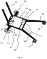
- FIG. 1 shows a patient handling apparatus 10.
- the patient handling apparatus 10 comprises a base 30 with a frame 31.
- the base 30 may be movable relative the ground.
- the base 30 may be provided with wheels 32, 33 adapted to allow movement of the base, i.e. the patient handling apparatus 10, relative the ground.
- the patient handling apparatus 10 further comprises a patient support device 20.
- the patient handling apparatus 10 comprises a patient support device 20.
- the patient support device 20 is adapted to support a patient, i.e. support the weight of said patient.
- the patient support device 20 is movable relative to the base 30.
- the patient support device 20 is thus movably mounted to the frame 31.
- the patient support device 20 may for example be movable between an upright position and an inclined position. In the inclined position, patient support device 20 is inclined backwards or forwards in the inclined position relative to the upright position by means of a guiding arrangement 70.
- An upright position may herein be defined as a position wherein the patient supported by the patient support device 20 is in an upright position. Accordingly, the spline of the patient extends substantially in a vertical direction.
- An inclined position may herein be defined as a position wherein the patient supported by the patient support device 20 is an inclined position, i.e. an inclined position relative the upright position.
- the inclined position is thus a position wherein the patient is tilted, i.e. the spline of the patient is tilted, relative a vertical axis of the patient handling apparatus.
- the patient support device 20 may be movable between a raised position and a lowered position. Thus, the patient support device 20 may be movable along a vertical direction.
- the patient support device 20 may comprise a seat support portion 21.
- the seat support portion 21 is adapted to support the rear of a patient supported by the patient support device 20.
- the patient support device 20 may further comprise a back support portion 22.
- the back support portion 22 is adapted to support the back of a patient when the patient is supported by the patient support device 20.
- the patient support device 20 may be in the form of a chair support.
- the patient support device 20 is thus adapted to support a seated patient.
- the back support portion 22 and the seat support portion 21 may be substantially orthogonal to each other.
- the patient support device 20 may further comprise a calf supporting section pivotally mounted to the seat support portion 21. Said calf supporting section is adapted to support the calves of a patient supported by the patient support device 20.
- the patient handling apparatus comprises a weighing arrangement 90 for weighing a patient supported by the patient support device 20.
- supported herein may refer to any type of supporting of the patient.
- the type of support provided by the patient support device 20 may differ based on the patient's posture and position as well as the type of patient support device 20.
- the patient may be supported by the patient support device 20 by being suspended from the patient support device 20 or the patient support device 20 constituting a seating surface for a patient in a seated position.
- the weighing arrangement comprises a sub frame 91 and a plurality of load sensors 95, 96, 97.
- the sub frame 91 is arranged on the load sensors 95, 96, 97.
- the load sensors 95, 96, 97 defines a weighing area S.
- the patient support device 20 is mounted to the frame 31 such that a center of gravity G of the patient, when the patient is supported by the patient support device 20, is positioned outside the weighing area S.
- the patient support device 20 is mounted to the frame 31 such that a central point of the seat support portion 21 (depicted in Figure 1 ) of the patient support device 20 is positioned outside the weighing area S in at least one position of the patient support device 20 (shown in Figure 2 ).
- the weighing arrangement is less sensitive to flexing or bending compared to a conventional weighing arrangement wherein the center of gravity of the patient is positioned inside the weighing area, particularly if the sub frame 91 is adapted to be more rigid than the frame 31 and/or other components of the patient handling apparatus which carries the load of the weight of the patient. This is due to frame taking the load from the patient and the offset patient not exerting any weight directly toward the sub frame.
- the weighing arrangement and sub frame may be considerably smaller while providing sufficient functionality, allowing for a more compact patient handling apparatus.
- the weighing arrangement according to the invention allows the patient to be weighed when the patient support device is at different vertical and tilted positions in relation to the load sensors while the sensors still provides a correct measurements and the calculated weight is accurate.
- the uneven distribution of load between the load sensors would cause the calculated weight to be imprecise or incorrect.
- the mounting of the sub frame on the load sensors prevents the patient handling apparatus to fall over or tip in case a load cell brakes, since a broken load cell only will cause the sub frame to drop in towards the frame, which does not affect the rest of the patient handling apparatus.
- the central point of the seat support portion 21 is positioned outside the weighing area S of the patient support device 20 in multiple positions of the patient support device 20. In one embodiment, the central point of the seat support portion 21 is positioned outside the weighing area S of the patient support device 20 in all positions of the patient support device 20. In one embodiment, the patient support device 20 is stationary, whereby the central point of the seat support portion 21 is stationary mounted outside the weighing area S.
- the base 30 comprises a horizontally extending portion 80.
- the frame 31 extends in a substantially vertical direction.
- the horizontally extending portion 80 may be arranged to be adjacent to the floor, the frame 31 extending upwards from said horizontally extending portion 80.
- the horizontally extending portion 80 may be provided with the wheels 32, 33.
- the base 30 may thus be a movable base 30, in an alternative embodiment the base 30 may be a stationary base.
- the weighing area S extends parallel to the horizontally extending portion 80.
- the weighing area S may form a delimited plane SP, i.e. a plane delimited by the load sensors 95, 96 97, extending in a horizontal direction.
- a central position axis CA extends through the central position of the seat support portion 21.
- the central position axis CA extends in a vertical direction.
- the central position axis CA may be parallel to a normal, i.e. normal vector, SN of the delimited plane SP.
- the central position axis CA may extend at an offset horizontal distance D from said normal SN.
- the normal SN may extend from an outer edge of the delimited plane SP proximal to the central position axis CA
- the gravitational force from the center of gravity of a patient supported by the patient support device 20 extends parallel to the central position axis CA Preferably, the gravitational force extends in a direction aligned with the central position axis CA.
- the load sensors may be arranged on the base 30 or the horizontally extending portion 80 of the base 30.
- a first part of each load sensor 95, 96, 97 is arranged on the base 30, whereby the sub frame 91 is arranged on a second part of each load sensor 95, 96, 97.
- Said second part of each load sensor 95, 96, 97 is solely supported by the sub frame 91. Accordingly, the second part of each load sensors 95, 96, 97 does not rest on the base 30.
- a bottom side of the load sensors 95, 96, 97 is mounted to the base 30 or the horizontally extending portion 80 of the base 30.
- the sub frame 91 is arranged on a top side of the load sensors 95, 96, 97.
- the horizontally extending portion 80 may comprise a support structure.
- the sub frame 91 may be arranged inside said support structure.
- the support structure may comprise a plurality of elongated support members forming a rectangular support structure.
- the sub frame 91 is arranged on a first load sensor 97, a second load sensor 95 and a third load sensor 96.
- the first load sensor 97 is arranged proximal to the frame 31, i.e. the position where the frame extends from the horizontally extending portion 80.
- Each of the second load sensor 95 and the third load sensor 96 is arranged distally from the frame 31 at a distance from the first load sensor 96 extending across the weighing area S. In one embodiment, said distance may extend along the horizontally extending portion 80.
- the first load sensor 97 may be arranged at a first edge 201 of the weighing area S, i.e. the delimited plane SP.
- the second load sensor 95 and the third load sensor 96 may be arranged along a second edge 202 of the weighing area S, i.e. the delimited plane SP.
- the second edge 202 is opposite to the first edge 201.
- the first edge 201 may be proximal to the frame 31, i.e. the position where the frame 31 extends from the horizontally extending portion 80.
- the second edge 202 may be distal to the frame 31, i.e. the position where the frame extends from the horizontally extending portion 80.
- the sub frame 91 may comprise a first sub frame member 36 and a second sub frame member 39.
- the second sub frame member 39 is arranged at a distance extending across the weighing area S from the first sub frame member 36.
- the first sub frame member 36 may be arranged at the first edge 201 of the weighing area S and the second sub frame member 39 may be arranged at the second edge 202 of the weighing area S.
- said distance may extend along the horizontally extending portion 80.
- the second sub frame member 39 extends parallel to the first sub frame member 36.
- the sub frame 91 may further comprise a third sub frame member 37 and a fourth sub frame member 38.
- the third sub frame member 37 is connected to the first sub frame member 36 and the second sub frame member 39.
- the fourth sub frame member 38 is connected to the first sub frame member 36 and the second sub frame member 39.
- the third and fourth frame member 37, 38 may interconnect the first sub frame member 36 and the second sub frame member 39.
- the third sub frame member 37 may extend parallel to the fourth sub frame member 38.
- the first sub frame member 36 may be arranged on the first load sensor 97.
- the second sub frame member 39 and/or the third sub frame member 37 may be arranged on the second load sensor 95.
- the second sub frame member 39 and/or the fourth sub frame member 38 is arranged on the third load sensor 96.
- the sub frame 91 may be connected to the base 30 by means of the load sensors 95, 96, 97.
- the sub frame 91 is only suspended to the base 30 by the load sensors 95, 96, 97.
- the load sensors 95, 96, 97 may be configured to measure the load, i.e. tension, between the base 30 and the sub frame 91.
- a first portion, e.g. a first end of each load sensor 95, 96, 97 may be connected to the base 30.
- a second portion, e.g. a second of each load sensor 95,96, 97 may be connected to the sub frame 91. Accordingly, the first end of each load sensor 95, 96, 97 may be fix to the base 30. The second end of each load sensor 95, 96, 97 may be fix to the sub frame 91.
- the load sensors 95, 96, 97 may be load cells. As is well known in the field load cells are a type of transducers, which converts load into an electric signal readable by a processing unit such as a control unit. Load cells may be of hydraulic, pneumatic or strain gauge type. Preferably, the load cells may be strain gauge load cells due to their cost-efficiency.
- the load sensors 95, 96, 97 may be beam load cells such as double-ended shear beams.
- the first load sensor 97 may be arranged proximal to the frame 31.
- the first load sensor 97 is arranged and balanced such that a downwards directed load applied to the central position C of the seat support portion 21 results in a tension load in said first load sensor 97.
- the tension load may extend along the first load sensor 97 in the delimited plane SP.
- the tension load may at least partially extend towards the central portion C of the seat support portion 21, i.e. at least one load component vector of said load extends towards the central portion P.
- a central portion of the first sub frame member 36 is arranged on said first load sensor 97.
- the first sub frame member 36 may be arranged on a plurality of load sensors, each being arranged and balanced such that a downwards directed load applied to the central position C of the seat support portion 21 results in a tension load in the load sensors.
- the tension load extend along each of the load sensors in the delimited plane SP.
- the first load sensor 97 may connect to the base 30, i.e. the horizontally extending portion 80 at a position between the first sub frame member 36 and the second and third load sensor 95, 96.
- the second load sensor 95 may be arranged distally from the frame 31.
- the second load sensor 95 is arranged adjacent to the connection between the third sub frame member 37 and the second sub frame member 39.
- the second load sensor 95 is arranged and balanced such that the measurable tension in the first load sensor causes a resulting measurable load in said second load sensor 95 via the sub frame 91.
- the resulting tension load extend along the second load sensor 95 in the delimited plane SP.
- the third load sensor 96 may be arranged distally from the frame 31.
- the third load sensor 96 is arranged adjacent to the connection between the fourth sub frame member 38 and the second sub frame member 39.
- the third load sensor 96 is arranged and balanced such that the measurable tension in the first load sensor causes a resulting measurable load in said third load sensor 96 via the sub frame 91.
- the resulting tension load extend along the third load sensor 96 in the delimited plane SP.
- only the second sub frame member 39 is arranged on the second load sensor 95 and the third load sensor 96. In one embodiment, the second load sensor 95 and third load sensor 96 solely connects the second sub frame member 39 with the base.
- the third sub frame member 37 and second sub frame member 39 are arranged on the second load sensor 95 and the fourth sub frame member 38 and second sub frame member 39 are arranged on the third load sensor 96.
- the second load sensor 95 connects the third sub frame member 37 and the second sub frame member 39 to the base.
- the third load sensor 96 connects the fourth sub frame member 38 and the second sub frame member 39 to the base.
- the patient handling apparatus may further comprise adjustable fixating means 150.
- the adjustable fixating means 150 may be adapted to adjustably fixate the load sensors 95, 96, 97 to the sub frame 91 and/or to the base 30.
- the tension in the load sensors 95, 96, 97 may be set by means of said adjustable fixating means 150 in a simple and user-friendly manner making the balancing of the weighing arrangement more efficient. This is particularly advantageous if the load sensors are load cells and more preferably beam load cells.
- Balancing herein refers to the process of setting up a pre-set tension, i.e. load, in each load sensor and thus distributing the tension between the sub frame 91 and the base 30 via said load sensors to a pre-set reference value, i.e. load value.
- the adjustable fixating means 150 is adapted to control a fixating force holding the load sensor to the base 30 and/or sub frame 91.
- balancing of the weighing arrangement may be achieved by adjusting the adjustable fixating means and consequently the fixating force.
- one of the portions of each load sensor is a fix end, i.e. fixedly mounted to the base 30 or the sub frame 91 and the other portion of each load sensor is connected of the other of the base 30 and the sub frame 91 by means of the adjustable fixating means.
- the adjustable fixating means 150 may comprise adjustable fixating members 155, 156, 157.
- the adjustable fixating members 155, 156, 157 are adapted to adjustably fixate each of the load sensors 95, 96, 97 to the sub frame 91 and/or the base 30.
- the load sensors 95, 96, 97 may be mounted to the sub frame 91 and/or the base 30 by means of said adjustable fixating members 155, 156, 157, whereby adjustment of said adjustable fixating members 155, 156, 157 causes adjustment of the fixating force holding each of the load sensors 95, 96, 97 to the base 30 and/or sub frame 91.
- the adjustable fixating members 155, 156, 157 are adjustable fastening elements, such as bolts or screws or similar, connecting each of the load sensors 95, 96, 97 to the base and/or sub frame 91. By providing torque to the adjustable fastening elements, the fixating force on the load sensor increases or decreases.
- the central position C of the seat support portion 21 of the patient support device 20 is positioned outside the weighing area Sin at least one position of the patient support device.
- the seat support portion 21 may be considered a portion of the patient support device adapted to support the rear of a patient supported the patient support device 20.
- the central point is consequently a centrally disposed point of said portion.
- the central point C is thus positioned at an offset horizontal distance relative the weighing area S in at least one position of the patient support device 20.
- the offset horizontal distance may be defined as the offset horizontal distance D between the normal SN and the central position axis CA as previously described with reference to Figure 1 .
- the normal SN may thus extend from a position along the second edge 202 of the weighing area S, i.e. a second edge of the delimited plane SP.
- the central point C of the seat support portion 21 is relatively aligned with the center of gravity G (as depicted in Figure 1 ) of a patient seated on said seat support portion 21, whereby it is ensured that the center of gravity G of the patient is outside the weighing area S as long as the central point C of the seat support portion 21 is outside said weighing area S.
- the seat support portion 21 may be a separate element of the patient support device 20 or an integrated portion of a larger support part of the patient support device 20 which supports the rear of the patient supported by said patient support device 20.
- the weighing area S forms the delimited plane SP defined by the load sensors 95, 96, 97, i.e. the connections between said load sensors 95, 96, 97 and the sub frame 91.
- the weighing area S may be aligned with the sub frame 91.
- the sub frame 91 may form a rectangular shape.
- the weighing area S may form a rectangular delimited plane SP aligned with said sub frame 91.
- the weighing area S may be parallel to said sub frame 91.
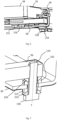
- FIG. 5 depicts a partial cross-section of the patient handling apparatus.
- the patient handling apparatus may comprise a securing arrangement 120.
- the securing arrangement 120 may be adapted to upon actuation lock the position of the sub frame 91 relative the base 30.
- the securing arrangement 150 allows for keeping the sub frame 91 in a set position relative the base 30 once the calibration and balancing has been performed.
- the risk for the user having to re-calibrate and re-balance the weighing arrangement due to the sub frame 91 and base 30 moving relative each other by accident, impact or wear of the load sensors is reduced.
- the securing arrangement 120 may comprise a securing member 123 movably mounted to the base 30 and/or sub frame 91 for engaging the other of the base 30 or sub frame 91 and thereby fixate the base 30 to the sub frame 91.
- the securing arrangement 120 may comprise at least one actuating member 121, 122 adapted to move said securing member 123 between an actuated position and a non-actuated position. In the actuated position, the securing member 123 fixates the sub frame 91 to the base 30. In the non-actuated position, the securing member 123 does not provide said fixation between the sub frame 91 and the base 30.
- the at least one actuating member 121, 122 may be at least one actuation screw.
- Said actuation screw may extend in a vertical direction through an aperture of the securing member 123, whereby rotation of said screw in a first direction moves the engagement member 123 towards the actuated position and in a second direction moves the engagement member 123 away from said actuated position.
- the securing member 123 may be a spring-loaded clamp.
- the spring-loaded clamp may be arranged to selectively lock, i.e. secure, the position of the sub frame 91 relative the base 30.
- the securing member is adapted to engage the first sub frame member 36, i.e. the sub frame member most adjacent to the frame 31.
- the patient handling apparatus may comprise a load sensor fastening arrangement for setting the correct tension of the connection between the load sensor and the base.
- a load sensor fastening arrangement is provided.
- At least one of the load sensors 95, 96, 97 is mounted to the base 30 by means of a load sensor fastening arrangement.
- each of the load sensors 95, 96, 97 is mounted to the base 30 by means of a load sensor fastening arrangement.
- the load sensor fastening arrangement comprises a fastening element 159.
- the fastening element 159 is adjustable along a tensioning axis T for setting the tension between the load sensor 95, 96, 97 and the base 30. As depicted in Figure 6-8 , the fastening element 159 may extend along the tensioning axis T.
- the load sensor fastening arrangement further comprises supporting means 310, 315, 320, 325.
- the supporting means comprises a support element 310, 320, i.e. at least one support element 310, 320 and a support member 315, 325, i.e. at least one support member 315, 325.
- the support element 310, 320 or the support member 315, 325 has a bowl shaped surface.
- the other of the support element 310, 320 or the support member 315, 325 has a dome shaped surface.
- the dome shaped surface may have a shape corresponding to the bowl shaped surface.
- the bowl shaped surface and dome shaped surface may be spherical.
- the bowl shaped surface and dome shaped surface may face directions extending along the tensioning axis T.
- the tensioning axis T may extend vertically.
- the dome shaped surface and bowl shaped surface may face each other.
- the dome shaped surface and bowl shaped surface may face each other relative the tensioning axis T.
- the curvature of the bowl shaped surface and the curvature of the dome shaped surface engage such that a convex surface of the support member or support element engages with a corresponding concave surface of the other of the support member or support element.
- the support member and support element may each comprise a substantially planar surface extending orthogonally to the tensioning axis T.
- the substantially planar surface may thus be arranged opposite to the bowl shaped surface or dome shaped surface of the support member or support element.
- the curvature of the bowl shaped surface is arranged to engage the curvature of the dome shaped surface when the fastening element 159 is adjusted for increasing the tension between the load sensor 95, 96, 97 and the base 30.
- the curvature of the bowl shaped surface or dome shaped surface of the support element 310, 320 is arranged to be brought into contact with the curvature of the other of the bowl shaped surface and the dome shaped surface of the support member 315, 325 when the fastening element 159 is adjusted for increasing the tension between the load sensor 95, 96, 97 and the base 30.
- the support member and support element are arranged to engage upon adjustment of the fastening element 159 for increasing the tension between the load sensor 95, 96, 97 and the base 30.
- the bowl and dome shaped surface creates a pivot point for the mounting of the load sensor which reduces the strain between the sub frame and the base. Further, the surfaces provides an indication of the correct tensioning and positioning of the load sensor. This makes it easier for an operator to match the individual positioning of the load sensors and consequently allows for easier calibration of the weighing arrangement.
- a geometrical center point of the curvature of the bowl shaped surface of the support element 310, 320 or the support member 315, 325 may be arranged along an axis extending parallel to or in alignment with the tensioning axis T.
- a geometrical center point of the curvature of the dome shaped surface of the other of the support element 310, 320 and the support member 315, 325 may also be arranged along said axis extending parallel to or in alignment with the tensioning axis T.
- the curvature of the dome and bowl shaped surface may be arranged orthogonally to said axis extending parallel to or in alignment with the tensioning axis T.
- said dome or bowl shaped surface may be orthogonal to said axis.
- the support element and support member may be arranged orthogonally to said axis extending parallel to or in alignment with the tensioning axis T.
- the dome shaped surface and the bowl shaped surface may be arranged to form a spherical joint upon engagement.
- adjustment of the fastening element 159 for increasing the tension between the load sensor 95, 96, 97 and the base 30 along the tensioning axis T causes fixation of said spherical joint.
- the dome shaped surface of the support element 310, 320 is arranged to engage the bowl shaped surface of the support member 315, 325 when the fastening element 159 is adjusted for increasing the tension between the load sensor 95, 96, 97 and the base 30.
- the load sensor 95, 96, 97 is mounted to the base 30 by means of the load sensor fastening arrangement and a fixed connection to the sub frame.
- a first end of the load sensor 95, 96, 97 is connected to the base 30 by means of the load sensor fastening arrangement and a second end is connected to the sub frame by means of the fix connection.
- the support element 310, 320 is provided with a through-hole.
- the support member 315, 325 is also provided with a through-hole.
- the fastening element 159 may extend through said through-holes.
- the supporting means may be arranged along the tensioning axis T.
- the support member and support element may be arranged as protruding elements provided on the load sensor 95, 96, 97 and the base 30.
- the support member and support element may be arranged offset from the fastening element 159. Compared to such an arrangement, having the fastening element extending through the holes allows for a less complex and more user-friendly mounting of the load sensors.
- the fastening element 159 may extend in a hole provided in the base 30 and in a hole provided in the load sensor 95, 96, 97.
- the load sensor 95, 96, 97 may be provided with a through-hole, whereby the fastening element 159 may extend through said load sensor 95, 96, 97.
- the fastening element 159 may comprise a fixating portion 158.
- the supporting means comprises a first support element 310 and a first support member 315 arranged between the fixating portion 158 and the load sensor 95, 96, 97 or the base 30.
- the first support element 310 and the first support member 315 are arranged between the base 30 and the fixating portion 158.
- the supporting means may further comprise a second support element 320 and second support member 325 arranged between the load sensor 95, 96, 97 and the base 30.
- the first and second support element are arranged to engage the first and second support member, respectively. Having support means in the form of a first and second support element and member allows for easier rotation of the fixating element around its center and further accommodates pivoting of the fastening element.
- planar surfaces of the support element 310, 320 and the support member 315, 325 may abut to corresponding planar surfaces of the load sensor, base or fastening element when the load sensor is in a mounted position.
- the fastening element may be provided with threads for engaging corresponding threads in the base 30.
- the fixating element may be a screw.
- the fixating portion may thus be a head of the screw.
- the support element(s) and support member(s) 310, 315, 320, 325 may be washers. The washers may be arranged coaxially with the fastening element.
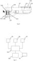
- FIG. 9 depicts a schematic drawing of the control unit and associated components of the patient handling apparatus according to an embodiment
- the patient handling apparatus comprises a control unit 101 operatively connected to the load sensors 95, 96, 97.
- the control unit 101 is configured to calculate the weight of a patient supported by the patient support device 20 based on sensor signals from the load sensors 95, 96, 97.
- the weight of the patient may be accurately calculated even though relatively simple and cost efficient load sensors are used, since only the tension between the base and the sub frame is required to be measured for an accurate calculated weight.
- the sensor signals from the load sensors 95, 96, 97 are indicative of the load applied to each of said load sensors 95, 96, 97. Further, the sensor signals from the load sensors 95, 96, 97 are indicative of the tension between the sub frame 91 and the base 30 through each of the load sensors 95, 96, 97.
- control unit 101 may be configured to compare load data obtained from the sensor signals from the load sensors 95, 96, 97 when a patient is mounted to the patient support device with 20 reference load data obtained from the sensor signals from said load sensors 95, 96, 97 from when no patient is mounted to the patient support device 20 and thereby obtain the weight of said patient supported by the patient support device 20.
- the reference load data may be obtained when the weighing arrangement has been calibrated and balanced.
- the reference load data may also be used during re-calibrating and re-balancing of said weighing arrangement.
- the control unit is configured to calculate the weight of the patient supported by the patient support device by calculating a weight value indicating the weight of said patient supported by the patient support device based on the sensor signals from the load sensors 95, 96, 97.
- the control unit may comprise a processor for calculating said weight.
- control unit 101 may be configured to convert the sensor signals from the load sensors 95, 96, 97 to load data. In one embodiment, this may be performed by a converter operatively connected to the load sensors and control unit.
- the patient handling apparatus may further comprise an indicating device 102 configured to display the weight calculated by the control unit 101.
- the indicating device 102 may be in the form of a display with a graphical user interface (GUI).
- GUI graphical user interface
- the indicating device 102 is operatively connected to the control unit 101 for presenting the weight.
- the indicating device 102 may comprise a device configured to generate an audible or visible alarm or alert when the calculated weight of the patient exceeds a threshold weight.
- the indicating device 102 is configured to display the load data obtained from the sensor signals, from the load sensors 95, 96, 97.
- the load data may represent the load, i.e. tension, on each of the load sensors 95, 96, 97. This is particularly advantageous during balancing and calibration of the weighing arrangement since it allows for tracking of the load exerted on each load sensor 95, 96, 97 during said balancing and calibration. This is particularly advantageous in combination with the adjustable fixating means described with reference to Figure 3 since it allows for a user to control said adjustable fixating means while using the indicating device as reference during balancing of the weighing arrangement.
- the load data may be in the form of force tensors on each of the load sensors 95, 96, 97.
- the indicating device 102 is configured to only display the aforementioned calculated weight. In one embodiment, the indicating device 102 is configured to display the weight and load data. In one embodiment, the indicating device 102 is configured to display only the load data.
- the indicating device 102 is further configured to display the reference load data.
- the reference load data may be displayed together with the load data further helping the user to achieve a correct balancing of the weighing arrangement.
- control unit 101 may be configured to obtain load data from said sensor signals from the load sensors 95, 96, 97. Further, the control unit 101 may be configured to calculate the weight value indicating the weight of the patient supported by the patient support device based on said load data.
- the control unit 101 may be mounted to the base 30 of the patient handling apparatus or may be a separate device.
- control unit 101 may comprise a communication interface, whereby the control unit 101 is further configured to transfer the aforementioned calculated weight value to an external device, such as a smart phone or computer.
- an external device such as a smart phone or computer.
- This may be an alternative to the indicating device 102 or be utilised together with said indicating device 102.
- a patient handling apparatus 10 is provided. As previously described with reference to Figure 1 , the patient handling apparatus 10 comprises the base 30 with the frame 31. The patient handling apparatus further comprises the patient support device 20. The patient handling apparatus further comprises the weighing arrangement 90 for weighing a patient supported by the patient support device 20. The weighing arrangement comprises the sub frame 91 and the plurality of load sensors 95, 96, 97, said sub frame 91 being arranged on the load sensors 95, 96, 97. The load sensors 95, 96, 97 defines the weighing area S.
- the patient support device 20 is mounted to the frame 31 at a mounting point P such that said mounting point P is positioned outside the weighing area S (as depicted in Figure 2-4 ) in at least one position of the patient support device 20.
- the same advantages may be achieved even with a flexible and hanging type of patient support device, since it allows for positioning of the center of gravity G of the patient outside the weighing area S (due to the mounting point P being relatively aligned said center of gravity of the patient).
- the patient support device 20 is a patient sling.
- the mounting point P may comprise a spreader bar or hanger for mounting of said sling.
- the aforementioned patient handling apparatus may comprise any of the features previously described with reference to Figure 1 to 8 .
- a patient handling apparatus comprises the load sensor fastening arrangement described with reference to Figure 6 to 8 .
- a patient handling apparatus 10 is provided.
- the patient handling apparatus comprises a base 30 with a frame 31 and a patient support device 20 mounted to the frame 31.
- the patient handling apparatus 10 further comprises a weighing arrangement for weighing a patient supported by the patient support device 20.
- the weighing arrangement 90 comprises a sub frame 91 and a plurality of load sensors 95, 96, 97.
- the sub frame 91 is connected to the base 30 by the load sensors 95, 96, 97.
- the sub frame 91 is arranged on the load sensors 95, 96, 97.
- At least one of the load sensors 95, 96, 97 is mounted to the base 30 by means of a load sensor fastening arrangement.
- the load sensor fastening arrangement comprises a fastening element 159.
- the fastening element 159 is adjustable along a tensioning axis T for setting the tension between the load sensor 95, 96, 97 and the base 30.
- the load sensor fastening arrangement further comprises supporting means 310, 315, 320, 325.
- the supporting means 310, 315, 320, 325 comprises a support element 310, 320 and a support member 315, 325.
- the support element 310, 320 or the support member 315, 325 has a bowl shaped surface.
- the other of the support element 310, 320 and the support member 315, 325 has a dome shaped surface.
- the curvature of the bowl shaped surface is arranged to engage the curvature of the dome shaped surface when the fastening element 159 is adjusted for increasing the tension between the load sensor 95, 96, 97 and the base 30.
- the load sensor fastening arrangement may comprise any of the features described with reference to Figure 6-8 .
- the patient handling apparatus 10 comprises the base 30 with the frame 31 and the patient support device 20.
- the weighing arrangement comprises the sub frame 91 and the plurality of load sensors 95, 96, 97.
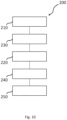
- the method comprises obtaining 210 sensor signals from the load sensors 95, 96, 97.
- the method further comprises adjusting 220 adjustable fixating means 150 to adjust the fixation of the load sensors 95, 96, 97 based on the sensor signals.
- the adjustable fixating means 150 for adjusting the fixation of the load sensors 95, 96, 97 may be the adjustable fixating means 150 described with reference to Figure 5 .
- the method further comprises presenting 230 load data obtained from the sensor signals from the load sensors 95, 96, 97 on an indicating device 102 of the patient handling apparatus 10.
- the indicating device 102 may be the indicating device 102 described with reference to Figure 6 .
- the weighing arrangement may be adjusted 220 based on the presented load data from the load sensors 95, 96, 97 on the indicating device 102 of the patient handling apparatus 10.
- the presenting 230 of the sensor signals from the load sensors 95, 96, 97 may further comprise individually presenting the load data obtained from the sensor signals from each load sensor 95, 96, 97 on the indicating device 102 of the patient handling apparatus 10.
- the method may further comprise actuating 240 a securing arrangement 120 to lock the position of the sub frame 91 relative the base 30.
- the method may comprise actuating 240 said securing arrangement after the adjusting 220 of the adjustable fixating means 150 to adjust the fixation of the load sensors 95, 96, 97 based on the sensor signals from the load sensor 95, 96, 97.
- the securing arrangement 120 may be the securing arrangement as described with reference to Figure 5 .
- the method may further comprise calibrating 250 the patient handling apparatus by means of suspending a reference weight to the patient support device 20.
- the weighing arrangement is tested in terms of giving a correct estimation and calculation of the weight.
- the step of calibrating 250 may be performed after the adjusting 220 of the adjustable fixating means 150.
Landscapes
- Health & Medical Sciences (AREA)
- Nursing (AREA)
- Life Sciences & Earth Sciences (AREA)
- Animal Behavior & Ethology (AREA)
- General Health & Medical Sciences (AREA)
- Public Health (AREA)
- Veterinary Medicine (AREA)
- Physics & Mathematics (AREA)
- General Physics & Mathematics (AREA)
- Invalid Beds And Related Equipment (AREA)
- Measurement Of The Respiration, Hearing Ability, Form, And Blood Characteristics Of Living Organisms (AREA)
- Sampling And Sample Adjustment (AREA)
- Acyclic And Carbocyclic Compounds In Medicinal Compositions (AREA)
- External Artificial Organs (AREA)
Claims (21)
- Patientenhandhabungseinrichtung (10), umfassend eine Basis (30) mit einem Rahmen (31) und eine Patientenunterstützungsvorrichtung (20),die Patientenhandhabungseinrichtung (10), ferner umfassend eine Wiegeanordnung (90) zum Wiegen eines durch die Patientenunterstützungsvorrichtung (20) unterstützten Patienten, wobei die Wiegeanordnung (90) einen Teilrahmen (91) und eine Vielzahl von Lastsensoren (95, 96, 97) umfasst, wobei der Teilrahmen (91) auf den Lastsensoren (95, 96, 97) angeordnet ist, wobei die Lastsensoren (95, 96, 97) einen Wiegebereich (S) definieren, wobei die Patientenunterstützungsvorrichtung (20) an dem Rahmen (31) so montiert ist, dass ein zentraler Punkt (C) eines Sitzunterstützungsabschnitts (21) der Patientenunterstützungsvorrichtung (20) außerhalb des Wiegebereichs (S) in mindestens einer Position der Patientenunterstützungsvorrichtung (20) positioniert ist,gekennzeichnet dadurch,dass der Teilrahmen (91) mit der Basis (30) mittels der Lastsensoren (95, 96, 97) verbunden ist.
- Patientenhandhabungseinrichtung (10) gemäß Anspruch 1, ferner umfassend eine Steuereinheit (101), die betriebsfähig mit den Lastsensoren (95, 96, 97) verbunden ist, wobei die Steuereinheit (101) dazu konfiguriert ist, das Gewicht eines von der Patientenunterstützungsvorrichtung (20) unterstützten Patienten auf Basis von Sensorsignalen von den Lastsensoren (95, 96, 97) zu berechnen.
- Patientenhandhabungseinrichtung (10) gemäß Anspruch 2, ferner umfassend eine Anzeigevorrichtung (102), die dazu konfiguriert ist, das von der Steuereinheit (101) berechnete Gewicht darzustellen.
- Patientenhandhabungseinrichtung (10) gemäß einem der vorstehenden Ansprüche, wobei die Lastsensoren (95, 96, 97) Lastzellen sind.
- Patientenhandhabungseinrichtung (10) gemäß einem der Ansprüche 1 oder 2, wobei die Lastsensoren (95, 96, 97) Stablastzellen sind.
- Patientenhandhabungseinrichtung (10) gemäß Anspruch 5, wobei ein erstes Ende jeder der Lastsensoren (95, 96, 97) mit der Basis (30) verbunden ist und ein zweites Ende jedes Lastsensors (95, 96, 97) mit dem Teilrahmen (91) verbunden ist.
- Patientenhandhabungseinrichtung (10) gemäß einem der vorstehenden Ansprüche, ferner umfassend ein einstellbares Fixiermittel (150), die dazu geeignet sind, die Lastsensoren (95, 96, 97) einstellbar an dem Teilrahmen (91) und/oder der Basis (30) zu fixieren.
- Patientenhandhabungseinrichtung (10) gemäß einem der vorstehenden Ansprüche, ferner umfassend eine Sicherungsanordnung (120), die dazu geeignet ist, die Position des Teilrahmens (91) auf Betätigung hin relativ zu der Basis (30) zu verriegeln.
- Patientenhandhabungseinrichtung (10) gemäß einem der vorstehenden Ansprüche, wobei der Wiegebereich (S) sich parallel zu einem sich horizontal erstreckenden Abschnitt (80) erstreckt.
- Patientenhandhabungseinrichtung (10) gemäß einem der vorstehenden Ansprüche, wobei der Teilrahmen (91) auf einem ersten Lastsensor (97), einem zweiten Lastsensor (95) und einem dritten Lastsensor (96) angeordnet ist.
- Patientenhandhabungseinrichtung gemäß Anspruch 10, wobei der erste Lastsensor (97) proximal zu oder bei dem Rahmen (31) angeordnet ist, und jeder aus dem zweiten Lastsensor (95) und dem dritten Lastsensor (96) distal zu dem Rahmen (31) mit einem Abstand zu dem ersten Lastsensor (97), der sich über den Wiegebereich (S) erstreckt, angeordnet ist.
- Patientenhandhabungseinrichtung (10) gemäß Anspruch 10 oder 11, wobei der erste Lastsensor (97) an einer ersten Kante (201) des Wiegebereichs (S) angeordnet ist, und der zweite Lastsensor (95) und der dritte Lastsensor (96) entlang einer zweiten Kante (202) des Wiegebereichs (S) angeordnet sind, wobei die zweite Kante (202) gegenüber der ersten Kante (201) liegt.
- Patientenhandhabungseinrichtung gemäß einem der vorstehenden Ansprüche, wobei der Teilrahmen (91) ein erstes Teilrahmenelement (36) und ein zweites Teilrahmenelement (39) umfasst, wobei das zweite Teilrahmenelement (39) in einem Abstand, der sich über den Wiegebereich (S) erstreckt, zu dem ersten Teilrahmenelement (36) angeordnet ist.
- Patientenhandhabungseinrichtung (10) gemäß Anspruch 13, wobei der Teilrahmen (91) ein drittes Teilrahmenelement (37) und ein viertes Teilrahmenelement (38) umfasst, von denen jedes mit dem ersten Teilrahmenelement (36) und dem zweiten Teilrahmenelement (39) verbunden ist.
- Patientenhandhabungseinrichtung (10) gemäß Anspruch 13 oder 14, wobei das erste Teilrahmenelement (36) auf dem ersten Lastsensor (97) angeordnet ist, das zweite Teilrahmenelement (39) und/oder das dritte Teilrahmenelement (37) auf dem zweiten Lastsensor (95) angeordnet ist und das zweite Teilrahmenelement (39) und/oder das vierte Teilrahmenelement (38) auf dem dritten Lastsensor (96) angeordnet ist.
- Patientenhandhabungseinrichtung (10) gemäß Anspruch 1 oder 2, wobei die Patientenunterstützungsvorrichtung (20) eine Patientenschlinge ist.
- Verfahren (200) zum Ausgleichen einer Wiegeanordnung (90) einer Patientenhandhabungseinrichtung (10) gemäß Anspruch 1, das Verfahren umfassend:
Erhalten (210) von Sensorsignalen von den Lastsensoren (95, 96, 97) und Einstellen (220) eines einstellbaren Fixiermittels (150), um die Fixierung der Lastsensoren (95, 96, 97) auf Basis der Sensorsignale einzustellen. - Verfahren (200) gemäß Anspruch 17, ferner umfassend das Präsentieren (230) von Lastdaten, die aus den Sensorsignalen von den Lastsensoren (95, 96, 97) erhalten wurden, auf einer Anzeigevorrichtung (102) der Patientenhandhabungseinrichtung (10).
- Verfahren (200) gemäß Anspruch 18, wobei das Präsentieren (230) der Sensorsignale von den Lastsensoren (95, 96, 97) ferner das einzelne Präsentieren von Lastdaten, die aus den Sensorsignalen von jedem Lastsensor (95, 96, 97) erhalten wurden, auf der Anzeigevorrichtung (102) umfasst.
- Verfahren (200) gemäß einem der vorstehenden Ansprüche 17 bis 19, ferner umfassend das Betätigen (240) einer Sicherungsanordnung (120), um die Position des Teilrahmens (91) relativ zu der Basis (30) zu verriegeln.
- Verfahren (200) gemäß einem der Ansprüche 17 bis 20, ferner umfassend das Kalibrieren (250) der Patientenhandhabungseinrichtung (10) mittels Aufhängen eines Referenzgewichts an der Patientenunterstützungsvorrichtung (20).
Priority Applications (1)
| Application Number | Priority Date | Filing Date | Title |
|---|---|---|---|
| EP23162890.0A EP4218705B1 (de) | 2020-07-06 | 2021-06-17 | Patientenhandhabungsvorrichtung |
Applications Claiming Priority (2)
| Application Number | Priority Date | Filing Date | Title |
|---|---|---|---|
| SE2050850A SE544251C2 (en) | 2020-07-06 | 2020-07-06 | Patient handling apparatus comprising a weighing arrangement |
| PCT/EP2021/066413 WO2022008194A1 (en) | 2020-07-06 | 2021-06-17 | Patient handling apparatus |
Related Child Applications (2)
| Application Number | Title | Priority Date | Filing Date |
|---|---|---|---|
| EP23162890.0A Division-Into EP4218705B1 (de) | 2020-07-06 | 2021-06-17 | Patientenhandhabungsvorrichtung |
| EP23162890.0A Division EP4218705B1 (de) | 2020-07-06 | 2021-06-17 | Patientenhandhabungsvorrichtung |
Publications (3)
| Publication Number | Publication Date |
|---|---|
| EP4175602A1 EP4175602A1 (de) | 2023-05-10 |
| EP4175602B1 true EP4175602B1 (de) | 2024-10-02 |
| EP4175602C0 EP4175602C0 (de) | 2024-10-02 |
Family
ID=76553775
Family Applications (2)
| Application Number | Title | Priority Date | Filing Date |
|---|---|---|---|
| EP23162890.0A Active EP4218705B1 (de) | 2020-07-06 | 2021-06-17 | Patientenhandhabungsvorrichtung |
| EP21733966.2A Active EP4175602B1 (de) | 2020-07-06 | 2021-06-17 | Patientenhandhabungsvorrichtung |
Family Applications Before (1)
| Application Number | Title | Priority Date | Filing Date |
|---|---|---|---|
| EP23162890.0A Active EP4218705B1 (de) | 2020-07-06 | 2021-06-17 | Patientenhandhabungsvorrichtung |
Country Status (7)
| Country | Link |
|---|---|
| US (1) | US20230310242A1 (de) |
| EP (2) | EP4218705B1 (de) |
| AU (1) | AU2021306818A1 (de) |
| CA (1) | CA3188332A1 (de) |
| PL (2) | PL4175602T3 (de) |
| SE (1) | SE544251C2 (de) |
| WO (1) | WO2022008194A1 (de) |
Citations (9)
| Publication number | Priority date | Publication date | Assignee | Title |
|---|---|---|---|---|
| GB2127981A (en) | 1982-09-29 | 1984-04-18 | James Ind Ltd | Invalid hoists |
| US4926951A (en) | 1989-06-26 | 1990-05-22 | Ssi Medical Services, Inc. | Weigh bed |
| US5269388A (en) | 1991-11-12 | 1993-12-14 | Stress-Tek, Inc. | Weighing bed |
| US5279010A (en) | 1988-03-23 | 1994-01-18 | American Life Support Technology, Inc. | Patient care system |
| WO1994006390A1 (en) | 1992-09-15 | 1994-03-31 | Andermac, Inc. | Folding patient lift apparatus |
| US5859390A (en) | 1996-10-23 | 1999-01-12 | Hill-Rom, Inc. | Hospital bed scale mounting apparatus |
| US5892180A (en) | 1997-02-03 | 1999-04-06 | Medcare Products, L.C. | Patient hoist and scale |
| US6610935B1 (en) | 1999-11-17 | 2003-08-26 | Sieco, Inc. | Torque compensated weight sensing modules |
| WO2003079953A2 (en) | 2002-03-18 | 2003-10-02 | Hill-Rom Services, Inc. | Hospital bed with controlled inflatable portion of patient support |
Family Cites Families (11)
| Publication number | Priority date | Publication date | Assignee | Title |
|---|---|---|---|---|
| US4482783A (en) * | 1976-03-08 | 1984-11-13 | Hottinger Baldwin Measurements, Inc. | Patient weighing scale with hoist |
| US4420052A (en) * | 1980-08-27 | 1983-12-13 | Scale-Tronix, Inc. | Patient weighing scale |
| US4487276A (en) * | 1983-05-03 | 1984-12-11 | Swersey Burt L | Scale of flat construction |
| US6806430B2 (en) * | 2001-04-23 | 2004-10-19 | Ez Way, Inc. | Patient lift and scale |
| US7690059B2 (en) * | 2005-12-19 | 2010-04-06 | Stryker Corporation | Hospital bed |
| US7682079B2 (en) * | 2008-04-02 | 2010-03-23 | General Electric Company | Medical imaging system and method with integrated weight sensing |
| DE102011080691A1 (de) * | 2011-08-09 | 2013-02-14 | Siemens Aktiengesellschaft | Patiententisch zur Lagerung eines Patienten |
| DE102012201783B4 (de) * | 2012-02-07 | 2022-08-04 | Siemens Healthcare Gmbh | Verfahren zur Bestimmung der Patientenmasse eines Patienten mit einem Patiententisch und Einrichtung mit einem Patiententisch |
| US8987616B2 (en) * | 2012-06-05 | 2015-03-24 | Liko Research & Development Ab | Weight scale for a patient lift system, a control system for the weight scale, and a method for weighing a patient supported on the weight scale |
| JP6262379B1 (ja) * | 2017-02-22 | 2018-01-17 | 新光商事株式会社 | 荷重測定用ピンセンサ、見守り用ベッド及び見守りシステム |
| CN108955852B (zh) * | 2017-05-26 | 2024-08-13 | 梅特勒-托利多(常州)测量技术有限公司 | 偏重检测方法及平台秤 |
-
2020
- 2020-07-06 SE SE2050850A patent/SE544251C2/en unknown
-
2021
- 2021-06-17 PL PL21733966.2T patent/PL4175602T3/pl unknown
- 2021-06-17 PL PL23162890.0T patent/PL4218705T3/pl unknown
- 2021-06-17 AU AU2021306818A patent/AU2021306818A1/en active Pending
- 2021-06-17 WO PCT/EP2021/066413 patent/WO2022008194A1/en not_active Ceased
- 2021-06-17 CA CA3188332A patent/CA3188332A1/en active Pending
- 2021-06-17 EP EP23162890.0A patent/EP4218705B1/de active Active
- 2021-06-17 EP EP21733966.2A patent/EP4175602B1/de active Active
- 2021-06-17 US US18/014,491 patent/US20230310242A1/en active Pending
Patent Citations (9)
| Publication number | Priority date | Publication date | Assignee | Title |
|---|---|---|---|---|
| GB2127981A (en) | 1982-09-29 | 1984-04-18 | James Ind Ltd | Invalid hoists |
| US5279010A (en) | 1988-03-23 | 1994-01-18 | American Life Support Technology, Inc. | Patient care system |
| US4926951A (en) | 1989-06-26 | 1990-05-22 | Ssi Medical Services, Inc. | Weigh bed |
| US5269388A (en) | 1991-11-12 | 1993-12-14 | Stress-Tek, Inc. | Weighing bed |
| WO1994006390A1 (en) | 1992-09-15 | 1994-03-31 | Andermac, Inc. | Folding patient lift apparatus |
| US5859390A (en) | 1996-10-23 | 1999-01-12 | Hill-Rom, Inc. | Hospital bed scale mounting apparatus |
| US5892180A (en) | 1997-02-03 | 1999-04-06 | Medcare Products, L.C. | Patient hoist and scale |
| US6610935B1 (en) | 1999-11-17 | 2003-08-26 | Sieco, Inc. | Torque compensated weight sensing modules |
| WO2003079953A2 (en) | 2002-03-18 | 2003-10-02 | Hill-Rom Services, Inc. | Hospital bed with controlled inflatable portion of patient support |
Non-Patent Citations (2)
| Title |
|---|
| ANONYMOUS: "Sensortronics Model 60060", LOW PROFILE PLATFORM LOAD CELL, VISHAY PRECISION GROUP, INC., 5 June 2012 (2012-06-05), pages 1 - 3, XP093295700, Retrieved from the Internet <URL:https://intertechnology.com/Sensortronics/pdfs/60060.pdf> |
| ANONYMOUS: "SERVICE MANUAL Advance Series Bed From Hill-Rom", SERVICE MANUAL, HILL-ROM, INC., 1 September 1998 (1998-09-01), pages 1 - 698, XP093295692, Retrieved from the Internet <URL:https://www.ifixit.com/Document/qVamfQPiJpqVnUhv/Hill_Rom_Hospital_Bed_Advance_Series_Bed.pdf.pdf?referrer=wiki:423945> |
Also Published As
| Publication number | Publication date |
|---|---|
| CA3188332A1 (en) | 2022-01-13 |
| EP4175602A1 (de) | 2023-05-10 |
| SE2050850A1 (en) | 2022-01-07 |
| EP4218705B1 (de) | 2025-02-26 |
| SE544251C2 (en) | 2022-03-15 |
| WO2022008194A1 (en) | 2022-01-13 |
| PL4218705T3 (pl) | 2025-06-23 |
| AU2021306818A1 (en) | 2023-02-02 |
| PL4175602T3 (pl) | 2025-03-24 |
| EP4218705C0 (de) | 2025-02-26 |
| EP4175602C0 (de) | 2024-10-02 |
| EP4218705A1 (de) | 2023-08-02 |
| US20230310242A1 (en) | 2023-10-05 |
Similar Documents
| Publication | Publication Date | Title |
|---|---|---|
| US8887547B2 (en) | Weight applying unit for calibration and weight applying method for calibration | |
| EP0670480B1 (de) | Lastenmessanordnung | |
| US6201195B1 (en) | Patient hoist and scale | |
| EP2856090B1 (de) | Waage für ein patientenhebesystem, steuerungssystem für die waage und verfahren zum wiegen eines patienten auf der waage | |
| US6765154B2 (en) | Portable, adjustable bed weighing system | |
| US4533008A (en) | Livestock scale | |
| KR102421762B1 (ko) | 압력발판 및 손잡이를 이용한 신체 자세 측정시스템 및 이를 이용한 신체 자세 측정방법 | |
| EP4175602B1 (de) | Patientenhandhabungsvorrichtung | |
| KR102270146B1 (ko) | 족저압 및 와이어 로드를 바탕으로 피검자의 평형기능을 측정하는 자세 측정시스템 및 이를 이용한 자세 측정방법 | |
| JP2013527459A (ja) | 計量装置 | |
| US4492279A (en) | Infant health monitoring system | |
| EP0625696B1 (de) | Verfahren und Vorrichtung zum Wiegen einer mit einem Zugfahrzeug verbundenen Last | |
| NO833497L (no) | Invalideheis | |
| US20120128448A1 (en) | Lifting device with distributed-sensing scale | |
| CA1227632A (en) | Device for reproducibly ascertaining the posture of a free-standing human being | |
| CA2436154C (en) | Apparatus and method for monitoring force, especially force in labor and delivery | |
| US20250160735A1 (en) | Posture balance measurement system and posture balance measurement method using the same | |
| US20250134739A1 (en) | System and method to lift and weigh a patient | |
| EP3677883A1 (de) | Vorrichtung zum lösen eines angelhakens | |
| JP7682309B2 (ja) | 被検者用安全装置を用いた姿勢バランス測定システム、及びこれを用いた姿勢バランス測定方法 | |
| KR20250157802A (ko) | 4개의 발판에 로드셀을 부착하여 사용자의 무게중심을 측정하는 벨런스미터 | |
| US20240035877A1 (en) | Large weight scale for detecting possibility of bedsore, and bedsore detecting method | |
| RU2185094C2 (ru) | Силометрическая платформа | |
| US20230059508A1 (en) | Lift and weigh apparatus | |
| WO1990008945A1 (en) | Improvements to load sensing apparatus |
Legal Events
| Date | Code | Title | Description |
|---|---|---|---|
| STAA | Information on the status of an ep patent application or granted ep patent |
Free format text: STATUS: UNKNOWN |
|
| STAA | Information on the status of an ep patent application or granted ep patent |
Free format text: STATUS: THE INTERNATIONAL PUBLICATION HAS BEEN MADE |
|
| PUAI | Public reference made under article 153(3) epc to a published international application that has entered the european phase |
Free format text: ORIGINAL CODE: 0009012 |
|
| STAA | Information on the status of an ep patent application or granted ep patent |
Free format text: STATUS: REQUEST FOR EXAMINATION WAS MADE |
|
| 17P | Request for examination filed |
Effective date: 20221223 |
|
| AK | Designated contracting states |
Kind code of ref document: A1 Designated state(s): AL AT BE BG CH CY CZ DE DK EE ES FI FR GB GR HR HU IE IS IT LI LT LU LV MC MK MT NL NO PL PT RO RS SE SI SK SM TR |
|
| DAV | Request for validation of the european patent (deleted) | ||
| DAX | Request for extension of the european patent (deleted) | ||
| GRAP | Despatch of communication of intention to grant a patent |
Free format text: ORIGINAL CODE: EPIDOSNIGR1 |
|
| STAA | Information on the status of an ep patent application or granted ep patent |
Free format text: STATUS: GRANT OF PATENT IS INTENDED |
|
| INTG | Intention to grant announced |
Effective date: 20240319 |
|
| GRAJ | Information related to disapproval of communication of intention to grant by the applicant or resumption of examination proceedings by the epo deleted |
Free format text: ORIGINAL CODE: EPIDOSDIGR1 |
|
| STAA | Information on the status of an ep patent application or granted ep patent |
Free format text: STATUS: REQUEST FOR EXAMINATION WAS MADE |
|
| GRAS | Grant fee paid |
Free format text: ORIGINAL CODE: EPIDOSNIGR3 |
|
| STAA | Information on the status of an ep patent application or granted ep patent |
Free format text: STATUS: GRANT OF PATENT IS INTENDED |
|
| GRAP | Despatch of communication of intention to grant a patent |
Free format text: ORIGINAL CODE: EPIDOSNIGR1 |
|
| INTC | Intention to grant announced (deleted) | ||
| GRAA | (expected) grant |
Free format text: ORIGINAL CODE: 0009210 |
|
| STAA | Information on the status of an ep patent application or granted ep patent |
Free format text: STATUS: THE PATENT HAS BEEN GRANTED |
|
| INTG | Intention to grant announced |
Effective date: 20240808 |
|
| AK | Designated contracting states |
Kind code of ref document: B1 Designated state(s): AL AT BE BG CH CY CZ DE DK EE ES FI FR GB GR HR HU IE IS IT LI LT LU LV MC MK MT NL NO PL PT RO RS SE SI SK SM TR |
|
| REG | Reference to a national code |
Ref country code: GB Ref legal event code: FG4D |
|
| REG | Reference to a national code |
Ref country code: CH Ref legal event code: EP |
|
| REG | Reference to a national code |
Ref country code: IE Ref legal event code: FG4D |
|
| REG | Reference to a national code |
Ref country code: DE Ref legal event code: R096 Ref document number: 602021019606 Country of ref document: DE |
|
| U01 | Request for unitary effect filed |
Effective date: 20241018 |
|
| U07 | Unitary effect registered |
Designated state(s): AT BE BG DE DK EE FI FR IT LT LU LV MT NL PT RO SE SI Effective date: 20241104 |
|
| PG25 | Lapsed in a contracting state [announced via postgrant information from national office to epo] |
Ref country code: IS Free format text: LAPSE BECAUSE OF FAILURE TO SUBMIT A TRANSLATION OF THE DESCRIPTION OR TO PAY THE FEE WITHIN THE PRESCRIBED TIME-LIMIT Effective date: 20250202 Ref country code: HR Free format text: LAPSE BECAUSE OF FAILURE TO SUBMIT A TRANSLATION OF THE DESCRIPTION OR TO PAY THE FEE WITHIN THE PRESCRIBED TIME-LIMIT Effective date: 20241002 |
|
| PG25 | Lapsed in a contracting state [announced via postgrant information from national office to epo] |
Ref country code: ES Free format text: LAPSE BECAUSE OF FAILURE TO SUBMIT A TRANSLATION OF THE DESCRIPTION OR TO PAY THE FEE WITHIN THE PRESCRIBED TIME-LIMIT Effective date: 20241002 |
|
| PG25 | Lapsed in a contracting state [announced via postgrant information from national office to epo] |
Ref country code: GR Free format text: LAPSE BECAUSE OF FAILURE TO SUBMIT A TRANSLATION OF THE DESCRIPTION OR TO PAY THE FEE WITHIN THE PRESCRIBED TIME-LIMIT Effective date: 20250103 |
|
| PG25 | Lapsed in a contracting state [announced via postgrant information from national office to epo] |
Ref country code: CZ Free format text: LAPSE BECAUSE OF FAILURE TO SUBMIT A TRANSLATION OF THE DESCRIPTION OR TO PAY THE FEE WITHIN THE PRESCRIBED TIME-LIMIT Effective date: 20241002 |
|
| PG25 | Lapsed in a contracting state [announced via postgrant information from national office to epo] |
Ref country code: RS Free format text: LAPSE BECAUSE OF FAILURE TO SUBMIT A TRANSLATION OF THE DESCRIPTION OR TO PAY THE FEE WITHIN THE PRESCRIBED TIME-LIMIT Effective date: 20250102 |
|
| PG25 | Lapsed in a contracting state [announced via postgrant information from national office to epo] |
Ref country code: SM Free format text: LAPSE BECAUSE OF FAILURE TO SUBMIT A TRANSLATION OF THE DESCRIPTION OR TO PAY THE FEE WITHIN THE PRESCRIBED TIME-LIMIT Effective date: 20241002 |
|
| PLBI | Opposition filed |
Free format text: ORIGINAL CODE: 0009260 |
|
| PGFP | Annual fee paid to national office [announced via postgrant information from national office to epo] |
Ref country code: PL Payment date: 20250606 Year of fee payment: 5 |
|
| PGFP | Annual fee paid to national office [announced via postgrant information from national office to epo] |
Ref country code: GB Payment date: 20250618 Year of fee payment: 5 |
|
| PGFP | Annual fee paid to national office [announced via postgrant information from national office to epo] |
Ref country code: NO Payment date: 20250624 Year of fee payment: 5 |
|
| PLAX | Notice of opposition and request to file observation + time limit sent |
Free format text: ORIGINAL CODE: EPIDOSNOBS2 |
|
| PG25 | Lapsed in a contracting state [announced via postgrant information from national office to epo] |
Ref country code: SK Free format text: LAPSE BECAUSE OF FAILURE TO SUBMIT A TRANSLATION OF THE DESCRIPTION OR TO PAY THE FEE WITHIN THE PRESCRIBED TIME-LIMIT Effective date: 20241002 |
|
| 26 | Opposition filed |
Opponent name: BAXTER INTERNATIONAL INC. Effective date: 20250702 |
|
| U20 | Renewal fee for the european patent with unitary effect paid |
Year of fee payment: 5 Effective date: 20250627 |
|
| PGFP | Annual fee paid to national office [announced via postgrant information from national office to epo] |
Ref country code: CH Payment date: 20250701 Year of fee payment: 5 |
|
| PLBB | Reply of patent proprietor to notice(s) of opposition received |
Free format text: ORIGINAL CODE: EPIDOSNOBS3 |
|
| PG25 | Lapsed in a contracting state [announced via postgrant information from national office to epo] |
Ref country code: MC Free format text: LAPSE BECAUSE OF FAILURE TO SUBMIT A TRANSLATION OF THE DESCRIPTION OR TO PAY THE FEE WITHIN THE PRESCRIBED TIME-LIMIT Effective date: 20241002 |