EP2856090B1 - Waage für ein patientenhebesystem, steuerungssystem für die waage und verfahren zum wiegen eines patienten auf der waage - Google Patents
Waage für ein patientenhebesystem, steuerungssystem für die waage und verfahren zum wiegen eines patienten auf der waage Download PDFInfo
- Publication number
- EP2856090B1 EP2856090B1 EP13774232.6A EP13774232A EP2856090B1 EP 2856090 B1 EP2856090 B1 EP 2856090B1 EP 13774232 A EP13774232 A EP 13774232A EP 2856090 B1 EP2856090 B1 EP 2856090B1
- Authority
- EP
- European Patent Office
- Prior art keywords
- force
- leg
- patient
- slot
- coupled
- Prior art date
- Legal status (The legal status is an assumption and is not a legal conclusion. Google has not performed a legal analysis and makes no representation as to the accuracy of the status listed.)
- Active
Links
Images


Classifications
-
- A—HUMAN NECESSITIES
- A61—MEDICAL OR VETERINARY SCIENCE; HYGIENE
- A61G—TRANSPORT, PERSONAL CONVEYANCES, OR ACCOMMODATION SPECIALLY ADAPTED FOR PATIENTS OR DISABLED PERSONS; OPERATING TABLES OR CHAIRS; CHAIRS FOR DENTISTRY; FUNERAL DEVICES
- A61G7/00—Beds specially adapted for nursing; Devices for lifting patients or disabled persons
- A61G7/10—Devices for lifting patients or disabled persons, e.g. special adaptations of hoists thereto
- A61G7/1013—Lifting of patients by
- A61G7/1017—Pivoting arms, e.g. crane type mechanisms
-
- A—HUMAN NECESSITIES
- A61—MEDICAL OR VETERINARY SCIENCE; HYGIENE
- A61G—TRANSPORT, PERSONAL CONVEYANCES, OR ACCOMMODATION SPECIALLY ADAPTED FOR PATIENTS OR DISABLED PERSONS; OPERATING TABLES OR CHAIRS; CHAIRS FOR DENTISTRY; FUNERAL DEVICES
- A61G7/00—Beds specially adapted for nursing; Devices for lifting patients or disabled persons
- A61G7/10—Devices for lifting patients or disabled persons, e.g. special adaptations of hoists thereto
- A61G7/1073—Parts, details or accessories
- A61G7/108—Weighing means
-
- A—HUMAN NECESSITIES
- A61—MEDICAL OR VETERINARY SCIENCE; HYGIENE
- A61G—TRANSPORT, PERSONAL CONVEYANCES, OR ACCOMMODATION SPECIALLY ADAPTED FOR PATIENTS OR DISABLED PERSONS; OPERATING TABLES OR CHAIRS; CHAIRS FOR DENTISTRY; FUNERAL DEVICES
- A61G7/00—Beds specially adapted for nursing; Devices for lifting patients or disabled persons
- A61G7/10—Devices for lifting patients or disabled persons, e.g. special adaptations of hoists thereto
- A61G7/1013—Lifting of patients by
-
- A—HUMAN NECESSITIES
- A61—MEDICAL OR VETERINARY SCIENCE; HYGIENE
- A61G—TRANSPORT, PERSONAL CONVEYANCES, OR ACCOMMODATION SPECIALLY ADAPTED FOR PATIENTS OR DISABLED PERSONS; OPERATING TABLES OR CHAIRS; CHAIRS FOR DENTISTRY; FUNERAL DEVICES
- A61G7/00—Beds specially adapted for nursing; Devices for lifting patients or disabled persons
- A61G7/10—Devices for lifting patients or disabled persons, e.g. special adaptations of hoists thereto
- A61G7/104—Devices carried or supported by
- A61G7/1046—Mobile bases, e.g. having wheels
-
- A—HUMAN NECESSITIES
- A61—MEDICAL OR VETERINARY SCIENCE; HYGIENE
- A61G—TRANSPORT, PERSONAL CONVEYANCES, OR ACCOMMODATION SPECIALLY ADAPTED FOR PATIENTS OR DISABLED PERSONS; OPERATING TABLES OR CHAIRS; CHAIRS FOR DENTISTRY; FUNERAL DEVICES
- A61G7/00—Beds specially adapted for nursing; Devices for lifting patients or disabled persons
- A61G7/10—Devices for lifting patients or disabled persons, e.g. special adaptations of hoists thereto
- A61G7/1063—Safety means
- A61G7/1067—Safety means for adjustable bases
-
- G—PHYSICS
- G01—MEASURING; TESTING
- G01G—WEIGHING
- G01G19/00—Weighing apparatus or methods adapted for special purposes not provided for in the preceding groups
- G01G19/44—Weighing apparatus or methods adapted for special purposes not provided for in the preceding groups for weighing persons
-
- G—PHYSICS
- G01—MEASURING; TESTING
- G01G—WEIGHING
- G01G19/00—Weighing apparatus or methods adapted for special purposes not provided for in the preceding groups
- G01G19/44—Weighing apparatus or methods adapted for special purposes not provided for in the preceding groups for weighing persons
- G01G19/445—Weighing apparatus or methods adapted for special purposes not provided for in the preceding groups for weighing persons in a horizontal position
-
- G—PHYSICS
- G01—MEASURING; TESTING
- G01G—WEIGHING
- G01G19/00—Weighing apparatus or methods adapted for special purposes not provided for in the preceding groups
- G01G19/52—Weighing apparatus combined with other objects, e.g. furniture
-
- G—PHYSICS
- G01—MEASURING; TESTING
- G01G—WEIGHING
- G01G23/00—Auxiliary devices for weighing apparatus
- G01G23/002—Means for correcting for obliquity of mounting
-
- A—HUMAN NECESSITIES
- A61—MEDICAL OR VETERINARY SCIENCE; HYGIENE
- A61G—TRANSPORT, PERSONAL CONVEYANCES, OR ACCOMMODATION SPECIALLY ADAPTED FOR PATIENTS OR DISABLED PERSONS; OPERATING TABLES OR CHAIRS; CHAIRS FOR DENTISTRY; FUNERAL DEVICES
- A61G2203/00—General characteristics of devices
- A61G2203/30—General characteristics of devices characterised by sensor means
- A61G2203/42—General characteristics of devices characterised by sensor means for inclination
-
- A—HUMAN NECESSITIES
- A61—MEDICAL OR VETERINARY SCIENCE; HYGIENE
- A61G—TRANSPORT, PERSONAL CONVEYANCES, OR ACCOMMODATION SPECIALLY ADAPTED FOR PATIENTS OR DISABLED PERSONS; OPERATING TABLES OR CHAIRS; CHAIRS FOR DENTISTRY; FUNERAL DEVICES
- A61G2203/00—General characteristics of devices
- A61G2203/30—General characteristics of devices characterised by sensor means
- A61G2203/44—General characteristics of devices characterised by sensor means for weight
Definitions
- the subject matter disclosed herein relates generally to a weight scale for a patient lift system and, more particularly, to a weight scale having a control system for accurately weighing a patient using the weight scale.
- Many conventional weight scales for patient lift systems include a patient sling assembly in which the patient to be lifted is secured.
- the sling assembly is suspended from a sling attachment bar and the patient is lifted entirely off of the support surface, such as the hospital floor, while secured within the sling assembly.
- the weight of the suspended patient can then be measured using a lift scale coupled to the sling attachment bar.
- a control system for the weight scale includes a controller having one or more processors that are configured to determine a weight of the patient lift system and the actual weight force of the patient based on one or more of the hollowing: force vector data received from a plurality of force sensors operatively coupled to the frame assembly of the patient lift system, associated weighing factors for each of the force sensors, a gravity factor determined based at least in part on a latitude and an altitude at a destination location of the patient lift system, a foot rest panel mounting offset with respect to the frame assembly, and angle information received from an angle sensor operatively coupled to the frame assembly.
- the embodiments are described in relation to a patient lift system utilized to lift, transport, and weigh a patient; however, the described patient lift system is not limited to use with a patient but, rather, may be suitable for use in certain embodiments with any user, such as a person or an animal, or an object.
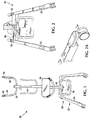
- FIG. 1 shows an exemplary embodiment of a patient lift system 20.
- Patient lift system 20 includes a frame assembly 22, generally having a U-shaped base frame 24.
- a foot rest panel 26, configured to support a patient is coupled to and supported by base frame 24, and a post 28 extends from frame assembly 22.
- a knee support 30 is coupled to a lower portion of post 28.
- a location of knee support 30 with respect to post 28 is adjustable to accommodate patients of varying height, as well as adjustable in a direction towards or a direction away from post 28.
- a swinging arm 32 is coupled to an upper portion of post 28. Swinging arm 32 is movable upwards and downwards in a vertical plane.
- an electric or hydraulic driving means 34 is operatively coupled to swinging arm 32 to facilitate movement of swinging arm 32 into a desirable position.
- Opposing arms 36 and 38 extend from opposing terminal or free ends of swinging arm 32.
- Arm 36 extends generally parallel with arm 38 with a suitable distance between arm 36 and arm 38 to accommodate a width of the patient being lifted.
- a hook 40 is coupled to each arm 36 and 38.
- Hooks 40 are configured to retain a lifting sling or belt (not shown) suspended between arm it and arm 38.
- the belt is positioned around a torso of the patient to support the patient.
- lifting slings or belts are well known in the art and will not be described in detail herein.
- the belt is positioned about the patient's body and a first strap is then coupled to a first hook 40 in a suitable manner so that the first strap is stretched.
- a second strap is fastened to the other hook 40.
- Lifting bands are then coupled in the same way. Once it is confirmed that all bands and straps are similarly stretched, the lifting action is accomplished by the lifting bands. With the straps coupled to respective hooks 40, a tension in each strap will be maintained during the lifting operation.
- a weight scale 50 is operatively coupled to patient lift system 20.
- Weight scale 50 allows a caregiver to weight a patient while the patient is standing on and supported by foot rest panel 26 or base frame 24.
- a plurality of force sensors 52 are coupled to frame assembly 22,as shown in broken lines in FIG. 2 .
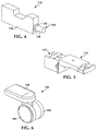
- each force sensor 52 includes a load cell, such as shown in FIG. 4 , and a castor support, as shown in FIG. 5 , operatively coupled to the load cell, as described in greater detail below.
- various force sensors can be used with weight scale 50 including, without limitation, mechanical or electrical scales such as strain gauges, transducers, and springs.
- Each force sensor 52 is configured to generate a signal indicative of a measured weight force as described herein.
- An angle sensor 54 is operatively coupled to frame assembly 22 and configured to generate a signal indicative of an angle of base frame 24 with respect to a horizontal reference plane 55 (shown schematically in FIG. 9 ).
- angle sensor 54 includes an accelerometer, such as a dual-axis accelerometer.
- Weight scale 50 also includes a control system having a controller 56, such as a printed circuit board, coupled in signal communication with each force sensor 52 and angle sensor 54.
- Controller 56 includes one or more processers 58 (shown in FIG. 8 ) configured to receive signals from and transmit signals to each force sensor 52 and angle sensor 54 to facilitate determining the actual weight force or the actual weight of the patient.
- controller 56 is configured to calibrated force sensors 52 and/or angle sensor 54 to facilitate increasing the accuracy by which weight scale 50 determines the actual weight force of the patient.
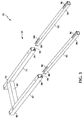
- frame assembly 22 includes base frame 24 having a first leg 62 having a first end 64 and an opposing second end 66.
- First leg 62 defines a first channel 68 between first end 64 and second end 66.
- a second leg 72 has a first end 74 and an opposing second end 76.
- Second leg 72 defines a second channel 78 between first end 74 and second end 76.
- a cross-member 80 is coupled between first leg 62 and second leg 72.
- foot rest panel 26 is coupled to base frame 24 at cross-member 80.
- Frame assembly 22 also includes a first castor support link 82 positioned within first channel 68.
- First castor support link 82 has a first end 84 that defines a first slot 86 and an opposing second end 88 that defines a second slot 90. Singularly, a second castor support link 92 is positioned within second channel 78. Second castor support link 92 has a first end 94 that defines a third slot 96 and an opposing second end 98 that defines a fourth slot 100.
- a plurality of force sensors are coupled to frame assembly 22.
- a first force sensor 102 is coupled to first end 64 of first leg 62 and first end 84 of first castor support link 82
- a second force sensor 104 is coupled to second end 66 of first leg 62 and second end 86 of first castor support link 82.
- a third force sensor 106 is coupled to first end 74 of second leg 72 and first end 94 of second castor support link 92
- a fourth force sensor 108 is coupled to second end 76 of second leg 72 and second end 98 of second castor support link 92.
- Each of first force sensor 102, second force sensor 104, third force sensor 106, and fourth force sensor 108 includes a load cell 110, such as shown in FIG. 4 , coupled to the respective leg of base frame 24 and a cooperating castor support 112, such as shown in FIG. 5 , operatively coupled to load cell 110, as described in greater detail bellow.
- load cell 110 includes a block 116 received within first channel 68 of first leg 62 of base frame 24 and positioned within first slot 86 formed at first end 84 of first castor support link 82 positioned within channel 68.
- Load cell 110 is coupled to first leg 62 at first end 64 using one or more suitable fasteners, such as bolts 118.
- a stud 120 includes a hex nut portion 122, a threaded portion 124 on one side of hex nut portion 122, and a cylindrical portion or pin 126 on the other side of hex nut portion 122.
- Threaded portion 124 is threaded into an aperture 128 defined within block 116 until hex nut portion 122 abuts block 116 and pin 126 extends longitudinally away from block 116.
- Castor support 112 as shown in FIG. 5 , is received within channel 68 and coupled to first end 84 of first castor support link 82 and to first leg 62 using one or more suitable fasteners, such as bolts 130.
- Castor support 112 defines a bore 132 which receives pin 126 with castor support 112 coupled to first leg 62 and first castor support link 82.
- Strain gauges are included in each force sensor and are coupled to respective load cell 110.
- the strain gauges operate to provide an indication of the load detected by the force sensor.
- a known voltage is applied to input leads (not shown) coupled to the stain gauges and, as pin 126 deflects due to the application of a load, a resistance in the strain gauge changes resulting in a change in an output signal generated on output leads (not shown) coupled to the strain gauges.
- the input lead and the output lead are bundled together in a cable 134, shown in FIG. 7 , that is routed between each force sensor 102, 104, 106, 108 and controller 56, which includes signal conditioning circuitry.
- a suitable castor 136 is coupled to castor support 112.
- a cover 138 is positionable about at least a portion of castor 136 to prevent or limit debris, such as dirt or dust, from attaching to the one or more rotatable castor wheels 140.
- second force sensor 104 is coupled to second end 66 of first leg 62 and second end 88 of first castor support link 82
- third force sensor 106 is coupled first end 74 of second leg 72 and first end 94 of second castor support link 92
- fourth force sensor 108 is coupled to second end 76 of second leg 72 and second end 98 of second castor support link 92.
- Each of second force sensor 104, third force sensor 106, and fourth force sensor 108 are similarly constructed as first force sensor 102 and coupled to respective portions or corners of frame assembly 22, and, as such, their assemblies are not described in detail herein.
- Each force sensor 102, 104, 106, 108 is configured to output information including, without limitation, force vector data of a measured weight force to controller 56 indicative of a portion of the weight of the patient measured by each force sensor 102, 104, 106, and 108.
- Controller 56 utilizing one or more processors 58 is configured to generate weight information including an actual weight force based at least in part on force vector data received from force sensors 102, 104, 106, and 108.
- controller 56 utilizing one or more processors 58 is configured to compensate for the force vector data received from force sensors 102, 104, 106, and 108 based on an angle information output, including an angle of base frame 24 with respect to horizontal reference plane 55, received from angle sensor 54 to generate the actual weight force.
- processor 58 More specifically, inputs from angle sensor 54 and force sensors 102, 104, 106, 108 are received by processor 58. An output from processor 58 generates weight output information. Angle sensor 54 measures the inclination angle of base frame 24 and outputs a signal corresponding to the angle to processor 58. Weight scale 50 measures the weight of patient lift system 20 and the patient and outputs a corresponding signal to processor 58. Processor 58 uses input signals from angle sensor 54 and each force sensor 102, 104, 106, 108 to compensate for error introduced in the weight scale reading when base frame 24 is inclined at an angle as described herein. Processor 58 outputs the corrected patient weight to a suitable display.
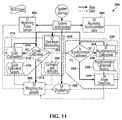
- a control system 160 for controlling operation of patient lift system 20 includes controller 56 in operational control communication with weight scale 50.
- controller 56 is coupled in signal communication with each force sensor 102, 104, 106, and 108 and angle sensor 54.
- Controller 56 includes one or more processers 58 configured to receive analog signals from each force sensor 142, 104, 106, and 108 and angle sensor, convert the analog signals to digital signals, and transmit the digital signals to a central processing unit (CPU) of controller 56 for processing the digital data to facilitate determining an actual weight force of the patient and output weight information including the actual weight force to a patient input device 162 coupled in signal communication with controller 56.
- CPU central processing unit
- Patient input device 162 includes a display 163 configured to display information received by patient input device 162 from controller 56 and/or one or more processors 58.
- patient input device 162 is configured to receive, from the user (e.g., the manufactures, a caregiver, or a patient), a selection of content to be stored on control system 160, and may include one or more of the following: display 163, a touch screen, a speaker, and a user input selection device.
- the user may select a font type, font color, font size, and volume, as well as what notifications, messages, programs, applications, and data to present and be available to the user on patient input device 162.
- Load cells 110 associated with each force sensor 102, 104, 106, and 108 generate separate analog signals that are input to a printed circuit board 164. More specifically, electrical signals continuously generated by each force sensor 102, 104, 106, and 108 are transmitted to and received by a multiplexer 166 including an analog-to-digital (A/D) converter 168. In one embodiment, one or more amplifiers (not shown) couple each force sensor 102, 104, 106, and 108 to A/D converter 168.
- A/D converter 168 the analog signals received from force sensors 102, 104, 106, and 108 are converted to respective digital signals or ADC values and transmitted to a computer or CPU, such as an ARM Cortex-M processor, shown generally at 170 using a serial interface communication protocol, such as a serial peripheral interface bus (SPI), or other suitable communication protocol, for processing.
- a serial interface communication protocol such as a serial peripheral interface bus (SPI), or other suitable communication protocol
- CPU 170 is connected to various accessories including, without limitation, memory areas, such as an EEPROM 172 configured to store calibration data including results of various calibrations to weight scale 50.
- EEPROM 172 is coupled in serial interface communication with CPU 170, such as by a serial peripheral interface bus (SPI) or an inter-integrated circuit interface (I2C) protocol.
- a joint test action group (JTAG) 174 utilized to debug the controller instructions and download instructions to CPU 170, a piezo driver 176, and a LED indicator 178 are also coupled in serial interface communication with CPU 170, such as by SPI or I2C protocol.
- An input device 180 such as a keyboard, is used to input calibration information.
- Patient input device 162 and display 163 provide a visual display of data and instructions for inputting calibration data.
- patient input device 162 and display 163 provide presentation capabilities related to, for example, text, image, audio, video, graphics, alerts, and the like. Patient input device 162 and display 163 present information ranging from low-resolution to high-resolution multimedia related not only to operation and functionality of patient lift system 20 and weight scale 50, but also to a connectivity status and functionality related to other electronic components of patient lift system 20. Data connectivity capabilities of control system 160 allow for an exchange of data between these components.
- control system 160 allows control system 160 to be connected to other sources of data and media such as a laptop, a desktop, a Motion Pictures Experts Group-1 Audio Layer 3 (MP3) player, a Motion Pictures Experts Group-4 Part 14 (MP4) player, gaming systems, or other media storage devices.
- MP3 Motion Pictures Experts Group-1 Audio Layer 3
- MP4 Motion Pictures Experts Group-4 Part 14
- FIG. 8 is merely illustrative of an exemplary control system 160 that can be used in connection with one or more embodiments of the disclosure, and is not intended to be limiting in any way. Further, peripherals or components of control system 160 known in the art may not be shown, but are operable with aspects of the disclosure. For example, a speaker, a printing component, and the like are contemplated.
- the memory areas or other computer-readable media store computer-executable components.
- the memory areas store computer-executable components for receiving data from the user, controlling patient lift system 20 and weight scale 50 based on the received data, and transmitting messages and/or notifications between controller 56 and patient input device 162.
- force sensors 102, 104, 106, 108 and/or angle sensor 54 are calibrated to facilitate accurately measuring an actual weight force g, that is, an actual weight of the patient, when an angle of inclination of base frame 24 is non-horizontal.
- the weight force g is conceivable as a sum of component vector forces including a force vector Fy perpendicular to base frame 24 and a second force vector Fx parallel to base frame 24.
- force vector Fy has a first magnitude directed at a force angle a relative to the direction of the weight forced and force vector Fx has a second magnitude that is directed perpendicular to the direction of force vector Fy.
- force angle ⁇ is a complement of the angle between vertical and a plane of base frame 24.
- Force sensors such as load cells, typically measure only forces which are applied perpendicularly to base frame 24, such as force vector Fy. Therefore, when a load cell or any other suitable force sensor is positioned to measure and indicate the force vector Fy as the weight of the patient, the measured weight of the patient is inaccurate when base frame 24 is in a non-horizontal position because the weight force g is not perpendicular to the force sensor.
- a measurement of the force angle ⁇ (and a determination of the sine of the force angle ⁇ ) is used to compensate for a measurement of the force Fx, for example, in order to arrive at an actual weight force g, that is, an actual weight of the patient, when an angle of inclination of base frame 24 is non-horizontal.
- angle sensor 54 is operatively coupled to base frame 24 to measure and output a signal indicative of the angle of base frame 24 with respect to horizontal reference plane 55.
- angle sensor 54 includes an accelerometer, such as a dual-axis accelerometer, although other angles sensors may be used.
- angle sensor 54 is mounted to printed circuit board 164 of controller 56, which is parallel to an X-Y surface of angle sensor 54. Further, printed circuit board 164 is installed on patient lift system 20 such that printed circuit board 164 is parallel to base frame 24.
- the angle a as detected by angle sensor 54 is equal to an angle of inclination of base frame 24, e.g., the angle of base frame 24 with respect to horizontal reference plane 55 about a transverse axis.
- controller 56 uses output signals from angle sensor 54 to compensate for weighing errors created when base frame 24 is aligned at a non-horizontal angle with respect to horizontal reference plane 55.
- one or more processors 58 of controller 56 are configured to calibrate angle sensor 54 based on a determination of a plurality of calibration factors, including an X direction ADC value per g (XADCperg), an X direction ADC value when g is zero (XADCat0g), a Y direction ADC value per g (YADCperg), and a Y direction ADC value when g is zero (YADC-at0g), as transmitted by A/D converter 168 to CPU 170.
- XADCperg an X direction ADC value per g
- YADCperg a Y direction ADC value per g
- YADC-at0g Y direction ADC value when g is zero
- the angle of base frame 24 with respect to horizontal reference plane 55 is based on X and Y direction ADC values and the plurality of calibration factors.
- controller 56 is configured to receive an altitude value and a latitude value inputted by the patient using patient input device 162 coupled in signal communication with controller 56.
- Patient input device 162 is configured to display on display 163 information including, without limitation, a system status, weight information, foot rest panel angle information.
- Patient input device 162 is also configured to receive patient instructions utilizing a graphical user interface or display 163, for example.
- a local or factory gravity constant (G_Loc) and a shipment destination gravity constant (G_Dest) can be retrieved from memory EEPROM 172 of controller 56 based on the altitude value and the latitude value inputted by the patient using patient input device 162.
- G_Loc local or factory gravity constant
- G_Dest shipment destination gravity constant
- patient lift system 20 is calibrated at the factory without knowledge of the shipment destination.
- one or more processors 58 are further configured to determine the angle of foot rest panel 26 with respect to frame assembly 22 based on X and Y direction ADC values and the plurality of calibration factors, determine a mounting offset of foot rest panel 26, and compensate for force vector data received from each force sensor 102, 104, 106, and 108 to determine an actual weight force of the patient.
- a method 200 for weighing a patient supported on patient lift system 20 using weight scale 50 is illustrated in FIG. 11 .
- weight scale 50 is calibrated and control system 160 is initialized 202.
- weight scale 50 is calibrated as follows.
- a total weight equals the sum of the weights read by the four force sensors.
- Equations [19]-[22] and [24]-[27] are solved to obtain values for g [1], g [2], g [ 3 ] , g [4], h [ 1 ], h [2], h [3], and h [4].
- the patient's weight is measured and set equal to y0. Thereafter, the dynamic weight of the patient, y, is measured.
- one or more processors 58 receive 204 force vector data from force sensors 102, 104, 106, 108 operatively coupled to frame assembly 22 of patient lift system 20. Further, one or more processors 58 receive 206 angle information from angle sensor 54 operatively coupled to frame assembly 22. As the patient is weighed 206, one or more processors 58 compensate for the force vector data based on the angle information to determine an actual weight force of the patient. The actual weight force of the patient is displaced 208 on display 163 of patient input device 162 coupled in signal communication with controller 56.
- weight scale 50 may be calibrated 210, including calibration of force sensors 102, 104, 106, 108 before the patient is weighed. If weight scale 50 was recently calibrated 212, the patient is weighed 206. If weight scale 50 has not been recently calibrated 214, weight scale 50 is calibrated 216, as described above, using force vector data received by one or more processors 58 from each force sensor 102, 104, 106, 108 and/or suitable calibration factors received 218 by one or more processors 58 from EEPROM 172.
- angle sensor 54 may be calibrated 220 before the patient is weighed. If angle sensor 54 was recently calibrated 222, an angle of base frame 24 with respect to horizontal reference plane 55 is detected 224 by one or more processors 58 using data received from angle sensor 54, and the patient is weighed 206. If angle sensor 54 has not been recently calibrated 224, angle sensor 54 is calibrated 226, as described above, using angle data or information received by one or more processors 58 from angle sensor 54 and/or suitable calibration factors received 228 by one or more processors 58 from EEPROM 172 to detect the angle of base frame 24 with respect to horizontal reference plane 55.
- information is received 230 by one or more processors 58 to facilitate accurately determining an actual weight force of the patient.
- information inputted 232 by the patient into patient input device 162 is received by one or more processors 58 and utilized to calibrate weight scale 50.
- the patient or caregiver inputs 234 information including a shipment destination altitude value (Dest_Alt) and a shipment destination latitude value (Dest_Lat) to facilitate determining a gravity factor (G_Factor) to facilitate accurately determining an actual weight force of the patient 28 when weighing 206 the patient.
- Dest_Alt shipment destination altitude value
- Dest_Lat shipment destination latitude value
- G_Factor gravity factor
- weight scale 50 includes a non-transitory computer-readable medium having computer-executable instructions stored thereon for execution by one or more processors to perform the method for weighing a patient supported on a patient lift system weight scale.
- an exemplary operating environment includes computer readable media including computer storage media and communication media.
- Computer storage media store information such as computer readable instructions, data structures, program modules or other data.
- Communication media typically embody computer readable instructions, data structures, program modules, or other data in a modulated data signal such as a carrier wave or other transport mechanism and include any information delivery media. Combinations of any of the above are also included within the scope of computer readable media.
- embodiments of the disclosure are operational with numerous other general purpose or special purpose computing system environments or configurations.
- Examples of well-known computing systems, environments, and/or configurations that may be suitable for use with aspects of the disclosure include, but are not limited to, mobile computing devices, personal computers, server computers, hand-held or laptop devices, multiprocessor systems, gaming consoles, microprocessor-based systems, set top boxes, programmable consumer electronics, mobile telephones, network PCs, minicomputers, mainframe computers, distributed computing environments that include any of the above systems or devices, and the like.
- Embodiments of the disclosure may be described in the general context of computer-executable instructions, such as program modules, executed by one or more computers or other devices.
- the computer-executable instructions may be organized into one or more computer-executable components or modules.
- program modules include, but are not limited to, routines, programs, objects, components, and data structures that perform particular tasks or implement particular abstract data types.
- aspects of the disclosure may be implemented with any number and organization of such components or modules. For example, aspects of the disclosure are not limited to the specific computer-executable instructions or the specific components or modules illustrated in the figures and described herein.
- Other embodiments of the disclosure may include different computer-executable instructions or components having more or less functionality than illustrated and described herein.
- aspects of the disclosure transform a general-purpose computer into a special-purpose computing device when configured to execute the instructions described herein.
Landscapes
- Health & Medical Sciences (AREA)
- Nursing (AREA)
- Life Sciences & Earth Sciences (AREA)
- Animal Behavior & Ethology (AREA)
- General Health & Medical Sciences (AREA)
- Public Health (AREA)
- Veterinary Medicine (AREA)
- Physics & Mathematics (AREA)
- General Physics & Mathematics (AREA)
- Measurement Of The Respiration, Hearing Ability, Form, And Blood Characteristics Of Living Organisms (AREA)
- Rehabilitation Tools (AREA)
- Invalid Beds And Related Equipment (AREA)
Claims (14)
- Waage für ein Patientenliftsystem, wobei die Waage eine Rahmenbaugruppe (22), eine Vielzahl Kraftsensoren (102, 104, 106, 108), die an die Rahmenbaugruppe (22) gekoppelt sind, wobei jeder Kraftsensor von der Vielzahl Kraftsensoren ausgebildet ist, um ein Signal zu erzeugen, das eine gemessene Gewichtskraft anzeigt, einen Winkelsensor (54), der betriebsfähig an die Rahmenbaugruppe (22) gekoppelt ist, wobei der Winkelsensor (54) ausgebildet ist, um ein Signal zu erzeugen, das einen Winkel der Rahmenbaugruppe (22) in Bezug zu einer horizontalen Bezugsebene anzeigt, und ein Steuergerät (56) umfasst, das in Signalverbindung mit jedem Kraftsensor (102, 104, 106, 108) und dem Winkelsensor (54) gekoppelt ist, wobei das Steuergerät einen oder mehrere Prozessoren umfasst, die ausgebildet sind, um Signale von jedem Kraftsensor (102, 104, 106, 108) und dem Winkelsensor (54) zu empfangen, um eine tatsächliche Gewichtskraft des Patienten zu bestimmen, dadurch gekennzeichnet, dass die Waage ferner eine Fußstützplatte (26), die an die Rahmenbaugruppe (22) gekoppelt ist, wobei die Fußstützplatte (26) ausgebildet ist, um einen Patienten zu unterstützen, einen Grundrahmen (24) der Rahmenbaugruppe, der einen ersten Schenkel (62), der ein erstes Ende (64) und ein entgegengesetztes zweites Ende (66) aufweist, wobei der erste Schenkel (62) einen ersten Kanal (68) zwischen dem ersten Ende (64) und dem zweiten Ende (66) definiert, und einen zweiten Schenkel (72) umfasst, der ein erstes Ende (74) und ein entgegengesetztes zweites Ende (76) aufweist, wobei der zweite Schenkel (72) einen zweiten Kanal (78) zwischen dem ersten Ende (74) und dem zweiten Ende (76) des zweiten Schenkels (72) definiert, ein erstes Laufrollen-Stützbindeglied (82), das innerhalb des ersten Kanals (68) positioniert ist, wobei das erste Laufrollen-Stützbindeglied (82) ein erstes Ende (84), das einen ersten Schlitz (86) definiert, und ein entgegengesetztes zweites Ende (88) aufweist, das einen zweiten Schlitz (90) definiert, einen ersten Kraftsensor (102) von der Vielzahl Kraftsensoren, der innerhalb des ersten Schlitzes (86) positioniert ist und am ersten Ende (64) des ersten Schenkels an den ersten Schenkel (62) gekoppelt ist, und einen zweiten Kraftsensor (104) von der Vielzahl Kraftsensoren, der innerhalb des zweiten Schlitzes (90) positioniert ist und am zweiten Ende (66) des ersten Schenkels an den ersten Schenkel (62) gekoppelt ist, und ein zweites Laufrollen-Stützbindeglied (92) umfasst, das innerhalb des zweiten Kanals (78) positioniert ist, wobei das zweite Laufrollen-Stützbindeglied (92) ein erstes Ende (94), das einen dritten Schlitz (96) definiert, und ein entgegengesetztes zweites Ende (98) aufweist, das einen vierten Schlitz (100) definiert, wobei ein dritter Kraftsensor (106) von der Vielzahl Kraftsensoren innerhalb des dritten Schlitzes (96) positioniert ist und an den zweiten Schenkel (72) am ersten Ende (74) des zweiten Schenkels gekoppelt ist, und ein vierter Kraftsensor (108) von der Vielzahl Kraftsensoren innerhalb des vierten Schlitzes (100) positioniert ist und am zweiten Ende (76) des zweiten Schenkels an den zweiten Schenkel (72) gekoppelt ist.
- Waage nach Anspruch 1, wobei der erste Kraftsensor eine Kraftmessdose (110) umfasst, wobei die Kraftmessdose (110) einen Stift (126) und eine Laufrollenstütze (112) umfasst, die an das erste Ende (64) des ersten Schenkels und das erste Ende (84) des Laufrollen-Stützbindeglieds gekoppelt ist, wobei die Laufrollenstütze (112) eine Bohrung (132) definiert, die ausgebildet ist, um den Stift (126) mit der an den ersten Schenkel (62) gekoppelten Laufrollenstütze (112) aufzunehmen.
- Waage nach Anspruch 1, wobei jeder Kraftsensor (102, 104, 106, 108) ausgebildet ist, um Kraftvektorinformationen, die die gemessene Gewichtskraft umfassen, an das Steuergerät (56) auszugeben, die einen Teil der durch jeden Kraftsensor (102, 104, 106, 108) gemessenen tatsächlichen Gewichtskraft des Patienten anzeigt.
- Waage nach Anspruch 3, wobei das Steuergerät (56) ausgebildet ist, um Gewichtsinformationen, die die tatsächliche Gewichtskraft einschließen, mindestens teilweise basierend auf von jedem Kraftsensor (102, 104, 106, 108) empfangenen Kraftvektorinformationen zu erzeugen.
- Waage nach Anspruch 4, wobei das Steuergerät (56) ausgebildet ist, um die von jedem Kraftsensor (102, 104, 106, 108) empfangenen Kraftvektorinformationen basierend auf ausgegebenen Winkelinformationen, die von dem Winkelsensor (54) empfangen werden, zu kompensieren, um die tatsächliche Gewichtskraft zu erzeugen.
- Waage nach Anspruch 1, die ferner ein Patienteneingabegerät (162) in Signalverbindung mit dem Steuergerät (56) umfasst, wobei das Patienteneingabegerät (162) eine Anzeige (163) umfasst, die ausgebildet ist, um von dem Steuergerät (56) empfangene Informationen anzuzeigen.
- Waage nach Anspruch 1, wobei die Steuereinrichtung (56) ausgebildet ist, um die Vielzahl Kraftsensoren (102, 104, 106, 108) zu kalibrieren.
- Waage nach Anspruch 1, wobei das Steuergerät (56) ausgebildet ist, um den Winkelsensor (54) zu kalibrieren.
- Waage nach Anspruch 1, wobei jeder Kraftsensor eine Kraftmessdose (110) und eine Laufrollenstütze (112) umfasst, die betriebsfähig an die Kraftmessdose (110) gekoppelt ist.
- Waage nach Anspruch 1, wobei der Winkelsensor einen Beschleunigungsmesser (54) umfasst.
- Verfahren zum Wiegen eines Patienten, der auf einem Patientenliftsystem unterstützt wird, wobei das Patientenliftsystem ein Steuergerät (56) einschließt, das einen oder mehrere Prozessoren umfasst, die betriebsfähig sind, um maschinenausführbare Befehle auszuführen, wobei das Verfahren Folgendes umfasst:Bereitstellen einer Waage des Patientenliftsystems, das einen Grundrahmen einer Rahmenbaugruppe (22), die einen ersten Schenkel (62), der ein erstes Ende (64) und ein entgegengesetztes zweites Ende (66) aufweist, wobei der erste Schenkel (64) einen ersten Kanal (68) zwischen dem ersten Ende (64) und einem zweiten Ende (66) definiert, und einen zweiten Schenkel (72) umfasst, der ein erstes Ende (64) und ein entgegengesetztes zweites Ende (66) aufweist, wobei der zweite Schenkel (72) einen zweiten Kanal (78) zwischen dem ersten Ende (64) und dem zweiten Ende (66) des zweiten Schenkels (72) definiert, ein erstes Laufrollen-Stützbindeglied (82), das innerhalb des ersten Kanals (68) positioniert ist, wobei das erste Laufrollen-Stützbindeglied (82) ein erstes Ende (64), das einen ersten Schlitz (86) definiert, und ein entgegengesetztes zweites Ende (66) aufweist, das einen zweiten Schlitz (90) definiert, einen ersten Kraftsensor von einer Vielzahl Kraftsensoren (102, 104, 106, 108), der innerhalb des ersten Schlitzes positioniert ist und am ersten Ende (64) des ersten Schenkels (62) an den ersten Schenkel (62) gekoppelt ist; einen zweiten Kraftsensor von der Vielzahl Kraftsensoren (102, 104, 106, 108), der innerhalb des zweiten Schlitzes (90) positioniert ist und am zweiten Ende (66) des ersten Schenkels (64) an den ersten Schenkel (64) gekoppelt ist; ein zweites Laufrollen-Stützbindeglied (92), das innerhalb des zweiten Kanals (78) positioniert ist, wobei das zweite Laufrollen-Stützbindeglied (92) ein erstes Ende (64), das einen dritten Schlitz (96) definiert, und ein entgegengesetztes zweites Ende (66) aufweist, das einen vierten Schlitz (100) definiert; einen dritten Kraftsensor (106) von der Vielzahl Kraftsensoren (102, 104, 106, 108), der innerhalb des dritten Schlitzes (96) positioniert ist und am ersten Ende des zweiten Schenkels (74) an den zweiten Schenkel (72) gekoppelt ist; und einen vierten Kraftsensor (108) von der Vielzahl Kraftsensoren umfasst, der innerhalb des vierten Schlitzes (100) positioniert ist und am zweiten Ende (76) des zweiten Schenkels an den zweiten Schenkel (72) gekoppelt ist,Empfangen von Kraftvektordaten von den Kraftsensoren (102, 104, 106, 108) durch den einen oder die mehreren Prozessoren;Empfangen von Winkelinformationen von einem Winkelsensor (54), der betriebsfähig an die Rahmenbaugruppe (22) gekoppelt ist, durch den einen oder die mehreren Prozessoren;Kompensieren der Kraftvektordaten basierend auf den Winkelinformationen durch den einen oder die mehreren Prozessoren;Bestimmen einer tatsächlichen Gewichtskraft des Patienten durch den einen oder die mehreren Prozessoren; undAnzeigen der tatsächlichen Gewichtskraft des Patienten auf einer Anzeige (163), die in Signalverbindung mit dem Steuergerät (56) gekoppelt ist.
- Verfahren nach Anspruch 11, das ferner das Kalibrieren der Vielzahl Kraftsensoren (102, 104, 106, 108) durch den einen oder die mehreren Prozessoren und/ oder das Kalibrieren des Winkelsensors (54) durch den einen oder die mehreren Prozessoren umfasst.
- Verfahren nach Anspruch 11, das ferner das Initialisieren des Steuergeräts (56) durch den einen oder die mehreren Prozessoren umfasst.
- Nichtflüchtiger maschinenlesbarer Datenträger, der darauf gespeichert maschinenausführbare Befehle zur Ausführung durch einen oder mehrere Prozessoren aufweist, um ein Verfahren zum Wiegen eines auf einem Patientenliftsystem unterstützten Patienten durchzuführen, wobei die Waage einen Grundrahmen einer Rahmenbaugruppe (22) umfasst, die einen ersten Schenkel (62), der ein erstes Ende (64) und ein entgegengesetztes zweites Ende (66) aufweist, wobei der erste Schenkel (64) einen ersten Kanal (68) zwischen dem ersten Ende (64) und einem zweiten Ende (66) aufweist, und einen zweiten Schenkel (72) umfasst, der ein erstes Ende (64) und ein entgegengesetztes zweites Ende (66) aufweist, wobei der zweite Schenkel (72) einen zweiten Kanal (78) zwischen dem ersten Ende (64) und dem zweiten Ende (66) des zweiten Schenkels (72) definiert, ein erstes Laufrollen-Stützbindeglied (92), das innerhalb des ersten Kanals (68) positioniert ist, wobei das erste Laufrollen-Stützbindeglied (82) ein erstes Ende (64), das einen ersten Schlitz (86) definiert, und ein entgegengesetztes zweites Ende (66) aufweist, das einen zweiten Schlitz (90) definiert, einen ersten Kraftsensor von einer Vielzahl Kraftsensoren (102, 104, 106, 108), der innerhalb des ersten Schlitzes (86) positioniert ist und am ersten Ende (64) des ersten Schenkels (62) an den ersten Schenkel (62) gekoppelt ist; einen zweiten Kraftsensor von der Vielzahl Kraftsensoren (102, 104, 106, 108), der innerhalb des zweiten Schlitzes (90) positioniert ist und am zweiten Ende (66) des ersten Schenkels (64) an den ersten Schenkel (64) gekoppelt ist; ein zweites Laufrollen-Stützbindeglied (92), das innerhalb des zweiten Kanals (78) positioniert ist, wobei das zweite Laufrollen-Stützbindeglied (92) ein erstes Ende (64), das einen dritten Schlitz (96) definiert und ein entgegengesetztes zweites Ende (66) aufweist, das einen vierten Schlitz (100) definiert; einen dritten Kraftsensor (106) von der Vielzahl Kraftsensoren (102, 104, 106, 108), der in dem dritten Schlitz (96) positioniert ist und am ersten Ende des zweiten Schenkels (74) an den zweiten Schenkel (72) gekoppelt ist; und einen vierten Kraftsensor (108) von der Vielzahl Kraftsensoren (102, 104, 106, 108) umfasst, der innerhalb des vierten Schlitzes (100) positioniert ist und am zweiten Ende (76) des zweiten Schenkels an den zweiten Schenkel (72) gekoppelt ist,
wobei das Verfahren Folgendes umfasst:Empfangen von Kraftvektordaten von der Vielzahl Kraftsensoren (102, 104, 106, 108);Empfangen von Informationen, die einen Winkel der Rahmenbaugruppe (22) in Bezug zu einer horizontalen Bezugsebene angeben, von einem Winkelsensor (54), der betriebsfähig an die Rahmenbaugruppe (22) des Patientenliftsystems gekoppelt ist;Kompensieren der Kraftvektordaten basierend auf den Informationen; undBestimmen einer tatsächlichen Gewichtskraft des Patienten.
Applications Claiming Priority (2)
| Application Number | Priority Date | Filing Date | Title |
|---|---|---|---|
| US13/488,963 US8987616B2 (en) | 2012-06-05 | 2012-06-05 | Weight scale for a patient lift system, a control system for the weight scale, and a method for weighing a patient supported on the weight scale |
| PCT/IB2013/001731 WO2013182908A2 (en) | 2012-06-05 | 2013-06-05 | Weight scale for a patient lift system, a control system for the weight scale, and a method for weighing a patient supported on the weight scale |
Publications (2)
| Publication Number | Publication Date |
|---|---|
| EP2856090A2 EP2856090A2 (de) | 2015-04-08 |
| EP2856090B1 true EP2856090B1 (de) | 2016-05-25 |
Family
ID=48783285
Family Applications (1)
| Application Number | Title | Priority Date | Filing Date |
|---|---|---|---|
| EP13774232.6A Active EP2856090B1 (de) | 2012-06-05 | 2013-06-05 | Waage für ein patientenhebesystem, steuerungssystem für die waage und verfahren zum wiegen eines patienten auf der waage |
Country Status (3)
| Country | Link |
|---|---|
| US (1) | US8987616B2 (de) |
| EP (1) | EP2856090B1 (de) |
| WO (2) | WO2013182908A2 (de) |
Cited By (1)
| Publication number | Priority date | Publication date | Assignee | Title |
|---|---|---|---|---|
| DE102020107304A1 (de) | 2020-03-17 | 2021-09-23 | Minebea Intec GmbH | Bockrolle oder Lenkrolle mit einer Wägezelle |
Families Citing this family (17)
| Publication number | Priority date | Publication date | Assignee | Title |
|---|---|---|---|---|
| US10045895B2 (en) * | 2011-08-24 | 2018-08-14 | Liko Research & Development Ab | Patient stand assist and therapy devices and methods |
| US20140020175A1 (en) * | 2012-07-12 | 2014-01-23 | Steven A. Dixon | Monitoring systems devices and methods for patient lifts |
| US9693922B2 (en) * | 2013-10-21 | 2017-07-04 | Liko Research & Development Ab | Sling bar or lift strap connector having an integrated scale with tilt compensation |
| EP3111907B1 (de) | 2015-07-01 | 2021-03-10 | Liko Research & Development AB | Personenhebevorrichtungen mit zusätzlichen detektionsfunktionen und verfahren zum betrieb davon |
| EP3111906B1 (de) * | 2015-07-01 | 2023-05-10 | Liko Research & Development AB | Personenhebevorrichtungen und verfahren zum betrieb von personenhebevorrichtungen |
| US10376434B2 (en) | 2015-07-31 | 2019-08-13 | Liko Research & Developmetn AB | Person lift devices and scale assemblies for person lift devices including accessory tracking features |
| US10314758B2 (en) | 2015-07-31 | 2019-06-11 | Allen Medical Systems, Inc. | Person support apparatus with tracking features |
| US10365150B2 (en) * | 2016-05-24 | 2019-07-30 | Ineye Technologies Llc | Travel facilitation system |
| CN110114046B (zh) | 2016-11-28 | 2021-07-13 | 威博外科公司 | 减少非期望的振动的机器人外科系统 |
| US11096852B2 (en) * | 2017-06-01 | 2021-08-24 | Liko Research & Development Ab | Systems for monitoring person lifting devices using load tension pins |
| US20180369043A1 (en) * | 2017-06-21 | 2018-12-27 | Lamin Fofana | Patient lift |
| CN107669434A (zh) * | 2017-10-20 | 2018-02-09 | 贵州信邦富顿科技有限公司 | 一种临床、远程服务两用医疗机器人及其服务方法 |
| CN112312800B (zh) * | 2018-01-15 | 2024-05-31 | 神经同步实验室有限责任公司 | 操纵杆椅子 |
| DE102018215479A1 (de) * | 2018-09-12 | 2020-03-12 | Asp Gmbh | Vorrichtung zur Unterstützung der Eigenfortbewegungsfähigkeit eines in seiner Mobilität eingeschränkten Menschen |
| DE102018215529A1 (de) * | 2018-09-12 | 2020-03-12 | Asp Gmbh | Assistent zum Stabilisieren, Mobilisieren und Sichern eines Patienten |
| SE544251C2 (en) * | 2020-07-06 | 2022-03-15 | Arjo Ip Holding Ab | Patient handling apparatus comprising a weighing arrangement |
| US12379241B2 (en) * | 2021-05-17 | 2025-08-05 | Pelstar, Llc | Tray mounting assembly for a scale |
Family Cites Families (25)
| Publication number | Priority date | Publication date | Assignee | Title |
|---|---|---|---|---|
| US3322222A (en) * | 1964-11-12 | 1967-05-30 | Baur Fritz | Compensated electromagnetic balance |
| FI47840C (fi) * | 1970-02-05 | 1974-04-10 | Datex Oy | Potilasvaaka |
| JPS6134425A (ja) * | 1984-07-27 | 1986-02-18 | Komatsu Ltd | ダンプトラツクの積載重量測定方法 |
| CA1211954A (en) * | 1985-08-06 | 1986-09-30 | Michael J. Karpa | Device and procedure for testing heavy capacity scales |
| US4869266A (en) * | 1985-12-31 | 1989-09-26 | Stonecrest Systems, Inc. | Patient monitoring unit for surgical use |
| US5802640A (en) * | 1992-04-03 | 1998-09-08 | Hill-Rom, Inc. | Patient care system |
| US5209313A (en) * | 1991-03-28 | 1993-05-11 | Teledyne Industries, Inc. | Lift weighing |
| US5646376A (en) * | 1994-06-09 | 1997-07-08 | Intercomp Company | Aircraft weighing scale with improved base, platform and load cell mounting assembly |
| US5823278A (en) * | 1994-10-13 | 1998-10-20 | Future Systems, Inc. | Caster mounted weighing system |
| US5831221A (en) * | 1994-10-13 | 1998-11-03 | Future Sysems, Inc. | Caster mounted weighing system |
| US5837946A (en) * | 1995-06-16 | 1998-11-17 | Weigh-Tronix, Inc. | Force sensitive scale and dual load sensor cell for use therewith |
| US20040221388A1 (en) * | 1995-09-13 | 2004-11-11 | Votel Thomas W. | Patient moving apparatus having sheet gripper with user input |
| US5737781A (en) * | 1995-09-13 | 1998-04-14 | Ergodyne Corporation | Patient transfer system |
| US5892180A (en) * | 1997-02-03 | 1999-04-06 | Medcare Products, L.C. | Patient hoist and scale |
| GB9902859D0 (en) * | 1999-02-10 | 1999-03-31 | Arjo Ltd | Invalid hoists |
| US6924441B1 (en) * | 1999-09-29 | 2005-08-02 | Hill-Rom Services, Inc. | Load cell apparatus |
| US6639157B2 (en) * | 2000-08-22 | 2003-10-28 | Louis E. Sternberg | Portable attachable weighing system |
| US6806430B2 (en) * | 2001-04-23 | 2004-10-19 | Ez Way, Inc. | Patient lift and scale |
| JP2005528139A (ja) * | 2002-03-18 | 2005-09-22 | ヒル−ロム サービシーズ,インコーポレイティド | 病院ベッド制御装置 |
| US7022921B2 (en) * | 2003-05-28 | 2006-04-04 | Sr Instruments, Inc. | Electronic scale assembly having incorporated spreader arm |
| US6964070B2 (en) * | 2003-11-12 | 2005-11-15 | Gary Lee Hawk | Patient lifting apparatus |
| US7176391B2 (en) * | 2004-09-13 | 2007-02-13 | Hill-Rom Services, Inc. | Load cell to frame interface for hospital bed |
| DE102006059261B4 (de) * | 2006-12-15 | 2010-09-09 | Sartorius Ag | Elektronische Waage mit einem Neigungsmesser und zugehöriges Verfahren zur Signalauswertung |
| DE102009011272A1 (de) | 2009-03-05 | 2010-09-23 | Hottinger Baldwin Messtechnik Gmbh | Verfahren zum Wägen einer Last und Verfahren zur Berichtigung einer Gewichtskraft einer Last sowie Vorrichtung zum Wägen einer Last |
| DE102010014153A1 (de) | 2010-04-07 | 2011-10-13 | Hottinger Baldwin Messtechnik Gmbh | Mobiles Patientenhebegerät mit einer Wägevorrichtung |
-
2012
- 2012-06-05 US US13/488,963 patent/US8987616B2/en active Active
-
2013
- 2013-06-05 EP EP13774232.6A patent/EP2856090B1/de active Active
- 2013-06-05 WO PCT/IB2013/001731 patent/WO2013182908A2/en not_active Ceased
- 2013-06-06 WO PCT/IB2013/001167 patent/WO2013182886A2/en not_active Ceased
Cited By (1)
| Publication number | Priority date | Publication date | Assignee | Title |
|---|---|---|---|---|
| DE102020107304A1 (de) | 2020-03-17 | 2021-09-23 | Minebea Intec GmbH | Bockrolle oder Lenkrolle mit einer Wägezelle |
Also Published As
| Publication number | Publication date |
|---|---|
| WO2013182886A2 (en) | 2013-12-12 |
| WO2013182886A3 (en) | 2014-04-17 |
| US20130319775A1 (en) | 2013-12-05 |
| WO2013182908A3 (en) | 2014-12-11 |
| EP2856090A2 (de) | 2015-04-08 |
| US8987616B2 (en) | 2015-03-24 |
| WO2013182908A2 (en) | 2013-12-12 |
Similar Documents
| Publication | Publication Date | Title |
|---|---|---|
| EP2856090B1 (de) | Waage für ein patientenhebesystem, steuerungssystem für die waage und verfahren zum wiegen eines patienten auf der waage | |
| US10765936B2 (en) | Force measurement system | |
| US20200408625A1 (en) | Force Measurement System | |
| CN102778287A (zh) | 一种可倾斜称重电子秤的控制系统和控制方法 | |
| JPS5916646B2 (ja) | フドウビ−ムツキトウモ−メントジユウリヨウケイ | |
| CN101413840A (zh) | 一种物体质心测量装置与方法 | |
| JP2010078439A (ja) | 電子重量計および傾斜検知方法 | |
| CN104884913A (zh) | 具有补偿由于未对准误差的装置的称重传感器 | |
| CN103038121A (zh) | 手动起重搬运车 | |
| CN202853726U (zh) | 一种可倾斜称重电子秤的控制系统 | |
| US12332109B2 (en) | Method for configuring a calibration mechanism and force sensor thereof | |
| US8921717B2 (en) | Weight magnitude and weight position indication systems and methods | |
| JP2005148069A (ja) | 多点式秤 | |
| JP5355077B2 (ja) | 秤量装置、とくに多列秤量装置 | |
| US12066320B2 (en) | Calibration system and method | |
| US20090005709A1 (en) | Range of motion measurement device | |
| US9429459B2 (en) | System and method for measuring a mass of fuel within a variable geometry container | |
| CN1250945C (zh) | 电子天平 | |
| CN107702773A (zh) | 负重测量装置、方法及负重设备 | |
| RU201037U1 (ru) | Устройство для взвешивания и определения координат центра масс взвешиваемого объекта | |
| CN213397322U (zh) | 称重传感器及包含其的称重勺 | |
| WO2011056865A1 (en) | Improvements relating to load cells | |
| JP2008256481A (ja) | 計量装置の補正方法 | |
| JP3621188B2 (ja) | 質量測定装置 | |
| JPH067053B2 (ja) | 姿勢センサ |
Legal Events
| Date | Code | Title | Description |
|---|---|---|---|
| PUAI | Public reference made under article 153(3) epc to a published international application that has entered the european phase |
Free format text: ORIGINAL CODE: 0009012 |
|
| 17P | Request for examination filed |
Effective date: 20141223 |
|
| AK | Designated contracting states |
Kind code of ref document: A2 Designated state(s): AL AT BE BG CH CY CZ DE DK EE ES FI FR GB GR HR HU IE IS IT LI LT LU LV MC MK MT NL NO PL PT RO RS SE SI SK SM TR |
|
| AX | Request for extension of the european patent |
Extension state: BA ME |
|
| RAP1 | Party data changed (applicant data changed or rights of an application transferred) |
Owner name: LIKO RESEARCH & DEVELOPMENT AB |
|
| DAX | Request for extension of the european patent (deleted) | ||
| RIC1 | Information provided on ipc code assigned before grant |
Ipc: G01G 23/00 20060101ALI20151023BHEP Ipc: G01G 19/44 20060101AFI20151023BHEP Ipc: A61G 7/10 20060101ALI20151023BHEP Ipc: G01G 19/52 20060101ALI20151023BHEP |
|
| GRAP | Despatch of communication of intention to grant a patent |
Free format text: ORIGINAL CODE: EPIDOSNIGR1 |
|
| INTG | Intention to grant announced |
Effective date: 20151216 |
|
| GRAS | Grant fee paid |
Free format text: ORIGINAL CODE: EPIDOSNIGR3 |
|
| GRAA | (expected) grant |
Free format text: ORIGINAL CODE: 0009210 |
|
| REG | Reference to a national code |
Ref country code: FR Ref legal event code: PLFP Year of fee payment: 4 |
|
| AK | Designated contracting states |
Kind code of ref document: B1 Designated state(s): AL AT BE BG CH CY CZ DE DK EE ES FI FR GB GR HR HU IE IS IT LI LT LU LV MC MK MT NL NO PL PT RO RS SE SI SK SM TR |
|
| REG | Reference to a national code |
Ref country code: GB Ref legal event code: FG4D |
|
| REG | Reference to a national code |
Ref country code: CH Ref legal event code: EP |
|
| REG | Reference to a national code |
Ref country code: IE Ref legal event code: FG4D Ref country code: AT Ref legal event code: REF Ref document number: 802693 Country of ref document: AT Kind code of ref document: T Effective date: 20160615 |
|
| REG | Reference to a national code |
Ref country code: DE Ref legal event code: R096 Ref document number: 602013008082 Country of ref document: DE |
|
| REG | Reference to a national code |
Ref country code: LT Ref legal event code: MG4D |
|
| REG | Reference to a national code |
Ref country code: NL Ref legal event code: MP Effective date: 20160525 |
|
| PG25 | Lapsed in a contracting state [announced via postgrant information from national office to epo] |
Ref country code: NL Free format text: LAPSE BECAUSE OF FAILURE TO SUBMIT A TRANSLATION OF THE DESCRIPTION OR TO PAY THE FEE WITHIN THE PRESCRIBED TIME-LIMIT Effective date: 20160525 Ref country code: FI Free format text: LAPSE BECAUSE OF FAILURE TO SUBMIT A TRANSLATION OF THE DESCRIPTION OR TO PAY THE FEE WITHIN THE PRESCRIBED TIME-LIMIT Effective date: 20160525 Ref country code: NO Free format text: LAPSE BECAUSE OF FAILURE TO SUBMIT A TRANSLATION OF THE DESCRIPTION OR TO PAY THE FEE WITHIN THE PRESCRIBED TIME-LIMIT Effective date: 20160825 Ref country code: LT Free format text: LAPSE BECAUSE OF FAILURE TO SUBMIT A TRANSLATION OF THE DESCRIPTION OR TO PAY THE FEE WITHIN THE PRESCRIBED TIME-LIMIT Effective date: 20160525 |
|
| REG | Reference to a national code |
Ref country code: AT Ref legal event code: MK05 Ref document number: 802693 Country of ref document: AT Kind code of ref document: T Effective date: 20160525 |
|
| PG25 | Lapsed in a contracting state [announced via postgrant information from national office to epo] |
Ref country code: GR Free format text: LAPSE BECAUSE OF FAILURE TO SUBMIT A TRANSLATION OF THE DESCRIPTION OR TO PAY THE FEE WITHIN THE PRESCRIBED TIME-LIMIT Effective date: 20160826 Ref country code: PT Free format text: LAPSE BECAUSE OF FAILURE TO SUBMIT A TRANSLATION OF THE DESCRIPTION OR TO PAY THE FEE WITHIN THE PRESCRIBED TIME-LIMIT Effective date: 20160926 Ref country code: SE Free format text: LAPSE BECAUSE OF FAILURE TO SUBMIT A TRANSLATION OF THE DESCRIPTION OR TO PAY THE FEE WITHIN THE PRESCRIBED TIME-LIMIT Effective date: 20160525 Ref country code: LV Free format text: LAPSE BECAUSE OF FAILURE TO SUBMIT A TRANSLATION OF THE DESCRIPTION OR TO PAY THE FEE WITHIN THE PRESCRIBED TIME-LIMIT Effective date: 20160525 Ref country code: RS Free format text: LAPSE BECAUSE OF FAILURE TO SUBMIT A TRANSLATION OF THE DESCRIPTION OR TO PAY THE FEE WITHIN THE PRESCRIBED TIME-LIMIT Effective date: 20160525 Ref country code: ES Free format text: LAPSE BECAUSE OF FAILURE TO SUBMIT A TRANSLATION OF THE DESCRIPTION OR TO PAY THE FEE WITHIN THE PRESCRIBED TIME-LIMIT Effective date: 20160525 |
|
| PG25 | Lapsed in a contracting state [announced via postgrant information from national office to epo] |
Ref country code: IT Free format text: LAPSE BECAUSE OF FAILURE TO SUBMIT A TRANSLATION OF THE DESCRIPTION OR TO PAY THE FEE WITHIN THE PRESCRIBED TIME-LIMIT Effective date: 20160525 Ref country code: BE Free format text: LAPSE BECAUSE OF NON-PAYMENT OF DUE FEES Effective date: 20160630 |
|
| PG25 | Lapsed in a contracting state [announced via postgrant information from national office to epo] |
Ref country code: RO Free format text: LAPSE BECAUSE OF FAILURE TO SUBMIT A TRANSLATION OF THE DESCRIPTION OR TO PAY THE FEE WITHIN THE PRESCRIBED TIME-LIMIT Effective date: 20160525 Ref country code: EE Free format text: LAPSE BECAUSE OF FAILURE TO SUBMIT A TRANSLATION OF THE DESCRIPTION OR TO PAY THE FEE WITHIN THE PRESCRIBED TIME-LIMIT Effective date: 20160525 Ref country code: SK Free format text: LAPSE BECAUSE OF FAILURE TO SUBMIT A TRANSLATION OF THE DESCRIPTION OR TO PAY THE FEE WITHIN THE PRESCRIBED TIME-LIMIT Effective date: 20160525 Ref country code: DK Free format text: LAPSE BECAUSE OF FAILURE TO SUBMIT A TRANSLATION OF THE DESCRIPTION OR TO PAY THE FEE WITHIN THE PRESCRIBED TIME-LIMIT Effective date: 20160525 Ref country code: CZ Free format text: LAPSE BECAUSE OF FAILURE TO SUBMIT A TRANSLATION OF THE DESCRIPTION OR TO PAY THE FEE WITHIN THE PRESCRIBED TIME-LIMIT Effective date: 20160525 |
|
| REG | Reference to a national code |
Ref country code: CH Ref legal event code: PL |
|
| PG25 | Lapsed in a contracting state [announced via postgrant information from national office to epo] |
Ref country code: BE Free format text: LAPSE BECAUSE OF FAILURE TO SUBMIT A TRANSLATION OF THE DESCRIPTION OR TO PAY THE FEE WITHIN THE PRESCRIBED TIME-LIMIT Effective date: 20160525 Ref country code: AT Free format text: LAPSE BECAUSE OF FAILURE TO SUBMIT A TRANSLATION OF THE DESCRIPTION OR TO PAY THE FEE WITHIN THE PRESCRIBED TIME-LIMIT Effective date: 20160525 Ref country code: SM Free format text: LAPSE BECAUSE OF FAILURE TO SUBMIT A TRANSLATION OF THE DESCRIPTION OR TO PAY THE FEE WITHIN THE PRESCRIBED TIME-LIMIT Effective date: 20160525 Ref country code: PL Free format text: LAPSE BECAUSE OF FAILURE TO SUBMIT A TRANSLATION OF THE DESCRIPTION OR TO PAY THE FEE WITHIN THE PRESCRIBED TIME-LIMIT Effective date: 20160525 |
|
| REG | Reference to a national code |
Ref country code: DE Ref legal event code: R097 Ref document number: 602013008082 Country of ref document: DE |
|
| REG | Reference to a national code |
Ref country code: IE Ref legal event code: MM4A |
|
| PG25 | Lapsed in a contracting state [announced via postgrant information from national office to epo] |
Ref country code: MC Free format text: LAPSE BECAUSE OF FAILURE TO SUBMIT A TRANSLATION OF THE DESCRIPTION OR TO PAY THE FEE WITHIN THE PRESCRIBED TIME-LIMIT Effective date: 20160525 |
|
| PLBE | No opposition filed within time limit |
Free format text: ORIGINAL CODE: 0009261 |
|
| STAA | Information on the status of an ep patent application or granted ep patent |
Free format text: STATUS: NO OPPOSITION FILED WITHIN TIME LIMIT |
|
| PG25 | Lapsed in a contracting state [announced via postgrant information from national office to epo] |
Ref country code: LI Free format text: LAPSE BECAUSE OF NON-PAYMENT OF DUE FEES Effective date: 20160630 Ref country code: CH Free format text: LAPSE BECAUSE OF NON-PAYMENT OF DUE FEES Effective date: 20160630 |
|
| 26N | No opposition filed |
Effective date: 20170228 |
|
| REG | Reference to a national code |
Ref country code: FR Ref legal event code: PLFP Year of fee payment: 5 |
|
| PG25 | Lapsed in a contracting state [announced via postgrant information from national office to epo] |
Ref country code: IE Free format text: LAPSE BECAUSE OF NON-PAYMENT OF DUE FEES Effective date: 20160605 Ref country code: SI Free format text: LAPSE BECAUSE OF FAILURE TO SUBMIT A TRANSLATION OF THE DESCRIPTION OR TO PAY THE FEE WITHIN THE PRESCRIBED TIME-LIMIT Effective date: 20160525 |
|
| REG | Reference to a national code |
Ref country code: FR Ref legal event code: PLFP Year of fee payment: 6 |
|
| PG25 | Lapsed in a contracting state [announced via postgrant information from national office to epo] |
Ref country code: HU Free format text: LAPSE BECAUSE OF FAILURE TO SUBMIT A TRANSLATION OF THE DESCRIPTION OR TO PAY THE FEE WITHIN THE PRESCRIBED TIME-LIMIT; INVALID AB INITIO Effective date: 20130605 |
|
| PG25 | Lapsed in a contracting state [announced via postgrant information from national office to epo] |
Ref country code: LU Free format text: LAPSE BECAUSE OF NON-PAYMENT OF DUE FEES Effective date: 20160605 Ref country code: MK Free format text: LAPSE BECAUSE OF FAILURE TO SUBMIT A TRANSLATION OF THE DESCRIPTION OR TO PAY THE FEE WITHIN THE PRESCRIBED TIME-LIMIT Effective date: 20160525 Ref country code: MT Free format text: LAPSE BECAUSE OF NON-PAYMENT OF DUE FEES Effective date: 20160630 Ref country code: IS Free format text: LAPSE BECAUSE OF FAILURE TO SUBMIT A TRANSLATION OF THE DESCRIPTION OR TO PAY THE FEE WITHIN THE PRESCRIBED TIME-LIMIT Effective date: 20160525 Ref country code: HR Free format text: LAPSE BECAUSE OF FAILURE TO SUBMIT A TRANSLATION OF THE DESCRIPTION OR TO PAY THE FEE WITHIN THE PRESCRIBED TIME-LIMIT Effective date: 20160525 Ref country code: CY Free format text: LAPSE BECAUSE OF FAILURE TO SUBMIT A TRANSLATION OF THE DESCRIPTION OR TO PAY THE FEE WITHIN THE PRESCRIBED TIME-LIMIT Effective date: 20160525 |
|
| PG25 | Lapsed in a contracting state [announced via postgrant information from national office to epo] |
Ref country code: BG Free format text: LAPSE BECAUSE OF FAILURE TO SUBMIT A TRANSLATION OF THE DESCRIPTION OR TO PAY THE FEE WITHIN THE PRESCRIBED TIME-LIMIT Effective date: 20160525 |
|
| PG25 | Lapsed in a contracting state [announced via postgrant information from national office to epo] |
Ref country code: AL Free format text: LAPSE BECAUSE OF FAILURE TO SUBMIT A TRANSLATION OF THE DESCRIPTION OR TO PAY THE FEE WITHIN THE PRESCRIBED TIME-LIMIT Effective date: 20160525 Ref country code: TR Free format text: LAPSE BECAUSE OF FAILURE TO SUBMIT A TRANSLATION OF THE DESCRIPTION OR TO PAY THE FEE WITHIN THE PRESCRIBED TIME-LIMIT Effective date: 20160525 |
|
| REG | Reference to a national code |
Ref country code: DE Ref legal event code: R082 Ref document number: 602013008082 Country of ref document: DE Representative=s name: MAIWALD GMBH, DE |
|
| PGFP | Annual fee paid to national office [announced via postgrant information from national office to epo] |
Ref country code: DE Payment date: 20250520 Year of fee payment: 13 |
|
| PGFP | Annual fee paid to national office [announced via postgrant information from national office to epo] |
Ref country code: GB Payment date: 20250520 Year of fee payment: 13 |
|
| PGFP | Annual fee paid to national office [announced via postgrant information from national office to epo] |
Ref country code: FR Payment date: 20250521 Year of fee payment: 13 |