EP4175541B1 - Vorrichtung zum sammeln von gasförmigen atemproben, und sammelverfahren mittels der vorrichtung - Google Patents
Vorrichtung zum sammeln von gasförmigen atemproben, und sammelverfahren mittels der vorrichtung Download PDFInfo
- Publication number
- EP4175541B1 EP4175541B1 EP21737670.6A EP21737670A EP4175541B1 EP 4175541 B1 EP4175541 B1 EP 4175541B1 EP 21737670 A EP21737670 A EP 21737670A EP 4175541 B1 EP4175541 B1 EP 4175541B1
- Authority
- EP
- European Patent Office
- Prior art keywords
- sampling
- oral cavity
- along
- internal
- longitudinal axis
- Prior art date
- Legal status (The legal status is an assumption and is not a legal conclusion. Google has not performed a legal analysis and makes no representation as to the accuracy of the status listed.)
- Active
Links
Images

Classifications
-
- A—HUMAN NECESSITIES
- A61—MEDICAL OR VETERINARY SCIENCE; HYGIENE
- A61B—DIAGNOSIS; SURGERY; IDENTIFICATION
- A61B5/00—Measuring for diagnostic purposes; Identification of persons
- A61B5/08—Measuring devices for evaluating the respiratory organs
- A61B5/097—Devices for facilitating collection of breath or for directing breath into or through measuring devices
-
- A—HUMAN NECESSITIES
- A61—MEDICAL OR VETERINARY SCIENCE; HYGIENE
- A61B—DIAGNOSIS; SURGERY; IDENTIFICATION
- A61B5/00—Measuring for diagnostic purposes; Identification of persons
- A61B5/08—Measuring devices for evaluating the respiratory organs
- A61B5/082—Evaluation by breath analysis, e.g. determination of the chemical composition of exhaled breath
-
- A—HUMAN NECESSITIES
- A61—MEDICAL OR VETERINARY SCIENCE; HYGIENE
- A61B—DIAGNOSIS; SURGERY; IDENTIFICATION
- A61B5/00—Measuring for diagnostic purposes; Identification of persons
- A61B5/68—Arrangements of detecting, measuring or recording means, e.g. sensors, in relation to patient
- A61B5/6801—Arrangements of detecting, measuring or recording means, e.g. sensors, in relation to patient specially adapted to be attached to or worn on the body surface
- A61B5/6813—Specially adapted to be attached to a specific body part
- A61B5/6814—Head
- A61B5/682—Mouth, e.g., oral cavity; tongue; Lips; Teeth
-
- G—PHYSICS
- G01—MEASURING; TESTING
- G01N—INVESTIGATING OR ANALYSING MATERIALS BY DETERMINING THEIR CHEMICAL OR PHYSICAL PROPERTIES
- G01N33/00—Investigating or analysing materials by specific methods not covered by groups G01N1/00 - G01N31/00
- G01N33/48—Biological material, e.g. blood, urine; Haemocytometers
- G01N33/483—Physical analysis of biological material
- G01N33/497—Physical analysis of biological material of gaseous biological material, e.g. breath
-
- A—HUMAN NECESSITIES
- A61—MEDICAL OR VETERINARY SCIENCE; HYGIENE
- A61B—DIAGNOSIS; SURGERY; IDENTIFICATION
- A61B2560/00—Constructional details of operational features of apparatus; Accessories for medical measuring apparatus
- A61B2560/04—Constructional details of apparatus
- A61B2560/0406—Constructional details of apparatus specially shaped apparatus housings
- A61B2560/0425—Ergonomically shaped housings
-
- A—HUMAN NECESSITIES
- A61—MEDICAL OR VETERINARY SCIENCE; HYGIENE
- A61B—DIAGNOSIS; SURGERY; IDENTIFICATION
- A61B2562/00—Details of sensors; Constructional details of sensor housings or probes; Accessories for sensors
- A61B2562/16—Details of sensor housings or probes; Details of structural supports for sensors
Definitions
- the field of the invention is that of taking a gaseous breath sample which may contain compounds of interest to be characterized, in particular from a human subject.
- the invention relates more particularly to a sampling device comprising a tip with a retention tab, this tab being intended to be introduced into the oral cavity of a user for the collection of a gaseous sample of his breath. It finds application in particular in the characterization of compounds of interest present in the gas sample taken, for example by means of an electronic nose using surface plasmon resonance imaging technology.
- the document EP2906945 describes a device for collecting a breath sample from a subject, to detect and characterize the presence of target compounds (e.g. ammonia) present in this gaseous sample.
- target compounds e.g. ammonia
- Such breath sampling devices make it possible to provide information derived from the analysis of a breath sample and allow, for example, the identification and quantification of the microorganisms present in the subject's mouth.
- These devices can also make it possible to detect and monitor the presence of a particular substance in the subject's breath.
- the aforementioned document indicates that the device includes a breath sampling interface which can consist of a mask or a tube.
- sampling interfaces such as breath sampling mouthpieces inserted into the subject's mouth.
- An indirect sample can also be carried out using a syringe activated by suction in the subject's mouth, then by transferring the sample taken in the syringe to a breath sampling device which carries out the analysis.
- breath sampling mouthpieces generally require strict implementation which depends on the know-how of a trained practitioner.
- the analysis results are strongly dependent on the correct execution of the process sampling.
- the samples are then not very reproducible from one person to another. They may also be vulnerable to disturbances inherent to the sampling conditions, and in particular to the physicochemical conditions relating to the oral cavity of the subject, which can lead to measurement noise degrading the quality of the sampling and therefore the characterization of the target compounds.
- oropharyngeal tips allowing gas measurements to be carried out such as the CO 2 level in the inspired and expired air of a patient then under anesthesia. These tips have a main opening allowing the patient to breathe during the measurement. These tips are described in particular in the documents WO2013/189763A1 And CN2728435 . However, they are not suitable for taking a patient's breath sample, particularly due to the main opening.
- the invention aims to remedy at least partly the drawbacks of the prior art, and more particularly to propose a sampling device with a tip intended to be inserted at least partially into an oral cavity to take a gaseous sample of breath.
- the sampling device according to the invention makes it possible to improve the characteristics of the sampling, for example in terms of reproducibility and/or in terms of measurement noise.
- the present invention is defined by the appended claims 1-13.
- the tip comprises a first so-called contention tongue, intended to come into contact with the user's tongue, formed of a thin plate oriented orthogonally to the vertical axis and extending from of the internal face and the side of the lower surface of the base along the longitudinal axis A L over a first predefined length L lc .
- the sampling device comprises a removable sampling pipe, intended to be connected to the analysis device and capable of being removed from the tip, passing through the internal conduit, and extending along the longitudinal axis A L at a distance and opposite the retention tab over a distance D less than or equal to the first length L lc , so that the retention tab prevents any contact of the tongue with the sampling pipe.
- the sampling device may include a second so-called protective tab, formed of a thin place oriented orthogonally to the vertical axis and extending from the internal face and the side of the upper surface of the base following the longitudinal axis A L over a first predefined length L lp greater than or equal to the distance D at a distance from the sampling pipe, and arranged opposite the retaining tab along the vertical axis.
- a second so-called protective tab formed of a thin place oriented orthogonally to the vertical axis and extending from the internal face and the side of the upper surface of the base following the longitudinal axis A L over a first predefined length L lp greater than or equal to the distance D at a distance from the sampling pipe, and arranged opposite the retaining tab along the vertical axis.
- the restraining tab and the protective tab may have identical shapes and extend symmetrically on either side of the longitudinal axis A L.
- the sampling device may include a stop placed on the positioning base, intended to be brought into contact with an entrance to the oral cavity.
- the stop can be formed by a collar projecting from the positioning base.
- the sampling device may include a gripping appendage extending in the extension of the positioning base along the longitudinal axis A L , the gripping appendage comprising the external face.
- the positioning base may have a cylindrical shape, defining two contact surfaces, curved and opposite each other along an axis orthogonal to the longitudinal axis A L.
- the sampling device may include a tubular rim projecting vis-à-vis the positioning base along the longitudinal axis A L.
- the sampling device may include a plurality of interior conduits each receiving a sampling pipe.
- the invention also relates to an analysis system, comprising a sampling device according to any of the preceding characteristics, and an analysis device connected to the sampling pipe.
- the analysis device may comprise a measuring chamber intended to receive the target compounds contained in the gas sample, in which is located a plurality of distinct sensitive sites each comprising receptors capable of interacting with the target compounds, the device for analysis comprising a surface plasmon resonance imaging detector, or comprising a plurality of distinct electromechanical resonators each forming a sensitive site.
- the invention also relates to a sampling method using the sampling device according to any of the preceding characteristics, in which the tip is partially introduced into the oral cavity of the user for the purpose of taking a breath sample. , the retention tab being placed in contact with the subject's tongue. Furthermore, preferably, the user breathes through the nose when collecting the gaseous breath sample, or holds his breath.
- the invention relates to a device for collecting a gaseous breath sample which may contain target compounds to be characterized.
- This sampling device comprises a tip with a retaining tab and a removable sampling pipe intended to be connected to a device for analyzing the target compounds.
- the tip is suitable for closing the user's oral cavity.
- the compounds of interest are elements contained in the gas sample and intended to be characterized by the analysis device. They can be, by way of illustration, bacteria, viruses, proteins, lipids, volatile organic molecules, inorganic compounds, among others. It can also be sulfur compounds present in the oral cavity of a subject (human, animal, etc.).
- the analysis device can be called an 'electronic nose'. It can use surface plasmon resonance (SFR) measurement technology as described for example in the publication of Brenet et al. entitled Highly-Selective Optoelectronic Nose based on Surface Plasmon resonance Imaging for Sensing Gas Phase Volatile Organic Compounds, Anal. Chem. 2018, 90, 16, 9879-9887 .
- SFR surface plasmon resonance
- other measurement technologies can be implemented, such as measurement by electromagnetic resonators of the MEMS or NEMS type (for example, described in the document EP3184485 ). More broadly, the measuring device can be of the resistive, piezoelectric, mechanical, acoustic or optical type.
- the tip of the sampling device is intended to be partially introduced into the oral cavity, and is adapted to seal the oral cavity of the user. It includes a retention tab intended to come into contact with or opposite a surface which delimits the oral cavity, that is to say the interior of the oral cavity.
- a retention tab intended to come into contact with or opposite a surface which delimits the oral cavity, that is to say the interior of the oral cavity.
- the length of the retaining tab is greater than or equal to the distance along which the sampling pipe extends projecting vis-à-vis an internal face of the end piece.
- the retaining tab prevents a surface which delimits the oral cavity from moving and disrupting the collection of the gas sample by the sampling pipe.
- this surface is notably the tongue of the subject (human person, or animal), which, by moving, during sampling, can modify the local physicochemical conditions in the oral cavity (presence of drops of saliva, humidity level more high, mechanical interaction with the pipe, etc.).
- FIG. 1 is a schematic side view of an analysis system 1 comprising a sampling device 2 according to one embodiment, fluidly connected to an analysis device 3.
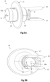
- the figures 2 , 3A and 3B illustrate the tip 10 in different views.
- the sample is taken from the oral cavity of a human person. This involves taking a gaseous sample of the breath, this gaseous sample comprising target sulfur compounds to be characterized, located at a non-zero distance from the entrance to the oral cavity.
- the sampling device 2 thus comprises a sampling tip 10 intended to be partly introduced into the oral cavity, which comprises a first so-called containment tongue 15, and a removable sampling pipe 4 which extends opposite the tongue of restraint 15 and is intended to be connected to the analysis device 3.
- the two external faces 10a and internal 10b are here parallel to each other, but they can be inclined relative to each other.
- the external face 10a here comprises two external orifices 11, and the internal face 10b comprises two internal orifices 12, two internal conduits 13 connecting an external orifice 11 to an internal orifice 12.
- the faces 10a, 10b may comprise a single orifice external and a single internal orifice, or a plurality of orifices.
- An internal conduit 13 tightly connects the external 11 and internal 12 orifices.
- the structure of the mouthpiece 10 is made of a material which is preferably rigid and chemically inert.
- the mouthpiece 10 includes a positioning base 14, which here forms part of the structure of the mouthpiece.
- the base 14 has the internal face 10b and is intended to be at least partly introduced into the cavity oral. In this breath sampling application, it is intended to be held in the oral cavity by a clamping force applied by the subject's teeth on the base 14 along the vertical axis. More precisely, it has a lower surface 14a and an upper surface 14b, intended to be in contact with the teeth of the user who then ensures the maintenance of the mouthpiece 10 in the oral cavity.
- the surfaces 14a and 14b are opposite each other along the vertical axis (axis of tightening by the user's teeth) and are located on either side of the internal orifice 12.
- the mouthpiece 10 is adapted to seal the entrance to the oral cavity, even if it is not necessarily a watertight seal.
- the base 14 has transverse dimensions (in a plane orthogonal to the axis A L ) at most equal to the dimensions of the entrance to the oral cavity.
- the collar 17 extends from the base 14 over its entire circumference and has dimensions greater than the entrance to the oral cavity.
- the mouthpiece 10 preferably comprises a gripping appendage 16, allowing a practitioner or the subject himself to manipulate the mouthpiece 10 to partially introduce it into the oral cavity.
- the appendix 16 has the external face 10a and is intended not to be introduced into the oral cavity.
- the appendix 16 and the base 14 are two parts made in one piece of the same structure. Alternatively, it may be two parts assembled together but removable. They each have the shape of a cylinder with an oval or elliptical base, arranged in the extension of one and the other along the longitudinal axis A L of the mouthpiece.
- the cylindrical base may have other shapes, such as for example a polygonal shape, for example rectangular.
- the mouthpiece 10 includes a first so-called retention tab 15.
- the retaining tab 15 is a thin plate made of a rigid material, preferably identical to that of the structure of the end piece 10, which has a length along the longitudinal axis A L greater than its thickness. It is oriented substantially orthogonal to the vertical axis, therefore horizontally and not vertically. In other words, its width is substantially orthogonal to the vertical axis.
- sample 4 It has an exterior surface which is intended to come into contact with or opposite a surface which delimits the oral cavity, and an interior surface, opposite the exterior surface, which is intended to be opposite the pipe.
- sample 4. It extends over at least part of the edge of the internal face 10b. It extends from the internal face 10b along the longitudinal axis A L over a predefined length L lc . In this example, it is positioned at the edge of the internal face 10b on the side of the lower surface 14a.
- the retaining tab 15 is intended to be in contact with a surface of the oral cavity, here in contact with the tongue, to thus prevent the latter from coming into contact with the free end 4a of the sampling pipe 4.
- its length L lc is greater than or equal to the distance D along which the sampling pipe 4 extends along the longitudinal axis A L from the internal face 10b. This makes it possible to improve the protection of the sampling pipe 4 and its free end 4a with respect to the surface of the oral cavity, and in particular the tongue. This reduces the risk of disruption to the operating conditions of the sample, which improves repeatability and limits measurement noise.
- the sampling device 2 also comprises a removable sampling pipe 4, intended to be connected to the analysis device 3, and having a so-called free end 4a intended to be located in the oral cavity.
- the sampling pipe 4 passes through the mouthpiece 10 via the internal conduit 13, and extends along the longitudinal axis A L while being at a distance and facing the retaining tab 15.
- the sampling pipe 4 and more precisely its so-called internal part 4b which extends from the internal orifice 12 in a direction opposite to the internal orifice 11, extends substantially parallel to the retaining tab 15, and is distant from it (no contact) along a so-called transverse axis which is orthogonal to the longitudinal axis A L.
- the internal part 4b of the sampling pipe 4 extends along the longitudinal axis A L over a distance D less than or equal to the length L lc of the retention tab 15. This prevents the free end 4a of the sampling pipe from sample, from which the gas sample is taken, cannot be in contact with a surface delimiting the oral cavity.
- This distance D can be of the order of half or three-quarters of the length L lc .
- the sampling pipe 4 is removable and can therefore be inserted and removed from the inner conduit 13. It extends at a distance, over its entire length, opposite of the retention tab 15 as opposite the protective tab 18. Thus, it is possible, during a series of measurements with the same patient or user, to use the same mouthpiece 10 but several pipes sampling 4: a pipe can be used for a measurement, then removed, and another pipe is inserted. This avoids having to clean the tip 10 between each measurement, and removing the used pipe and inserting a new pipe simplifies the measurements.
- sampling pipe 4 is removable in the internal conduit 13 makes it possible to finely adjust the position of its end 4a in the oral cavity (that is to say its depth of insertion), depending on of target components that we wish to characterize. Indeed, it is known that microbial species do not have the same concentration between the front and the back of the oral cavity.
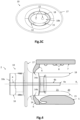
- FIG 4 represents schematically and partially, from the side, the mouthpiece 10 illustrated on the figure 1 partially introduced into an oral cavity. This is represented in longitudinal section, and the tongue 5, the teeth 6 and the palate 7 are represented schematically.
- the base 14 having two contact surfaces 14a, 14b, opposite each other with respect to the axis vertical and arranged on either side of the internal orifice 12. These contact surfaces 14a, 14b are intended to receive the teeth 6 of the subject, who then applies a tightening force towards each other.
- the mouthpiece 10 advantageously comprises a stop 17, here in the form of a collar, arranged on the base 14 and adjacent to the appendix 16, which can constitute a positioning reference with respect to the entrance of the oral cavity.
- the stop 17 is here a wall which extends transversely to the longitudinal axis A L , over at least part of the periphery of the base 14.
- the stop 17 is intended to press against the lips of the subject (not shown) when he bites the base 14, so that the appendix 16 and the stop 17 remain outside the oral cavity. It helps to seal the entrance to the oral cavity.
- the mouthpiece 10 comprises a second tongue 18, called a protective tongue, which is here substantially symmetrical to the retention tongue 15 with respect to the longitudinal axis A L (it is therefore opposite to the tab 15 along the vertical axis).
- a protective tongue which is a thin plate made of a rigid material, preferably identical to that of the structure of the end piece 10, which has a length along the longitudinal axis A L greater than its thickness. It has an exterior surface which is intended to come into contact with or opposite a surface which delimits the oral cavity, and an interior surface, opposite the exterior surface, which is intended to be opposite the pipe. sample 4 and the interior surface of the retention tab 15. It is oriented orthogonal to the vertical axis, and is therefore not horizontal.
- the protective tab 18 is intended to be at least facing a surface of the oral cavity, here facing the palate, to thus prevent any drops 8 from falling on the part internal 4b of the sampling pipe 4, and more precisely do not fall on the free end 4a. It therefore extends at a distance from the sampling pipe 4. Such drops could thus increase the humidity level of the gas sample taken, which can induce measurement noise during the characterization of the target compounds.
- Its length L lp is greater than or equal to the distance D along which the sampling pipe 4 extends along the longitudinal axis A L from the internal face 10b.
- the retention tabs 16 and protection 18 are here distinct from each other. They delimit an internal space in which the internal part 4b of the sampling pipe 4 is located. This internal space has a bottom opening 20 oriented towards the longitudinal axis A L and through which the gas sample is sucked in. Here it has two side openings 21, opposite each other along a transverse axis. Alternatively, the two tongues can join laterally via side walls, and thus form the same peripheral wall which extends continuously around the internal part 4b of the sampling pipe 4.
- this peripheral wall of containment and protection advantageously presents several through orifices (grooving, perforation, etc.), arranged at the level of a so-called horizontal transverse axis, that is to say orthogonal to the longitudinal axis A L and to the vertical axis (which is oriented from the tongue 5 towards the palate 7).
- the mouthpiece 10 comprises at least one internal conduit 13, with corresponding external 11 and internal 12 orifices, to allow the insertion of the sampling pipe 4 and therefore the collection of the gaseous breath sample.
- the mouthpiece 10 comprises two interior conduits 13 allowing two pipes to be inserted and therefore two simultaneous breath samples to be taken.
- the mouthpiece 10 comprises a single interior conduit 13, or as many interior conduits 13 as desired simultaneous samples.
- the pipes can have different insertion depths, to measure different target compounds or a concentration gradient of the same target compound.
- An internal conduit 13 has dimensions adapted to those of the sampling pipe 4 to allow insertion and withdrawal of the pipe while limiting fluid exchanges between the outside air and the breath located in the oral cavity.
- the mouthpiece here comprises a tubular rim 19 extending the cylindrical profile of the base 14 and therefore extending with respect to the base 14 along the longitudinal axis A L , the internal orifices 12 opening into the space delimited by this tubular rim 19.
- the mouthpiece 10 is preferably made in one piece, for example by injection molding in a resin suitable for common sterilization processes.
- the base 14 is full (without main opening, except the internal conduit(s) to ensure the passage of the sampling pipe(s). Its constitution with a retention tab 15 and a protection tab 18 identical to each other, extending symmetrically along the longitudinal axis A L , simplifies use by reducing the instructions to the sole directive of put one of the two elements against the subject's tongue.
- the mouthpiece 10 is first sterilized by any known method, for example by steam in an autoclave device. It is then possibly cleaned to remove any traces of sterilization product that could interfere with the breath sample.
- the mouthpiece 10 is firstly equipped with at least one removable and disposable sampling pipe 4.
- the sampling pipe 4 is inserted into the internal conduit 13 and thus passes through the base 14 and the appendix 16, projecting on the one hand through the external orifice 11 and on the other hand through the internal orifice 12. From the internal orifice 12, the pipe 4 extends along the longitudinal axis A L up to a calibrated distance D defined between the internal face 10b and the free end 4a of the pipe 4.
- sampling pipe 4 The opposite end of the sampling pipe 4 is connected to an analysis device 3 adapted to carry out sampling by aspiration, detection and characterization of the target compounds present in the gas sample.
- the gripping appendage 14 is grasped by the subject, and the mouthpiece 10 is introduced into the mouth, so that the retention tab 15 comes against the tongue 5 of the subject which then clamps its teeth 6 on the base 14 by placing its lips in contact with the stop 17.
- the entrance to the oral cavity is then closed.
- the analysis device 3 is then activated to take the breath sample by aspiration and then characterize the target compounds.
- the gas sample is sucked through the free end 4a of the sampling pipe 4, that is to say at a longitudinal distance D calibrated inside the subject's mouth.
- This distance D is chosen according to the precise sampling area desired, which may require sampling, for example, rather near the teeth or rather towards the bottom of the oral cavity.
- the sample is preferably taken towards the back of the oral cavity as it appears that the concentration of sulfur compounds to be characterized is higher there.
- the tip 10 blocks the entrance to the oral cavity, and the dimensions of the internal conduit 13 like those of the pipe 4 are insufficient to allow the subject to breathing through the mouth or allowing a fluid exchange between breath and the outside air. This prevents the breath from being diluted in the pulmonary air flow, so that the concentration of the target compounds to be characterized is not degraded.
- the retention tab 15 prevents the subject's tongue 5 from coming into contact with the sampling pipe 4 and thus prevents the subject's saliva from disturbing the breath sampling, for example by introducing into the breath taken from the steam resulting from the evaporation of saliva near the free end 4a.
- the protective tab 18 protects the sampling pipe 4, and its free end 4a, from falling droplets 8 of saliva, for example, coming from the palate 7 of the subject, so as not to disrupt the breath sampling.
- the interior conduits 13 may have different sections, and therefore accommodate sampling pipes 4 of different sections or diameters.
- sampling pipes 4 can be connected to the same analysis device, or to two different analysis devices each carrying out a different analysis of its respective sample. They can have different penetration depths.
- Two simultaneous breath samples can be taken with their respective section for the sampling pipes 4 as well as their respective calibrated distance D.
- Two simultaneous samples with sampling pipes 4 positioned at two different calibrated distances D make it possible to take two samples at two different depths in the oral cavity.
- the base 14 can include a sheath projecting with respect to the internal face 10b along the axis A L and opening onto the internal orifice 12, ensuring additional mechanical support of the internal part 4b of the pipe. sampling 4.
- the stop 17 can also be provided to come directly against the teeth of the subject rather than against his lips.
- the stop 17 can then be formed by a groove made in the base 14, or by a collar of suitable diameter.
Landscapes
- Health & Medical Sciences (AREA)
- Life Sciences & Earth Sciences (AREA)
- Engineering & Computer Science (AREA)
- Physics & Mathematics (AREA)
- Biomedical Technology (AREA)
- Molecular Biology (AREA)
- Pathology (AREA)
- Biophysics (AREA)
- General Health & Medical Sciences (AREA)
- Surgery (AREA)
- Public Health (AREA)
- Animal Behavior & Ethology (AREA)
- Medical Informatics (AREA)
- Veterinary Medicine (AREA)
- Heart & Thoracic Surgery (AREA)
- Pulmonology (AREA)
- Physiology (AREA)
- Chemical & Material Sciences (AREA)
- Urology & Nephrology (AREA)
- Immunology (AREA)
- General Physics & Mathematics (AREA)
- Biochemistry (AREA)
- Analytical Chemistry (AREA)
- Medicinal Chemistry (AREA)
- Food Science & Technology (AREA)
- Hematology (AREA)
- Dentistry (AREA)
- Oral & Maxillofacial Surgery (AREA)
- Investigating Or Analysing Biological Materials (AREA)
- Sampling And Sample Adjustment (AREA)
- Measurement Of The Respiration, Hearing Ability, Form, And Blood Characteristics Of Living Organisms (AREA)
- Measuring And Recording Apparatus For Diagnosis (AREA)
Claims (13)
- Vorrichtung (2) zum Entnehmen einer gasförmigen Atemprobe von einem Benutzer und einer enthaltenden Zielverbindung, die dazu bestimmt ist, von einer Analysevorrichtung (3) charakterisiert zu werden, enthaltend:o ein Mundstück (10) zum Entnehmen der gasförmigen Probe, das dazu ausgelegt ist, die Mundhöhle des Benutzers zu verschließen, und Folgendes umfasst:• eine erste, Außenfläche genannte, Fläche (10a), die dazu bestimmt ist, sich außerhalb der Mundhöhle zu befinden, und an der eine äußere Öffnung (11) mündet;• eine zweite, Innenfläche genannte, Fläche (10b), die dazu bestimmt ist, in die Mundhöhle eingeführt zu werden, die der Außenfläche (10a) entlang einer Längsachse AL des Mundstücks (10) gegenüberliegt und an der eine innere Öffnung (12) mündet, die durch einen inneren Kanal (13) mit der äußeren Öffnung (11) verbunden ist;• eine Positionierungsbasis (14), die die innere Fläche (10b) und eine obere und eine untere Kontaktfläche (14a, 14b) umfasst, die dazu bestimmt sind, mit den Zähnen des Benutzers in Kontakt zu stehen, wenn er sicherstellt, dass das Mundstück in der Mundhöhle gehalten wird, wobei sich die untere und die obere Kontaktfläche auf beiden Seiten der inneren Öffnung (12) entlang einer vertikalen Achse befinden;o dadurch gekennzeichnet, dass das Mundstück (10) eine erste Haltelasche (15) umfasst, die dazu bestimmt ist, in Kontakt mit der Zunge des Benutzers zu kommen, die aus einer dünnen Platte gebildet ist, die orthogonal zur vertikalen Achse ausgerichtet ist und sich von der inneren Fläche (10b) und der Seite der unteren Kontaktfläche (14b) der Basis (14) entlang der Längsachse AL über eine erste vordefinierte Länge Llc erstreckt;o und dadurch, dass die Entnahmevorrichtung (2) ein abnehmbares Entnahmerohr (4) umfasst, das dazu bestimmt ist, mit der Analysevorrichtung (3) verbunden zu werden, und das von dem Mundstück (10) abgenommen werden kann, das durch den inneren Kanal (13) verläuft und sich entlang der Längsachse AL und gegenüber der Haltelasche (15) über eine Distanz D erstreckt, die kleiner oder gleich der ersten Länge Llc ist, so dass die Haltelasche (15) jeglichen Kontakt der Zunge des Benutzers mit dem Entnahmerohr (4) verhindert.
- Entnahmevorrichtung (2) nach Anspruch 1, die eine zweite Schutzlasche (18) umfasst, die aus einer dünnen Platte gebildet ist, die orthogonal zur vertikalen Achse ausgerichtet ist und sich von der inneren Fläche (10b) und der Seite der oberen Fläche (14a) der Basis (14) entlang der Längsachse AL über eine erste vordefinierte Länge Llp erstreckt, die größer oder gleich der Distanz D ist, von dem abnehmbaren Entnahmerohr (4) beabstandet und gegenüber der Haltelasche (15) entlang der vertikalen Achse angeordnet ist.
- Entnahmevorrichtung (2) nach Anspruch 2, wobei die Haltelasche (15) und die Schutzlasche (18) identische Formen aufweisen und sich symmetrisch auf beiden Seiten der Längsachse AL erstrecken.
- Entnahmevorrichtung (2) nach einem der Ansprüche 1 bis 3, die einen Anschlag (17) umfasst, der auf der Positionierungsbasis (14) angeordnet und dazu bestimmt ist, mit einem Eingang der Mundhöhle in Kontakt zu gelangen.
- Entnahmevorrichtung (2) nach Anspruch 4, wobei der Anschlag (17) aus einem vorstehenden Flansch gebildet ist, der der Positionierungsbasis (14) zugewandt ist.
- Entnahmevorrichtung (2) nach einem der Ansprüche 1 bis 5, die einen Greiffortsatz (16) umfasst, der sich in einer Verlängerung der Positionierungsbasis (14) entlang der Längsachse AL erstreckt, wobei der Greiffortsatz (16) die äußere Fläche (10a) umfasst.
- Entnahmevorrichtung (2) nach einem der vorhergehenden Ansprüche, dadurch gekennzeichnet, dass die Positionierungsbasis (14) eine zylindrische Form aufweist, die zwei Kontaktflächen definiert, die gekrümmt sind und einander entlang einer zur Längsachse AL orthogonal liegenden Achse gegenüberliegen.
- Entnahmevorrichtung (2) nach einem der vorhergehenden Ansprüche, die einen vorstehenden rohrförmigen Rand (19) umfasst, der der Positionierungsbasis (14) entlang der Längsachse AL zugewandt ist.
- Entnahmevorrichtung (2) nach einem der vorhergehenden Ansprüche, die eine Vielzahl von inneren Kanälen (13) umfasst, die jeweils ein Entnahmerohr (4) aufnehmen.
- Analysesystem (1), das eine Entnahmevorrichtung (2) nach einem der vorhergehenden Ansprüche und eine Analysevorrichtung (3) umfasst, die mit dem Entnahmerohr (4) verbunden ist.
- Analysesystem (1) nach Anspruch 10, wobei die Analysevorrichtung eine Messkammer umfasst, die dazu bestimmt ist, die in der gasförmigen Probe enthaltenen Zielverbindungen aufzunehmen, in der sich eine Vielzahl von verschiedenen empfindlichen Stellen befindet, die jeweils Empfänger umfassen, der dazu geeignet sind, mit den Zielverbindungen zu interagieren, wobei die Analysevorrichtung einen Oberflächenplasmonenresonanz-Bildgebungsdetektor oder eine Vielzahl von separaten elektromechanischen Resonatoren umfasst, die jeweils eine empfindliche Stelle bilden.
- Entnahmeverfahren mittels der Entnahmevorrichtung (2) nach einem der Ansprüche 1 bis 9, wobei das Mundstück (10) teilweise in die Mundhöhle des Benutzers hinsichtlich einer Atementnahme eingeführt wird, wobei die Haltelasche (15) in Kontakt mit der Zunge (5) des Patienten gebracht wird.
- Entnahmeverfahren nach Anspruch 12, wobei der Benutzer während des Entnehmens der gasförmigen Atemprobe durch die Nase atmet.
Applications Claiming Priority (2)
| Application Number | Priority Date | Filing Date | Title |
|---|---|---|---|
| FR2006978A FR3112073B1 (fr) | 2020-07-02 | 2020-07-02 | Dispositif de prélèvement comportant un embout à languette de contention |
| PCT/EP2021/068105 WO2022003076A1 (fr) | 2020-07-02 | 2021-06-30 | Dispositif de prelevement comportant un embout a languette de contention |
Publications (3)
| Publication Number | Publication Date |
|---|---|
| EP4175541A1 EP4175541A1 (de) | 2023-05-10 |
| EP4175541B1 true EP4175541B1 (de) | 2024-07-31 |
| EP4175541C0 EP4175541C0 (de) | 2024-07-31 |
Family
ID=73138915
Family Applications (1)
| Application Number | Title | Priority Date | Filing Date |
|---|---|---|---|
| EP21737670.6A Active EP4175541B1 (de) | 2020-07-02 | 2021-06-30 | Vorrichtung zum sammeln von gasförmigen atemproben, und sammelverfahren mittels der vorrichtung |
Country Status (6)
| Country | Link |
|---|---|
| US (1) | US20230255511A1 (de) |
| EP (1) | EP4175541B1 (de) |
| JP (1) | JP2023532719A (de) |
| KR (1) | KR20230031920A (de) |
| FR (1) | FR3112073B1 (de) |
| WO (1) | WO2022003076A1 (de) |
Family Cites Families (6)
| Publication number | Priority date | Publication date | Assignee | Title |
|---|---|---|---|---|
| US6244865B1 (en) * | 1999-12-06 | 2001-06-12 | Sensormedics Corporation | Tongue positioning device with optional filter |
| CN2728435Y (zh) * | 2004-08-03 | 2005-09-28 | 上海雅锋医疗器械有限公司 | 监护型胃镜咬口器 |
| FR2992223B1 (fr) * | 2012-06-21 | 2015-05-01 | Deltamedics | Canule oropharyngee comprenant une arrivee de dioxygene et une extraction de dioxyde de carbone |
| GB2506863A (en) | 2012-10-09 | 2014-04-16 | Univ Dublin City | System and method for analysing and measuring ammonia levels in a sample |
| EP2968814B1 (de) * | 2013-03-15 | 2017-09-27 | Airway Control Technologies, LLC | Medizinische beatmungsvorrichtung |
| FR3046153A1 (fr) | 2015-12-24 | 2017-06-30 | Commissariat Energie Atomique | Systeme presentant une densite surfacique de dispositfs microelectromecaniques et/ou nanoelectromecaniques augmentee |
-
2020
- 2020-07-02 FR FR2006978A patent/FR3112073B1/fr active Active
-
2021
- 2021-06-30 WO PCT/EP2021/068105 patent/WO2022003076A1/fr not_active Ceased
- 2021-06-30 EP EP21737670.6A patent/EP4175541B1/de active Active
- 2021-06-30 US US18/014,149 patent/US20230255511A1/en not_active Abandoned
- 2021-06-30 KR KR1020237003449A patent/KR20230031920A/ko not_active Withdrawn
- 2021-06-30 JP JP2022581406A patent/JP2023532719A/ja active Pending
Also Published As
| Publication number | Publication date |
|---|---|
| JP2023532719A (ja) | 2023-07-31 |
| FR3112073B1 (fr) | 2024-10-18 |
| FR3112073A1 (fr) | 2022-01-07 |
| US20230255511A1 (en) | 2023-08-17 |
| WO2022003076A1 (fr) | 2022-01-06 |
| KR20230031920A (ko) | 2023-03-07 |
| EP4175541C0 (de) | 2024-07-31 |
| EP4175541A1 (de) | 2023-05-10 |
Similar Documents
| Publication | Publication Date | Title |
|---|---|---|
| WO2009106760A2 (fr) | Dispositif et procédé pour isoler et cultiver des cellules vivantes sur filtre ou extraire leur matériel génétique | |
| CN103857346B (zh) | 用于采集生物样品的装置和相应的方法 | |
| EP0731666B1 (de) | Vorrichtung zur messung der maximalströmung der ausatemluft | |
| EP3152542B1 (de) | Anordnung zum aufnehmen und transportieren von in aerosolen enthaltenen nanoobjekten mit einer kassette, deren öffnung während der probennahme gesichert ist | |
| FR2952069A1 (fr) | Dispositif et procede pour isoler et/ou cultiver des cellules vivantes sur filtre ou extraire leur materiel genetique | |
| JP2023096083A (ja) | 可搬型流体試料採取装置、それを用いるためのシステム、及びその製造及び使用方法 | |
| FR2878325A1 (fr) | Procede et dispositif de mesure de parametres d'ecoulement | |
| FR3003176A1 (fr) | Canule nasopharyngee pour capnographie en flux secondaire | |
| WO2022003076A1 (fr) | Dispositif de prelevement comportant un embout a languette de contention | |
| JP2010502995A (ja) | 一体型サンプルセル及びフィルタ並びにそれらを用いたシステム | |
| US7121134B2 (en) | Integrated sample cell and filter and system using same | |
| EP2863977B1 (de) | Mund- und rachenkanüle mit einem sauerstoffeinlass und einem kohlendioxidauslass | |
| US20240210323A1 (en) | Measurement chamber extension for spectrophotometric characterization of a sterile liquid in a polymer container by nir- or raman-spectrophotometry | |
| WO2004110281A2 (fr) | Trocart de ponction de moelle osseuse | |
| FR3054884A1 (fr) | Dispositif d'analyse d'un gaz de respiration anesthesique, et respirateur d'anesthesie | |
| FR2801660A1 (fr) | Dispositif de manipulation d'un porte-support solide pour contaminants | |
| WO2016023747A1 (fr) | Canule oropharyngée modulaire | |
| EP2737300A1 (de) | Kopf für einen evaneszenzwellen-glasfasersensor | |
| EP1477128B1 (de) | Baugruppe bestehend aus einer Verschlusskappe und einer intramammären Injektionsspritze | |
| EP2878959B1 (de) | Vorrichtung und Verfahren zur Kontrolle einer Druckmesssonde eines Flusses | |
| FR2876919A1 (fr) | Aiguille de maintien comportant des joues de prehension. | |
| CH623931A5 (en) | Element with an opening which can be used in a particle analysis apparatus | |
| CN114026419B (zh) | 低流通瓶 | |
| FR3081321A1 (fr) | Dispositif de collecte de semence animale | |
| EP4225151A1 (de) | Endkappe für vorrichtung zur entnahme biologischer proben und entnahmevorrichtung damit |
Legal Events
| Date | Code | Title | Description |
|---|---|---|---|
| STAA | Information on the status of an ep patent application or granted ep patent |
Free format text: STATUS: UNKNOWN |
|
| STAA | Information on the status of an ep patent application or granted ep patent |
Free format text: STATUS: THE INTERNATIONAL PUBLICATION HAS BEEN MADE |
|
| PUAI | Public reference made under article 153(3) epc to a published international application that has entered the european phase |
Free format text: ORIGINAL CODE: 0009012 |
|
| STAA | Information on the status of an ep patent application or granted ep patent |
Free format text: STATUS: REQUEST FOR EXAMINATION WAS MADE |
|
| 17P | Request for examination filed |
Effective date: 20230102 |
|
| AK | Designated contracting states |
Kind code of ref document: A1 Designated state(s): AL AT BE BG CH CY CZ DE DK EE ES FI FR GB GR HR HU IE IS IT LI LT LU LV MC MK MT NL NO PL PT RO RS SE SI SK SM TR |
|
| DAV | Request for validation of the european patent (deleted) | ||
| DAX | Request for extension of the european patent (deleted) | ||
| GRAP | Despatch of communication of intention to grant a patent |
Free format text: ORIGINAL CODE: EPIDOSNIGR1 |
|
| STAA | Information on the status of an ep patent application or granted ep patent |
Free format text: STATUS: GRANT OF PATENT IS INTENDED |
|
| INTG | Intention to grant announced |
Effective date: 20240216 |
|
| GRAS | Grant fee paid |
Free format text: ORIGINAL CODE: EPIDOSNIGR3 |
|
| GRAA | (expected) grant |
Free format text: ORIGINAL CODE: 0009210 |
|
| STAA | Information on the status of an ep patent application or granted ep patent |
Free format text: STATUS: THE PATENT HAS BEEN GRANTED |
|
| AK | Designated contracting states |
Kind code of ref document: B1 Designated state(s): AL AT BE BG CH CY CZ DE DK EE ES FI FR GB GR HR HU IE IS IT LI LT LU LV MC MK MT NL NO PL PT RO RS SE SI SK SM TR |
|
| REG | Reference to a national code |
Ref country code: CH Ref legal event code: EP Ref country code: GB Ref legal event code: FG4D Free format text: NOT ENGLISH |
|
| REG | Reference to a national code |
Ref country code: DE Ref legal event code: R096 Ref document number: 602021016513 Country of ref document: DE |
|
| REG | Reference to a national code |
Ref country code: IE Ref legal event code: FG4D Free format text: LANGUAGE OF EP DOCUMENT: FRENCH |
|
| U01 | Request for unitary effect filed |
Effective date: 20240828 |
|
| U07 | Unitary effect registered |
Designated state(s): AT BE BG DE DK EE FI FR IT LT LU LV MT NL PT RO SE SI Effective date: 20240905 |
|
| PG25 | Lapsed in a contracting state [announced via postgrant information from national office to epo] |
Ref country code: NO Free format text: LAPSE BECAUSE OF FAILURE TO SUBMIT A TRANSLATION OF THE DESCRIPTION OR TO PAY THE FEE WITHIN THE PRESCRIBED TIME-LIMIT Effective date: 20241031 |
|
| PG25 | Lapsed in a contracting state [announced via postgrant information from national office to epo] |
Ref country code: PL Free format text: LAPSE BECAUSE OF FAILURE TO SUBMIT A TRANSLATION OF THE DESCRIPTION OR TO PAY THE FEE WITHIN THE PRESCRIBED TIME-LIMIT Effective date: 20240731 Ref country code: GR Free format text: LAPSE BECAUSE OF FAILURE TO SUBMIT A TRANSLATION OF THE DESCRIPTION OR TO PAY THE FEE WITHIN THE PRESCRIBED TIME-LIMIT Effective date: 20241101 |
|
| PG25 | Lapsed in a contracting state [announced via postgrant information from national office to epo] |
Ref country code: IS Free format text: LAPSE BECAUSE OF FAILURE TO SUBMIT A TRANSLATION OF THE DESCRIPTION OR TO PAY THE FEE WITHIN THE PRESCRIBED TIME-LIMIT Effective date: 20241130 |
|
| PG25 | Lapsed in a contracting state [announced via postgrant information from national office to epo] |
Ref country code: HR Free format text: LAPSE BECAUSE OF FAILURE TO SUBMIT A TRANSLATION OF THE DESCRIPTION OR TO PAY THE FEE WITHIN THE PRESCRIBED TIME-LIMIT Effective date: 20240731 |
|
| PG25 | Lapsed in a contracting state [announced via postgrant information from national office to epo] |
Ref country code: RS Free format text: LAPSE BECAUSE OF FAILURE TO SUBMIT A TRANSLATION OF THE DESCRIPTION OR TO PAY THE FEE WITHIN THE PRESCRIBED TIME-LIMIT Effective date: 20241031 Ref country code: ES Free format text: LAPSE BECAUSE OF FAILURE TO SUBMIT A TRANSLATION OF THE DESCRIPTION OR TO PAY THE FEE WITHIN THE PRESCRIBED TIME-LIMIT Effective date: 20240731 |
|
| PG25 | Lapsed in a contracting state [announced via postgrant information from national office to epo] |
Ref country code: RS Free format text: LAPSE BECAUSE OF FAILURE TO SUBMIT A TRANSLATION OF THE DESCRIPTION OR TO PAY THE FEE WITHIN THE PRESCRIBED TIME-LIMIT Effective date: 20241031 Ref country code: PL Free format text: LAPSE BECAUSE OF FAILURE TO SUBMIT A TRANSLATION OF THE DESCRIPTION OR TO PAY THE FEE WITHIN THE PRESCRIBED TIME-LIMIT Effective date: 20240731 Ref country code: NO Free format text: LAPSE BECAUSE OF FAILURE TO SUBMIT A TRANSLATION OF THE DESCRIPTION OR TO PAY THE FEE WITHIN THE PRESCRIBED TIME-LIMIT Effective date: 20241031 Ref country code: IS Free format text: LAPSE BECAUSE OF FAILURE TO SUBMIT A TRANSLATION OF THE DESCRIPTION OR TO PAY THE FEE WITHIN THE PRESCRIBED TIME-LIMIT Effective date: 20241130 Ref country code: HR Free format text: LAPSE BECAUSE OF FAILURE TO SUBMIT A TRANSLATION OF THE DESCRIPTION OR TO PAY THE FEE WITHIN THE PRESCRIBED TIME-LIMIT Effective date: 20240731 Ref country code: GR Free format text: LAPSE BECAUSE OF FAILURE TO SUBMIT A TRANSLATION OF THE DESCRIPTION OR TO PAY THE FEE WITHIN THE PRESCRIBED TIME-LIMIT Effective date: 20241101 Ref country code: ES Free format text: LAPSE BECAUSE OF FAILURE TO SUBMIT A TRANSLATION OF THE DESCRIPTION OR TO PAY THE FEE WITHIN THE PRESCRIBED TIME-LIMIT Effective date: 20240731 |
|
| PG25 | Lapsed in a contracting state [announced via postgrant information from national office to epo] |
Ref country code: SM Free format text: LAPSE BECAUSE OF FAILURE TO SUBMIT A TRANSLATION OF THE DESCRIPTION OR TO PAY THE FEE WITHIN THE PRESCRIBED TIME-LIMIT Effective date: 20240731 |
|
| PG25 | Lapsed in a contracting state [announced via postgrant information from national office to epo] |
Ref country code: CZ Free format text: LAPSE BECAUSE OF FAILURE TO SUBMIT A TRANSLATION OF THE DESCRIPTION OR TO PAY THE FEE WITHIN THE PRESCRIBED TIME-LIMIT Effective date: 20240731 |
|
| PG25 | Lapsed in a contracting state [announced via postgrant information from national office to epo] |
Ref country code: SK Free format text: LAPSE BECAUSE OF FAILURE TO SUBMIT A TRANSLATION OF THE DESCRIPTION OR TO PAY THE FEE WITHIN THE PRESCRIBED TIME-LIMIT Effective date: 20240731 |
|
| PLBE | No opposition filed within time limit |
Free format text: ORIGINAL CODE: 0009261 |
|
| STAA | Information on the status of an ep patent application or granted ep patent |
Free format text: STATUS: NO OPPOSITION FILED WITHIN TIME LIMIT |
|
| 26N | No opposition filed |
Effective date: 20250501 |
|
| U20 | Renewal fee for the european patent with unitary effect paid |
Year of fee payment: 5 Effective date: 20250627 |
|
| U1N | Appointed representative for the unitary patent procedure changed after the registration of the unitary effect |
Representative=s name: SANTARELLI; FR |
|
| REG | Reference to a national code |
Ref country code: CH Ref legal event code: H13 Free format text: ST27 STATUS EVENT CODE: U-0-0-H10-H13 (AS PROVIDED BY THE NATIONAL OFFICE) Effective date: 20260127 |
|
| PG25 | Lapsed in a contracting state [announced via postgrant information from national office to epo] |
Ref country code: MC Free format text: LAPSE BECAUSE OF FAILURE TO SUBMIT A TRANSLATION OF THE DESCRIPTION OR TO PAY THE FEE WITHIN THE PRESCRIBED TIME-LIMIT Effective date: 20240731 |
|
| GBPC | Gb: european patent ceased through non-payment of renewal fee |
Effective date: 20250630 |
|
| PG25 | Lapsed in a contracting state [announced via postgrant information from national office to epo] |
Ref country code: GB Free format text: LAPSE BECAUSE OF NON-PAYMENT OF DUE FEES Effective date: 20250630 |
|
| PG25 | Lapsed in a contracting state [announced via postgrant information from national office to epo] |
Ref country code: IE Free format text: LAPSE BECAUSE OF NON-PAYMENT OF DUE FEES Effective date: 20250630 |
|
| PG25 | Lapsed in a contracting state [announced via postgrant information from national office to epo] |
Ref country code: CH Free format text: LAPSE BECAUSE OF NON-PAYMENT OF DUE FEES Effective date: 20250630 |