EP4175263A1 - Transmission structure and electronic device - Google Patents
Transmission structure and electronic device Download PDFInfo
- Publication number
- EP4175263A1 EP4175263A1 EP21832980.3A EP21832980A EP4175263A1 EP 4175263 A1 EP4175263 A1 EP 4175263A1 EP 21832980 A EP21832980 A EP 21832980A EP 4175263 A1 EP4175263 A1 EP 4175263A1
- Authority
- EP
- European Patent Office
- Prior art keywords
- transmission
- camera module
- support
- functional
- module
- Prior art date
- Legal status (The legal status is an assumption and is not a legal conclusion. Google has not performed a legal analysis and makes no representation as to the accuracy of the status listed.)
- Granted
Links
Images

Classifications
-
- H—ELECTRICITY
- H04—ELECTRIC COMMUNICATION TECHNIQUE
- H04M—TELEPHONIC COMMUNICATION
- H04M1/00—Substation equipment, e.g. for use by subscribers
- H04M1/02—Constructional features of telephone sets
- H04M1/0202—Portable telephone sets, e.g. cordless phones, mobile phones or bar type handsets
- H04M1/026—Details of the structure or mounting of specific components
-
- H—ELECTRICITY
- H04—ELECTRIC COMMUNICATION TECHNIQUE
- H04M—TELEPHONIC COMMUNICATION
- H04M1/00—Substation equipment, e.g. for use by subscribers
- H04M1/02—Constructional features of telephone sets
- H04M1/0202—Portable telephone sets, e.g. cordless phones, mobile phones or bar type handsets
- H04M1/026—Details of the structure or mounting of specific components
- H04M1/0264—Details of the structure or mounting of specific components for a camera module assembly
-
- G—PHYSICS
- G03—PHOTOGRAPHY; CINEMATOGRAPHY; ANALOGOUS TECHNIQUES USING WAVES OTHER THAN OPTICAL WAVES; ELECTROGRAPHY; HOLOGRAPHY
- G03B—APPARATUS OR ARRANGEMENTS FOR TAKING PHOTOGRAPHS OR FOR PROJECTING OR VIEWING THEM; APPARATUS OR ARRANGEMENTS EMPLOYING ANALOGOUS TECHNIQUES USING WAVES OTHER THAN OPTICAL WAVES; ACCESSORIES THEREFOR
- G03B11/00—Filters or other obturators specially adapted for photographic purposes
- G03B11/04—Hoods or caps for eliminating unwanted light from lenses, viewfinders or focusing aids
- G03B11/043—Protective lens closures or lens caps built into cameras
-
- G—PHYSICS
- G03—PHOTOGRAPHY; CINEMATOGRAPHY; ANALOGOUS TECHNIQUES USING WAVES OTHER THAN OPTICAL WAVES; ELECTROGRAPHY; HOLOGRAPHY
- G03B—APPARATUS OR ARRANGEMENTS FOR TAKING PHOTOGRAPHS OR FOR PROJECTING OR VIEWING THEM; APPARATUS OR ARRANGEMENTS EMPLOYING ANALOGOUS TECHNIQUES USING WAVES OTHER THAN OPTICAL WAVES; ACCESSORIES THEREFOR
- G03B17/00—Details of cameras or camera bodies; Accessories therefor
- G03B17/02—Bodies
- G03B17/04—Bodies collapsible, foldable or extensible, e.g. book type
-
- G—PHYSICS
- G03—PHOTOGRAPHY; CINEMATOGRAPHY; ANALOGOUS TECHNIQUES USING WAVES OTHER THAN OPTICAL WAVES; ELECTROGRAPHY; HOLOGRAPHY
- G03B—APPARATUS OR ARRANGEMENTS FOR TAKING PHOTOGRAPHS OR FOR PROJECTING OR VIEWING THEM; APPARATUS OR ARRANGEMENTS EMPLOYING ANALOGOUS TECHNIQUES USING WAVES OTHER THAN OPTICAL WAVES; ACCESSORIES THEREFOR
- G03B30/00—Camera modules comprising integrated lens units and imaging units, specially adapted for being embedded in other devices, e.g. mobile phones or vehicles
-
- H—ELECTRICITY
- H04—ELECTRIC COMMUNICATION TECHNIQUE
- H04M—TELEPHONIC COMMUNICATION
- H04M1/00—Substation equipment, e.g. for use by subscribers
- H04M1/02—Constructional features of telephone sets
- H04M1/0202—Portable telephone sets, e.g. cordless phones, mobile phones or bar type handsets
- H04M1/0249—Details of the mechanical connection between the housing parts or relating to the method of assembly
-
- H—ELECTRICITY
- H04—ELECTRIC COMMUNICATION TECHNIQUE
- H04N—PICTORIAL COMMUNICATION, e.g. TELEVISION
- H04N23/00—Cameras or camera modules comprising electronic image sensors; Control thereof
- H04N23/57—Mechanical or electrical details of cameras or camera modules specially adapted for being embedded in other devices
-
- H—ELECTRICITY
- H04—ELECTRIC COMMUNICATION TECHNIQUE
- H04M—TELEPHONIC COMMUNICATION
- H04M1/00—Substation equipment, e.g. for use by subscribers
- H04M1/02—Constructional features of telephone sets
- H04M1/0202—Portable telephone sets, e.g. cordless phones, mobile phones or bar type handsets
- H04M1/0206—Portable telephones comprising a plurality of mechanically joined movable body parts, e.g. hinged housings
- H04M1/0208—Portable telephones comprising a plurality of mechanically joined movable body parts, e.g. hinged housings characterized by the relative motions of the body parts
- H04M1/0235—Slidable or telescopic telephones, i.e. with a relative translation movement of the body parts; Telephones using a combination of translation and other relative motions of the body parts
Definitions
- This application relates to the field of communications technologies, and in particular to a transmission structure and an electronic device.
- an elevation-type camera has become a development trend as a feasible solution. Movement of the camera is driven by a driving mechanism, and a position of the camera can be flexibly adjusted according to user demands.
- other components of the electronic device are still disposed in fixed positions and cannot be flexibly adjusted according to use conditions of a user.
- the fixed components occupy outer surface space of the electronic device, which is not conducive to increase of a screen-to-body ratio.
- Embodiments of this application provide a transmission structure and an electronic device, so that a problem that a low screen-to-body ratio is caused by a functional component of an existing electronic device can be resolved.
- An embodiment of this application provides a transmission structure, including: a driving member, a transmission assembly, a camera module, and a functional module, where the driving member is connected to the camera module, and the camera module is connected to the functional module through the transmission assembly, where the camera module includes at least one camera, and the functional module includes a first functional component and a second functional component arranged along a first direction; and in a case that the driving member drives the camera module to move along a second direction, the transmission assembly drives the functional module to move along the first direction, and an angle between the first direction and the second direction is greater than 0°.
- An embodiment of this application further provides an electronic device, including a housing and the foregoing transmission structure, where the transmission structure is located in the housing, and the housing is provided with an opening and a light transmission hole, the driving member can drive the camera module to move between a first position and a second position, and the transmission assembly drives the functional module to move between a third position and a fourth position, where in a case that the camera module is located at the first position, the functional module is located at the third position, the camera module at least partially passes through the opening and is located outside the housing, and the first functional component is opposite to the light transmission hole; and in a case that the camera module is located at the second position, the functional module is located at the fourth position, the camera module is hidden in the housing, and the second functional component is opposite to the light transmission hole.
- the camera module and the functional module are connected through the transmission assembly, so that when the camera module driven by the driving member moves along the second direction, the camera module can drive the transmission assembly to move, further driving the functional module to move along the first direction, so as to achieve link movement of the functional module and the camera module.
- movement of the functional module is driven by movement of the camera module, so that a fixed position for an existing functional module can be changed, to meet a user's demand for changing a position of the functional module.
- embodiments of this application provide an electronic device, including a housing 10 and a transmission structure, and the housing is provided with an opening (not shown) and a light transmission hole (not shown).
- the transmission structure includes a driving member (not shown), a transmission assembly 20, a camera module 30, and a functional module.
- the driving member is connected to the camera module 30, and the camera module 30 is also connected to the functional module through the transmission assembly 20.
- the camera module 30 includes at least one camera, and the functional module includes a first functional component 41 and a second functional component 42 arranged along a first direction.
- the driving member drives the camera module 30 to move along a second direction
- the transmission assembly 20 drives the functional module to move along the first direction, and an angle between the first direction and the second direction is greater than 0°.
- the camera module 30 can move between a first position and a second position, and the transmission assembly 20 drives the functional module to move between a third position and a fourth position.
- the functional module In a case that the camera module 30 is located at the first position, the functional module is located at the third position, the camera module 30 at least partially passes through the opening and is located outside the housing 10, and the first functional component 41 is opposite to the light transmission hole. In a case that the camera module 30 is located at the second position, the functional module is located at the fourth position, the camera module 30 is hidden in the housing 10, and the second functional component 42 is opposite to the light transmission hole.
- the camera module 30 and the functional module are connected through the transmission assembly 20, so that when the camera module 30 driven by the driving member moves along the second direction, the camera module can drive the transmission assembly 20 to move, further driving the functional module to move along the first direction, so as to achieve link movement of the functional module and the camera module 30.
- movement of the functional module is driven by movement of the camera module 30, so that a fixed position for an existing functional module can be changed, to meet a user's demand for changing a position of the functional module.
- the camera module 30 and the functional module can move along different directions, so as to meet the user's demand for position change of the functional module.
- position change of the camera module 30 causes position change of the functional module, so that a position of the functional component included in the functional module can be adjusted according to a use scenario.
- the camera module 30 is located at the first position, the camera module 30 at least partially passes through the opening and is located outside the housing 10, the functional module is located at the third position, and the first functional component 41 of the functional module is opposite to the light transmission hole, to achieve a relevant function of the first functional component 41.
- the functional module is located at the fourth position in the housing 10 in which the camera module 30 is hidden, and the second functional component 42 of the functional module is opposite to the light transmission hole, to achieve a relevant function of the second functional component 42.
- the first functional component 41 and the second functional component 42 share one light transmission hole, so that the number of light transmission holes opened on the housing 10 can be effectively reduced, and then a problem of a screen-to-body ratio of the electronic device is small caused by excessively many light transmission holes can be reduced, and then the screen-to-body ratio of the electronic device can be increased.
- the first functional component 41 may be a flashlight
- the second functional component 42 may be an optical sensor
- the second functional component 42 may also be another functional component, such as a receiver.
- the first functional component 41 is the flashlight
- the second functional component 42 is the optical sensor for description as follows.
- the camera module 30 When the camera module 30 is located at the first position, the camera module 30 at least partially passes through the opening and is located outside the housing 10, the functional module is located at the third position, and the flashlight is opposite to the light transmission hole, so that a light filling function of the flashlight can be achieved, shooting requirements of the camera module 30 can be satisfied, and the optical sensor can be controlled to be in a non-working state, to reduce power consumption of the electronic device.
- the functional module is located at the fourth position in the housing 10 in which the camera module 30 is hidden, and the optical sensor is opposite to the light transmission hole, so as to achieve a relevant function of the optical sensor.
- the optical sensor is an infrared sensor
- an infrared detection function of the electronic device can be achieved, and the flashlight can be controlled to be turned off, that is, in a non-working state, so as to reduce the power consumption of the electronic device.
- the camera module 30 includes a camera assembly and a lifting assembly, the lifting assembly is connected to the camera assembly, the lifting assembly is also connected to the driving member, and the camera assembly is further connected to the transmission assembly 20. Under the action of the driving member, the lifting assembly drives the camera assembly to move, the camera assembly drives the transmission assembly 20 to move, and the transmission assembly 20 drives the functional module to move.
- the driving member is configured to drive the camera module 30 to move between the first position and the second position, that is, to drive the camera module 30 to switch between a protruding state and a retracting state.
- the driving member may be a driving motor configured to drive the lifting assembly to move; and the lifting assembly may be a screw drive assembly configured to drive the camera assembly to move.
- the light transmission hole may be a light transmission channel disposed at the housing 10 or an opening for light transmission.
- the light transmission hole is configured to achieve light interaction between the flashlight or the optical sensor and the outside, that is, the flashlight can emit light through the light transmission hole, and the optical sensor can emit light to the outside or receive light from the outside through the light transmission hole.
- the functional module further includes a support 50.
- the first functional component 41 and the second functional component 42 are disposed on the support 50.
- the transmission assembly 20 is connected to the support 50 and can drive the support 50 to move along the first direction.
- the first functional component 41 and the second functional component 42 are disposed on the support 50 and move together with the support 50.
- the first functional component 41 is the flashlight
- the first functional component 41 and the second functional component 42 share one light transmission hole, so that the number of light transmission holes opened at the housing 10 can be reduced, and a screen-to-body ratio of the electronic device can be increased to some extent.
- the functional module when the functional module is at the third position, that is, the flashlight is opposite to the light transmission hole and the optical sensor is hidden in the housing 10, a working state of the flashlight is controlled, to meet shooting requirements of a user, and the optical sensor is controlled to be in a non-working state, to reduce the power consumption of the electronic device.
- the functional module is at the fourth position, that is, the optical sensor is opposite to the light transmission hole and the flashlight is hidden in the housing 10
- the light sensor is controlled to be in a working state, to achieve infrared detection and other functions of the electronic device, and the flashlight is controlled to be off, that is, in a non-working state, to reduce the power consumption of the electronic device.
- An angle between the first direction and the second direction is 90°, that is, the first direction and the second direction are perpendicular, and a movement direction of the camera module 30 is perpendicular to a movement direction of the functional module.
- the movement direction of the camera module 30 is a length direction of the electronic device
- the movement direction of the functional module is a width direction of the electronic device.
- the support 50 provided with the flashlight and the optical sensor is located in the housing 10 and can move in the housing 10, such as left and right movement.
- movement of the support 50 can be implemented through an additional driving assembly, and the drive assembly can drive the transmission component 20 to move, further driving the support 50 to move, so that the support 50 can move to the third position or the fourth position, and a relevant function of the electronic device can be achieved.
- the camera module 30 and the support 50 can be connected by the transmission assembly 20, so that the support 50 can move along with the camera module 30.
- the support 50 moves to the third position, so that the electronic device can achieve a relevant function of the first functional component 41.
- the support 50 moves to the fourth position, so that the electronic device can achieve a relevant function of the second functional component 42.
- the camera module 30 and the support 50 can be connected by the transmission assembly 20, so that the support 50 can move along with the camera module 30, setting of the driving assembly can be skipped, and then space can be reduced, and layout of a functional component of the electronic device can be optimized.
- the transmission assembly 20 includes a first transmission member and a second transmission member.
- the first transmission member is connected to the camera module 30, the second transmission member is connected to the functional module, and the first transmission member is in transmission connection with the second transmission member.
- the second transmission member is connected to the support 50 of the functional module, and since the camera module 30 can move between the first position and the second position, the support 50 can move between the third position and the fourth position correspondingly.
- the support 50 When the camera module 30 is located at the first position, the support 50 is located at the third position, and the first functional component 41 is opposite to the light transmission hole.
- the support 50 When the camera module 30 is located at the second position, the support 50 is located at the fourth position, and the second functional component 42 is opposite to the light transmission hole.
- the camera module 30 and the support 50 are connected through the transmission assembly 20, so that the support 50 can move along with the camera module 30. Therefore, synchronous movement of the flashlight and the camera module can be implemented, and then shooting experience of the electronic device can be improved.
- the camera module 30 is at the first position, that is, the camera module 30 is at least partially located outside the housing 10 through the opening, so that the shooting function of the camera module 30 can be achieved.
- the flashlight Because the support 50 moves together with the camera module 30, when the camera module 30 is located at the first position, the flashlight also moves to a position facing the light transmission hole, so that a light filling function of the camera module 30 can be achieved, and then shooting experience of the electronic device can be improved.
- a camera module 30 is provided with a first spur rack 31, a first transmission member is a first gear, and the first gear is meshed with the first spur rack 31. Therefore, when the camera module 30 telescopically moves relative to the housing 10, the first spur rack 31 can drive the first gear to rotate, so that the camera module 30 can drive a transmission assembly 20 to move.
- a second transmission member is a second spur rack 21, and the second spur rack 21 is meshed with the first gear, so that the second spur rack 21 can move laterally under the action of the first gear.
- the second spur rack 21 is also fixedly connected to a support 50, so that the support 50 can move laterally together with the second spur rack 21, and a flashlight and an optical sensor located on the support 50 can move relative to a position of a light transmission hole.
- the optical sensor is disposed facing the light transmission hole, and the flashlight is hidden in a housing 10.
- the support 50 moves to a third position, the flashlight is disposed facing the light transmission hole, and the optical sensor is hidden in the housing 10.
- the support 50 and the second spur rack 21 can be an integral structure, that is, the spur rack can be disposed on the support 50 to form the second transmission member.
- a sliding member slidably connected to the support 50 can also be disposed in the housing 10, and the sliding member may be a sliding rail or a sliding groove disposed in the housing 10.
- a sliding groove matched with the sliding rail can be disposed on the support 50.
- a sliding rail or a sliding block matched with the sliding groove can be disposed on the support 50, so that movement of the support 50 in the housing 10 can be improved.
- a transmission mode for the gear and rack is characterized with a simple structure and small space, so that installation space required for the transmission assembly 20 can be reduced effectively.
- a position of the support 50 can also be switched in another transmission mode, such as a cam transmission mode or a slider-crank mechanism.
- a second transmission member may be an eccentric wheel 22.
- One end of a support 50 may abut against an outer peripheral surface of the eccentric wheel 22, and the other end of the support 50 can be connected to an inner side wall of a housing 10 through an elastic member 70.
- the support 50 can move to a third position or a fourth position by using a characteristic of the eccentric wheel 22.
- the elastic member 70 may be a spring, or a silicone tape or the like with an elastic function.
- the housing 10 is provided with a first sliding member (not shown), and the support 50 can be slidably connected to the first sliding member, so that the support 50 can move to a first position or a second position.
- the first sliding member may be a first sliding rail disposed in the housing 10, and the support 50 is provided with a first sliding groove matched with the first sliding rail.
- the first sliding member may be a second sliding groove disposed on the housing 10, and the support 50 is provided with a second sliding rail matched with the second sliding groove. Therefore, movement of the support 50 in the cam transmission mode can be implemented.
- the first transmission member may be a gear, and can be meshed with a rack on a camera module 30. Therefore, the camera module 30 can drive the first transmission member to move.
- the first transmission member and the second transmission member can be coaxially disposed, so that the second transmission member can move along with the first transmission member, further driving the support 50 to move, and the support 50 can move to the third position or the fourth position, and a function corresponding to the flashlight or optical sensor of the electronic device can be achieved.
- a second transmission member may be a rotary table 23.
- the rotary table 23 is connected to a support 50 through a connecting rod 80, and a housing 10 is provided with a second sliding member (not shown), and the support 50 can be slidably connected to the second sliding member.
- the connecting rod 80, the support 50, the rotary table 23, and the second sliding member form a slider-crank mechanism, so that the support 50 can move to a third position or fourth position, and a corresponding function can be achieved.
- the second sliding member may be a third sliding rail disposed in the housing 10, and the support 50 is provided with a third sliding groove matched with the third sliding rail.
- the second sliding member may be a fourth sliding groove disposed on the housing 10, and the support 50 is provided with a fourth sliding rail matched with the fourth sliding groove. Therefore, movement of the support 50 in a crank-link mechanism mode can be implemented.
- the first transmission member may be a gear, and can be meshed with a rack on a camera module 30, so that the camera module 30 can drive the first transmission member to move.
- the first transmission member and the second transmission member can be coaxially disposed, so that the second transmission member can move along with the first transmission member, further driving the support 50 to move, and the support 50 can move to a first position or a second position, and a function corresponding to the flashlight or optical sensor of the electronic device can be achieved.
- first transmission member and the second transmission member can be two transmission members disposed on a same shaft, so that the second transmission member can move along with the first transmission member.
Landscapes
- Engineering & Computer Science (AREA)
- Signal Processing (AREA)
- Physics & Mathematics (AREA)
- General Physics & Mathematics (AREA)
- Multimedia (AREA)
- Studio Devices (AREA)
- Stroboscope Apparatuses (AREA)
- Telephone Set Structure (AREA)
- Camera Bodies And Camera Details Or Accessories (AREA)
Abstract
Description
- This application claims priority to
Chinese Patent Application No.202010609492.X filed in China on June 29, 2020 - This application relates to the field of communications technologies, and in particular to a transmission structure and an electronic device.
- With the development of technologies, screen-to-body ratios of electronic devices such as mobile phones are increasingly greater. To achieve a higher screen-to-body ratio and a better appearance, an elevation-type camera has become a development trend as a feasible solution. Movement of the camera is driven by a driving mechanism, and a position of the camera can be flexibly adjusted according to user demands. However, other components of the electronic device are still disposed in fixed positions and cannot be flexibly adjusted according to use conditions of a user. In addition, the fixed components occupy outer surface space of the electronic device, which is not conducive to increase of a screen-to-body ratio.
- Embodiments of this application provide a transmission structure and an electronic device, so that a problem that a low screen-to-body ratio is caused by a functional component of an existing electronic device can be resolved.
- To resolve the foregoing technical problem, this application is implemented as follows.
- An embodiment of this application provides a transmission structure, including: a driving member, a transmission assembly, a camera module, and a functional module, where the driving member is connected to the camera module, and the camera module is connected to the functional module through the transmission assembly,
where the camera module includes at least one camera, and the functional module includes a first functional component and a second functional component arranged along a first direction; and in a case that the driving member drives the camera module to move along a second direction, the transmission assembly drives the functional module to move along the first direction, and an angle between the first direction and the second direction is greater than 0°. - An embodiment of this application further provides an electronic device, including a housing and the foregoing transmission structure, where the transmission structure is located in the housing, and the housing is provided with an opening and a light transmission hole, the driving member can drive the camera module to move between a first position and a second position, and the transmission assembly drives the functional module to move between a third position and a fourth position,
where in a case that the camera module is located at the first position, the functional module is located at the third position, the camera module at least partially passes through the opening and is located outside the housing, and the first functional component is opposite to the light transmission hole; and in a case that the camera module is located at the second position, the functional module is located at the fourth position, the camera module is hidden in the housing, and the second functional component is opposite to the light transmission hole. - In an embodiment of this application, the camera module and the functional module are connected through the transmission assembly, so that when the camera module driven by the driving member moves along the second direction, the camera module can drive the transmission assembly to move, further driving the functional module to move along the first direction, so as to achieve link movement of the functional module and the camera module. This way, movement of the functional module is driven by movement of the camera module, so that a fixed position for an existing functional module can be changed, to meet a user's demand for changing a position of the functional module.
-
-
FIG. 1 is a first schematic structural diagram of an electronic device according to an embodiment of this application; -
FIG. 2 is a second schematic structural diagram of the electronic device according to an embodiment of this application; -
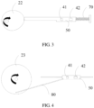
FIG. 3 is a first schematic diagram of transmission of a support according to an embodiment of this application; and -
FIG. 4 is a second schematic diagram of transmission of the support according to an embodiment of this application. - The following clearly and completely describes the technical solutions in the embodiments of this application with reference to the accompanying drawings in the embodiments of this application. Apparently, the described embodiments are some but not all of the embodiments of this application. All other embodiments obtained by a person of ordinary skill in the art based on the embodiments of this application without creative efforts shall fall within the protection scope of this application.
- The terms "first", "second", and the like in this specification and claims of this application are used to distinguish between similar objects instead of describing a specific order or sequence. It should be understood that the data used in this way is interchangeable in appropriate circumstances so that the embodiments of this application can be implemented in other orders than the order illustrated or described herein. In addition, "and/or" in the specification and claims represents at least one of connected objects. Symbol "/" in the specification generally represents an "or" relationship between associated objects.
- As shown in
FIG. 1 to FIG. 4 , embodiments of this application provide an electronic device, including ahousing 10 and a transmission structure, and the housing is provided with an opening (not shown) and a light transmission hole (not shown). - The transmission structure includes a driving member (not shown), a
transmission assembly 20, acamera module 30, and a functional module. The driving member is connected to thecamera module 30, and thecamera module 30 is also connected to the functional module through thetransmission assembly 20. - The
camera module 30 includes at least one camera, and the functional module includes a firstfunctional component 41 and a secondfunctional component 42 arranged along a first direction. In a case that the driving member drives thecamera module 30 to move along a second direction, thetransmission assembly 20 drives the functional module to move along the first direction, and an angle between the first direction and the second direction is greater than 0°. - Under the action of the driving member, the
camera module 30 can move between a first position and a second position, and thetransmission assembly 20 drives the functional module to move between a third position and a fourth position. - In a case that the
camera module 30 is located at the first position, the functional module is located at the third position, thecamera module 30 at least partially passes through the opening and is located outside thehousing 10, and the firstfunctional component 41 is opposite to the light transmission hole. In a case that thecamera module 30 is located at the second position, the functional module is located at the fourth position, thecamera module 30 is hidden in thehousing 10, and the secondfunctional component 42 is opposite to the light transmission hole. - In this implementation manner, the
camera module 30 and the functional module are connected through thetransmission assembly 20, so that when thecamera module 30 driven by the driving member moves along the second direction, the camera module can drive thetransmission assembly 20 to move, further driving the functional module to move along the first direction, so as to achieve link movement of the functional module and thecamera module 30. This way, movement of the functional module is driven by movement of thecamera module 30, so that a fixed position for an existing functional module can be changed, to meet a user's demand for changing a position of the functional module. - By disposing the angle between the first direction and the second direction to be greater than 0°, the
camera module 30 and the functional module can move along different directions, so as to meet the user's demand for position change of the functional module. - When the transmission structure is applied to the electronic device, position change of the
camera module 30 causes position change of the functional module, so that a position of the functional component included in the functional module can be adjusted according to a use scenario. For example, in a case that thecamera module 30 is located at the first position, thecamera module 30 at least partially passes through the opening and is located outside thehousing 10, the functional module is located at the third position, and the firstfunctional component 41 of the functional module is opposite to the light transmission hole, to achieve a relevant function of the firstfunctional component 41. In a case that thecamera module 30 is located at the second position, the functional module is located at the fourth position in thehousing 10 in which thecamera module 30 is hidden, and the secondfunctional component 42 of the functional module is opposite to the light transmission hole, to achieve a relevant function of the secondfunctional component 42. With such arrangement, the firstfunctional component 41 and the secondfunctional component 42 share one light transmission hole, so that the number of light transmission holes opened on thehousing 10 can be effectively reduced, and then a problem of a screen-to-body ratio of the electronic device is small caused by excessively many light transmission holes can be reduced, and then the screen-to-body ratio of the electronic device can be increased. - The first
functional component 41 may be a flashlight, the secondfunctional component 42 may be an optical sensor, and the secondfunctional component 42 may also be another functional component, such as a receiver. - For example, the first
functional component 41 is the flashlight, and the secondfunctional component 42 is the optical sensor for description as follows. - When the
camera module 30 is located at the first position, thecamera module 30 at least partially passes through the opening and is located outside thehousing 10, the functional module is located at the third position, and the flashlight is opposite to the light transmission hole, so that a light filling function of the flashlight can be achieved, shooting requirements of thecamera module 30 can be satisfied, and the optical sensor can be controlled to be in a non-working state, to reduce power consumption of the electronic device. - Correspondingly, in a case that the
camera module 30 is at the second position, the functional module is located at the fourth position in thehousing 10 in which thecamera module 30 is hidden, and the optical sensor is opposite to the light transmission hole, so as to achieve a relevant function of the optical sensor. For example, when the optical sensor is an infrared sensor, an infrared detection function of the electronic device can be achieved, and the flashlight can be controlled to be turned off, that is, in a non-working state, so as to reduce the power consumption of the electronic device. - The
camera module 30 includes a camera assembly and a lifting assembly, the lifting assembly is connected to the camera assembly, the lifting assembly is also connected to the driving member, and the camera assembly is further connected to thetransmission assembly 20. Under the action of the driving member, the lifting assembly drives the camera assembly to move, the camera assembly drives thetransmission assembly 20 to move, and thetransmission assembly 20 drives the functional module to move. - The driving member is configured to drive the
camera module 30 to move between the first position and the second position, that is, to drive thecamera module 30 to switch between a protruding state and a retracting state. - Optionally, the driving member may be a driving motor configured to drive the lifting assembly to move; and the lifting assembly may be a screw drive assembly configured to drive the camera assembly to move.
- The light transmission hole may be a light transmission channel disposed at the
housing 10 or an opening for light transmission. In this application, the light transmission hole is configured to achieve light interaction between the flashlight or the optical sensor and the outside, that is, the flashlight can emit light through the light transmission hole, and the optical sensor can emit light to the outside or receive light from the outside through the light transmission hole. - Optionally, the functional module further includes a
support 50. The firstfunctional component 41 and the secondfunctional component 42 are disposed on thesupport 50. Thetransmission assembly 20 is connected to thesupport 50 and can drive thesupport 50 to move along the first direction. - In this implementation manner, the first
functional component 41 and the secondfunctional component 42 are disposed on thesupport 50 and move together with thesupport 50. Especially, in a case that the firstfunctional component 41 is the flashlight, there is no need to reserve an installation position for the flashlight on thecamera module 30, so that an overall volume of thecamera module 30 can be reduced effectively, and then installation space required for thecamera module 30 can be reduced. In addition, the firstfunctional component 41 and the secondfunctional component 42 share one light transmission hole, so that the number of light transmission holes opened at thehousing 10 can be reduced, and a screen-to-body ratio of the electronic device can be increased to some extent. - In a case that the first
functional component 41 is the flashlight and the secondfunctional component 42 is the optical sensor, when the functional module is at the third position, that is, the flashlight is opposite to the light transmission hole and the optical sensor is hidden in thehousing 10, a working state of the flashlight is controlled, to meet shooting requirements of a user, and the optical sensor is controlled to be in a non-working state, to reduce the power consumption of the electronic device. When the functional module is at the fourth position, that is, the optical sensor is opposite to the light transmission hole and the flashlight is hidden in thehousing 10, the light sensor is controlled to be in a working state, to achieve infrared detection and other functions of the electronic device, and the flashlight is controlled to be off, that is, in a non-working state, to reduce the power consumption of the electronic device. - An angle between the first direction and the second direction is 90°, that is, the first direction and the second direction are perpendicular, and a movement direction of the
camera module 30 is perpendicular to a movement direction of the functional module. For example, the movement direction of thecamera module 30 is a length direction of the electronic device, and the movement direction of the functional module is a width direction of the electronic device. - The
support 50 provided with the flashlight and the optical sensor is located in thehousing 10 and can move in thehousing 10, such as left and right movement. - Moreover, movement of the
support 50 can be implemented through an additional driving assembly, and the drive assembly can drive thetransmission component 20 to move, further driving thesupport 50 to move, so that thesupport 50 can move to the third position or the fourth position, and a relevant function of the electronic device can be achieved. Alternatively, thecamera module 30 and thesupport 50 can be connected by thetransmission assembly 20, so that thesupport 50 can move along with thecamera module 30. For example, when thecamera module 30 moves to the first position, thesupport 50 moves to the third position, so that the electronic device can achieve a relevant function of the firstfunctional component 41. Correspondingly, when thecamera module 20 moves to the second position, thesupport 50 moves to the fourth position, so that the electronic device can achieve a relevant function of the secondfunctional component 42. - The
camera module 30 and thesupport 50 can be connected by thetransmission assembly 20, so that thesupport 50 can move along with thecamera module 30, setting of the driving assembly can be skipped, and then space can be reduced, and layout of a functional component of the electronic device can be optimized. - Optionally, the
transmission assembly 20 includes a first transmission member and a second transmission member. The first transmission member is connected to thecamera module 30, the second transmission member is connected to the functional module, and the first transmission member is in transmission connection with the second transmission member. - In this implementation manner, the second transmission member is connected to the
support 50 of the functional module, and since thecamera module 30 can move between the first position and the second position, thesupport 50 can move between the third position and the fourth position correspondingly. When thecamera module 30 is located at the first position, thesupport 50 is located at the third position, and the firstfunctional component 41 is opposite to the light transmission hole. When thecamera module 30 is located at the second position, thesupport 50 is located at the fourth position, and the secondfunctional component 42 is opposite to the light transmission hole. - In a case that the first
functional component 41 is the flashlight and the secondfunctional device 42 is the optical sensor, thecamera module 30 and thesupport 50 are connected through thetransmission assembly 20, so that thesupport 50 can move along with thecamera module 30. Therefore, synchronous movement of the flashlight and the camera module can be implemented, and then shooting experience of the electronic device can be improved. For example, when thecamera module 30 is at the first position, that is, thecamera module 30 is at least partially located outside thehousing 10 through the opening, so that the shooting function of thecamera module 30 can be achieved. Because thesupport 50 moves together with thecamera module 30, when thecamera module 30 is located at the first position, the flashlight also moves to a position facing the light transmission hole, so that a light filling function of thecamera module 30 can be achieved, and then shooting experience of the electronic device can be improved. - As shown in
FIG. 2 , acamera module 30 is provided with afirst spur rack 31, a first transmission member is a first gear, and the first gear is meshed with thefirst spur rack 31. Therefore, when thecamera module 30 telescopically moves relative to thehousing 10, thefirst spur rack 31 can drive the first gear to rotate, so that thecamera module 30 can drive atransmission assembly 20 to move. - A second transmission member is a
second spur rack 21, and thesecond spur rack 21 is meshed with the first gear, so that thesecond spur rack 21 can move laterally under the action of the first gear. Thesecond spur rack 21 is also fixedly connected to asupport 50, so that thesupport 50 can move laterally together with thesecond spur rack 21, and a flashlight and an optical sensor located on thesupport 50 can move relative to a position of a light transmission hole. In addition, when thesupport 50 moves to a fourth position, the optical sensor is disposed facing the light transmission hole, and the flashlight is hidden in ahousing 10. When thesupport 50 moves to a third position, the flashlight is disposed facing the light transmission hole, and the optical sensor is hidden in thehousing 10. - The
support 50 and thesecond spur rack 21 can be an integral structure, that is, the spur rack can be disposed on thesupport 50 to form the second transmission member. - It should be noted that, to facilitate movement of the
support 50 in thehousing 10, a sliding member slidably connected to thesupport 50 can also be disposed in thehousing 10, and the sliding member may be a sliding rail or a sliding groove disposed in thehousing 10. - When the sliding member is the sliding rail disposed in the
housing 10, a sliding groove matched with the sliding rail can be disposed on thesupport 50. When the sliding member is the sliding groove disposed in thehousing 10, a sliding rail or a sliding block matched with the sliding groove can be disposed on thesupport 50, so that movement of thesupport 50 in thehousing 10 can be improved. - In this implementation manner, a transmission mode for the gear and rack is characterized with a simple structure and small space, so that installation space required for the
transmission assembly 20 can be reduced effectively. - In addition, a position of the
support 50 can also be switched in another transmission mode, such as a cam transmission mode or a slider-crank mechanism. - As shown in
FIG. 3 , a second transmission member may be aneccentric wheel 22. One end of asupport 50 may abut against an outer peripheral surface of theeccentric wheel 22, and the other end of thesupport 50 can be connected to an inner side wall of ahousing 10 through anelastic member 70. Thesupport 50 can move to a third position or a fourth position by using a characteristic of theeccentric wheel 22. - The
elastic member 70 may be a spring, or a silicone tape or the like with an elastic function. - The
housing 10 is provided with a first sliding member (not shown), and thesupport 50 can be slidably connected to the first sliding member, so that thesupport 50 can move to a first position or a second position. - Specifically, the first sliding member may be a first sliding rail disposed in the
housing 10, and thesupport 50 is provided with a first sliding groove matched with the first sliding rail. Alternatively, the first sliding member may be a second sliding groove disposed on thehousing 10, and thesupport 50 is provided with a second sliding rail matched with the second sliding groove. Therefore, movement of thesupport 50 in the cam transmission mode can be implemented. - It should be noted that, in this implementation manner, the first transmission member may be a gear, and can be meshed with a rack on a
camera module 30. Therefore, thecamera module 30 can drive the first transmission member to move. The first transmission member and the second transmission member can be coaxially disposed, so that the second transmission member can move along with the first transmission member, further driving thesupport 50 to move, and thesupport 50 can move to the third position or the fourth position, and a function corresponding to the flashlight or optical sensor of the electronic device can be achieved. - As shown in
FIG. 4 , a second transmission member may be a rotary table 23. The rotary table 23 is connected to asupport 50 through a connectingrod 80, and ahousing 10 is provided with a second sliding member (not shown), and thesupport 50 can be slidably connected to the second sliding member. The connectingrod 80, thesupport 50, the rotary table 23, and the second sliding member form a slider-crank mechanism, so that thesupport 50 can move to a third position or fourth position, and a corresponding function can be achieved. - Specifically, the second sliding member may be a third sliding rail disposed in the
housing 10, and thesupport 50 is provided with a third sliding groove matched with the third sliding rail. Alternatively, the second sliding member may be a fourth sliding groove disposed on thehousing 10, and thesupport 50 is provided with a fourth sliding rail matched with the fourth sliding groove. Therefore, movement of thesupport 50 in a crank-link mechanism mode can be implemented. - It should be noted that, in this implementation manner, the first transmission member may be a gear, and can be meshed with a rack on a
camera module 30, so that thecamera module 30 can drive the first transmission member to move. The first transmission member and the second transmission member can be coaxially disposed, so that the second transmission member can move along with the first transmission member, further driving thesupport 50 to move, and thesupport 50 can move to a first position or a second position, and a function corresponding to the flashlight or optical sensor of the electronic device can be achieved. - It should be noted that the first transmission member and the second transmission member can be two transmission members disposed on a same shaft, so that the second transmission member can move along with the first transmission member.
- The embodiments of this application are described above with reference to the accompanying drawings, but this application is not limited to the foregoing specific implementation manners. The foregoing specific implementation manners are merely schematic instead of restrictive. Under enlightenment of this application, a person of ordinary skills in the art may make many forms without departing from aims and the protection scope of claims of this application, all of which fall within the protection scope of this application.
Claims (10)
- A transmission structure, comprising: a driving member, a transmission assembly, a camera module, and a functional module, wherein the driving member is connected to the camera module, and the camera module is connected to the functional module through the transmission assembly,
wherein the camera module comprises at least one camera, and the functional module comprises a first functional component and a second functional component arranged along a first direction; and in a case that the driving member drives the camera module to move along a second direction, the transmission assembly drives the functional module to move along the first direction, and an angle between the first direction and the second direction is greater than 0°. - The transmission structure according to claim 1, wherein the functional module further comprises a support, and the first functional component and the second functional component are disposed on the support; and
the transmission assembly is connected to the support and can drive the support to move along the first direction. - The transmission structure according to claim 2, wherein the transmission assembly comprises a first transmission member and a second transmission member, wherein the first transmission member is connected to the camera module, the second transmission member is connected to the functional module, and the first transmission member is in transmission connection with the second transmission member.
- The transmission structure according to claim 3, wherein the first transmission member is a first gear, the camera module is provided with a first spur rack, and the first gear is meshed with the first spur rack; and
the second transmission member is a second spur rack, the second spur rack is fixedly connected to the support, and the first gear is further meshed with the second spur rack. - The transmission structure according to claim 3, wherein the transmission structure further comprises a first sliding member, and the support is slidably connected to the first sliding member; and
the second transmission member is an eccentric wheel, one end of the support abuts against an outer peripheral surface of the eccentric wheel, and the other end of the support is connected to a base through an elastic member. - The transmission structure according to claim 3, wherein the transmission structure further comprises a second sliding member, and the support is slidably connected to the second sliding member; and
the second transmission member is a rotary table, the rotary table is connected to the support through a connecting rod, and the rotary table, the connecting rod, the support, and the second sliding member form a slider-crank mechanism. - The transmission structure according to any one of claims 1 to 6, wherein the angle between the first direction and the second direction is 90°.
- An electronic device, comprising a housing and the transmission structure according to any one of claims 1 to 7, wherein the transmission structure is located in the housing, and the housing is provided with an opening and a light transmission hole, the driving member can drive the camera module to move between a first position and a second position, and the transmission assembly drives the functional module to move between a third position and a fourth position,
wherein in a case that the camera module is located at the first position, the functional module is located at the third position, the camera module at least partially passes through the opening and is located outside the housing, and the first functional component is opposite to the light transmission hole; and in a case that the camera module is located at the second position, the functional module is located at the fourth position, the camera module is hidden in the housing, and the second functional component is opposite to the light transmission hole. - The electronic device according to claim 8, wherein the first functional component is a flashlight.
- The electronic device according to claim 9, wherein the second functional component is an optical sensor.
Applications Claiming Priority (2)
| Application Number | Priority Date | Filing Date | Title |
|---|---|---|---|
| CN202010609492.XA CN111756899B (en) | 2020-06-29 | 2020-06-29 | Transmission structure and electronic equipment |
| PCT/CN2021/102045 WO2022001814A1 (en) | 2020-06-29 | 2021-06-24 | Transmission structure and electronic device |
Publications (3)
| Publication Number | Publication Date |
|---|---|
| EP4175263A1 true EP4175263A1 (en) | 2023-05-03 |
| EP4175263A4 EP4175263A4 (en) | 2023-12-27 |
| EP4175263B1 EP4175263B1 (en) | 2025-06-18 |
Family
ID=72678261
Family Applications (1)
| Application Number | Title | Priority Date | Filing Date |
|---|---|---|---|
| EP21832980.3A Active EP4175263B1 (en) | 2020-06-29 | 2021-06-24 | Transmission structure and electronic device |
Country Status (7)
| Country | Link |
|---|---|
| US (1) | US12432291B2 (en) |
| EP (1) | EP4175263B1 (en) |
| JP (1) | JP7486620B2 (en) |
| KR (1) | KR102776974B1 (en) |
| CN (1) | CN111756899B (en) |
| ES (1) | ES3035457T3 (en) |
| WO (1) | WO2022001814A1 (en) |
Families Citing this family (3)
| Publication number | Priority date | Publication date | Assignee | Title |
|---|---|---|---|---|
| CN111756899B (en) | 2020-06-29 | 2021-06-15 | 维沃移动通信有限公司 | Transmission structure and electronic equipment |
| CN112963707B (en) * | 2021-01-20 | 2022-08-30 | 浙江智马达智能科技有限公司 | Over-and-under type camera structure and vehicle |
| WO2022213842A1 (en) * | 2021-04-08 | 2022-10-13 | 华为技术有限公司 | Electronic device and camera assembly |
Family Cites Families (27)
| Publication number | Priority date | Publication date | Assignee | Title |
|---|---|---|---|---|
| JP2003259166A (en) * | 2002-02-28 | 2003-09-12 | Matsushita Electric Ind Co Ltd | Mobile phone |
| KR100583868B1 (en) * | 2003-12-11 | 2006-05-26 | 주식회사 팬택앤큐리텔 | Flash unit with adjustable flash angle |
| CN207530918U (en) * | 2017-10-30 | 2018-06-22 | 维沃移动通信有限公司 | Electronic equipment |
| KR102493579B1 (en) * | 2018-01-08 | 2023-01-31 | 삼성전자주식회사 | Electronic device including camera and method for controlling the electronic device |
| CN110324448B (en) * | 2018-03-31 | 2021-06-15 | Oppo广东移动通信有限公司 | Electronic device and control method of electronic device |
| CN108833621A (en) * | 2018-06-06 | 2018-11-16 | 宇龙计算机通信科技(深圳)有限公司 | Mobile terminal and its control method |
| CN108600464B (en) * | 2018-06-19 | 2020-05-19 | Oppo广东移动通信有限公司 | Electronic equipment and its function module control method |
| CN108989500B (en) * | 2018-07-27 | 2021-03-02 | 维沃移动通信有限公司 | A drive module, terminal and control method |
| CN209170429U (en) * | 2018-11-12 | 2019-07-26 | 维沃移动通信有限公司 | Mobile terminal |
| KR102108650B1 (en) * | 2018-11-21 | 2020-05-07 | 이민상 | Mobile Communication Terminal having Top and Bottom Camera Module |
| CN111225085A (en) * | 2018-11-26 | 2020-06-02 | 华为技术有限公司 | mobile terminal |
| CN209787206U (en) * | 2018-11-30 | 2019-12-13 | Oppo广东移动通信有限公司 | Transmission mechanism, drive mechanism assembly, installation drive assembly and mobile terminal |
| CN111294429A (en) * | 2018-12-10 | 2020-06-16 | Oppo广东移动通信有限公司 | Electronic device |
| CN110099147B (en) | 2019-03-27 | 2020-11-06 | 华为技术有限公司 | Communication device |
| CN109922245B (en) * | 2019-03-29 | 2021-05-18 | 维沃移动通信(杭州)有限公司 | A camera assembly and terminal equipment |
| KR102789170B1 (en) * | 2019-06-21 | 2025-04-03 | 삼성전자주식회사 | Electronic device and method including a sub display |
| CN110430295A (en) * | 2019-07-10 | 2019-11-08 | 华为技术有限公司 | an electronic device |
| CN110445914B (en) * | 2019-07-31 | 2021-07-30 | 荣耀终端有限公司 | a terminal device |
| CN210041899U (en) * | 2019-08-23 | 2020-02-07 | 维沃移动通信有限公司 | a mobile terminal |
| CN110519494B (en) * | 2019-08-23 | 2022-02-01 | 维沃移动通信(杭州)有限公司 | Optical module and electronic equipment |
| CN110557541A (en) * | 2019-09-23 | 2019-12-10 | 维沃移动通信(杭州)有限公司 | electronic apparatus, device control method, and computer-readable storage medium |
| CN110650229A (en) * | 2019-09-26 | 2020-01-03 | 华勤通讯技术有限公司 | Liftable camera subassembly and contain its intelligent terminal equipment |
| CN111182097B (en) * | 2019-12-23 | 2021-08-20 | 诚瑞光学(常州)股份有限公司 | Image pickup device, electronic device, and method of using the electronic device |
| CN113497853B (en) * | 2020-04-02 | 2023-11-17 | 华为技术有限公司 | Control methods for electronic equipment and movable components |
| CN111477104A (en) * | 2020-05-29 | 2020-07-31 | 厦门天马微电子有限公司 | Display device and electronic equipment |
| CN111726500B (en) * | 2020-06-24 | 2021-12-03 | 维沃移动通信(杭州)有限公司 | Image acquisition method and device, electronic equipment and readable storage medium |
| CN111756899B (en) * | 2020-06-29 | 2021-06-15 | 维沃移动通信有限公司 | Transmission structure and electronic equipment |
-
2020
- 2020-06-29 CN CN202010609492.XA patent/CN111756899B/en active Active
-
2021
- 2021-06-24 KR KR1020237001598A patent/KR102776974B1/en active Active
- 2021-06-24 EP EP21832980.3A patent/EP4175263B1/en active Active
- 2021-06-24 ES ES21832980T patent/ES3035457T3/en active Active
- 2021-06-24 WO PCT/CN2021/102045 patent/WO2022001814A1/en not_active Ceased
- 2021-06-24 JP JP2022581576A patent/JP7486620B2/en active Active
-
2022
- 2022-12-20 US US18/068,890 patent/US12432291B2/en active Active
Also Published As
| Publication number | Publication date |
|---|---|
| US12432291B2 (en) | 2025-09-30 |
| EP4175263B1 (en) | 2025-06-18 |
| ES3035457T3 (en) | 2025-09-03 |
| WO2022001814A1 (en) | 2022-01-06 |
| CN111756899B (en) | 2021-06-15 |
| KR20230022253A (en) | 2023-02-14 |
| EP4175263A4 (en) | 2023-12-27 |
| US20230127253A1 (en) | 2023-04-27 |
| CN111756899A (en) | 2020-10-09 |
| JP7486620B2 (en) | 2024-05-17 |
| KR102776974B1 (en) | 2025-03-05 |
| JP2023531829A (en) | 2023-07-25 |
Similar Documents
| Publication | Publication Date | Title |
|---|---|---|
| US12432291B2 (en) | Transmission structure and electronic device | |
| CN112291954B (en) | Electronic device | |
| EP3789821B1 (en) | Mobile terminal with extendible camera | |
| WO2020156140A1 (en) | Electronic device | |
| CN110062146B (en) | Terminal Equipment | |
| US11622457B2 (en) | Synchronous transmission pivot shaft device | |
| CN109005263B (en) | Mobile terminal | |
| CN113194180A (en) | Electronic device | |
| CN113194178B (en) | Electronic equipment | |
| CN115941822B (en) | Electronic equipment, locking mechanism | |
| EP4325817A1 (en) | Electronic device | |
| CN109862248A (en) | Terminal Equipment | |
| WO2020221352A1 (en) | Terminal device | |
| EP2296354B1 (en) | Handheld electronic device | |
| WO2020259102A1 (en) | Wrist terminal apparatus | |
| CN111140738B (en) | Driving mechanism and electronic device | |
| CN109995905B (en) | Functional module, electronic device and control method of electronic device | |
| CN110392139B (en) | electronic device | |
| KR101296335B1 (en) | Hinge device of folding type mobile phone | |
| CN110518741A (en) | Electronic equipment | |
| CN110324469B (en) | mobile terminal | |
| CN220711560U (en) | Camera device and electronic equipment | |
| CN113055569A (en) | Electronic device | |
| EP4497957A1 (en) | Rotating shaft mechanism and electronic device | |
| CN110300200A (en) | Terminal device |
Legal Events
| Date | Code | Title | Description |
|---|---|---|---|
| STAA | Information on the status of an ep patent application or granted ep patent |
Free format text: STATUS: THE INTERNATIONAL PUBLICATION HAS BEEN MADE |
|
| PUAI | Public reference made under article 153(3) epc to a published international application that has entered the european phase |
Free format text: ORIGINAL CODE: 0009012 |
|
| STAA | Information on the status of an ep patent application or granted ep patent |
Free format text: STATUS: REQUEST FOR EXAMINATION WAS MADE |
|
| 17P | Request for examination filed |
Effective date: 20230103 |
|
| AK | Designated contracting states |
Kind code of ref document: A1 Designated state(s): AL AT BE BG CH CY CZ DE DK EE ES FI FR GB GR HR HU IE IS IT LI LT LU LV MC MK MT NL NO PL PT RO RS SE SI SK SM TR |
|
| DAV | Request for validation of the european patent (deleted) | ||
| DAX | Request for extension of the european patent (deleted) | ||
| A4 | Supplementary search report drawn up and despatched |
Effective date: 20231128 |
|
| RIC1 | Information provided on ipc code assigned before grant |
Ipc: G03B 30/00 20210101ALI20231122BHEP Ipc: G03B 17/04 20210101ALI20231122BHEP Ipc: G03B 11/04 20210101ALI20231122BHEP Ipc: H04M 1/02 20060101AFI20231122BHEP |
|
| GRAP | Despatch of communication of intention to grant a patent |
Free format text: ORIGINAL CODE: EPIDOSNIGR1 |
|
| STAA | Information on the status of an ep patent application or granted ep patent |
Free format text: STATUS: GRANT OF PATENT IS INTENDED |
|
| INTG | Intention to grant announced |
Effective date: 20250327 |
|
| GRAS | Grant fee paid |
Free format text: ORIGINAL CODE: EPIDOSNIGR3 |
|
| GRAA | (expected) grant |
Free format text: ORIGINAL CODE: 0009210 |
|
| STAA | Information on the status of an ep patent application or granted ep patent |
Free format text: STATUS: THE PATENT HAS BEEN GRANTED |
|
| AK | Designated contracting states |
Kind code of ref document: B1 Designated state(s): AL AT BE BG CH CY CZ DE DK EE ES FI FR GB GR HR HU IE IS IT LI LT LU LV MC MK MT NL NO PL PT RO RS SE SI SK SM TR |
|
| REG | Reference to a national code |
Ref country code: GB Ref legal event code: FG4D |
|
| REG | Reference to a national code |
Ref country code: CH Ref legal event code: EP |
|
| PGFP | Annual fee paid to national office [announced via postgrant information from national office to epo] |
Ref country code: GB Payment date: 20250626 Year of fee payment: 5 |
|
| REG | Reference to a national code |
Ref country code: DE Ref legal event code: R096 Ref document number: 602021032570 Country of ref document: DE |
|
| REG | Reference to a national code |
Ref country code: CH Ref legal event code: EP |
|
| REG | Reference to a national code |
Ref country code: IE Ref legal event code: FG4D |
|
| PGFP | Annual fee paid to national office [announced via postgrant information from national office to epo] |
Ref country code: AT Payment date: 20250721 Year of fee payment: 5 |
|
| REG | Reference to a national code |
Ref country code: NL Ref legal event code: FP |
|
| PGFP | Annual fee paid to national office [announced via postgrant information from national office to epo] |
Ref country code: NL Payment date: 20250704 Year of fee payment: 5 |
|
| REG | Reference to a national code |
Ref country code: ES Ref legal event code: FG2A Ref document number: 3035457 Country of ref document: ES Kind code of ref document: T3 Effective date: 20250903 |
|
| PG25 | Lapsed in a contracting state [announced via postgrant information from national office to epo] |
Ref country code: FI Free format text: LAPSE BECAUSE OF FAILURE TO SUBMIT A TRANSLATION OF THE DESCRIPTION OR TO PAY THE FEE WITHIN THE PRESCRIBED TIME-LIMIT Effective date: 20250618 |
|
| PGFP | Annual fee paid to national office [announced via postgrant information from national office to epo] |
Ref country code: ES Payment date: 20250729 Year of fee payment: 5 |
|
| PGFP | Annual fee paid to national office [announced via postgrant information from national office to epo] |
Ref country code: DE Payment date: 20250702 Year of fee payment: 5 |
|
| REG | Reference to a national code |
Ref country code: LT Ref legal event code: MG9D |
|
| PG25 | Lapsed in a contracting state [announced via postgrant information from national office to epo] |
Ref country code: NO Free format text: LAPSE BECAUSE OF FAILURE TO SUBMIT A TRANSLATION OF THE DESCRIPTION OR TO PAY THE FEE WITHIN THE PRESCRIBED TIME-LIMIT Effective date: 20250918 Ref country code: GR Free format text: LAPSE BECAUSE OF FAILURE TO SUBMIT A TRANSLATION OF THE DESCRIPTION OR TO PAY THE FEE WITHIN THE PRESCRIBED TIME-LIMIT Effective date: 20250919 |
|
| PG25 | Lapsed in a contracting state [announced via postgrant information from national office to epo] |
Ref country code: BG Free format text: LAPSE BECAUSE OF FAILURE TO SUBMIT A TRANSLATION OF THE DESCRIPTION OR TO PAY THE FEE WITHIN THE PRESCRIBED TIME-LIMIT Effective date: 20250618 |
|
| PG25 | Lapsed in a contracting state [announced via postgrant information from national office to epo] |
Ref country code: HR Free format text: LAPSE BECAUSE OF FAILURE TO SUBMIT A TRANSLATION OF THE DESCRIPTION OR TO PAY THE FEE WITHIN THE PRESCRIBED TIME-LIMIT Effective date: 20250618 |
|
| PGFP | Annual fee paid to national office [announced via postgrant information from national office to epo] |
Ref country code: FR Payment date: 20250715 Year of fee payment: 5 |
|
| PG25 | Lapsed in a contracting state [announced via postgrant information from national office to epo] |
Ref country code: RS Free format text: LAPSE BECAUSE OF FAILURE TO SUBMIT A TRANSLATION OF THE DESCRIPTION OR TO PAY THE FEE WITHIN THE PRESCRIBED TIME-LIMIT Effective date: 20250918 |
|
| PG25 | Lapsed in a contracting state [announced via postgrant information from national office to epo] |
Ref country code: LV Free format text: LAPSE BECAUSE OF FAILURE TO SUBMIT A TRANSLATION OF THE DESCRIPTION OR TO PAY THE FEE WITHIN THE PRESCRIBED TIME-LIMIT Effective date: 20250618 |
|
| PG25 | Lapsed in a contracting state [announced via postgrant information from national office to epo] |
Ref country code: PT Free format text: LAPSE BECAUSE OF FAILURE TO SUBMIT A TRANSLATION OF THE DESCRIPTION OR TO PAY THE FEE WITHIN THE PRESCRIBED TIME-LIMIT Effective date: 20251020 |
|
| REG | Reference to a national code |
Ref country code: AT Ref legal event code: MK05 Ref document number: 1805263 Country of ref document: AT Kind code of ref document: T Effective date: 20250618 |
|
| PG25 | Lapsed in a contracting state [announced via postgrant information from national office to epo] |
Ref country code: IS Free format text: LAPSE BECAUSE OF FAILURE TO SUBMIT A TRANSLATION OF THE DESCRIPTION OR TO PAY THE FEE WITHIN THE PRESCRIBED TIME-LIMIT Effective date: 20251018 |
|
| PG25 | Lapsed in a contracting state [announced via postgrant information from national office to epo] |
Ref country code: AT Free format text: LAPSE BECAUSE OF FAILURE TO SUBMIT A TRANSLATION OF THE DESCRIPTION OR TO PAY THE FEE WITHIN THE PRESCRIBED TIME-LIMIT Effective date: 20250618 Ref country code: SM Free format text: LAPSE BECAUSE OF FAILURE TO SUBMIT A TRANSLATION OF THE DESCRIPTION OR TO PAY THE FEE WITHIN THE PRESCRIBED TIME-LIMIT Effective date: 20250618 |
|
| PG25 | Lapsed in a contracting state [announced via postgrant information from national office to epo] |
Ref country code: CZ Free format text: LAPSE BECAUSE OF FAILURE TO SUBMIT A TRANSLATION OF THE DESCRIPTION OR TO PAY THE FEE WITHIN THE PRESCRIBED TIME-LIMIT Effective date: 20250618 |
|
| PG25 | Lapsed in a contracting state [announced via postgrant information from national office to epo] |
Ref country code: PL Free format text: LAPSE BECAUSE OF FAILURE TO SUBMIT A TRANSLATION OF THE DESCRIPTION OR TO PAY THE FEE WITHIN THE PRESCRIBED TIME-LIMIT Effective date: 20250618 |
|
| PG25 | Lapsed in a contracting state [announced via postgrant information from national office to epo] |
Ref country code: EE Free format text: LAPSE BECAUSE OF FAILURE TO SUBMIT A TRANSLATION OF THE DESCRIPTION OR TO PAY THE FEE WITHIN THE PRESCRIBED TIME-LIMIT Effective date: 20250618 |
|
| PG25 | Lapsed in a contracting state [announced via postgrant information from national office to epo] |
Ref country code: SK Free format text: LAPSE BECAUSE OF FAILURE TO SUBMIT A TRANSLATION OF THE DESCRIPTION OR TO PAY THE FEE WITHIN THE PRESCRIBED TIME-LIMIT Effective date: 20250618 |
|
| REG | Reference to a national code |
Ref country code: CH Ref legal event code: H13 Free format text: ST27 STATUS EVENT CODE: U-0-0-H10-H13 (AS PROVIDED BY THE NATIONAL OFFICE) Effective date: 20260127 |
|
| PG25 | Lapsed in a contracting state [announced via postgrant information from national office to epo] |
Ref country code: LU Free format text: LAPSE BECAUSE OF NON-PAYMENT OF DUE FEES Effective date: 20250624 |
|
| REG | Reference to a national code |
Ref country code: BE Ref legal event code: MM Effective date: 20250630 |
|
| PG25 | Lapsed in a contracting state [announced via postgrant information from national office to epo] |
Ref country code: RO Free format text: LAPSE BECAUSE OF FAILURE TO SUBMIT A TRANSLATION OF THE DESCRIPTION OR TO PAY THE FEE WITHIN THE PRESCRIBED TIME-LIMIT Effective date: 20250618 |
|
| REG | Reference to a national code |
Ref country code: DE Ref legal event code: R097 Ref document number: 602021032570 Country of ref document: DE |
|
| PG25 | Lapsed in a contracting state [announced via postgrant information from national office to epo] |
Ref country code: MC Free format text: LAPSE BECAUSE OF FAILURE TO SUBMIT A TRANSLATION OF THE DESCRIPTION OR TO PAY THE FEE WITHIN THE PRESCRIBED TIME-LIMIT Effective date: 20250618 |
|
| PG25 | Lapsed in a contracting state [announced via postgrant information from national office to epo] |
Ref country code: IE Free format text: LAPSE BECAUSE OF NON-PAYMENT OF DUE FEES Effective date: 20250624 Ref country code: DK Free format text: LAPSE BECAUSE OF FAILURE TO SUBMIT A TRANSLATION OF THE DESCRIPTION OR TO PAY THE FEE WITHIN THE PRESCRIBED TIME-LIMIT Effective date: 20250618 |
|
| PG25 | Lapsed in a contracting state [announced via postgrant information from national office to epo] |
Ref country code: IT Free format text: LAPSE BECAUSE OF NON-PAYMENT OF DUE FEES Effective date: 20250624 Ref country code: BE Free format text: LAPSE BECAUSE OF NON-PAYMENT OF DUE FEES Effective date: 20250630 |
|
| PG25 | Lapsed in a contracting state [announced via postgrant information from national office to epo] |
Ref country code: CH Free format text: LAPSE BECAUSE OF NON-PAYMENT OF DUE FEES Effective date: 20250630 |
|
| PLBE | No opposition filed within time limit |
Free format text: ORIGINAL CODE: 0009261 |
|
| STAA | Information on the status of an ep patent application or granted ep patent |
Free format text: STATUS: NO OPPOSITION FILED WITHIN TIME LIMIT |
|
| REG | Reference to a national code |
Ref country code: CH Ref legal event code: L10 Free format text: ST27 STATUS EVENT CODE: U-0-0-L10-L00 (AS PROVIDED BY THE NATIONAL OFFICE) Effective date: 20260430 |