EP4174801B1 - Image capturing method - Google Patents
Image capturing method Download PDFInfo
- Publication number
- EP4174801B1 EP4174801B1 EP21205976.0A EP21205976A EP4174801B1 EP 4174801 B1 EP4174801 B1 EP 4174801B1 EP 21205976 A EP21205976 A EP 21205976A EP 4174801 B1 EP4174801 B1 EP 4174801B1
- Authority
- EP
- European Patent Office
- Prior art keywords
- image capturing
- area
- license plate
- image
- capturing method
- Prior art date
- Legal status (The legal status is an assumption and is not a legal conclusion. Google has not performed a legal analysis and makes no representation as to the accuracy of the status listed.)
- Active
Links
Images


Classifications
-
- G—PHYSICS
- G06—COMPUTING OR CALCULATING; COUNTING
- G06V—IMAGE OR VIDEO RECOGNITION OR UNDERSTANDING
- G06V20/00—Scenes; Scene-specific elements
- G06V20/60—Type of objects
- G06V20/62—Text, e.g. of license plates, overlay texts or captions on TV images
- G06V20/625—License plates
Definitions
- the present disclosure relates to an image capturing method.
- Shared motor vehicles provide a lot of convenience for the people.
- the rent-and-return feature combined with electric motor vehicles allows users to move more maneuverable and have a longer travel distance than shared bicycles, while also taking into account the environmental protection effect.
- the shared motor vehicles are also often disputed because of the rental and return feature. For example, after returning a motor vehicle, the user will receive a ticket due to the movement of the motor vehicle by others. The user will have a poor user experience due to the failure to provide proof of returning the motor vehicle.
- JP 2007 086 858 A discloses an image capturing method, comprising: providing an image capturing area on a display screen of a user device; providing an indication area in the image capturing area; marking a license plate after identifying the license plate based on at least one feature in the image capturing area. Another method is disclosed by US 2018 / 300 578 A1 .
- An aspect of the disclosure is to provide an image capturing method that can efficiently solve the aforementioned problems.
- the indication area provided in the image capturing area can guide the user to obtain an image with a specific composition to ensure that the image is saved with specific information.
- the safety of the user in the process of capturing images can be improved.
- marking the license plate the user's recognition of the license plate can be improved, thereby reducing the time for the user to capture images.
- the stability of capturing the image can be increased to make the obtained image clearer.
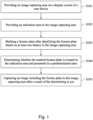
- Fig. 1 is a flow chart of an image capturing method according to an embodiment of the present disclosure.
- Figs. 2 to 5 are schematic diagrams respectively showing different steps of the image capturing method according to an embodiment of the present disclosure.
- the image capturing method mainly includes step S101 to step S105.
- Step S101 providing an image capturing area 111 on a display screen 110 of a user device 100.
- Step S102 providing an indication area 112 in the image capturing area 111.
- Step S103 marking a license plate 900 after identifying the license plate 900 based on at least one feature in the image capturing area 111.
- Step S104 determining whether the marked license plate 900 is located in the indication area 112 and presented in a predetermined ratio.
- Step S105 capturing an image including the license plate 900 in the image capturing area 111 after a result of the determining is yes.
- the user device 100 is, for example, a smart phone, but the disclosure is not limited in this regard.
- the user device 100 further includes a camera module (not shown).
- the camera module is configured to take pictures of the surroundings of the user device 100.
- the display screen 110 is configured to display the scene shot by the camera module in the image capturing area 111.
- a scene of a vehicle with a license plate 900 is taken as an example.
- the at least one feature includes English letters and numbers with a predetermined format/number of characters and a predetermined aspect ratio of license plate, but the disclosure is not limited in this regard.
- the predetermined format may include a font format and/or an arrangement order format of the English letters and numbers of license plates of various types of traffic vehicles that comply with local regulations, but the disclosure is not limited in this regard.
- the predetermined aspect ratio of license plate may be a specific range of aspect ratios of the license plates of the various traffic vehicles that comply with local regulations.
- the aspect ratio of the license plate 900 displayed in the image capturing area 111 does not meet the predetermined aspect ratio of license plate, and the license plate 900 is not recognized or marked because it does not have the aforementioned at least one feature.
- the image capturing method further includes step S 106a.
- Step S106a further providing a guidance information display area 114 in the image capturing area 111.
- the guidance information display area 114 is indicated by a dotted line.
- the guidance information display area 114 provides a dialog box.
- the guidance information display area 114 may provide the dialog box 114a and display a guide description in the dialog box 114a.
- the dialog box 114a may display the guide description "Please face the license plate and make sure that the license plate is in the area below!, but the disclosure is not limited in this regard.
- the foregoing guide description may indicate the user to move the user device 100 so that the camera module can shoot from the rear of the vehicle, so that the license plate 900 can be recognized in the image capturing area 111.
- the image capturing method further includes step S106b.
- Step S106b when the marked license plate 900 is not located in the indication area 112 and/or is not presented in the predetermined ratio, providing a guide description in the guidance information display area 114.
- the guidance information display area 114 may provide the dialog box 114a and display a guide description in the dialog box 114a.
- the dialog box 114a may display the guide description "Please make sure the license plate is in the area below!, but the disclosure is not limited in this regard.
- the aforementioned guide description may indicate the user to move the user device 100 to adjust the viewing angle of the camera module, so that the marked license plate 900 can be located in the indication area 112.
- the guidance information display area 114 may provide the dialog box 114a and display a guide description in the dialog box 114a.
- the dialog box 114a may display the guide description "Please come closer!”, but the disclosure is not limited in this regard.
- the aforementioned guide description may indicate the user to move the user device 100 to adjust the distance between the camera module and the license plate 900, so that the marked license plate 900 is displayed in the indication area 112 in the predetermined ratio. In this way, the personal safety problem caused by the user being too close to the lane can be avoided.
- the predetermined ratio is a ratio of the license plate 900 located in the indication area 112 to the image capturing area 111 (for example, a width ratio or an area ratio), but the disclosure is not limited in this regard.
- the width ratio of the license plate 900 to the image capturing area 111 is between 1/4 and 3/4, but the disclosure is not limited in this regard.
- the image capturing method further includes step S103a.
- Step S103a providing a marking area 115 in the image capturing area 111 111 to mark the license plate 900.
- the indication area 112 may be marked by a frame formed by a solid line, and the marking area 115 may be marked by a frame formed by a dotted line, so as to improve the clarity of identification when the user operates the user device 100, but the disclosure is not limited in this regard. In practical applications, the indication area 112 and the marking area 115 may also be marked with different types or colors of frame or color blocks.
- the image capturing method further includes step S106c.
- Step S106c when the marked license plate 900 is located in the indication area 112 and presented in the predetermined ratio, providing a timing indicator 114b in the guidance information display area 114.
- the guidance information display area 114 may provide the timing indicator 114b.
- the timing indicator 114b may be presented in the form of numbers, but the disclosure is not limited in this regard.
- the timing indicator 114b may count down from 3, but the disclosure is not limited in this regard.
- step S105 further includes step S105a.
- Step S105a capturing the image at an end of countdown of the timing indicator 114b if the result of the determining is yes.
- the image presented in the image capturing area 111 is the image captured when the countdown of the timing indicator 114b ends.
- the image capturing method further includes step S107.
- Step S107 further providing an operation area 113 on the display screen 110, in which the operation area 113 and the image capturing area 111 are side by side.
- the image capturing area 111 and the operation area 113 are arranged side by side on the display screen 110 up and down, but the disclosure is not limited in this regard.
- the operation area 113 may provide a shooting virtual button 113a and a flash virtual button 113b, but the disclosure is not limited in this regard.
- the shooting virtual button 113a may provide a function of manually capturing an image for a user who does not need to automatically capture the image based on the image capturing method of the present disclosure.
- the flash virtual button 113b may provide a function for the user to select whether to enable the camera module to turn on the flash when capturing the image.
- the operation area 113 may provide a re-shooting virtual button 113c and an upload virtual button 113d, but the disclosure is not limited in this regard.
- the re-shooting virtual button 113c may provide the user with a function of re-shooting an image.
- the upload virtual button 113d may provide the user with a function of uploading the captured image to a cloud storage device.
- the satellite positioning information of the location of the captured image can be sent at the same time to more clearly record the parking position of the vehicle.
- the clear location of the vehicle can help the user find the vehicle more quickly the next time it is used, thereby saving the user the time to find the vehicle.
- the image capturing method of the present disclosure can be combined with a vehicle return system, so as to assist the user to save the return record by capturing images and thus reduce return disputes.
- the image capturing method disclosed in the present disclosure can prevent the user from paying additional rental fees or paying a ticket because the vehicle is moved by others after returning the vehicle.
- the indication area provided in the image capturing area can guide the user to obtain an image with a specific composition to ensure that the image is saved with specific information.
- the safety of the user in the process of capturing images can be improved.
- marking the license plate the user's recognition of the license plate can be improved, thereby reducing the time for the user to capture images.
- the stability of capturing the image can be increased to make the obtained image clearer.
Landscapes
- Engineering & Computer Science (AREA)
- Physics & Mathematics (AREA)
- General Physics & Mathematics (AREA)
- Multimedia (AREA)
- Theoretical Computer Science (AREA)
- Traffic Control Systems (AREA)
Description
- The present disclosure relates to an image capturing method.
- Shared motor vehicles provide a lot of convenience for the people. The rent-and-return feature combined with electric motor vehicles allows users to move more maneuverable and have a longer travel distance than shared bicycles, while also taking into account the environmental protection effect.
- However, the shared motor vehicles are also often disputed because of the rental and return feature. For example, after returning a motor vehicle, the user will receive a ticket due to the movement of the motor vehicle by others. The user will have a poor user experience due to the failure to provide proof of returning the motor vehicle.
- Accordingly, how to provide an image capturing method to solve the aforementioned problems becomes an important issue to be solved by those in the industry.
JP 2007 086 858 A US 2018 / 300 578 A1 . - An aspect of the disclosure is to provide an image capturing method that can efficiently solve the aforementioned problems.
- According to the present invention, an image capturing method according to claim 1 is provided. The dependent claims show some examples thereof
- Accordingly, in the image capturing method of the present disclosure, the indication area provided in the image capturing area can guide the user to obtain an image with a specific composition to ensure that the image is saved with specific information. By guiding the user to display the license plate in the indication area in a predetermined ratio, the safety of the user in the process of capturing images can be improved. By marking the license plate, the user's recognition of the license plate can be improved, thereby reducing the time for the user to capture images. By limiting that the image is captured only when the marked license plate is present in the indication area in the predetermined ratio for a predetermined period of time, the stability of capturing the image can be increased to make the obtained image clearer. By combining the image capturing method with a vehicle return system, the user can be assisted to save the return record by capturing images, so as to reduce return disputes.
- It is to be understood that both the foregoing general description and the following detailed description are by examples, and are intended to provide further explanation of the disclosure as claimed.
- The disclosure can be more fully understood by reading the following detailed description of the embodiment, with reference made to the accompanying drawings as follows:
-
Fig. 1 is a flow chart of an image capturing method according to an embodiment of the present disclosure; -
Fig. 2 is a schematic diagram showing one of steps of the image capturing method according to an embodiment of the present disclosure; -
Fig. 3 is a schematic diagram showing one of steps of the image capturing method according to an embodiment of the present disclosure; -
Fig. 4 is a schematic diagram showing one of steps of the image capturing method according to an embodiment of the present disclosure; and -
Fig. 5 is a schematic diagram showing one of steps of the image capturing method according to an embodiment of the present disclosure. - Reference will now be made in detail to the present embodiments of the disclosure, examples of which are illustrated in the accompanying drawings. Wherever possible, the same reference numbers are used in the drawings and the description to refer to the same or like parts. However, specific structural and functional details disclosed herein are merely representative for purposes of describing example embodiments, and thus may be embodied in many alternate forms and should not be construed as limited to only example embodiments set forth herein. Therefore, it should be understood that there is no intent to limit example embodiments to the particular forms disclosed, but on the contrary, example embodiments are to cover all modifications, equivalents, and alternatives falling within the scope of the disclosure.
- Reference is made to
Fig. 1 with reference toFigs. 2 to 5 together.Fig. 1 is a flow chart of an image capturing method according to an embodiment of the present disclosure.Figs. 2 to 5 are schematic diagrams respectively showing different steps of the image capturing method according to an embodiment of the present disclosure. As shown inFig. 1 , in the present disclosure, the image capturing method mainly includes step S101 to step S105. - Step S101: providing an
image capturing area 111 on adisplay screen 110 of auser device 100. - Step S102: providing an
indication area 112 in theimage capturing area 111. - Step S103: marking a
license plate 900 after identifying thelicense plate 900 based on at least one feature in theimage capturing area 111. - Step S104: determining whether the
marked license plate 900 is located in theindication area 112 and presented in a predetermined ratio. - Step S105: capturing an image including the
license plate 900 in theimage capturing area 111 after a result of the determining is yes. - In some embodiments, the
user device 100 is, for example, a smart phone, but the disclosure is not limited in this regard. In some embodiments, theuser device 100 further includes a camera module (not shown). The camera module is configured to take pictures of the surroundings of theuser device 100. Thedisplay screen 110 is configured to display the scene shot by the camera module in theimage capturing area 111. - As shown in
Figs. 2 to 5 , in the present embodiment, in theimage capturing area 111, a scene of a vehicle with alicense plate 900 is taken as an example. - In some embodiments, the at least one feature includes English letters and numbers with a predetermined format/number of characters and a predetermined aspect ratio of license plate, but the disclosure is not limited in this regard. For example, the predetermined format may include a font format and/or an arrangement order format of the English letters and numbers of license plates of various types of traffic vehicles that comply with local regulations, but the disclosure is not limited in this regard. For example, the predetermined aspect ratio of license plate may be a specific range of aspect ratios of the license plates of the various traffic vehicles that comply with local regulations.
- As shown in
Fig. 2 , in the present embodiment, since the camera module does not shot directly behind the vehicle, the aspect ratio of thelicense plate 900 displayed in theimage capturing area 111 does not meet the predetermined aspect ratio of license plate, and thelicense plate 900 is not recognized or marked because it does not have the aforementioned at least one feature. - In some embodiments, the image capturing method further includes step S 106a.
- Step S106a: further providing a guidance
information display area 114 in theimage capturing area 111. - As shown in
Fig. 2 , in the present embodiment, the guidanceinformation display area 114 is indicated by a dotted line. The guidanceinformation display area 114 provides a dialog box. When step S103 is performed according to the image capturing method of the present disclosure but thelicense plate 900 is not recognized in theimage capturing area 111, the guidanceinformation display area 114 may provide thedialog box 114a and display a guide description in thedialog box 114a. For example, thedialog box 114a may display the guide description "Please face the license plate and make sure that the license plate is in the area below!", but the disclosure is not limited in this regard. The foregoing guide description may indicate the user to move theuser device 100 so that the camera module can shoot from the rear of the vehicle, so that thelicense plate 900 can be recognized in theimage capturing area 111. - In some embodiments, the image capturing method further includes step S106b.
- Step S106b: when the marked
license plate 900 is not located in theindication area 112 and/or is not presented in the predetermined ratio, providing a guide description in the guidanceinformation display area 114. - As shown in
Fig. 3 , in the present embodiment, when step S104 is performed according to the image capturing method of the present disclosure but it is found that the markedlicense plate 900 is not located in theindication area 112, the guidanceinformation display area 114 may provide thedialog box 114a and display a guide description in thedialog box 114a. For example, thedialog box 114a may display the guide description "Please make sure the license plate is in the area below!", but the disclosure is not limited in this regard. The aforementioned guide description may indicate the user to move theuser device 100 to adjust the viewing angle of the camera module, so that the markedlicense plate 900 can be located in theindication area 112. - In some embodiments, when step S104 is performed according to the image capturing method of the present disclosure but it is found that the marked
license plate 900 is not presented in the predetermined ratio, the guidanceinformation display area 114 may provide thedialog box 114a and display a guide description in thedialog box 114a. For example, thedialog box 114a may display the guide description "Please come closer!", but the disclosure is not limited in this regard. The aforementioned guide description may indicate the user to move theuser device 100 to adjust the distance between the camera module and thelicense plate 900, so that the markedlicense plate 900 is displayed in theindication area 112 in the predetermined ratio. In this way, the personal safety problem caused by the user being too close to the lane can be avoided. - In some embodiments, the predetermined ratio is a ratio of the
license plate 900 located in theindication area 112 to the image capturing area 111 (for example, a width ratio or an area ratio), but the disclosure is not limited in this regard. For example, the width ratio of thelicense plate 900 to theimage capturing area 111 is between 1/4 and 3/4, but the disclosure is not limited in this regard. - In some embodiments, the image capturing method further includes step S103a.
- Step S103a: providing a
marking area 115 in theimage capturing area 111 111 to mark thelicense plate 900. - As shown in
Figs. 2 to 4 , in the present embodiment, theindication area 112 may be marked by a frame formed by a solid line, and the markingarea 115 may be marked by a frame formed by a dotted line, so as to improve the clarity of identification when the user operates theuser device 100, but the disclosure is not limited in this regard. In practical applications, theindication area 112 and the markingarea 115 may also be marked with different types or colors of frame or color blocks. - In some embodiments, the image capturing method further includes step S106c.
- Step S106c: when the marked
license plate 900 is located in theindication area 112 and presented in the predetermined ratio, providing atiming indicator 114b in the guidanceinformation display area 114. - As shown in
Fig. 4 , in the present embodiment, when step S104 is performed according to the image capturing method of the present disclosure and it is found that the markedlicense plate 900 is presented in the predetermined ratio, the guidanceinformation display area 114 may provide thetiming indicator 114b. For example, thetiming indicator 114b may be presented in the form of numbers, but the disclosure is not limited in this regard. For example, thetiming indicator 114b may count down from 3, but the disclosure is not limited in this regard. - In some embodiments, step S105 further includes step S105a.
- Step S105a: capturing the image at an end of countdown of the
timing indicator 114b if the result of the determining is yes. - As shown in
Fig. 5 , the image presented in theimage capturing area 111 is the image captured when the countdown of thetiming indicator 114b ends. - In some embodiments, the image capturing method further includes step S107.
- Step S107: further providing an
operation area 113 on thedisplay screen 110, in which theoperation area 113 and theimage capturing area 111 are side by side. - As shown in
Figs. 2 to 5 , theimage capturing area 111 and theoperation area 113 are arranged side by side on thedisplay screen 110 up and down, but the disclosure is not limited in this regard. - As shown in
Figs. 2 to 4 , in the present embodiment, theoperation area 113 may provide a shootingvirtual button 113a and a flashvirtual button 113b, but the disclosure is not limited in this regard. The shootingvirtual button 113a may provide a function of manually capturing an image for a user who does not need to automatically capture the image based on the image capturing method of the present disclosure. The flashvirtual button 113b may provide a function for the user to select whether to enable the camera module to turn on the flash when capturing the image. - As shown in
Fig. 5 , in the present embodiment, after the image is captured based on the image capturing method of the present disclosure, theoperation area 113 may provide a re-shootingvirtual button 113c and an uploadvirtual button 113d, but the disclosure is not limited in this regard. The re-shootingvirtual button 113c may provide the user with a function of re-shooting an image. The uploadvirtual button 113d may provide the user with a function of uploading the captured image to a cloud storage device. - In some embodiments, when uploading the captured image, the satellite positioning information of the location of the captured image can be sent at the same time to more clearly record the parking position of the vehicle. The clear location of the vehicle can help the user find the vehicle more quickly the next time it is used, thereby saving the user the time to find the vehicle.
- In some embodiments, the image capturing method of the present disclosure can be combined with a vehicle return system, so as to assist the user to save the return record by capturing images and thus reduce return disputes. For example, the image capturing method disclosed in the present disclosure can prevent the user from paying additional rental fees or paying a ticket because the vehicle is moved by others after returning the vehicle.
- According to the foregoing recitations of the embodiments of the disclosure, it can be seen that in the image capturing method of the present disclosure, the indication area provided in the image capturing area can guide the user to obtain an image with a specific composition to ensure that the image is saved with specific information. By guiding the user to display the license plate in the indication area in a predetermined ratio, the safety of the user in the process of capturing images can be improved. By marking the license plate, the user's recognition of the license plate can be improved, thereby reducing the time for the user to capture images. By limiting that the image is captured only when the marked license plate is present in the indication area in the predetermined ratio for a predetermined period of time, the stability of capturing the image can be increased to make the obtained image clearer. By combining the image capturing method with a vehicle return system, the user can be assisted to save the return record by capturing images, so as to reduce return disputes.
Claims (9)
- An image capturing method for assisting a user to save the return record of a vehicle, the method comprising:providing an image capturing area (111) on a display screen (110) of the user's device (100);providing an indication area in the image capturing area (111);marking a license plate of a rental vehicle after identifying the license plate based on at least one feature in the image capturing area (111), wherein the at least one feature comprises English letters and numbers with a predetermined format/number of characters and a predetermined aspect ratio of license plate;determining whether the marked license plate is located in the indication area and presented in a predetermined ratio; andcapturing an image including the license plate in the image capturing area (111) as a proof of returning the rental vehicle after a result of the determining is yes, and uploading the proof of returning the rental vehicle to a cloud storage device.
- The image capturing method of claim 1, wherein the predetermined ratio is a ratio of the license plate located in the indication area to the image capturing area (111).
- The image capturing method of any of the preceding claims, further comprising:
further providing an operation area (113) on the display screen (110), wherein the operation area (113) and the image capturing area (111) are side by side. - The image capturing method of claim 3, wherein the operation area (113) provides at least one of a shooting virtual button (113a), a flash virtual button (113b), a re-shooting virtual button (113c), and an upload virtual button (113d).
- The image capturing method of any of the preceding claims, further comprising:
further providing a guidance information display area (114) in the image capturing area (111). - The image capturing method of claim 5, wherein the guidance information display area (114) provides a dialog box (114a) or a timing indicator.
- The image capturing method of any of the preceding claims, further comprising:
when the marked license plate is not located in the indication area and/or is not presented in the predetermined ratio, providing a guide description in a guidance information display area (114). - The image capturing method of any of the preceding claims, further comprising:
when the marked license plate is located in the indication area and presented in the predetermined ratio, providing a timing indicator in a guidance information display area (114). - The image capturing method of claim 8, wherein the capturing the image comprises:
capturing the image at an end of countdown of the timing indicator if the result of the determining is yes.
Priority Applications (2)
| Application Number | Priority Date | Filing Date | Title |
|---|---|---|---|
| ES21205976T ES2976773T3 (en) | 2021-11-02 | 2021-11-02 | Image capture method |
| EP21205976.0A EP4174801B1 (en) | 2021-11-02 | 2021-11-02 | Image capturing method |
Applications Claiming Priority (1)
| Application Number | Priority Date | Filing Date | Title |
|---|---|---|---|
| EP21205976.0A EP4174801B1 (en) | 2021-11-02 | 2021-11-02 | Image capturing method |
Publications (3)
| Publication Number | Publication Date |
|---|---|
| EP4174801A1 EP4174801A1 (en) | 2023-05-03 |
| EP4174801B1 true EP4174801B1 (en) | 2024-03-13 |
| EP4174801C0 EP4174801C0 (en) | 2024-03-13 |
Family
ID=78536027
Family Applications (1)
| Application Number | Title | Priority Date | Filing Date |
|---|---|---|---|
| EP21205976.0A Active EP4174801B1 (en) | 2021-11-02 | 2021-11-02 | Image capturing method |
Country Status (2)
| Country | Link |
|---|---|
| EP (1) | EP4174801B1 (en) |
| ES (1) | ES2976773T3 (en) |
Family Cites Families (3)
| Publication number | Priority date | Publication date | Assignee | Title |
|---|---|---|---|---|
| JP4192931B2 (en) * | 2005-09-20 | 2008-12-10 | オムロン株式会社 | Vehicle inquiry system |
| US10540564B2 (en) * | 2014-06-27 | 2020-01-21 | Blinker, Inc. | Method and apparatus for identifying vehicle information from an image |
| JP7368822B2 (en) * | 2019-05-31 | 2023-10-25 | i-PRO株式会社 | Camera parameter setting system and camera parameter setting method |
-
2021
- 2021-11-02 ES ES21205976T patent/ES2976773T3/en active Active
- 2021-11-02 EP EP21205976.0A patent/EP4174801B1/en active Active
Also Published As
| Publication number | Publication date |
|---|---|
| ES2976773T3 (en) | 2024-08-08 |
| EP4174801A1 (en) | 2023-05-03 |
| EP4174801C0 (en) | 2024-03-13 |
Similar Documents
| Publication | Publication Date | Title |
|---|---|---|
| US12231764B2 (en) | Image capturing method | |
| CN103824452A (en) | Lightweight peccancy parking detection device based on full view vision | |
| CN118115956A (en) | Vehicle parking fee or toll payment method, ETC antenna device and storage medium | |
| US12243332B2 (en) | Image capturing method | |
| EP4174800B1 (en) | Image capturing method | |
| JP5847115B2 (en) | Vehicle behavior analysis system, vehicle behavior analysis device, and vehicle behavior analysis program | |
| EP4174801A1 (en) | Image capturing method | |
| CN114419885A (en) | Vehicle violation snapshot method and system based on high-precision positioning and vehicle-mounted sensing capability | |
| CN103761878A (en) | License plate recognition system and method | |
| JP7332189B2 (en) | Imaging method | |
| JP7252299B1 (en) | Imaging method | |
| JP2017062706A (en) | Travel support system, travel support method, and computer program | |
| CN116095459B (en) | Image Capture Method | |
| CN107784302A (en) | A kind of intelligent copy press sequence number harvester and system | |
| CN116095458B (en) | Image Capture Method | |
| CN116994454B (en) | Vehicle identity recognition guiding method, system, terminal and storage medium | |
| CN112634624A (en) | Bus standard stop detection method and system based on intelligent video analysis | |
| JPH04182900A (en) | Axle weight violation vehicle detection system | |
| KR20190094939A (en) | Black box control method for vehicles in security area | |
| CN220273699U (en) | Vehicle accident auxiliary judgment system and vehicle | |
| TWI798022B (en) | A reminder method and system for road indicating objects | |
| CN211969300U (en) | Vehicle event data recorder and have its vehicle | |
| CN109903399A (en) | Parking management method and device | |
| JP2023151196A (en) | Image processing device, license plate recognition system, license plate recognition method | |
| JP2008305162A (en) | Vehicle traveling support device and program |
Legal Events
| Date | Code | Title | Description |
|---|---|---|---|
| STAA | Information on the status of an ep patent application or granted ep patent |
Free format text: STATUS: EXAMINATION IS IN PROGRESS |
|
| PUAI | Public reference made under article 153(3) epc to a published international application that has entered the european phase |
Free format text: ORIGINAL CODE: 0009012 |
|
| 17P | Request for examination filed |
Effective date: 20211102 |
|
| AK | Designated contracting states |
Kind code of ref document: A1 Designated state(s): AL AT BE BG CH CY CZ DE DK EE ES FI FR GB GR HR HU IE IS IT LI LT LU LV MC MK MT NL NO PL PT RO RS SE SI SK SM TR |
|
| GRAP | Despatch of communication of intention to grant a patent |
Free format text: ORIGINAL CODE: EPIDOSNIGR1 |
|
| STAA | Information on the status of an ep patent application or granted ep patent |
Free format text: STATUS: GRANT OF PATENT IS INTENDED |
|
| INTG | Intention to grant announced |
Effective date: 20231012 |
|
| GRAS | Grant fee paid |
Free format text: ORIGINAL CODE: EPIDOSNIGR3 |
|
| GRAA | (expected) grant |
Free format text: ORIGINAL CODE: 0009210 |
|
| STAA | Information on the status of an ep patent application or granted ep patent |
Free format text: STATUS: THE PATENT HAS BEEN GRANTED |
|
| AK | Designated contracting states |
Kind code of ref document: B1 Designated state(s): AL AT BE BG CH CY CZ DE DK EE ES FI FR GB GR HR HU IE IS IT LI LT LU LV MC MK MT NL NO PL PT RO RS SE SI SK SM TR |
|
| REG | Reference to a national code |
Ref country code: GB Ref legal event code: FG4D |
|
| REG | Reference to a national code |
Ref country code: CH Ref legal event code: EP |
|
| REG | Reference to a national code |
Ref country code: DE Ref legal event code: R096 Ref document number: 602021010351 Country of ref document: DE |
|
| REG | Reference to a national code |
Ref country code: IE Ref legal event code: FG4D |
|
| U01 | Request for unitary effect filed |
Effective date: 20240327 |
|
| U07 | Unitary effect registered |
Designated state(s): AT BE BG DE DK EE FI FR IT LT LU LV MT NL PT SE SI Effective date: 20240424 |
|
| PG25 | Lapsed in a contracting state [announced via postgrant information from national office to epo] |
Ref country code: GR Free format text: LAPSE BECAUSE OF FAILURE TO SUBMIT A TRANSLATION OF THE DESCRIPTION OR TO PAY THE FEE WITHIN THE PRESCRIBED TIME-LIMIT Effective date: 20240614 |
|
| PG25 | Lapsed in a contracting state [announced via postgrant information from national office to epo] |
Ref country code: HR Free format text: LAPSE BECAUSE OF FAILURE TO SUBMIT A TRANSLATION OF THE DESCRIPTION OR TO PAY THE FEE WITHIN THE PRESCRIBED TIME-LIMIT Effective date: 20240313 Ref country code: RS Free format text: LAPSE BECAUSE OF FAILURE TO SUBMIT A TRANSLATION OF THE DESCRIPTION OR TO PAY THE FEE WITHIN THE PRESCRIBED TIME-LIMIT Effective date: 20240613 |
|
| PG25 | Lapsed in a contracting state [announced via postgrant information from national office to epo] |
Ref country code: RS Free format text: LAPSE BECAUSE OF FAILURE TO SUBMIT A TRANSLATION OF THE DESCRIPTION OR TO PAY THE FEE WITHIN THE PRESCRIBED TIME-LIMIT Effective date: 20240613 Ref country code: NO Free format text: LAPSE BECAUSE OF FAILURE TO SUBMIT A TRANSLATION OF THE DESCRIPTION OR TO PAY THE FEE WITHIN THE PRESCRIBED TIME-LIMIT Effective date: 20240613 Ref country code: HR Free format text: LAPSE BECAUSE OF FAILURE TO SUBMIT A TRANSLATION OF THE DESCRIPTION OR TO PAY THE FEE WITHIN THE PRESCRIBED TIME-LIMIT Effective date: 20240313 Ref country code: GR Free format text: LAPSE BECAUSE OF FAILURE TO SUBMIT A TRANSLATION OF THE DESCRIPTION OR TO PAY THE FEE WITHIN THE PRESCRIBED TIME-LIMIT Effective date: 20240614 |
|
| REG | Reference to a national code |
Ref country code: ES Ref legal event code: FG2A Ref document number: 2976773 Country of ref document: ES Kind code of ref document: T3 Effective date: 20240808 |
|
| PG25 | Lapsed in a contracting state [announced via postgrant information from national office to epo] |
Ref country code: IS Free format text: LAPSE BECAUSE OF FAILURE TO SUBMIT A TRANSLATION OF THE DESCRIPTION OR TO PAY THE FEE WITHIN THE PRESCRIBED TIME-LIMIT Effective date: 20240713 |
|
| PG25 | Lapsed in a contracting state [announced via postgrant information from national office to epo] |
Ref country code: SM Free format text: LAPSE BECAUSE OF FAILURE TO SUBMIT A TRANSLATION OF THE DESCRIPTION OR TO PAY THE FEE WITHIN THE PRESCRIBED TIME-LIMIT Effective date: 20240313 |
|
| PG25 | Lapsed in a contracting state [announced via postgrant information from national office to epo] |
Ref country code: CZ Free format text: LAPSE BECAUSE OF FAILURE TO SUBMIT A TRANSLATION OF THE DESCRIPTION OR TO PAY THE FEE WITHIN THE PRESCRIBED TIME-LIMIT Effective date: 20240313 |
|
| PG25 | Lapsed in a contracting state [announced via postgrant information from national office to epo] |
Ref country code: PL Free format text: LAPSE BECAUSE OF FAILURE TO SUBMIT A TRANSLATION OF THE DESCRIPTION OR TO PAY THE FEE WITHIN THE PRESCRIBED TIME-LIMIT Effective date: 20240313 |
|
| PG25 | Lapsed in a contracting state [announced via postgrant information from national office to epo] |
Ref country code: SK Free format text: LAPSE BECAUSE OF FAILURE TO SUBMIT A TRANSLATION OF THE DESCRIPTION OR TO PAY THE FEE WITHIN THE PRESCRIBED TIME-LIMIT Effective date: 20240313 |
|
| PG25 | Lapsed in a contracting state [announced via postgrant information from national office to epo] |
Ref country code: SM Free format text: LAPSE BECAUSE OF FAILURE TO SUBMIT A TRANSLATION OF THE DESCRIPTION OR TO PAY THE FEE WITHIN THE PRESCRIBED TIME-LIMIT Effective date: 20240313 Ref country code: SK Free format text: LAPSE BECAUSE OF FAILURE TO SUBMIT A TRANSLATION OF THE DESCRIPTION OR TO PAY THE FEE WITHIN THE PRESCRIBED TIME-LIMIT Effective date: 20240313 Ref country code: RO Free format text: LAPSE BECAUSE OF FAILURE TO SUBMIT A TRANSLATION OF THE DESCRIPTION OR TO PAY THE FEE WITHIN THE PRESCRIBED TIME-LIMIT Effective date: 20240313 Ref country code: PL Free format text: LAPSE BECAUSE OF FAILURE TO SUBMIT A TRANSLATION OF THE DESCRIPTION OR TO PAY THE FEE WITHIN THE PRESCRIBED TIME-LIMIT Effective date: 20240313 Ref country code: IS Free format text: LAPSE BECAUSE OF FAILURE TO SUBMIT A TRANSLATION OF THE DESCRIPTION OR TO PAY THE FEE WITHIN THE PRESCRIBED TIME-LIMIT Effective date: 20240713 Ref country code: CZ Free format text: LAPSE BECAUSE OF FAILURE TO SUBMIT A TRANSLATION OF THE DESCRIPTION OR TO PAY THE FEE WITHIN THE PRESCRIBED TIME-LIMIT Effective date: 20240313 |
|
| REG | Reference to a national code |
Ref country code: DE Ref legal event code: R097 Ref document number: 602021010351 Country of ref document: DE |
|
| U20 | Renewal fee for the european patent with unitary effect paid |
Year of fee payment: 4 Effective date: 20241127 |
|
| PLBE | No opposition filed within time limit |
Free format text: ORIGINAL CODE: 0009261 |
|
| STAA | Information on the status of an ep patent application or granted ep patent |
Free format text: STATUS: NO OPPOSITION FILED WITHIN TIME LIMIT |
|
| 26N | No opposition filed |
Effective date: 20241216 |
|
| REG | Reference to a national code |
Ref country code: CH Ref legal event code: PL |
|
| PG25 | Lapsed in a contracting state [announced via postgrant information from national office to epo] |
Ref country code: MC Free format text: LAPSE BECAUSE OF FAILURE TO SUBMIT A TRANSLATION OF THE DESCRIPTION OR TO PAY THE FEE WITHIN THE PRESCRIBED TIME-LIMIT Effective date: 20240313 |
|
| REG | Reference to a national code |
Ref country code: CH Ref legal event code: PL |
|
| PG25 | Lapsed in a contracting state [announced via postgrant information from national office to epo] |
Ref country code: CH Free format text: LAPSE BECAUSE OF NON-PAYMENT OF DUE FEES Effective date: 20241130 |
|
| PG25 | Lapsed in a contracting state [announced via postgrant information from national office to epo] |
Ref country code: IE Free format text: LAPSE BECAUSE OF NON-PAYMENT OF DUE FEES Effective date: 20241102 |
|
| U20 | Renewal fee for the european patent with unitary effect paid |
Year of fee payment: 5 Effective date: 20251126 |
|
| PGFP | Annual fee paid to national office [announced via postgrant information from national office to epo] |
Ref country code: ES Payment date: 20251201 Year of fee payment: 5 |
|
| PG25 | Lapsed in a contracting state [announced via postgrant information from national office to epo] |
Ref country code: HU Free format text: LAPSE BECAUSE OF FAILURE TO SUBMIT A TRANSLATION OF THE DESCRIPTION OR TO PAY THE FEE WITHIN THE PRESCRIBED TIME-LIMIT; INVALID AB INITIO Effective date: 20211102 |
|
| PG25 | Lapsed in a contracting state [announced via postgrant information from national office to epo] |
Ref country code: CY Free format text: LAPSE BECAUSE OF FAILURE TO SUBMIT A TRANSLATION OF THE DESCRIPTION OR TO PAY THE FEE WITHIN THE PRESCRIBED TIME-LIMIT; INVALID AB INITIO Effective date: 20211102 |