EP4174345B1 - Dichtungspatrone mit elektrisch leitfähiger vliesstofferdung - Google Patents
Dichtungspatrone mit elektrisch leitfähiger vliesstofferdung Download PDFInfo
- Publication number
- EP4174345B1 EP4174345B1 EP22192743.7A EP22192743A EP4174345B1 EP 4174345 B1 EP4174345 B1 EP 4174345B1 EP 22192743 A EP22192743 A EP 22192743A EP 4174345 B1 EP4174345 B1 EP 4174345B1
- Authority
- EP
- European Patent Office
- Prior art keywords
- retainer
- seal
- electrically conductive
- exclusionary
- sleeve
- Prior art date
- Legal status (The legal status is an assumption and is not a legal conclusion. Google has not performed a legal analysis and makes no representation as to the accuracy of the status listed.)
- Active
Links
Images


Classifications
-
- F—MECHANICAL ENGINEERING; LIGHTING; HEATING; WEAPONS; BLASTING
- F16—ENGINEERING ELEMENTS AND UNITS; GENERAL MEASURES FOR PRODUCING AND MAINTAINING EFFECTIVE FUNCTIONING OF MACHINES OR INSTALLATIONS; THERMAL INSULATION IN GENERAL
- F16J—PISTONS; CYLINDERS; SEALINGS
- F16J15/00—Sealings
- F16J15/16—Sealings between relatively-moving surfaces
- F16J15/32—Sealings between relatively-moving surfaces with elastic sealings, e.g. O-rings
- F16J15/3204—Sealings between relatively-moving surfaces with elastic sealings, e.g. O-rings with at least one lip
- F16J15/3208—Sealings between relatively-moving surfaces with elastic sealings, e.g. O-rings with at least one lip provided with tension elements, e.g. elastic rings
-
- F—MECHANICAL ENGINEERING; LIGHTING; HEATING; WEAPONS; BLASTING
- F16—ENGINEERING ELEMENTS AND UNITS; GENERAL MEASURES FOR PRODUCING AND MAINTAINING EFFECTIVE FUNCTIONING OF MACHINES OR INSTALLATIONS; THERMAL INSULATION IN GENERAL
- F16J—PISTONS; CYLINDERS; SEALINGS
- F16J15/00—Sealings
- F16J15/44—Free-space packings
- F16J15/447—Labyrinth packings
- F16J15/453—Labyrinth packings characterised by the use of particular materials
-
- F—MECHANICAL ENGINEERING; LIGHTING; HEATING; WEAPONS; BLASTING
- F16—ENGINEERING ELEMENTS AND UNITS; GENERAL MEASURES FOR PRODUCING AND MAINTAINING EFFECTIVE FUNCTIONING OF MACHINES OR INSTALLATIONS; THERMAL INSULATION IN GENERAL
- F16J—PISTONS; CYLINDERS; SEALINGS
- F16J15/00—Sealings
- F16J15/16—Sealings between relatively-moving surfaces
- F16J15/32—Sealings between relatively-moving surfaces with elastic sealings, e.g. O-rings
- F16J15/3204—Sealings between relatively-moving surfaces with elastic sealings, e.g. O-rings with at least one lip
- F16J15/322—Sealings between relatively-moving surfaces with elastic sealings, e.g. O-rings with at least one lip supported in a direction perpendicular to the surfaces
-
- F—MECHANICAL ENGINEERING; LIGHTING; HEATING; WEAPONS; BLASTING
- F16—ENGINEERING ELEMENTS AND UNITS; GENERAL MEASURES FOR PRODUCING AND MAINTAINING EFFECTIVE FUNCTIONING OF MACHINES OR INSTALLATIONS; THERMAL INSULATION IN GENERAL
- F16J—PISTONS; CYLINDERS; SEALINGS
- F16J15/00—Sealings
- F16J15/16—Sealings between relatively-moving surfaces
- F16J15/32—Sealings between relatively-moving surfaces with elastic sealings, e.g. O-rings
- F16J15/3204—Sealings between relatively-moving surfaces with elastic sealings, e.g. O-rings with at least one lip
- F16J15/3232—Sealings between relatively-moving surfaces with elastic sealings, e.g. O-rings with at least one lip having two or more lips
-
- F—MECHANICAL ENGINEERING; LIGHTING; HEATING; WEAPONS; BLASTING
- F16—ENGINEERING ELEMENTS AND UNITS; GENERAL MEASURES FOR PRODUCING AND MAINTAINING EFFECTIVE FUNCTIONING OF MACHINES OR INSTALLATIONS; THERMAL INSULATION IN GENERAL
- F16J—PISTONS; CYLINDERS; SEALINGS
- F16J15/00—Sealings
- F16J15/16—Sealings between relatively-moving surfaces
- F16J15/32—Sealings between relatively-moving surfaces with elastic sealings, e.g. O-rings
- F16J15/3248—Sealings between relatively-moving surfaces with elastic sealings, e.g. O-rings provided with casings or supports
- F16J15/3252—Sealings between relatively-moving surfaces with elastic sealings, e.g. O-rings provided with casings or supports with rigid casings or supports
-
- F—MECHANICAL ENGINEERING; LIGHTING; HEATING; WEAPONS; BLASTING
- F16—ENGINEERING ELEMENTS AND UNITS; GENERAL MEASURES FOR PRODUCING AND MAINTAINING EFFECTIVE FUNCTIONING OF MACHINES OR INSTALLATIONS; THERMAL INSULATION IN GENERAL
- F16J—PISTONS; CYLINDERS; SEALINGS
- F16J15/00—Sealings
- F16J15/16—Sealings between relatively-moving surfaces
- F16J15/32—Sealings between relatively-moving surfaces with elastic sealings, e.g. O-rings
- F16J15/3248—Sealings between relatively-moving surfaces with elastic sealings, e.g. O-rings provided with casings or supports
- F16J15/3252—Sealings between relatively-moving surfaces with elastic sealings, e.g. O-rings provided with casings or supports with rigid casings or supports
- F16J15/3256—Sealings between relatively-moving surfaces with elastic sealings, e.g. O-rings provided with casings or supports with rigid casings or supports comprising two casing or support elements, one attached to each surface, e.g. cartridge or cassette seals
-
- F—MECHANICAL ENGINEERING; LIGHTING; HEATING; WEAPONS; BLASTING
- F16—ENGINEERING ELEMENTS AND UNITS; GENERAL MEASURES FOR PRODUCING AND MAINTAINING EFFECTIVE FUNCTIONING OF MACHINES OR INSTALLATIONS; THERMAL INSULATION IN GENERAL
- F16J—PISTONS; CYLINDERS; SEALINGS
- F16J15/00—Sealings
- F16J15/16—Sealings between relatively-moving surfaces
- F16J15/32—Sealings between relatively-moving surfaces with elastic sealings, e.g. O-rings
- F16J15/3268—Mounting of sealing rings
-
- F—MECHANICAL ENGINEERING; LIGHTING; HEATING; WEAPONS; BLASTING
- F16—ENGINEERING ELEMENTS AND UNITS; GENERAL MEASURES FOR PRODUCING AND MAINTAINING EFFECTIVE FUNCTIONING OF MACHINES OR INSTALLATIONS; THERMAL INSULATION IN GENERAL
- F16J—PISTONS; CYLINDERS; SEALINGS
- F16J15/00—Sealings
- F16J15/16—Sealings between relatively-moving surfaces
- F16J15/32—Sealings between relatively-moving surfaces with elastic sealings, e.g. O-rings
- F16J15/3284—Sealings between relatively-moving surfaces with elastic sealings, e.g. O-rings characterised by their structure; Selection of materials
Definitions
- the present disclosure relates to a seal cartridge with an electrically conductive non-woven element.
- cassette seals are designed to allow high contamination exclusion by multiple exclusion features.
- Document CN 111 043 315 A discloses a oil seal, including an oil seal body, said oil seal body comprising a sealing elastomer, a electrically conductive inner skeleton, electrically conductive outer skeleton.
- the sealing elastomer is provided with a sealing lip at the inner end of the sealing elastomer.
- the outer side of said electrically conductive inner skeleton, said electrically conductive elastomer being attached to said electrically conductive outer skeleton.
- the inner end of said electrically conductive lip is pressed against the outer surface of said electrically conductive inner skeleton.
- Document JP 2007 247708A discloses a first seal equipped with a sleeve having a flange extending in the outer radial direction on the atmospheric side and a reinforcing ring attached to the shaft.
- a second seal is equipped with a reinforcing ring and a seal body that slides against the first seal.
- a first protective ring and the second protective ring are provided on the atmospheric side with a predetermined axial distance from the flange and fixed to the reinforcement ring. Two further seals are provided.
- a cassette seal arrangement for sealing between a shaft and a housing includes a sleeve configured to be mounted to the shaft and including a cylindrical portion and a radially extending portion extending radially outward from the cylindrical portion.
- a retainer cartridge includes a main retainer configured to be mounted to the housing and supporting a seal member that includes a main seal lip and an exclusionary retainer connected to the main retainer and supporting an exclusionary seal configured to engage the shaft.
- An electrically conductive non-woven element is disposed longitudinally between the seal member and the exclusionary seal and engages the retainer cartridge and is configured to engage the shaft.
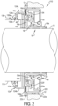
- the cassette seal arrangement 10 is configured to be mounted between a housing 12 and a shaft 14 for sealing a gap therebetween.
- the cassette seal arrangement 10 includes a sleeve 16 configured to be mounted to the shaft 14 and including a first cylindrical portion 16a that receives the shaft 14 therein and a first radially extending portion 16b extending radially outward from the cylindrical portion16a.
- a second cylindrical portion 16c extends axially from an outer end of the radially extending portion 16b and a second radially extending portion 16d extending from an end of the second cylindrical portion 16c.
- the sleeve 16 can further include an elastomeric layer 18 on an inner surface of the cylindrical portion16a and on an outboard side of the first radially extending portion 16b and the second cylindrical portion 16c of the sleeve 16.
- a retainer cartridge 20 is configured to be mounted to the housing 12 and includes a main retainer 22 and an exclusionary retainer 24 connected to one another.
- the main retainer 22 supports a seal member 26 that includes a main seal lip 28 and a pair of dust lips 30a, 30b.
- the main retainer 22 includes a cylindrical outer portion 22a that engages the housing 12 and a radially outwardly bent region 22b that extends from a first end of the cylindrical outer portion 22a and that defines a shoulder that abuts against the housing.
- the radially outwardly bent region 22b terminates in a U-shaped bend 22c that captures an outer end 24a of the exclusionary retainer 24.
- the main retainer 22 includes a first radially inwardly extending portion 22d extending inwardly from a second end of the cylindrical outer portion 22a.
- An inner cylindrical portion 22e extends axially from a radial inner end of the first radially inwardly extending portion 22d.
- a second radially inwardly extending portion 22f extends radially inward from a second end of the inner cylindrical portion 22e.
- the seal member 26 is molded on an inner end of the second radially inwardly extending portion 22f.
- the main seal lip 28 and a first of the pair of dust lips 30a engage the cylindrical portion 16a of the sleeve 16 while a second dust lip 30b of the pair of dust lips engage the first radially extending portion 16b of the sleeve 16.
- the main seal lip 28 can include a garter spring 32.
- the elastomer molded on the second radially inwardly extending portion 22f further includes a bumper region opposing the second radially extending portion 16d of the sleeve 16.
- the outer end 24a of the exclusionary retainer 24 is connected to the U-shaped bend 22c of the main retainer 22.
- the exclusionary retainer 24 further includes a cylindrical portion 24b extending axially from the outer end 24a in a direction opposite to the main retainer 22.
- a radially inwardly extending portion 24c extending radially inwardly from the cylindrical portion 24b and supporting an exclusionary seal 36.
- the exclusionary seal 36 is configured to engage the shaft and can include a pair of dust lips 36a, 36b.
- An electrically conductive non-woven element 40 is disposed longitudinally between the seal member 26 and the exclusionary seal 36.
- the electrically conductive non-woven element 40 has an outer perimeter 40a that engages the retainer cartridge 24 and an inner perimeter 40b configured to engage the shaft 14.
- the electrically conductive non-woven element 40 can be adhered to an outboard face of the first radially extending portion 16b of the sleeve 16.
- the electrically conductive non-woven element 40 can further include keyhole slots 42 extending radially inward from the outer perimeter 40a. The keyholes 42 reduce the radial load of the nonwoven element 40 and reduce the torque required to rotate the shaft 14 and sleeve 16 when in contact with the exclusion/retainer seal.
- an alternative cassette seal arrangement 110 including a modified exclusionary retainer 124 for supporting the exclusionary seal 136 in engagement with an auxiliary sleeve 114 disposed on the shaft 14.
- the modified exclusionary retainer 124 has a shorter radially inwardly extending portion 124c than the exclusionary retainer 24.
- Example embodiments are provided so that this disclosure will be thorough, and will fully convey the scope to those who are skilled in the art. Numerous specific details are set forth such as examples of specific components, devices, and methods, to provide a thorough understanding of embodiments of the present disclosure. It will be apparent to those skilled in the art that specific details need not be employed, that example embodiments may be embodied in many different forms and that neither should be construed to limit the scope of the disclosure. In some example embodiments, well-known processes, well-known device structures, and well-known technologies are not described in detail.
- first, second, third, etc. may be used herein to describe various elements, components, regions, layers and/or sections, these elements, components, regions, layers and/or sections should not be limited by these terms. These terms may be only used to distinguish one element, component, region, layer or section from another region, layer or section. Terms such as “first,” “second,” and other numerical terms when used herein do not imply a sequence or order unless clearly indicated by the context. Thus, a first element, component, region, layer or section discussed below could be termed a second element, component, region, layer or section without departing from the teachings of the example embodiments.
- spatially relative terms such as “inner,” “outer,” “beneath,” “below,” “lower,” “above,” “upper,” and the like, may be used herein for ease of description to describe one element or feature's relationship to another element(s) or feature(s) as illustrated in the figures.
- Spatially relative terms may be intended to encompass different orientations of the device in use or operation in addition to the orientation depicted in the figures. For example, if the device in the figures is turned over, elements described as “below” or “beneath” other elements or features would then be oriented “above” the other elements or features.
- the example term “below” can encompass both an orientation of above and below.
- the device may be otherwise oriented (rotated 90 degrees or at other orientations) and the spatially relative descriptors used herein interpreted accordingly.
Landscapes
- Engineering & Computer Science (AREA)
- General Engineering & Computer Science (AREA)
- Mechanical Engineering (AREA)
- Sealing Devices (AREA)
- Sealing With Elastic Sealing Lips (AREA)
Claims (2)
- Kassettendichtungsanordnung zum Abdichten zwischen einer Welle (14) und einem Gehäuse (12), umfassend:eine Hülse (16), die dazu ausgelegt ist, an der Welle (14) angebracht zu werden, und die einen zylindrischen Abschnitt (16a) und einen sich radial nach außen von dem zylindrischen Abschnitt (16a) erstreckenden Abschnitt (16b) aufweist;eine Haltepatrone (20), die einen Haupthalter (22) enthält, der dazu ausgelegt ist, an dem Gehäuse (12) angebracht zu werden und ein Dichtungselement (26) trägt, das eine Hauptdichtungslippe (28) und einen mit dem Haupthalter (22) verbundenen Ausschlusshalter (24) enthält, dadurch gekennzeichnet, dass der Ausschlusshalter (24) eine Ausschlussdichtung (36) trägt, die dazu ausgelegt ist, direkt mit der Welle (14) in Eingriff zu stehen; undein elektrisch leitfähiges Vliesstoffelement (40), das in Längsrichtung zwischen dem Dichtungselement (26) und der Ausschlussdichtung (36) angeordnet ist und mit der Haltepatrone (20) in Eingriff steht und dazu ausgelegt ist, direkt mit der Welle (14) in Eingriff zu stehen;wobei das elektrisch leitfähige Vliesstoffelement (40) an den sich radial erstreckenden Abschnitt (16b) der Hülse (16) angrenzt;das elektrisch leitfähige Vliesstoffelement (40) mit dem Ausschlusshalter (24) in Eingriff steht; unddas Dichtungselement (26) mindestens eine Staublippe (30a, 30b) enthält, die mit der Hülse (16) in Eingriff steht.
- Kassettendichtungsanordnung nach Anspruch 1, wobei die mindestens eine Staublippe (30a, 30b) eine erste Staublippe (30a), die mit dem zylindrischen Abschnitt (16a) der Hülse (16) in Eingriff steht, und eine zweite Staublippe (30b) enthält, die mit dem radial verlaufenden Abschnitt (16b) der Hülse (16) in Eingriff steht.
Applications Claiming Priority (1)
| Application Number | Priority Date | Filing Date | Title |
|---|---|---|---|
| US17/514,986 US11754188B2 (en) | 2021-10-29 | 2021-10-29 | Seal cartridge with electrically conductive non-woven grounding |
Publications (2)
| Publication Number | Publication Date |
|---|---|
| EP4174345A1 EP4174345A1 (de) | 2023-05-03 |
| EP4174345B1 true EP4174345B1 (de) | 2024-08-21 |
Family
ID=83151776
Family Applications (1)
| Application Number | Title | Priority Date | Filing Date |
|---|---|---|---|
| EP22192743.7A Active EP4174345B1 (de) | 2021-10-29 | 2022-08-30 | Dichtungspatrone mit elektrisch leitfähiger vliesstofferdung |
Country Status (3)
| Country | Link |
|---|---|
| US (1) | US11754188B2 (de) |
| EP (1) | EP4174345B1 (de) |
| CN (1) | CN116066562A (de) |
Family Cites Families (10)
| Publication number | Priority date | Publication date | Assignee | Title |
|---|---|---|---|---|
| US3114558A (en) * | 1957-07-01 | 1963-12-17 | Federal Mogul Bower Bearings | Fluid seal |
| JPS60184461U (ja) * | 1984-05-17 | 1985-12-06 | エヌオーケー株式会社 | オイルシ−ル |
| US4915892A (en) * | 1985-12-16 | 1990-04-10 | Hallite Holdings Limited | Making sealing ring assembly |
| US5292199A (en) * | 1993-05-07 | 1994-03-08 | Ford Motor Company | Axle wheel seal and bearing arrangement for a motor vehicle |
| US6692007B2 (en) * | 2001-10-31 | 2004-02-17 | Transcom, Inc. | Seal for a shaft |
| JP2007247708A (ja) | 2006-03-14 | 2007-09-27 | Nok Corp | 軸付きシール |
| DE102014010269B4 (de) | 2014-07-11 | 2020-06-18 | Carl Freudenberg Kg | Vorschaltdichtung, Vorschaltdichtungsanordnung und Dichtring, umfassend die Vorschaltdichtung |
| CN111043315A (zh) | 2019-12-20 | 2020-04-21 | 嘉科(无锡)密封技术有限公司 | 一种接地式油封 |
| CN111649073A (zh) * | 2020-06-01 | 2020-09-11 | 舍弗勒技术股份两合公司 | 密封装置和轴承组件 |
| DE102021102570A1 (de) * | 2021-02-04 | 2022-08-04 | Carl Freudenberg Kg | Erdungsring und Anordnung, die einen solchen Erdungsring umfasst |
-
2021
- 2021-10-29 US US17/514,986 patent/US11754188B2/en active Active
-
2022
- 2022-08-30 EP EP22192743.7A patent/EP4174345B1/de active Active
- 2022-09-15 CN CN202211121366.5A patent/CN116066562A/zh active Pending
Also Published As
| Publication number | Publication date |
|---|---|
| CN116066562A (zh) | 2023-05-05 |
| US11754188B2 (en) | 2023-09-12 |
| EP4174345A1 (de) | 2023-05-03 |
| US20230137020A1 (en) | 2023-05-04 |
Similar Documents
| Publication | Publication Date | Title |
|---|---|---|
| EP3835628B1 (de) | Kontaminationsausschluss für dichtungsring mit leitfähiger vliesfaser | |
| US7832735B2 (en) | Seal assembly with protective filter | |
| US5522600A (en) | Annular lubricant seal assembly with spring member | |
| US8231129B2 (en) | Sealing device | |
| EP2085667B1 (de) | Dichtungsvorrichtung und wälzlagervorrichtung | |
| EP2619487B1 (de) | Dynamische radialwellendichtungsanordnung mit kombiniertem staubausschlussdruckring | |
| WO2007132556A1 (ja) | 滑り軸受 | |
| US8028415B2 (en) | Method of installing a pinion seal to a carrier/bearing cage and an axle | |
| EP3078887A1 (de) | Dichtung | |
| US20160312895A1 (en) | Sealing assembly and protector ring | |
| US20200056652A1 (en) | Sealing arrangement for a wheel bearing | |
| WO2007095436A2 (en) | Robust sealing system for power steering input shaft | |
| MXPA05001560A (es) | Sello de tubo para bujia. | |
| EP4174345A1 (de) | Dichtungspatrone mit elektrisch leitfähiger vliesstofferdung | |
| EP3284979A2 (de) | Gebundene dichtung mit integralem sicherungsring | |
| WO2007052685A1 (ja) | 密封装置 | |
| US12410866B2 (en) | Seal cartridge with electrically conductive non-woven grounding | |
| US20240410467A1 (en) | Contaminant exclusion seal design | |
| EP3879144B1 (de) | Kunststoff-slinger mit kontaktierendem pufferelement mit labyrinth | |
| CN119103351A (zh) | 具有导电非织物接地的密封筒 | |
| EP1290365B1 (de) | Dichtung | |
| US20160069457A1 (en) | Slide ring seal | |
| CN221347844U (zh) | 一种能够实现双向轴向密封的金属密封圈及密封结构 | |
| US20260039078A1 (en) | Conductive structural body and conduction method | |
| JP3000280U (ja) | 軸受の密封装置 |
Legal Events
| Date | Code | Title | Description |
|---|---|---|---|
| PUAI | Public reference made under article 153(3) epc to a published international application that has entered the european phase |
Free format text: ORIGINAL CODE: 0009012 |
|
| STAA | Information on the status of an ep patent application or granted ep patent |
Free format text: STATUS: THE APPLICATION HAS BEEN PUBLISHED |
|
| AK | Designated contracting states |
Kind code of ref document: A1 Designated state(s): AL AT BE BG CH CY CZ DE DK EE ES FI FR GB GR HR HU IE IS IT LI LT LU LV MC MK MT NL NO PL PT RO RS SE SI SK SM TR |
|
| STAA | Information on the status of an ep patent application or granted ep patent |
Free format text: STATUS: REQUEST FOR EXAMINATION WAS MADE |
|
| 17P | Request for examination filed |
Effective date: 20231018 |
|
| RBV | Designated contracting states (corrected) |
Designated state(s): AL AT BE BG CH CY CZ DE DK EE ES FI FR GB GR HR HU IE IS IT LI LT LU LV MC MK MT NL NO PL PT RO RS SE SI SK SM TR |
|
| GRAP | Despatch of communication of intention to grant a patent |
Free format text: ORIGINAL CODE: EPIDOSNIGR1 |
|
| STAA | Information on the status of an ep patent application or granted ep patent |
Free format text: STATUS: GRANT OF PATENT IS INTENDED |
|
| RIC1 | Information provided on ipc code assigned before grant |
Ipc: F16J 15/3284 20160101ALI20240308BHEP Ipc: F16J 15/3256 20160101ALI20240308BHEP Ipc: F16J 15/3232 20160101ALI20240308BHEP Ipc: F16J 15/322 20160101ALI20240308BHEP Ipc: F16J 15/3208 20160101AFI20240308BHEP |
|
| INTG | Intention to grant announced |
Effective date: 20240403 |
|
| GRAS | Grant fee paid |
Free format text: ORIGINAL CODE: EPIDOSNIGR3 |
|
| GRAA | (expected) grant |
Free format text: ORIGINAL CODE: 0009210 |
|
| STAA | Information on the status of an ep patent application or granted ep patent |
Free format text: STATUS: THE PATENT HAS BEEN GRANTED |
|
| AK | Designated contracting states |
Kind code of ref document: B1 Designated state(s): AL AT BE BG CH CY CZ DE DK EE ES FI FR GB GR HR HU IE IS IT LI LT LU LV MC MK MT NL NO PL PT RO RS SE SI SK SM TR |
|
| REG | Reference to a national code |
Ref country code: GB Ref legal event code: FG4D |
|
| REG | Reference to a national code |
Ref country code: CH Ref legal event code: EP |
|
| REG | Reference to a national code |
Ref country code: IE Ref legal event code: FG4D |
|
| REG | Reference to a national code |
Ref country code: DE Ref legal event code: R096 Ref document number: 602022005450 Country of ref document: DE |
|
| P01 | Opt-out of the competence of the unified patent court (upc) registered |
Free format text: CASE NUMBER: APP_51948/2024 Effective date: 20240916 |
|
| REG | Reference to a national code |
Ref country code: LT Ref legal event code: MG9D |
|
| REG | Reference to a national code |
Ref country code: NL Ref legal event code: MP Effective date: 20240821 |
|
| PG25 | Lapsed in a contracting state [announced via postgrant information from national office to epo] |
Ref country code: NO Free format text: LAPSE BECAUSE OF FAILURE TO SUBMIT A TRANSLATION OF THE DESCRIPTION OR TO PAY THE FEE WITHIN THE PRESCRIBED TIME-LIMIT Effective date: 20241121 |
|
| REG | Reference to a national code |
Ref country code: AT Ref legal event code: MK05 Ref document number: 1715762 Country of ref document: AT Kind code of ref document: T Effective date: 20240821 |
|
| PG25 | Lapsed in a contracting state [announced via postgrant information from national office to epo] |
Ref country code: FI Free format text: LAPSE BECAUSE OF FAILURE TO SUBMIT A TRANSLATION OF THE DESCRIPTION OR TO PAY THE FEE WITHIN THE PRESCRIBED TIME-LIMIT Effective date: 20240821 Ref country code: NL Free format text: LAPSE BECAUSE OF FAILURE TO SUBMIT A TRANSLATION OF THE DESCRIPTION OR TO PAY THE FEE WITHIN THE PRESCRIBED TIME-LIMIT Effective date: 20240821 Ref country code: PL Free format text: LAPSE BECAUSE OF FAILURE TO SUBMIT A TRANSLATION OF THE DESCRIPTION OR TO PAY THE FEE WITHIN THE PRESCRIBED TIME-LIMIT Effective date: 20240821 Ref country code: GR Free format text: LAPSE BECAUSE OF FAILURE TO SUBMIT A TRANSLATION OF THE DESCRIPTION OR TO PAY THE FEE WITHIN THE PRESCRIBED TIME-LIMIT Effective date: 20241122 Ref country code: PT Free format text: LAPSE BECAUSE OF FAILURE TO SUBMIT A TRANSLATION OF THE DESCRIPTION OR TO PAY THE FEE WITHIN THE PRESCRIBED TIME-LIMIT Effective date: 20241223 |
|
| PG25 | Lapsed in a contracting state [announced via postgrant information from national office to epo] |
Ref country code: BG Free format text: LAPSE BECAUSE OF FAILURE TO SUBMIT A TRANSLATION OF THE DESCRIPTION OR TO PAY THE FEE WITHIN THE PRESCRIBED TIME-LIMIT Effective date: 20240821 |
|
| PG25 | Lapsed in a contracting state [announced via postgrant information from national office to epo] |
Ref country code: LV Free format text: LAPSE BECAUSE OF FAILURE TO SUBMIT A TRANSLATION OF THE DESCRIPTION OR TO PAY THE FEE WITHIN THE PRESCRIBED TIME-LIMIT Effective date: 20240821 |
|
| PG25 | Lapsed in a contracting state [announced via postgrant information from national office to epo] |
Ref country code: AT Free format text: LAPSE BECAUSE OF FAILURE TO SUBMIT A TRANSLATION OF THE DESCRIPTION OR TO PAY THE FEE WITHIN THE PRESCRIBED TIME-LIMIT Effective date: 20240821 Ref country code: IS Free format text: LAPSE BECAUSE OF FAILURE TO SUBMIT A TRANSLATION OF THE DESCRIPTION OR TO PAY THE FEE WITHIN THE PRESCRIBED TIME-LIMIT Effective date: 20241221 |
|
| PG25 | Lapsed in a contracting state [announced via postgrant information from national office to epo] |
Ref country code: HR Free format text: LAPSE BECAUSE OF FAILURE TO SUBMIT A TRANSLATION OF THE DESCRIPTION OR TO PAY THE FEE WITHIN THE PRESCRIBED TIME-LIMIT Effective date: 20240821 |
|
| PG25 | Lapsed in a contracting state [announced via postgrant information from national office to epo] |
Ref country code: RS Free format text: LAPSE BECAUSE OF FAILURE TO SUBMIT A TRANSLATION OF THE DESCRIPTION OR TO PAY THE FEE WITHIN THE PRESCRIBED TIME-LIMIT Effective date: 20241121 Ref country code: ES Free format text: LAPSE BECAUSE OF FAILURE TO SUBMIT A TRANSLATION OF THE DESCRIPTION OR TO PAY THE FEE WITHIN THE PRESCRIBED TIME-LIMIT Effective date: 20240821 |
|
| PG25 | Lapsed in a contracting state [announced via postgrant information from national office to epo] |
Ref country code: RS Free format text: LAPSE BECAUSE OF FAILURE TO SUBMIT A TRANSLATION OF THE DESCRIPTION OR TO PAY THE FEE WITHIN THE PRESCRIBED TIME-LIMIT Effective date: 20241121 Ref country code: PT Free format text: LAPSE BECAUSE OF FAILURE TO SUBMIT A TRANSLATION OF THE DESCRIPTION OR TO PAY THE FEE WITHIN THE PRESCRIBED TIME-LIMIT Effective date: 20241223 Ref country code: PL Free format text: LAPSE BECAUSE OF FAILURE TO SUBMIT A TRANSLATION OF THE DESCRIPTION OR TO PAY THE FEE WITHIN THE PRESCRIBED TIME-LIMIT Effective date: 20240821 Ref country code: NO Free format text: LAPSE BECAUSE OF FAILURE TO SUBMIT A TRANSLATION OF THE DESCRIPTION OR TO PAY THE FEE WITHIN THE PRESCRIBED TIME-LIMIT Effective date: 20241121 Ref country code: NL Free format text: LAPSE BECAUSE OF FAILURE TO SUBMIT A TRANSLATION OF THE DESCRIPTION OR TO PAY THE FEE WITHIN THE PRESCRIBED TIME-LIMIT Effective date: 20240821 Ref country code: LV Free format text: LAPSE BECAUSE OF FAILURE TO SUBMIT A TRANSLATION OF THE DESCRIPTION OR TO PAY THE FEE WITHIN THE PRESCRIBED TIME-LIMIT Effective date: 20240821 Ref country code: IS Free format text: LAPSE BECAUSE OF FAILURE TO SUBMIT A TRANSLATION OF THE DESCRIPTION OR TO PAY THE FEE WITHIN THE PRESCRIBED TIME-LIMIT Effective date: 20241221 Ref country code: HR Free format text: LAPSE BECAUSE OF FAILURE TO SUBMIT A TRANSLATION OF THE DESCRIPTION OR TO PAY THE FEE WITHIN THE PRESCRIBED TIME-LIMIT Effective date: 20240821 Ref country code: GR Free format text: LAPSE BECAUSE OF FAILURE TO SUBMIT A TRANSLATION OF THE DESCRIPTION OR TO PAY THE FEE WITHIN THE PRESCRIBED TIME-LIMIT Effective date: 20241122 Ref country code: FI Free format text: LAPSE BECAUSE OF FAILURE TO SUBMIT A TRANSLATION OF THE DESCRIPTION OR TO PAY THE FEE WITHIN THE PRESCRIBED TIME-LIMIT Effective date: 20240821 Ref country code: ES Free format text: LAPSE BECAUSE OF FAILURE TO SUBMIT A TRANSLATION OF THE DESCRIPTION OR TO PAY THE FEE WITHIN THE PRESCRIBED TIME-LIMIT Effective date: 20240821 Ref country code: BG Free format text: LAPSE BECAUSE OF FAILURE TO SUBMIT A TRANSLATION OF THE DESCRIPTION OR TO PAY THE FEE WITHIN THE PRESCRIBED TIME-LIMIT Effective date: 20240821 Ref country code: AT Free format text: LAPSE BECAUSE OF FAILURE TO SUBMIT A TRANSLATION OF THE DESCRIPTION OR TO PAY THE FEE WITHIN THE PRESCRIBED TIME-LIMIT Effective date: 20240821 |
|
| PG25 | Lapsed in a contracting state [announced via postgrant information from national office to epo] |
Ref country code: DK Free format text: LAPSE BECAUSE OF FAILURE TO SUBMIT A TRANSLATION OF THE DESCRIPTION OR TO PAY THE FEE WITHIN THE PRESCRIBED TIME-LIMIT Effective date: 20240821 Ref country code: SM Free format text: LAPSE BECAUSE OF FAILURE TO SUBMIT A TRANSLATION OF THE DESCRIPTION OR TO PAY THE FEE WITHIN THE PRESCRIBED TIME-LIMIT Effective date: 20240821 Ref country code: RO Free format text: LAPSE BECAUSE OF FAILURE TO SUBMIT A TRANSLATION OF THE DESCRIPTION OR TO PAY THE FEE WITHIN THE PRESCRIBED TIME-LIMIT Effective date: 20240821 |
|
| PG25 | Lapsed in a contracting state [announced via postgrant information from national office to epo] |
Ref country code: LU Free format text: LAPSE BECAUSE OF NON-PAYMENT OF DUE FEES Effective date: 20240830 |
|
| PG25 | Lapsed in a contracting state [announced via postgrant information from national office to epo] |
Ref country code: EE Free format text: LAPSE BECAUSE OF FAILURE TO SUBMIT A TRANSLATION OF THE DESCRIPTION OR TO PAY THE FEE WITHIN THE PRESCRIBED TIME-LIMIT Effective date: 20240821 |
|
| PG25 | Lapsed in a contracting state [announced via postgrant information from national office to epo] |
Ref country code: CZ Free format text: LAPSE BECAUSE OF FAILURE TO SUBMIT A TRANSLATION OF THE DESCRIPTION OR TO PAY THE FEE WITHIN THE PRESCRIBED TIME-LIMIT Effective date: 20240821 |
|
| PG25 | Lapsed in a contracting state [announced via postgrant information from national office to epo] |
Ref country code: IT Free format text: LAPSE BECAUSE OF FAILURE TO SUBMIT A TRANSLATION OF THE DESCRIPTION OR TO PAY THE FEE WITHIN THE PRESCRIBED TIME-LIMIT Effective date: 20240821 Ref country code: SK Free format text: LAPSE BECAUSE OF FAILURE TO SUBMIT A TRANSLATION OF THE DESCRIPTION OR TO PAY THE FEE WITHIN THE PRESCRIBED TIME-LIMIT Effective date: 20240821 |
|
| REG | Reference to a national code |
Ref country code: DE Ref legal event code: R097 Ref document number: 602022005450 Country of ref document: DE |
|
| REG | Reference to a national code |
Ref country code: BE Ref legal event code: MM Effective date: 20240831 |
|
| PLBE | No opposition filed within time limit |
Free format text: ORIGINAL CODE: 0009261 |
|
| STAA | Information on the status of an ep patent application or granted ep patent |
Free format text: STATUS: NO OPPOSITION FILED WITHIN TIME LIMIT |
|
| PG25 | Lapsed in a contracting state [announced via postgrant information from national office to epo] |
Ref country code: MC Free format text: LAPSE BECAUSE OF FAILURE TO SUBMIT A TRANSLATION OF THE DESCRIPTION OR TO PAY THE FEE WITHIN THE PRESCRIBED TIME-LIMIT Effective date: 20240821 |
|
| PG25 | Lapsed in a contracting state [announced via postgrant information from national office to epo] |
Ref country code: BE Free format text: LAPSE BECAUSE OF NON-PAYMENT OF DUE FEES Effective date: 20240831 |
|
| PG25 | Lapsed in a contracting state [announced via postgrant information from national office to epo] |
Ref country code: IE Free format text: LAPSE BECAUSE OF NON-PAYMENT OF DUE FEES Effective date: 20240830 |
|
| 26N | No opposition filed |
Effective date: 20250522 |
|
| PG25 | Lapsed in a contracting state [announced via postgrant information from national office to epo] |
Ref country code: SE Free format text: LAPSE BECAUSE OF FAILURE TO SUBMIT A TRANSLATION OF THE DESCRIPTION OR TO PAY THE FEE WITHIN THE PRESCRIBED TIME-LIMIT Effective date: 20240821 |
|
| PGFP | Annual fee paid to national office [announced via postgrant information from national office to epo] |
Ref country code: DE Payment date: 20250828 Year of fee payment: 4 |
|
| PGFP | Annual fee paid to national office [announced via postgrant information from national office to epo] |
Ref country code: FR Payment date: 20250826 Year of fee payment: 4 |
|
| PG25 | Lapsed in a contracting state [announced via postgrant information from national office to epo] |
Ref country code: CY Free format text: LAPSE BECAUSE OF FAILURE TO SUBMIT A TRANSLATION OF THE DESCRIPTION OR TO PAY THE FEE WITHIN THE PRESCRIBED TIME-LIMIT; INVALID AB INITIO Effective date: 20220830 |
|
| PG25 | Lapsed in a contracting state [announced via postgrant information from national office to epo] |
Ref country code: HU Free format text: LAPSE BECAUSE OF FAILURE TO SUBMIT A TRANSLATION OF THE DESCRIPTION OR TO PAY THE FEE WITHIN THE PRESCRIBED TIME-LIMIT; INVALID AB INITIO Effective date: 20220830 |
|
| REG | Reference to a national code |
Ref country code: CH Ref legal event code: H13 Free format text: ST27 STATUS EVENT CODE: U-0-0-H10-H13 (AS PROVIDED BY THE NATIONAL OFFICE) Effective date: 20260324 |
|
| PG25 | Lapsed in a contracting state [announced via postgrant information from national office to epo] |
Ref country code: CH Free format text: LAPSE BECAUSE OF NON-PAYMENT OF DUE FEES Effective date: 20250831 |