EP4174276B9 - Actionneur électromécanique, dispositif d'occultation comprenant un tel actionneur et procédé de commande d'un tel actionneur - Google Patents
Actionneur électromécanique, dispositif d'occultation comprenant un tel actionneur et procédé de commande d'un tel actionneur Download PDFInfo
- Publication number
- EP4174276B9 EP4174276B9 EP22204639.3A EP22204639A EP4174276B9 EP 4174276 B9 EP4174276 B9 EP 4174276B9 EP 22204639 A EP22204639 A EP 22204639A EP 4174276 B9 EP4174276 B9 EP 4174276B9
- Authority
- EP
- European Patent Office
- Prior art keywords
- electromechanical actuator
- shutter
- control unit
- housing
- electronic control
- Prior art date
- Legal status (The legal status is an assumption and is not a legal conclusion. Google has not performed a legal analysis and makes no representation as to the accuracy of the status listed.)
- Active
Links
Images




Classifications
-
- E—FIXED CONSTRUCTIONS
- E06—DOORS, WINDOWS, SHUTTERS, OR ROLLER BLINDS IN GENERAL; LADDERS
- E06B—FIXED OR MOVABLE CLOSURES FOR OPENINGS IN BUILDINGS, VEHICLES, FENCES OR LIKE ENCLOSURES IN GENERAL, e.g. DOORS, WINDOWS, BLINDS, GATES
- E06B9/00—Screening or protective devices for wall or similar openings, with or without operating or securing mechanisms; Closures of similar construction
- E06B9/24—Screens or other constructions affording protection against light, especially against sunshine; Similar screens for privacy or appearance; Slat blinds
- E06B9/26—Lamellar or like blinds, e.g. venetian blinds
- E06B9/28—Lamellar or like blinds, e.g. venetian blinds with horizontal lamellae, e.g. non-liftable
- E06B9/30—Lamellar or like blinds, e.g. venetian blinds with horizontal lamellae, e.g. non-liftable liftable
- E06B9/32—Operating, guiding, or securing devices therefor
- E06B9/322—Details of operating devices, e.g. pulleys, brakes, spring drums, drives
-
- E—FIXED CONSTRUCTIONS
- E06—DOORS, WINDOWS, SHUTTERS, OR ROLLER BLINDS IN GENERAL; LADDERS
- E06B—FIXED OR MOVABLE CLOSURES FOR OPENINGS IN BUILDINGS, VEHICLES, FENCES OR LIKE ENCLOSURES IN GENERAL, e.g. DOORS, WINDOWS, BLINDS, GATES
- E06B9/00—Screening or protective devices for wall or similar openings, with or without operating or securing mechanisms; Closures of similar construction
- E06B9/56—Operating, guiding or securing devices or arrangements for roll-type closures; Spring drums; Tape drums; Counterweighting arrangements therefor
- E06B9/68—Operating devices or mechanisms, e.g. with electric drive
-
- E—FIXED CONSTRUCTIONS
- E06—DOORS, WINDOWS, SHUTTERS, OR ROLLER BLINDS IN GENERAL; LADDERS
- E06B—FIXED OR MOVABLE CLOSURES FOR OPENINGS IN BUILDINGS, VEHICLES, FENCES OR LIKE ENCLOSURES IN GENERAL, e.g. DOORS, WINDOWS, BLINDS, GATES
- E06B9/00—Screening or protective devices for wall or similar openings, with or without operating or securing mechanisms; Closures of similar construction
- E06B9/56—Operating, guiding or securing devices or arrangements for roll-type closures; Spring drums; Tape drums; Counterweighting arrangements therefor
- E06B9/80—Safety measures against dropping or unauthorised opening; Braking or immobilising devices; Devices for limiting unrolling
- E06B9/82—Safety measures against dropping or unauthorised opening; Braking or immobilising devices; Devices for limiting unrolling automatic
- E06B9/88—Safety measures against dropping or unauthorised opening; Braking or immobilising devices; Devices for limiting unrolling automatic for limiting unrolling
-
- H—ELECTRICITY
- H02—GENERATION; CONVERSION OR DISTRIBUTION OF ELECTRIC POWER
- H02K—DYNAMO-ELECTRIC MACHINES
- H02K11/00—Structural association of dynamo-electric machines with electric components or with devices for shielding, monitoring or protection
- H02K11/30—Structural association with control circuits or drive circuits
- H02K11/33—Drive circuits, e.g. power electronics
-
- E—FIXED CONSTRUCTIONS
- E06—DOORS, WINDOWS, SHUTTERS, OR ROLLER BLINDS IN GENERAL; LADDERS
- E06B—FIXED OR MOVABLE CLOSURES FOR OPENINGS IN BUILDINGS, VEHICLES, FENCES OR LIKE ENCLOSURES IN GENERAL, e.g. DOORS, WINDOWS, BLINDS, GATES
- E06B9/00—Screening or protective devices for wall or similar openings, with or without operating or securing mechanisms; Closures of similar construction
- E06B9/56—Operating, guiding or securing devices or arrangements for roll-type closures; Spring drums; Tape drums; Counterweighting arrangements therefor
- E06B9/68—Operating devices or mechanisms, e.g. with electric drive
- E06B2009/6809—Control
-
- E—FIXED CONSTRUCTIONS
- E06—DOORS, WINDOWS, SHUTTERS, OR ROLLER BLINDS IN GENERAL; LADDERS
- E06B—FIXED OR MOVABLE CLOSURES FOR OPENINGS IN BUILDINGS, VEHICLES, FENCES OR LIKE ENCLOSURES IN GENERAL, e.g. DOORS, WINDOWS, BLINDS, GATES
- E06B9/00—Screening or protective devices for wall or similar openings, with or without operating or securing mechanisms; Closures of similar construction
- E06B9/56—Operating, guiding or securing devices or arrangements for roll-type closures; Spring drums; Tape drums; Counterweighting arrangements therefor
- E06B9/68—Operating devices or mechanisms, e.g. with electric drive
- E06B2009/6809—Control
- E06B2009/6818—Control using sensors
-
- E—FIXED CONSTRUCTIONS
- E06—DOORS, WINDOWS, SHUTTERS, OR ROLLER BLINDS IN GENERAL; LADDERS
- E06B—FIXED OR MOVABLE CLOSURES FOR OPENINGS IN BUILDINGS, VEHICLES, FENCES OR LIKE ENCLOSURES IN GENERAL, e.g. DOORS, WINDOWS, BLINDS, GATES
- E06B9/00—Screening or protective devices for wall or similar openings, with or without operating or securing mechanisms; Closures of similar construction
- E06B9/56—Operating, guiding or securing devices or arrangements for roll-type closures; Spring drums; Tape drums; Counterweighting arrangements therefor
- E06B9/68—Operating devices or mechanisms, e.g. with electric drive
- E06B2009/6809—Control
- E06B2009/6818—Control using sensors
- E06B2009/6845—Control using sensors sensing position
-
- E—FIXED CONSTRUCTIONS
- E06—DOORS, WINDOWS, SHUTTERS, OR ROLLER BLINDS IN GENERAL; LADDERS
- E06B—FIXED OR MOVABLE CLOSURES FOR OPENINGS IN BUILDINGS, VEHICLES, FENCES OR LIKE ENCLOSURES IN GENERAL, e.g. DOORS, WINDOWS, BLINDS, GATES
- E06B9/00—Screening or protective devices for wall or similar openings, with or without operating or securing mechanisms; Closures of similar construction
- E06B9/56—Operating, guiding or securing devices or arrangements for roll-type closures; Spring drums; Tape drums; Counterweighting arrangements therefor
- E06B9/68—Operating devices or mechanisms, e.g. with electric drive
- E06B2009/6809—Control
- E06B2009/6872—Control using counters to determine shutter position
-
- H—ELECTRICITY
- H02—GENERATION; CONVERSION OR DISTRIBUTION OF ELECTRIC POWER
- H02K—DYNAMO-ELECTRIC MACHINES
- H02K2207/00—Specific aspects not provided for in the other groups of this subclass relating to arrangements for handling mechanical energy
- H02K2207/03—Tubular motors, i.e. rotary motors mounted inside a tube, e.g. for blinds
Definitions
- the present invention relates to an electromechanical actuator for a blackout device.
- the present invention also relates to a screening device comprising a rail and a screen.
- the screen is driven into movement by such an electromechanical actuator disposed inside the rail.
- the present invention further relates to a method of controlling such an electromechanical actuator.
- the present invention relates to the field of occultation devices comprising a motorized drive device setting a screen in motion, between at least a first position and at least a second position.
- a motorized drive device comprises an electromechanical actuator of a movable sun protection or closing element, such as a blind, in particular a slatted blind, a shutter, a door, a grille, a curtain or any other equivalent material, hereinafter called a screen.
- a movable sun protection or closing element such as a blind, in particular a slatted blind, a shutter, a door, a grille, a curtain or any other equivalent material, hereinafter called a screen.
- a particular type of occultation device is that of Venetian blinds in which a blind is formed of slats whose height movement and, possibly, orientation, can be controlled by means of an electromechanical actuator.
- the electromechanical actuator With this type of equipment, it is known to equip the electromechanical actuator with a device for detecting the reaching of an upper end-of-travel position of the screen, this detection device being able to comprise a movable member which receives as support an upper slat of the blind, as described in the document WO-A1-2020/099628 .
- an electromechanical actuator must be able to be controlled in a normal operating mode, where it drives the screen between upper and lower end-of-travel positions and a learning operating mode which allows these upper and lower end-of-travel positions to be defined.
- An electronic control unit is generally used for this purpose and it is known to use a mechanical device to control the switching of this electronic control unit between these two operating modes. Mechanical devices of this type are known from documents EP-A2-0 844 633 , EP-A1-0 951 725 And EP-A2-2 149 668 .
- an electromechanical actuator for a concealment device a device for controlling the switching of its electronic control unit between first and second operating modes of which is of a simple, reliable and compact construction and which is stable in position.
- the document is also known US 2017/0268293 A1 which describes an electromechanical actuator of a blind device.
- the electromechanical actuator comprises an electric motor, an electronic control unit, a housing, an output shaft and a tilt control device.
- the electronic control unit is configured to control the electric motor in a first operating mode and in a second operating mode.
- the electric motor and the electronic control unit are housed inside the housing.
- the output shaft is rotatably mounted about an axis of rotation.
- the tilt control device is configured to switch the electronic control unit between the first and second operating modes.
- the tilt control device comprises a housing, a rotating element, a permanent magnet and a magnetic sensor.
- the rotating element is pivotally mounted about an axis relative to the housing, between a first position and a second position.
- the permanent magnet is mounted on the rotating element.
- the magnetic sensor is configured to detect a position of the permanent magnet.
- the shutter comprises at least one position retaining tab of the shutter, the or one of the position retaining tabs being held in position relative to the housing in each of the first and second positions of the shutter, such that each of the first and second positions of the shutter is stable.
- the tilt control device can be easily integrated into the electromechanical actuator.
- the retaining tab in the flap position relative to the housing ensures bistable operation of the tilt control device.
- the switching control device makes it possible to reliably control the switching of the electronic control unit between its at least two operating modes.
- mounting the permanent magnet on the shutter allows the tilt control device to be realized in a compact form and ensures reliable detection of its activation by an operator.
- the present invention relates, according to a third aspect, to a method for controlling an electromechanical actuator for a concealment device according to the invention and as mentioned above.
- the method implements a first step of operating the electronic control unit in the first operating mode.
- the method implements a second step of operating the electronic control unit in the second operating mode.
- This installation 100 comprises an opening, window or door, equipped with a screen 2 belonging to a screening device 1, in accordance with a first embodiment of the invention, in the example a screening device 1 of the Venetian blind type forming a slatted blind.
- the concealment device 1 may be, in particular, a pleated blind, a roller shutter, a rolling gate, a grille or a door.
- the occultation device 1 is preferably arranged outside the building.
- the occultation device 1 is arranged inside the building.
- the occulting device 1 comprises slats 3, in particular adjustable slats.
- the occulting device 1 further comprises a load bar 4.
- the screen 2 is formed of the slats 3 and the load bar 4.
- the load bar 4 makes it possible to exert tension on the screen 2.
- the load bar 4 is fixed at a lower end of the screen 2, in particular in an assembled configuration of the occultation device 1 in the installation 100.
- the screen 2 includes a final blade replacing the load bar 4, the latter being able to be weighted.
- the occulting device 1 comprises drive cords 5 configured to allow vertical movement of the blades 3 and the load bar 4.
- the drive cords 5 can also be called laces.
- the blades 3 respectively comprise openings, not shown, for the passage of each drive cord 5.
- the occultation device 1 further comprises orientation cords 6 configured to allow the orientation of the blades 3.
- the orientation cords 6 are also called ladders.
- each blade 3 of the screen 2 rests on a portion of orientation cord 6, in particular horizontal and which can be called a bar, connecting two strands of orientation cord 6, in particular vertical.
- orientation cords 6 make it possible to guarantee regular vertical spacing of the blades 3 of the screen 2.
- the orientation of the 3 blades allows, in particular, to adjust the brightness inside a room of the building.
- the concealment device 1 comprises two slides. Each of the slides is arranged along one side of the screen 2 of the concealment device 1. The slides are configured to cooperate with the blades 3 of the screen 2, so as to guide the blades 3, during the deployment and retraction of the screen 2.
- the blades 3 are guided by two cables. Each of the cables is arranged along one side of the screen 2 of the occultation device 1.
- the occulting device 1 comprises a motorized drive device 7.
- the motorized drive device 7 comprises at least one electromechanical actuator 8.
- the electromechanical actuator 8 is configured to drive, in other words, move the screen 2.
- the electromechanical actuator 8 makes it possible to lower or raise the slats 3 and the load bar 4, in other words to deploy or fold the screen 2, according to a vertical movement.
- the electromechanical actuator 8 also makes it possible to orient the slats 3.
- the occulting device 1 further comprises a rail 9, inside which is arranged the motorized drive device 7, in particular the electromechanical actuator 8, in particular in an assembled configuration of the occulting device 1.
- the rail 9 is arranged, in other words is configured to be arranged, above the screen 2, in particular in the assembled configuration of the occultation device 1.
- rail 9 is arranged above the building opening, or in the upper part of the building opening.
- the rail 9 comprises at least one bottom wall 9a and two side walls 9b.
- rail 9 has a “U” shaped section.
- the motorized drive device 7 further comprises a plurality of winders.
- the winders are configured to wind and unwind the drive cords 5, so as to cause the vertical movement of the blades 3 and the load bar 4.
- the motorized drive device 7 comprises two winders, not visible in the figure 1 .
- the number of reels is not limiting and may be different, in particular greater than two.
- the winders are arranged inside the rail 9.
- the drive cords 5 are connected, on the one hand, to the load bar 4 and, on the other hand, to the reels.
- each drive cord 5 is connected to the load bar 4 and the upper end of each drive cord 5 is connected to one of the winders.
- the motorized drive device 7 comprises tilting devices 13, generally called “tilters”. Each winder is respectively arranged inside a tilter 13. This is why the winders are not visible at the figure 1 .
- rockers 13 are arranged, in other words are configured to be arranged, inside the rail 9, in particular in the assembled configuration of the occultation device 1.
- the motorized drive device 7 comprises two rockers 13.
- the number of rockers is not limiting and may be different, in particular strictly greater than two. In the case where the number of rockers is greater than or equal to two, the electromechanical actuator may be arranged between two of the rockers.
- each rocker 13 is arranged on either side of the electromechanical actuator 8.
- each rocker 13 is arranged in the vicinity of one end of the rail 9, in the longitudinal direction thereof.
- the rockers 13 are configured to drive in rotation, over a limited range of rotation angle values, the orientation cords 6, so as to orient the blades 3.
- the motorized drive device 7, in particular the electromechanical actuator 8 is controlled by a control unit.
- the control unit is configured to control, i.e. command, the motorized drive device 7, in particular the electromechanical actuator 8.
- the control unit may be, for example, a local control unit 14 or a central control unit 15.
- the local control unit 14 can be connected, by wired or wireless connection, to the central control unit 15.
- the central control unit 15 can control the local control unit 14, as well as other similar local control units distributed throughout the building.
- the motorized drive device 7 is preferably configured to execute the movement commands, in particular for raising or lowering and, possibly, for orienting the screen 2 of the occultation device 1, which can be issued, in particular, by the local control unit 14 or the central control unit 15.
- the installation 100 and, more particularly, the concealment device 1 comprises either the local control unit 14, or the central control unit 15, or the local control unit 14 and the central control unit 15.
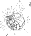
- Means for controlling the electromechanical actuator 8, allowing the movement of the screen 2 of the occultation device 1 as well as the orientation of the blades 3 of the screen 2, comprise at least one electronic control unit 19 illustrated in figures 3 And 4
- the electronic control unit 19 is capable of operating an electric motor 18 of the electromechanical actuator 8 and, in particular, of enabling the electric motor 18 to be supplied with electrical energy.
- the electric motor 18 may be of the brushless type with electronic commutation, also called “BLDC” (acronym for the English term BrushLess Direct Current) or “synchronous with permanent magnets”, of the asynchronous type or of the direct current type.
- BLDC brushless type with electronic commutation
- synchronous with permanent magnets of the asynchronous type or of the direct current type.
- the electronic control unit 19 is integrated into the electromechanical actuator 8.
- the electronic control unit 19 controls, in particular, the electric motor 18, so as to open or close the screen 2, as well as so as to orient the blades 3 of the screen 2, as described above.
- the electronic control unit 19 comprises a printed circuit board 42, visible in figures 4 And 5 and which supports various electronic components necessary for controlling the electric motor 18, including those mentioned below.
- the electronic control unit 19 may comprise several printed circuit boards.
- the electronic control unit 19 comprises at least one communication module 49, in particular for receiving control orders, the control orders being emitted by an order transmitter, such as the local control unit 14 or central control unit 15, these orders being intended to control the motorized drive device 7.
- the communication module 49 of the electronic control unit 19 is of the wired type, in other words it allows the reception and, possibly, the transmission of control orders transmitted by wired means.
- the electronic control unit 19, the local control unit 14 and/or the central control unit 15 can be in communication with a weather station, not shown, arranged inside the building or remote to the outside of the building, including, in particular, one or more sensors that can be configured to determine, for example, a temperature, a brightness or even a wind speed, in the case where the weather station is remote to the outside of the building.
- the electronic control unit 19, the local control unit 14 and/or the central control unit 15 may also be in communication with a server 27, so as to control the electromechanical actuator 8 according to data made available remotely via a communication network, in particular an internet network which can be connected to the server 27.
- the electronic control unit 19 can be controlled from the local control unit 14 or central control unit 15.
- the local control unit 14 or central control unit 15 is provided with a control keyboard.
- the control keyboard of the local control unit 14 or central control unit 15 comprises one or more selection elements 50 and, optionally, one or more display elements 51.
- the selection elements may be push buttons or sensitive keys
- the display elements may be light-emitting diodes, an LCD (acronym for the English term “Liquid Crystal Display”) or TFT (acronym for the English term “Thin Film Transistor”) display.
- the selection and display elements may also be produced by means of a touch screen.
- the local control unit 14 or central control unit 15 comprises at least one communication module 48.
- the communication module 48 of the local control unit 14 or central control unit 15 is configured to transmit, in other words emit, control orders, in particular by wired means.
- the communication module 48 of the local control unit 14 or central control unit 15 can also be configured to receive, in other words receive, control orders, in particular via the same means.
- the communication module 48 of the local control unit 14 or central control unit 15 is hereinafter referred to as the first communication module. Furthermore, the communication module communication 49 of the electronic control unit 19 is hereinafter called the second communication module.
- the first communication module 48 of the local control unit 14 or central control unit 15 is configured to communicate, in other words communicates, with the second communication module 49 of the electronic control unit 19.
- the first communication module 48 of the local control unit 14 or central control unit 15 exchanges control orders with the second communication module 49 of the electronic control unit 19, either in a one-way or two-way manner.
- the local control unit 14 is a control point, which may be fixed or mobile.
- a fixed control point may be a control box intended to be fixed on a facade of a wall of the building or on a face of the fixed frame of a window or a door.
- a mobile control point may be a remote control, a smartphone or a tablet.
- the local control unit 14 or central control unit 15 further comprises a controller 52.
- the control means of the electromechanical actuator 8 comprise hardware and/or software means.
- the hardware means may comprise at least one microcontroller 29, as illustrated in figure 4 .
- the motorized drive device 7, in particular the electronic control unit 19, is preferably configured to execute movement control orders, in particular for deploying or retracting the screen 2 of the occultation device 1, as well as for orienting the slats 3. These control orders can be issued, in particular, by the local control unit 14 or by the central control unit 15.
- the motorized drive device 7 can be controlled by the user, for example by receiving a control command corresponding to pressing the or one of the selection elements 50 of the local 14 or central 15 control unit.
- the motorized drive device 7 can also be controlled automatically, for example by receiving a control command corresponding to at least one signal from at least one sensor, not shown, and/or a signal from a clock, not shown.
- the sensor and/or the clock can be integrated into the local control unit 14 or the central control unit 15.
- the sensor and/or clock may also be considered as corresponding to a control unit, in particular a local control unit 14.
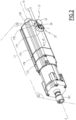
- the electromechanical actuator 8 comprises, among other things, the electric motor 18 and the electronic control unit 19.
- the electric motor 18 comprises a stator 182, a rotor 184 and a rotation shaft 186.
- the rotation shaft 186 is integral with the rotor 184.
- the rotation shaft 186 is configured to be driven in rotation, in other words is driven in rotation, about an axis of rotation X.
- the rotation shaft 186 protrudes at the two opposite ends of the electromechanical actuator 8 and constitutes an output shaft for this electromechanical actuator 8.
- the rotation shaft 186 is axially limited to the length of the electric motor 18 and connected to two output shafts of the electromechanical actuator 8 which respectively protrude at each of the ends thereof, or even to an output shaft which only protrudes at one end thereof.
- stator 182 and the rotor 184 are positioned coaxially around the axis of rotation X. Furthermore, the rotation shaft 186 is integrated or coupled to the rotor 184.
- the axis of rotation X is also the axis of rotation of the winders, in a mounted configuration of the motorized drive device 7.
- the electromechanical actuator 8 makes it possible to move the screen 2 of the occultation device 1, in particular in a vertical movement, as well as to orient the slats of the screen 2.
- the electromechanical actuator 8 further comprises an electrical power supply cable 10.
- the electromechanical actuator 8 is configured to be powered, in other words is powered, with electrical energy by a main electrical power source 54, via the electrical power supply cable 10.
- the main electrical power source 54 may be a mains electrical power supply network or a battery, which may be recharged, for example, by a photovoltaic panel or a charger, not shown.
- the electromechanical actuator 8 further comprises a casing 17, in particular tubular.
- the electric motor 18 and the electronic control unit 19 are housed, in other words mounted, inside the casing 17, in particular in an assembled configuration of the electromechanical actuator 8.
- the casing 17 of the electromechanical actuator 8 comprises a plurality of sections, including at least three sections designated by the references 17A, 17B, 17C. It is parallelepiped shape and, more particularly, has a generally rectangular section.
- the casing 17 of the electromechanical actuator 8 is cylindrical in shape with a circular section.
- the electromechanical actuator 8 further comprises at least one reducer 12.
- the reducer 12 comprises at least one reduction stage.
- the reduction stage may be an epicyclic type gear train.
- the type and number of reduction stages of the reducer are not limiting.
- the reduction stages may be, for example, two or three in number.
- Each end of the rotation shaft 186 carries a sleeve 187 for coupling to a drive shaft 11 of one of the winders.
- Each reel is thus driven in rotation, at the level of one of the rockers 13, by one of the drive shafts 11 coupled with the output shaft 186 of the electromechanical actuator 8.
- the electromechanical actuator 8 further comprises a brake 46, as illustrated in figure 3 .
- the brake 46 may be a spring brake, a cam brake, a magnetic brake or an electromagnetic brake.
- the reducer 12 and the brake 46 are also housed in the casing 17 of the electromechanical actuator 8.
- the reducer 12 and the brake 46 are arranged outside the casing 17 of the electromechanical actuator 8.
- the electromechanical actuator 8 further comprises an end-of-travel detection device 21.
- the screen 2 comprises the plurality of blades 3, including a first blade 3h.
- the first blade 3h faces the bottom wall 9a of the rail 9, in particular in the assembled configuration of the occultation device 1.
- the first blade 3h of the screen 2 corresponds to the upper blade 3 of the screen 2.
- a high position in particular a safety position, corresponds to the first slat 3h of the screen 2 resting against an element of the end-of-travel detection device 21.
- the end-of-travel detection device 21 makes it possible, in particular, to determine whether the upper end-of-travel position of the screen 2 has been reached.
- the end-of-travel detection device 21 is generally called a “mushroom”.
- An upper end position in particular an operating end position, corresponds to a predetermined upper end position, in particular programmed by means of the electronic control unit 19 and determined by means of a counting device 35.
- a lower end-of-travel position corresponds to a predetermined lower end-of-travel position, in particular programmed by means of the electronic control unit 19 and determined by means of the counting device 35, or to the support of the load bar 4 against a threshold of the opening of the building, or even to the complete deployment of the screen 2.
- the counting device 35 may be of the magnetic type.
- Such a counting device 35 comprises at least one wheel, which can be assembled on the rotation shaft 186 of the electric motor 18, and Hall effect sensors, which are not shown in detail.
- the type of counting device 35 is not limiting and may be different, in particular of the optical type or of the time type and produced through the microcontroller 29 of the electronic control unit 19.
- the end-of-travel detection device 21 comprises a member 22, movable inside a housing 17D formed by a part of the casing 17, in the example in one piece with the part 17A of the casing 17, and, optionally, an elastic return member 23 formed by a helical spring.
- the housing 17D of the end-of-travel detection device 21 may be formed by a part of the casing 17 attached to the part 17A of the casing 17 and fixed thereto, for example by means of fixing elements by screwing or by elastic snap-fastening.
- the housing 17D of the end-of-travel detection device 21 is cylindrical and has an internal section of generally circular shape.
- the housing 17D of the end-of-travel detection device 21 is parallelepipedal in shape.
- the elastic return member 23 may be other than a helical spring, for example a block of elastically deformable material.
- the member 22 is movable in translation along an axis A22 radial to the axis of rotation X.
- the member 22 is provided with a rectilinear rod 22A which is engaged in a hollow tube 17E, formed by a part of the casing 17 and which is centered on the axis A22.
- the translational movement of the member 22 along the axis A22 is guided by the cooperation of shapes of the parts 17E and 22A.
- the member 22 comprises a head 22B projecting from the housing 17D and intended to receive the first blade 3h in support, when the screen 2 reaches its upper end-of-travel position. To do this, the housing 17D and the member 22 are engaged from above in a slot, not shown, formed in the bottom wall 9a of the rail 9. When it is pushed back by the first blade 3h along the axis A22, the member 22 actuates a switch 43 carried by the printed circuit board 42. This allows the electronic control unit 19 to detect that the screen 2 is in the upper end-of-travel position.
- the casing 17 is made at least partly from a metallic material.
- the material of the housing of the electromechanical actuator is not limiting and may be different. It may, in particular, be a plastic material.
- the electronic control unit 19 is configured to control, in other words command, the electric motor 18 in a first operating mode, called control, normal or usage, where it supplies electrical energy to the electric motor 18 as a function of the upward or downward movements of the screen 2, as well as the orientation movements of the blades 3 of the screen 2.
- the electronic control unit 19 is also configured to control, in other words command, the electric motor 18 in a second operating mode, in particular learning, configuration, programming or adjustment, which implements the counting device 35 to determine and memorize one or more end-of-travel positions of the screen 2.
- the electromechanical actuator 8 further comprises a tilt control device 25.
- the tilt control device 25 is configured to switch, in other words toggles, the electronic control unit 19 between the first and second operating modes.
- the tilt control device 25 is based on magnetic detection technology, more reliable than purely mechanical tilt control devices of the prior art, which makes it possible to know precisely when the electronic control unit 19 must switch between the first and second operating modes.
- the tilt control device 25 is adjacent to the end-of-travel detection device 21.
- the tilt control device 25 can be inserted into the same slot provided in the bottom wall 9a of the rail 9 as that of the end-of-travel detection device 21 or into an adjacent slot provided in the bottom wall 9a of the rail 9 to that of the end-of-travel detection device 21, while being accessible from below this rail 9.
- the tilting control device 25 is positioned in a manner comparable to the purely mechanical devices of the prior art, so that its incorporation into the occulting device 1 according to the invention does not fundamentally change the working habits of an operator accustomed to equipment already present on the market and comprising a purely mechanical tilting control device.
- the tilt control device 25 comprises a flap 26, visible in perspective from two different angles at the figure 6 .
- the shutter 26 is pivotally mounted, around an axis A25, in a housing 17F, formed by a part of the casing 17, in the example in one piece with the part 17A of the casing 17.
- the housing 17F of the tilting control device 25 may be formed by a part of the casing 17 attached to the part 17A of the casing 17 and fixed thereto, for example by means of fixing elements by screwing or by elastic snap-fastening.
- the 17F case can also be called the first case and the 17D case can also be called the second case.
- the axis A25 of articulation of the flap 26 relative to the housing 17F is parallel to the axis of rotation X, in particular in the assembled configuration of the electromechanical actuator 8.
- the axis A25 can be oriented differently, in particular be perpendicular to the axis of rotation X.
- the shutter 26 is made of a non-magnetic material.
- the shutter 26 comprises a first panel 262 and a second panel 264.
- first and second panels 262, 264 each extend along a plane P262, P264.
- the planes P262, P264 define between them an angle ⁇ 26 around an axis A26 of the shutter 26 which coincides with the axis A25 in the mounted configuration of the shutter 26 in the housing 17F.
- B17 an edge, called “free”, of the housing 17F, opposite the part 17A of the casing 17. This edge B17 delimits an access opening to the internal volume of the housing 17F, in which houses shutter 26.
- this edge B17 has a generally rectangular shape, with rounded corners, which corresponds to the section of the housing 17F in its part furthest from the part 17A of the casing 17.
- the axis A25 is parallel to the short sides of the edge B17 and is arranged at an equal distance from these short sides.
- inserts A) and B) represent two stable operating positions of the tilt control device 25.
- an external surface S264 of the second panel 264 of the shutter 26 is flush with the edge B17 in a first position, called extreme, of the shutter 26 shown in Figures 2 to 4 and on insert A) of the figure 5 .
- an external surface S262 of the first panel 262 of the flap 26 is flush with this same edge B17 in a second position, called extreme, of the flap 26 shown on the insert B) of the figure 5 .
- the shutter 26 can take all intermediate positions between the first position and the second position, by rotating around the axis A25.
- the sum of the angles ⁇ 26 and ⁇ 26 is equal to 180°.
- the first panel 262 is provided, on its external surface S262, with a first hollow housing 263.
- this first hollow housing 263 makes it possible to receive the tip of a tool, such as a screwdriver, when an operator exerts a pivoting force on the first panel 262 around the axes A25, A26, as represented by the arrow F1 on the insert B) of the figure 5 , so as to switch the shutter 26 from its second position to its first position.
- a tool such as a screwdriver
- the second panel 264 is provided, on its external surface S264, with a second hollow housing 265.
- this second hollow housing 265 makes it possible to receive the end of a tool, such as a screwdriver, when an operator exerts a pivoting force on the second panel 264 around the axes A25, A26, as represented by the arrow F2 on the insert A) of the figure 5 , so as to switch the shutter 26 from its first position to its second position.
- a tool such as a screwdriver
- first and second panels 262, 264 are devoid of first and second hollow housings 263, 265.
- the shutter 26, in particular the second panel 264 comprises a housing 266, in which is arranged a permanent magnet 27, which belongs to the tilting control device 25.
- the permanent magnet 27 is completely received in the housing 266.
- a portion of the permanent magnet 27 may project from the housing 266.
- the tilt control device 25 comprises a magnetic sensor 28, in particular a Hall effect sensor.
- This magnetic sensor 28 is mounted inside the casing 17, close to the housing 17F, more precisely close to an inner surface of this housing 17F.
- This magnetic sensor 28 is supported by the printed circuit board 42, or by another support, which also belongs to the electronic control unit 19.
- the magnetic sensor 28 is able to signal to the microcontroller 29 that the tilt control device 25 has been actuated, due to the application of one of the forces represented by the arrows F1, F2.
- the internal shape of the housing 17F is compatible with the pivoting of the shutter 26, in particular of the second panel 264, between its first and second positions shown on the two inserts A, B of the figure 5 .
- the inner surface of the housing 17F comprises a section 172 in the shape of a cylinder with a circular section centered on the axis A25 and whose radius is greater than or equal to the largest dimension of the second panel 264 measured radially to the axis A26.
- the flap 26 comprises at least one retaining tab at position 268 of the flap 26.
- the flap 26, in particular the first panel 262, comprises a single retaining tab in position 268.
- the housing 17F comprises a first stop and a second stop.
- the first stop is configured to cooperate, in other words cooperates, with the retaining tab in position 268, when the flap 26 is in the first position.
- the second stop is configured to cooperate, in other words cooperates, with the retaining tab in position 268, when the flap 26 is in the second position.
- the housing 17F in particular its inner surface, comprises, on the one hand, a notch 174 defining the first stop of the housing 17F and, on the other hand, a re-entrant corner 176 and a recess 178 defining the second stop of the housing 17F.
- the retaining tab in position 268 is configured to cooperate, in other words cooperates, with the notch 174 in the first position of the flap 26 and with the re-entrant corner 176 and the recess 178 in the second position of this flap 26.
- the retaining tab at position 268 is elastically deformable.
- the retaining tab at position 268 comprises a free end 268A.
- the position shown on insert A of the figure 5 is a stable position.
- the permanent magnet 27 is not likely to be accidentally moved around the axis A25. No parasitic movement of the permanent magnet 27 around the axis A25 is therefore likely to be detected by the magnetic sensor 28.
- the retaining tab at position 268 further comprises a bead 268B.
- the free end 268A of the retaining tab in position 268 is engaged in the re-entrant corner 176 and the bead 268B of the retaining tab in position 268 is engaged in the recess 178.
- the bead 268B can come out of the recess 178.
- the position shown on insert B) of the figure 5 is also a stable position.
- the permanent magnet 27 is not likely to be accidentally moved around the axis A25. No parasitic movement of the permanent magnet 27 around the axis A25 is therefore likely to be detected by the magnetic sensor 28.
- the shutter 26 can be called “bistable", because the two positions shown on the inserts A) and B) of the figure 5 are stable positions, in which the shutter 26 is immobilized in rotation around the axis A25 by support of the retaining tab in position 268 on the internal surface of the housing 17F, more particularly at the level of the concave internal reliefs 174, 176, 178.
- the flap 26 comprises a plurality of retaining tabs in position 268.
- the flap 26 may be equipped with a first retaining tab in position 268, configured to bear, in other words resting, on the housing 17F, when the latter is in its first position and with a second retaining tab in position 268, configured to bear, in other words resting, on the housing 17F, when it is in its second position, the second retaining tab in position 268 being different from the first retaining tab in position 268.
- the first retaining tab in position 268 is configured to cooperate, in other words cooperate, with the notch 174.
- the second retaining tab in position 268 is configured to cooperate, in other words cooperate, with the recess 178.
- the position of the permanent magnet 27 can be located by the magnetic sensor 28, for example by detecting the distance and/or the relative orientation(s) of the South pole or the North pole of the permanent magnet 27 relative to the magnetic sensor 28.
- This position of the permanent magnet 27 detected by the magnetic sensor 28 can be stored in a memory 47, in particular non-volatile, of the electronic control unit 19, in particular of the microcontroller 29, in the form of a parameter representative of this position.
- This parameter can be binary, for example equal to 0 or 1, to represent either the position of the insert A) or the position of the insert B) of the figure 5 .
- this parameter may be proportional and correspond to a distance or angle value measured between the magnetic sensor 28 and the South or North pole of the permanent magnet 27.
- the electromechanical actuator 8 further comprises a mechanical member 126.
- the mechanical member 26 is configured to deliver, in other words delivers, sound information, when the shutter 26 pivots between its first position and its second position, and/or vice versa.
- the mechanical member 126 is an elastic return element, in particular a spring.
- the mechanical member 126 is interposed between the flap 26, which is comparable to the flap 26 of the first embodiment, and a part 17F1, in particular the bottom, of the housing 17F.
- the flap 26 and the housing 17F belong to the tilt control device 25.
- the mechanical member 126 is housed, in other words is configured to be housed, inside the housing 17F, in particular in the assembled configuration of the electromechanical actuator 8.
- the shutter 26 further comprises two holding tabs 269. Furthermore, the mechanical member 126 is mounted, in other words is configured to be mounted, on the two holding tabs 269 of the shutter 26, in particular in the assembled configuration of the electromechanical actuator 8.
- the mechanical member 126 comes to bear, in other words is configured to come to bear, against the part 17F1 of the housing 17F, when the flap 26 pivots between its first position and its second position, and/or vice versa.
- the mechanical member 126 is compressed and then suddenly relaxes, making a “click” noise which is perceived by the user.
- the user is informed by the sound information delivered by the mechanical member 126 that the shutter 26 has actually changed position, from its first position to its second position, or vice versa.
- the mechanical member 126 can deliver such information when the shutter 26 pivots from its first position to its second position, from its second position to its first position or in both cases.
- the mechanical member 126 is metallic, for example made of steel.
- the mechanical member 126 can be made of another material, in particular composite.
- the mechanical member 126 is loop-shaped.
- the mechanical member 126 comprises a rectilinear portion 126A intended to be mounted on the two retaining tabs 269 of the flap 26, in the manner of a hinge.
- the mechanical member 126 comprises two curved ends 126B, 126C, between which is defined a support portion of the mechanical member 126 against the portion 17F1 of the housing 17F.
- the mechanical member 126 may have a different shape or be replaced by another mechanical member, such as, for example, a clip or a tab, capable of delivering sound information to the user when the flap 26 pivots between its first and second positions, or vice versa.
- This method is implemented by means of the electronic control unit 19 and, in particular, the microcontroller 29.
- the method initially comprises a first step 1001 of powering up the electromechanical actuator 8.
- a first value V1 of the parameter representing the position of the permanent magnet 27 detected by the magnetic sensor 28 has been stored in the memory 47 of the electronic control unit 19.
- This first value V1 is stored in the memory 47, including when the electrical power supply to the electromechanical actuator 8 is stopped.
- the method comprises a second step 1002 of reading the first value V1, in the memory 47 of the electronic control unit 19.
- the second reading step 1002 can be implemented following the first step 1001 of powering up the electromechanical actuator 8.
- the memorization of the first value V1 is implemented during a step of powering up the electromechanical actuator 8 prior to the present powering up step 1001.
- the method comprises a third step 1003 of detecting the position of the permanent magnet 27 by the magnetic sensor 28.
- a second value V2 of the same parameter than that of the first value V1 is determined during this third detection step 1003. Then, this second value V2 is stored in the memory 47 of the electronic control unit 19.
- the third detection step 1003 can be implemented following the first step 1001 of powering up the electromechanical actuator 8.
- the order of the second and third steps 1002, 1003 may be reversed or they may be performed simultaneously.
- the method comprises a fourth step 1004 of comparing the first value V1, read during the second reading step 1002, with the second value V2, determined during the third detection step 1003.
- the method comprises a first step 1005 of operating the electronic control unit 19 in the first operating mode and a second step 1006 of operating the electronic control unit 19 in the second operating mode.
- the method implements the first step 1005 of operating the electronic control unit 19 in the first operating mode.
- the tilt control device 25 has not been actuated.
- the first step 1005 of putting into operation, in other words of control, of the electromechanical actuator 8 is executed.
- the method implements the second step 1006 of operating the electronic control unit 19 in the second operating mode.
- the tilt control device 25 has been actuated, passing from one of the positions shown to the figure 5 to the other of these positions.
- the second step 1006 of putting into operation, in other words of adjustment, of the actuator electromechanical 8 is performed.
- the electromechanical actuator 8 can be controlled in the second operating mode by the electronic control unit 19, in particular in an operating mode making it possible to adjust at least one of the end-of-travel positions.
- the tilt control device can be easily integrated into the electromechanical actuator.
- the retaining tab in the position of the shutter relative to the housing ensures bistable operation of the tilt control device.
- the switching control device makes it possible to reliably control the switching of the electronic control unit between at least its two operating modes.
- mounting the permanent magnet on the shutter allows the tilt control device to be realized in a compact form and ensures reliable detection of its activation by an operator.
- the motorized drive device 7 comprises, in addition to a plurality of first winders of the drive cords 5, a plurality of second winders of the orientation cords 6.
- the drive cords 5 are connected, on the one hand, to the load bar 4 and, on the other hand, to the first winders.
- the orientation cords 6 are connected, on the one hand, to the load bar 4 and to the blades 3 and, on the other hand, to the second winders.
- the lower end of each drive cord 5 is connected to the load bar 4 and the upper end of each drive cord 5 is connected to one of the first winders, in particular in the assembled configuration of the occultation device 1 in the installation 100.
- each orientation cord 6 is connected to the load bar 4 and the upper end of each orientation cord 6 is connected to one of the second winders, in particular in the assembled configuration of the occultation device 1 in the installation 100.
- the first and second winders are arranged inside the rail 9.
- the motorized drive device 7 comprises two chains for driving and orienting the blades 3 of the screen 2, replacing the drive cords 5 and the orientation cords 6.
- each chain is arranged inside one of the slides, arranged along one side of the screen 2 of the occultation device 1.
- the second communication module 49 of the electronic unit of control 19 is configured to receive, i.e. receives, and, optionally, to transmit, i.e. transmits, control orders transmitted by wireless means, in particular, radioelectric control orders.
- the first communication module 48 of the local control unit 14 or central control unit 15 is configured to transmit, i.e. transmits, and, optionally, to receive, i.e. receives, control orders, in particular by wireless means, for example radioelectric.
- the magnetic sensor 28 may be different from a Hall effect sensor. It may be an inductive sensor or a magnetoresistive sensor, which may be based, for example, on a so-called “GMR” technology (acronym for “Giant Magneto Resistance”).
- a clearance is visible between the free end 268A of the retaining tab in position 268 and the edge of the notch 174 or the edge of the re-entrant corner 176 and between the bead 268B of the retaining tab in position 268 and the edge of the recess 178.
- at least one of the parts 268A, 268B of the retaining tab in position 268 may be in contact with the edge of one of these concave internal reliefs 174, 176, 178 in the first and/or in the second position of the flap 26.
- the tilt control device 25 may be configured to switch the electronic control unit 19 into another operating mode.
- This other operating mode of the electronic control unit 19 may be in addition to or in replacement of the second operating mode, called “configuration” of one or more end-of-travel positions of the screen 2.
- the predetermined sequence of switching of the shutter 26 to enter one of the operating modes can be defined as a function of the number of successive switchings and/or a duration of each switching of the shutter 26.
Landscapes
- Engineering & Computer Science (AREA)
- Structural Engineering (AREA)
- Architecture (AREA)
- Civil Engineering (AREA)
- Microelectronics & Electronic Packaging (AREA)
- Power Engineering (AREA)
- Reciprocating, Oscillating Or Vibrating Motors (AREA)
- Operating, Guiding And Securing Of Roll- Type Closing Members (AREA)
- Control Of Electric Motors In General (AREA)
- Portable Nailing Machines And Staplers (AREA)
Applications Claiming Priority (1)
| Application Number | Priority Date | Filing Date | Title |
|---|---|---|---|
| FR2111630A FR3128732B1 (fr) | 2021-11-02 | 2021-11-02 | Actionneur électromécanique, dispositif d’occultation comprenant un tel actionneur et procédé de commande d’un tel actionneur |
Publications (3)
| Publication Number | Publication Date |
|---|---|
| EP4174276A1 EP4174276A1 (fr) | 2023-05-03 |
| EP4174276B1 EP4174276B1 (fr) | 2024-09-04 |
| EP4174276B9 true EP4174276B9 (fr) | 2024-11-13 |
Family
ID=79601949
Family Applications (1)
| Application Number | Title | Priority Date | Filing Date |
|---|---|---|---|
| EP22204639.3A Active EP4174276B9 (fr) | 2021-11-02 | 2022-10-31 | Actionneur électromécanique, dispositif d'occultation comprenant un tel actionneur et procédé de commande d'un tel actionneur |
Country Status (3)
| Country | Link |
|---|---|
| EP (1) | EP4174276B9 (pl) |
| FR (1) | FR3128732B1 (pl) |
| PL (1) | PL4174276T3 (pl) |
Families Citing this family (1)
| Publication number | Priority date | Publication date | Assignee | Title |
|---|---|---|---|---|
| EP4583378A1 (en) * | 2024-01-08 | 2025-07-09 | Johnson Electric International AG | Roller shutter equipment, motor and brake device |
Family Cites Families (7)
| Publication number | Priority date | Publication date | Assignee | Title |
|---|---|---|---|---|
| DE19648825A1 (de) | 1996-11-26 | 1998-05-28 | Alsthom Cge Alcatel | Endlagenschaltvorrichtung einer elektromotorisch angetriebenen Jalousie |
| DE19750210C2 (de) | 1997-11-13 | 2000-03-16 | Gross Hans | Endschaltervorrichtung |
| EP2149668B1 (de) | 2008-07-30 | 2016-03-23 | Gerhard Geiger GmbH & Co. | Endlageneinstellvorrichtung |
| FR2935424B1 (fr) * | 2008-09-01 | 2012-12-28 | Window Automation Industry Srl | Actionneur pour ecran domotique, procede et outil de configuration d'un tel actionneur. |
| NL2016447B1 (nl) * | 2016-03-17 | 2017-10-05 | Coulisse Bv | Inrichting voor het handmatig bedienen van een gemotoriseerde aandrijving van een scherm, zoals een raambekleding en werkwijze voor het opslaan van instelwaarden behorende bij verschillende posities van het scherm |
| FR3057293B1 (fr) * | 2016-10-10 | 2018-11-30 | Somfy Sas | Actionneur electromecanique et store a lames comprenant un tel actionneur |
| FR3088670B1 (fr) | 2018-11-16 | 2022-06-03 | Somfy Activites Sa | Actionneur electromecanique et dispositif d'occultation comprenant un tel actionneur |
-
2021
- 2021-11-02 FR FR2111630A patent/FR3128732B1/fr active Active
-
2022
- 2022-10-31 EP EP22204639.3A patent/EP4174276B9/fr active Active
- 2022-10-31 PL PL22204639.3T patent/PL4174276T3/pl unknown
Also Published As
| Publication number | Publication date |
|---|---|
| FR3128732A1 (fr) | 2023-05-05 |
| PL4174276T3 (pl) | 2025-01-13 |
| EP4174276B1 (fr) | 2024-09-04 |
| EP4174276A1 (fr) | 2023-05-03 |
| FR3128732B1 (fr) | 2023-11-10 |
Similar Documents
| Publication | Publication Date | Title |
|---|---|---|
| EP3880930B1 (fr) | Actionneur électromécanique et dispositif d'occultation comprenant un tel actionneur | |
| EP4172452B1 (fr) | Dispositif d'occultation comprenant un dispositif d'entraînement motorisé | |
| EP4136309A1 (fr) | Dispositif d'occultation | |
| WO2022090174A1 (fr) | Procédé de commande en fonctionnement d'un dispositif d'occultation et dispositif d'occultation associé | |
| EP4174276B1 (fr) | Actionneur électromécanique, dispositif d'occultation comprenant un tel actionneur et procédé de commande d'un tel actionneur | |
| EP4713554A1 (fr) | Actionneur electromecanique pour un dispositif d'occultation et dispositif d'occultation comprenant un tel actionneur electromecanique | |
| EP3969715A1 (fr) | Actionneur électromécanique et installation de fermeture, d'occultation ou de protection solaire comprenant un tel actionneur électromécanique | |
| EP4008876B1 (fr) | Actionneur électromécanique et installation de fermeture, d'occultation ou de protection solaire comprenant un tel actionneur électromécanique | |
| EP3216963B1 (fr) | Fenêtre oscillo-battante pour un bâtiment et installation domotique comprenant une telle fenêtre oscillo-battante | |
| EP4355975B1 (fr) | Dispositif d'occultation | |
| EP3190253B1 (fr) | Fenêtre oscillo-battante pour un bâtiment et installation domotique comprenant une telle fenêtre oscillo-battante | |
| EP4162139B1 (fr) | Actionneur électromécanique d'un dispositif d'occultation et dispositif d'occultation comprenant un tel actionneur électromécanique | |
| WO2022148734A1 (fr) | Dispositif d'entraînement motorisé pour un dispositif d'occultation, dispositif d'occultation et procédé de commande en fonctionnement associés | |
| EP4345243B1 (fr) | Dispositif d'occultation | |
| EP4244457B1 (fr) | Procédé de commande en fonctionnement d'un dispositif d'occultation et dispositif d'occultation associé | |
| EP4290745B1 (fr) | Actionneur électromécanique et dispositif d'occultation comprenant un tel actionneur | |
| EP4202173B1 (fr) | Actionneur électromécanique, dispositif d'occultation comprenant un tel actionneur et procédé d'assemblage d'un tel actionneur | |
| EP4704501A1 (fr) | Dispositif d'alimentation en énergie électrique, dispositif d'entraînement motorisé comprenant un tel dispositif d'alimentation en énergie électrique, et dispositif d'occultation associé | |
| EP4576463A1 (fr) | Dispositif d'alimentation en énergie électrique, dispositif d'entraînement motorisé comprenant un tel dispositif d'alimentation en énergie électrique, et dispositif d'occultation associé | |
| WO2022207133A1 (fr) | Actionneur électromécanique et installation de fermeture, d'occultation ou de protection solaire comprenant un tel actionneur électromécanique | |
| FR3135295A1 (fr) | Accessoire de câblage électrique à un réseau d’alimentation électrique d’un actionneur électromécanique pour un dispositif d’occultation et dispositif d’occultation associé | |
| FR3139592A1 (fr) | Dispositif d’entraînement motorisé d’un dispositif d’occultation et dispositif d’occultation associé |
Legal Events
| Date | Code | Title | Description |
|---|---|---|---|
| PUAI | Public reference made under article 153(3) epc to a published international application that has entered the european phase |
Free format text: ORIGINAL CODE: 0009012 |
|
| STAA | Information on the status of an ep patent application or granted ep patent |
Free format text: STATUS: THE APPLICATION HAS BEEN PUBLISHED |
|
| AK | Designated contracting states |
Kind code of ref document: A1 Designated state(s): AL AT BE BG CH CY CZ DE DK EE ES FI FR GB GR HR HU IE IS IT LI LT LU LV MC ME MK MT NL NO PL PT RO RS SE SI SK SM TR |
|
| STAA | Information on the status of an ep patent application or granted ep patent |
Free format text: STATUS: REQUEST FOR EXAMINATION WAS MADE |
|
| 17P | Request for examination filed |
Effective date: 20231025 |
|
| RBV | Designated contracting states (corrected) |
Designated state(s): AL AT BE BG CH CY CZ DE DK EE ES FI FR GB GR HR HU IE IS IT LI LT LU LV MC ME MK MT NL NO PL PT RO RS SE SI SK SM TR |
|
| GRAP | Despatch of communication of intention to grant a patent |
Free format text: ORIGINAL CODE: EPIDOSNIGR1 |
|
| STAA | Information on the status of an ep patent application or granted ep patent |
Free format text: STATUS: GRANT OF PATENT IS INTENDED |
|
| RIC1 | Information provided on ipc code assigned before grant |
Ipc: H02K 11/33 20160101ALI20240318BHEP Ipc: H02K 11/28 20160101ALI20240318BHEP Ipc: E06B 9/88 20060101ALI20240318BHEP Ipc: E06B 9/68 20060101ALI20240318BHEP Ipc: E06B 9/322 20060101AFI20240318BHEP |
|
| INTG | Intention to grant announced |
Effective date: 20240409 |
|
| GRAS | Grant fee paid |
Free format text: ORIGINAL CODE: EPIDOSNIGR3 |
|
| GRAA | (expected) grant |
Free format text: ORIGINAL CODE: 0009210 |
|
| STAA | Information on the status of an ep patent application or granted ep patent |
Free format text: STATUS: THE PATENT HAS BEEN GRANTED |
|
| AK | Designated contracting states |
Kind code of ref document: B1 Designated state(s): AL AT BE BG CH CY CZ DE DK EE ES FI FR GB GR HR HU IE IS IT LI LT LU LV MC ME MK MT NL NO PL PT RO RS SE SI SK SM TR |
|
| REG | Reference to a national code |
Ref country code: GB Ref legal event code: FG4D Free format text: NOT ENGLISH |
|
| REG | Reference to a national code |
Ref country code: CH Ref legal event code: EP |
|
| REG | Reference to a national code |
Ref country code: IE Ref legal event code: FG4D Free format text: LANGUAGE OF EP DOCUMENT: FRENCH |
|
| REG | Reference to a national code |
Ref country code: DE Ref legal event code: R096 Ref document number: 602022005862 Country of ref document: DE |
|
| REG | Reference to a national code |
Ref country code: CH Ref legal event code: PK Free format text: RECTIFICATION B9 |
|
| REG | Reference to a national code |
Ref country code: LT Ref legal event code: MG9D |
|
| REG | Reference to a national code |
Ref country code: NL Ref legal event code: MP Effective date: 20240904 |
|
| PG25 | Lapsed in a contracting state [announced via postgrant information from national office to epo] |
Ref country code: NO Free format text: LAPSE BECAUSE OF FAILURE TO SUBMIT A TRANSLATION OF THE DESCRIPTION OR TO PAY THE FEE WITHIN THE PRESCRIBED TIME-LIMIT Effective date: 20241204 |
|
| PG25 | Lapsed in a contracting state [announced via postgrant information from national office to epo] |
Ref country code: GR Free format text: LAPSE BECAUSE OF FAILURE TO SUBMIT A TRANSLATION OF THE DESCRIPTION OR TO PAY THE FEE WITHIN THE PRESCRIBED TIME-LIMIT Effective date: 20241205 Ref country code: FI Free format text: LAPSE BECAUSE OF FAILURE TO SUBMIT A TRANSLATION OF THE DESCRIPTION OR TO PAY THE FEE WITHIN THE PRESCRIBED TIME-LIMIT Effective date: 20240904 |
|
| PG25 | Lapsed in a contracting state [announced via postgrant information from national office to epo] |
Ref country code: BG Free format text: LAPSE BECAUSE OF FAILURE TO SUBMIT A TRANSLATION OF THE DESCRIPTION OR TO PAY THE FEE WITHIN THE PRESCRIBED TIME-LIMIT Effective date: 20240904 |
|
| PG25 | Lapsed in a contracting state [announced via postgrant information from national office to epo] |
Ref country code: LV Free format text: LAPSE BECAUSE OF FAILURE TO SUBMIT A TRANSLATION OF THE DESCRIPTION OR TO PAY THE FEE WITHIN THE PRESCRIBED TIME-LIMIT Effective date: 20240904 |
|
| PG25 | Lapsed in a contracting state [announced via postgrant information from national office to epo] |
Ref country code: HR Free format text: LAPSE BECAUSE OF FAILURE TO SUBMIT A TRANSLATION OF THE DESCRIPTION OR TO PAY THE FEE WITHIN THE PRESCRIBED TIME-LIMIT Effective date: 20240904 |
|
| PG25 | Lapsed in a contracting state [announced via postgrant information from national office to epo] |
Ref country code: ES Free format text: LAPSE BECAUSE OF FAILURE TO SUBMIT A TRANSLATION OF THE DESCRIPTION OR TO PAY THE FEE WITHIN THE PRESCRIBED TIME-LIMIT Effective date: 20240904 Ref country code: RS Free format text: LAPSE BECAUSE OF FAILURE TO SUBMIT A TRANSLATION OF THE DESCRIPTION OR TO PAY THE FEE WITHIN THE PRESCRIBED TIME-LIMIT Effective date: 20241204 |
|
| PG25 | Lapsed in a contracting state [announced via postgrant information from national office to epo] |
Ref country code: RS Free format text: LAPSE BECAUSE OF FAILURE TO SUBMIT A TRANSLATION OF THE DESCRIPTION OR TO PAY THE FEE WITHIN THE PRESCRIBED TIME-LIMIT Effective date: 20241204 Ref country code: NO Free format text: LAPSE BECAUSE OF FAILURE TO SUBMIT A TRANSLATION OF THE DESCRIPTION OR TO PAY THE FEE WITHIN THE PRESCRIBED TIME-LIMIT Effective date: 20241204 Ref country code: LV Free format text: LAPSE BECAUSE OF FAILURE TO SUBMIT A TRANSLATION OF THE DESCRIPTION OR TO PAY THE FEE WITHIN THE PRESCRIBED TIME-LIMIT Effective date: 20240904 Ref country code: HR Free format text: LAPSE BECAUSE OF FAILURE TO SUBMIT A TRANSLATION OF THE DESCRIPTION OR TO PAY THE FEE WITHIN THE PRESCRIBED TIME-LIMIT Effective date: 20240904 Ref country code: GR Free format text: LAPSE BECAUSE OF FAILURE TO SUBMIT A TRANSLATION OF THE DESCRIPTION OR TO PAY THE FEE WITHIN THE PRESCRIBED TIME-LIMIT Effective date: 20241205 Ref country code: FI Free format text: LAPSE BECAUSE OF FAILURE TO SUBMIT A TRANSLATION OF THE DESCRIPTION OR TO PAY THE FEE WITHIN THE PRESCRIBED TIME-LIMIT Effective date: 20240904 Ref country code: ES Free format text: LAPSE BECAUSE OF FAILURE TO SUBMIT A TRANSLATION OF THE DESCRIPTION OR TO PAY THE FEE WITHIN THE PRESCRIBED TIME-LIMIT Effective date: 20240904 Ref country code: BG Free format text: LAPSE BECAUSE OF FAILURE TO SUBMIT A TRANSLATION OF THE DESCRIPTION OR TO PAY THE FEE WITHIN THE PRESCRIBED TIME-LIMIT Effective date: 20240904 |
|
| REG | Reference to a national code |
Ref country code: AT Ref legal event code: MK05 Ref document number: 1720583 Country of ref document: AT Kind code of ref document: T Effective date: 20240904 |
|
| PG25 | Lapsed in a contracting state [announced via postgrant information from national office to epo] |
Ref country code: NL Free format text: LAPSE BECAUSE OF FAILURE TO SUBMIT A TRANSLATION OF THE DESCRIPTION OR TO PAY THE FEE WITHIN THE PRESCRIBED TIME-LIMIT Effective date: 20240904 |
|
| PG25 | Lapsed in a contracting state [announced via postgrant information from national office to epo] |
Ref country code: IS Free format text: LAPSE BECAUSE OF FAILURE TO SUBMIT A TRANSLATION OF THE DESCRIPTION OR TO PAY THE FEE WITHIN THE PRESCRIBED TIME-LIMIT Effective date: 20250104 Ref country code: PT Free format text: LAPSE BECAUSE OF FAILURE TO SUBMIT A TRANSLATION OF THE DESCRIPTION OR TO PAY THE FEE WITHIN THE PRESCRIBED TIME-LIMIT Effective date: 20250106 |
|
| PG25 | Lapsed in a contracting state [announced via postgrant information from national office to epo] |
Ref country code: RO Free format text: LAPSE BECAUSE OF FAILURE TO SUBMIT A TRANSLATION OF THE DESCRIPTION OR TO PAY THE FEE WITHIN THE PRESCRIBED TIME-LIMIT Effective date: 20240904 Ref country code: SM Free format text: LAPSE BECAUSE OF FAILURE TO SUBMIT A TRANSLATION OF THE DESCRIPTION OR TO PAY THE FEE WITHIN THE PRESCRIBED TIME-LIMIT Effective date: 20240904 |
|
| PG25 | Lapsed in a contracting state [announced via postgrant information from national office to epo] |
Ref country code: EE Free format text: LAPSE BECAUSE OF FAILURE TO SUBMIT A TRANSLATION OF THE DESCRIPTION OR TO PAY THE FEE WITHIN THE PRESCRIBED TIME-LIMIT Effective date: 20240904 Ref country code: AT Free format text: LAPSE BECAUSE OF FAILURE TO SUBMIT A TRANSLATION OF THE DESCRIPTION OR TO PAY THE FEE WITHIN THE PRESCRIBED TIME-LIMIT Effective date: 20240904 |
|
| PG25 | Lapsed in a contracting state [announced via postgrant information from national office to epo] |
Ref country code: CZ Free format text: LAPSE BECAUSE OF FAILURE TO SUBMIT A TRANSLATION OF THE DESCRIPTION OR TO PAY THE FEE WITHIN THE PRESCRIBED TIME-LIMIT Effective date: 20240904 |
|
| PG25 | Lapsed in a contracting state [announced via postgrant information from national office to epo] |
Ref country code: IT Free format text: LAPSE BECAUSE OF FAILURE TO SUBMIT A TRANSLATION OF THE DESCRIPTION OR TO PAY THE FEE WITHIN THE PRESCRIBED TIME-LIMIT Effective date: 20240904 Ref country code: SK Free format text: LAPSE BECAUSE OF FAILURE TO SUBMIT A TRANSLATION OF THE DESCRIPTION OR TO PAY THE FEE WITHIN THE PRESCRIBED TIME-LIMIT Effective date: 20240904 |
|
| REG | Reference to a national code |
Ref country code: DE Ref legal event code: R097 Ref document number: 602022005862 Country of ref document: DE |
|
| PG25 | Lapsed in a contracting state [announced via postgrant information from national office to epo] |
Ref country code: MC Free format text: LAPSE BECAUSE OF FAILURE TO SUBMIT A TRANSLATION OF THE DESCRIPTION OR TO PAY THE FEE WITHIN THE PRESCRIBED TIME-LIMIT Effective date: 20240904 |
|
| PG25 | Lapsed in a contracting state [announced via postgrant information from national office to epo] |
Ref country code: DK Free format text: LAPSE BECAUSE OF FAILURE TO SUBMIT A TRANSLATION OF THE DESCRIPTION OR TO PAY THE FEE WITHIN THE PRESCRIBED TIME-LIMIT Effective date: 20240904 |
|
| PLBE | No opposition filed within time limit |
Free format text: ORIGINAL CODE: 0009261 |
|
| STAA | Information on the status of an ep patent application or granted ep patent |
Free format text: STATUS: NO OPPOSITION FILED WITHIN TIME LIMIT |
|
| PG25 | Lapsed in a contracting state [announced via postgrant information from national office to epo] |
Ref country code: LU Free format text: LAPSE BECAUSE OF NON-PAYMENT OF DUE FEES Effective date: 20241031 Ref country code: BE Free format text: LAPSE BECAUSE OF NON-PAYMENT OF DUE FEES Effective date: 20241031 |
|
| REG | Reference to a national code |
Ref country code: BE Ref legal event code: MM Effective date: 20241031 |
|
| 26N | No opposition filed |
Effective date: 20250605 |
|
| PG25 | Lapsed in a contracting state [announced via postgrant information from national office to epo] |
Ref country code: SE Free format text: LAPSE BECAUSE OF FAILURE TO SUBMIT A TRANSLATION OF THE DESCRIPTION OR TO PAY THE FEE WITHIN THE PRESCRIBED TIME-LIMIT Effective date: 20240904 |
|
| PGFP | Annual fee paid to national office [announced via postgrant information from national office to epo] |
Ref country code: PL Payment date: 20250919 Year of fee payment: 4 |
|
| PGFP | Annual fee paid to national office [announced via postgrant information from national office to epo] |
Ref country code: FR Payment date: 20250811 Year of fee payment: 4 |
|
| PG25 | Lapsed in a contracting state [announced via postgrant information from national office to epo] |
Ref country code: IE Free format text: LAPSE BECAUSE OF NON-PAYMENT OF DUE FEES Effective date: 20241031 |
|
| REG | Reference to a national code |
Ref country code: CH Ref legal event code: U11 Free format text: ST27 STATUS EVENT CODE: U-0-0-U10-U11 (AS PROVIDED BY THE NATIONAL OFFICE) Effective date: 20251101 |
|
| REG | Reference to a national code |
Ref country code: CH Ref legal event code: R18 Free format text: ST27 STATUS EVENT CODE: U-0-0-R10-R18 (AS PROVIDED BY THE NATIONAL OFFICE) Effective date: 20260106 |
|
| PGFP | Annual fee paid to national office [announced via postgrant information from national office to epo] |
Ref country code: DE Payment date: 20251015 Year of fee payment: 4 |
|
| PGFP | Annual fee paid to national office [announced via postgrant information from national office to epo] |
Ref country code: CH Payment date: 20251101 Year of fee payment: 4 |
|
| PG25 | Lapsed in a contracting state [announced via postgrant information from national office to epo] |
Ref country code: HU Free format text: LAPSE BECAUSE OF FAILURE TO SUBMIT A TRANSLATION OF THE DESCRIPTION OR TO PAY THE FEE WITHIN THE PRESCRIBED TIME-LIMIT; INVALID AB INITIO Effective date: 20221031 |
|
| PG25 | Lapsed in a contracting state [announced via postgrant information from national office to epo] |
Ref country code: CY Free format text: LAPSE BECAUSE OF FAILURE TO SUBMIT A TRANSLATION OF THE DESCRIPTION OR TO PAY THE FEE WITHIN THE PRESCRIBED TIME-LIMIT; INVALID AB INITIO Effective date: 20221031 |