EP4174276A1 - Electromechanical actuator, blackout device comprising such an actuator and method for controlling such an actuator - Google Patents
Electromechanical actuator, blackout device comprising such an actuator and method for controlling such an actuator Download PDFInfo
- Publication number
- EP4174276A1 EP4174276A1 EP22204639.3A EP22204639A EP4174276A1 EP 4174276 A1 EP4174276 A1 EP 4174276A1 EP 22204639 A EP22204639 A EP 22204639A EP 4174276 A1 EP4174276 A1 EP 4174276A1
- Authority
- EP
- European Patent Office
- Prior art keywords
- electromechanical actuator
- flap
- control unit
- electronic control
- permanent magnet
- Prior art date
- Legal status (The legal status is an assumption and is not a legal conclusion. Google has not performed a legal analysis and makes no representation as to the accuracy of the status listed.)
- Pending
Links
- 238000000034 method Methods 0.000 title claims description 20
- 238000001514 detection method Methods 0.000 claims description 39
- 238000012216 screening Methods 0.000 claims description 21
- 238000006073 displacement reaction Methods 0.000 claims description 9
- 230000005355 Hall effect Effects 0.000 claims description 5
- 239000000696 magnetic material Substances 0.000 claims description 3
- 230000000873 masking effect Effects 0.000 claims 2
- 238000004891 communication Methods 0.000 description 18
- 230000033001 locomotion Effects 0.000 description 14
- 238000009434 installation Methods 0.000 description 8
- 239000000463 material Substances 0.000 description 6
- 239000003638 chemical reducing agent Substances 0.000 description 5
- 239000011324 bead Substances 0.000 description 4
- 230000009467 reduction Effects 0.000 description 4
- 230000004913 activation Effects 0.000 description 3
- 235000021183 entrée Nutrition 0.000 description 3
- 238000003825 pressing Methods 0.000 description 3
- 230000005489 elastic deformation Effects 0.000 description 2
- 238000005516 engineering process Methods 0.000 description 2
- 238000005259 measurement Methods 0.000 description 2
- 230000003071 parasitic effect Effects 0.000 description 2
- 230000000284 resting effect Effects 0.000 description 2
- 238000005096 rolling process Methods 0.000 description 2
- 238000003860 storage Methods 0.000 description 2
- 235000001674 Agaricus brunnescens Nutrition 0.000 description 1
- 229910000831 Steel Inorganic materials 0.000 description 1
- 241001080024 Telles Species 0.000 description 1
- 230000005540 biological transmission Effects 0.000 description 1
- 230000008859 change Effects 0.000 description 1
- 239000002131 composite material Substances 0.000 description 1
- 238000010276 construction Methods 0.000 description 1
- 230000008878 coupling Effects 0.000 description 1
- 238000010168 coupling process Methods 0.000 description 1
- 238000005859 coupling reaction Methods 0.000 description 1
- 230000009849 deactivation Effects 0.000 description 1
- 238000010586 diagram Methods 0.000 description 1
- 238000010348 incorporation Methods 0.000 description 1
- 230000001939 inductive effect Effects 0.000 description 1
- 239000004973 liquid crystal related substance Substances 0.000 description 1
- 238000004519 manufacturing process Methods 0.000 description 1
- 239000007769 metal material Substances 0.000 description 1
- 238000012986 modification Methods 0.000 description 1
- 230000004048 modification Effects 0.000 description 1
- 230000003287 optical effect Effects 0.000 description 1
- 230000035945 sensitivity Effects 0.000 description 1
- 239000010959 steel Substances 0.000 description 1
- 230000037072 sun protection Effects 0.000 description 1
- 230000001360 synchronised effect Effects 0.000 description 1
- 239000010409 thin film Substances 0.000 description 1
- 238000013519 translation Methods 0.000 description 1
Images


Classifications
-
- E—FIXED CONSTRUCTIONS
- E06—DOORS, WINDOWS, SHUTTERS, OR ROLLER BLINDS IN GENERAL; LADDERS
- E06B—FIXED OR MOVABLE CLOSURES FOR OPENINGS IN BUILDINGS, VEHICLES, FENCES OR LIKE ENCLOSURES IN GENERAL, e.g. DOORS, WINDOWS, BLINDS, GATES
- E06B9/00—Screening or protective devices for wall or similar openings, with or without operating or securing mechanisms; Closures of similar construction
- E06B9/24—Screens or other constructions affording protection against light, especially against sunshine; Similar screens for privacy or appearance; Slat blinds
- E06B9/26—Lamellar or like blinds, e.g. venetian blinds
- E06B9/28—Lamellar or like blinds, e.g. venetian blinds with horizontal lamellae, e.g. non-liftable
- E06B9/30—Lamellar or like blinds, e.g. venetian blinds with horizontal lamellae, e.g. non-liftable liftable
- E06B9/32—Operating, guiding, or securing devices therefor
- E06B9/322—Details of operating devices, e.g. pulleys, brakes, spring drums, drives
-
- E—FIXED CONSTRUCTIONS
- E06—DOORS, WINDOWS, SHUTTERS, OR ROLLER BLINDS IN GENERAL; LADDERS
- E06B—FIXED OR MOVABLE CLOSURES FOR OPENINGS IN BUILDINGS, VEHICLES, FENCES OR LIKE ENCLOSURES IN GENERAL, e.g. DOORS, WINDOWS, BLINDS, GATES
- E06B9/00—Screening or protective devices for wall or similar openings, with or without operating or securing mechanisms; Closures of similar construction
- E06B9/56—Operating, guiding or securing devices or arrangements for roll-type closures; Spring drums; Tape drums; Counterweighting arrangements therefor
- E06B9/68—Operating devices or mechanisms, e.g. with electric drive
-
- E—FIXED CONSTRUCTIONS
- E06—DOORS, WINDOWS, SHUTTERS, OR ROLLER BLINDS IN GENERAL; LADDERS
- E06B—FIXED OR MOVABLE CLOSURES FOR OPENINGS IN BUILDINGS, VEHICLES, FENCES OR LIKE ENCLOSURES IN GENERAL, e.g. DOORS, WINDOWS, BLINDS, GATES
- E06B9/00—Screening or protective devices for wall or similar openings, with or without operating or securing mechanisms; Closures of similar construction
- E06B9/56—Operating, guiding or securing devices or arrangements for roll-type closures; Spring drums; Tape drums; Counterweighting arrangements therefor
- E06B9/80—Safety measures against dropping or unauthorised opening; Braking or immobilising devices; Devices for limiting unrolling
- E06B9/82—Safety measures against dropping or unauthorised opening; Braking or immobilising devices; Devices for limiting unrolling automatic
- E06B9/88—Safety measures against dropping or unauthorised opening; Braking or immobilising devices; Devices for limiting unrolling automatic for limiting unrolling
-
- H—ELECTRICITY
- H02—GENERATION; CONVERSION OR DISTRIBUTION OF ELECTRIC POWER
- H02K—DYNAMO-ELECTRIC MACHINES
- H02K11/00—Structural association of dynamo-electric machines with electric components or with devices for shielding, monitoring or protection
- H02K11/30—Structural association with control circuits or drive circuits
- H02K11/33—Drive circuits, e.g. power electronics
-
- E—FIXED CONSTRUCTIONS
- E06—DOORS, WINDOWS, SHUTTERS, OR ROLLER BLINDS IN GENERAL; LADDERS
- E06B—FIXED OR MOVABLE CLOSURES FOR OPENINGS IN BUILDINGS, VEHICLES, FENCES OR LIKE ENCLOSURES IN GENERAL, e.g. DOORS, WINDOWS, BLINDS, GATES
- E06B9/00—Screening or protective devices for wall or similar openings, with or without operating or securing mechanisms; Closures of similar construction
- E06B9/56—Operating, guiding or securing devices or arrangements for roll-type closures; Spring drums; Tape drums; Counterweighting arrangements therefor
- E06B9/68—Operating devices or mechanisms, e.g. with electric drive
- E06B2009/6809—Control
- E06B2009/6818—Control using sensors
- E06B2009/6845—Control using sensors sensing position
-
- E—FIXED CONSTRUCTIONS
- E06—DOORS, WINDOWS, SHUTTERS, OR ROLLER BLINDS IN GENERAL; LADDERS
- E06B—FIXED OR MOVABLE CLOSURES FOR OPENINGS IN BUILDINGS, VEHICLES, FENCES OR LIKE ENCLOSURES IN GENERAL, e.g. DOORS, WINDOWS, BLINDS, GATES
- E06B9/00—Screening or protective devices for wall or similar openings, with or without operating or securing mechanisms; Closures of similar construction
- E06B9/56—Operating, guiding or securing devices or arrangements for roll-type closures; Spring drums; Tape drums; Counterweighting arrangements therefor
- E06B9/68—Operating devices or mechanisms, e.g. with electric drive
- E06B2009/6809—Control
- E06B2009/6872—Control using counters to determine shutter position
-
- H—ELECTRICITY
- H02—GENERATION; CONVERSION OR DISTRIBUTION OF ELECTRIC POWER
- H02K—DYNAMO-ELECTRIC MACHINES
- H02K2207/00—Specific aspects not provided for in the other groups of this subclass relating to arrangements for handling mechanical energy
- H02K2207/03—Tubular motors, i.e. rotary motors mounted inside a tube, e.g. for blinds
Definitions
- the present invention relates to an electromechanical actuator of a dimming device, in other words an electromechanical actuator for a dimming device.
- the present invention also relates to a screening device comprising a rail and a screen.
- the screen is driven in displacement by such an electromechanical actuator arranged inside the rail.
- the present invention further relates to a method for controlling such an electromechanical actuator.
- the present invention relates to the field of screening devices comprising a motorized drive device that sets a screen in motion between at least a first position and at least a second position.
- a motorized drive device comprises an electromechanical actuator for a mobile sun protection or closing element, such as a blind, in particular a slatted blind, a shutter, a door, a grille, a curtain or any other equivalent material, hereafter called screen.
- a mobile sun protection or closing element such as a blind, in particular a slatted blind, a shutter, a door, a grille, a curtain or any other equivalent material, hereafter called screen.
- a particular type of concealment device is that of Venetian blinds in which a blind is formed of slats whose movement in height and, possibly, orientation, can be controlled by means of an electromechanical actuator.
- the electromechanical actuator With this type of material, it is known to equip the electromechanical actuator with a device for detecting the reaching of a top end-of-travel position of the screen, this detection device possibly comprising a movable member which receives in support an upper slat of the blind, as described in the document WO-A1-2020/099628 .
- an electromechanical actuator must be able to be controlled in a normal operating mode, where it drives the screen between upper and lower end-of-travel positions and a learning operating mode which makes it possible to define these end-of-travel positions. upper and lower limit switches.
- An electronic control unit is generally used for this purpose and it is known to use a mechanical device to control the switching of this electronic control unit between these two operating modes. Mechanical devices of this type are known from the documents EP-A2-0 844 633 , EP-A1-0 951 725 And EP-A2-2 149 668 .
- an electromechanical actuator for a concealment device including a control device for switching its electronic control unit between first and second modes of operation, is of simple, reliable and compact construction and is stable in position.
- the electromechanical actuator includes an electric motor, an electronic control unit, a housing, an output shaft and a tilt control device.
- the electronic control unit is configured to control the electric motor in a first operating mode and in a second operating mode.
- the electric motor and the electronic control unit are housed inside the housing.
- the output shaft is rotatably mounted around an axis of rotation.
- the switch control device is configured to switch the electronic control unit between the first and second modes of operation.
- the tilt control device includes a housing, a rotating element, a permanent magnet and a magnetic sensor.
- the rotating element is pivotally mounted about an axis relative to the housing, between a first position and a second position.
- the permanent magnet is mounted on the rotating element.
- the magnetic sensor is configured to detect a position of the permanent magnet.
- the flap comprises at least one position-retaining tab of the flap, the or one of the position-retaining tabs being held in position relative to the housing in each of the first and second positions of the flap, so that each of the first and second positions of the flap is stable.
- the tilting control device can be easily integrated into the electromechanical actuator.
- the retaining lug in the position of the shutter relative to the housing guarantees bistable operation of the tilting control device.
- the tilting control device makes it possible to reliably control the tilting of the electronic control unit between its at least two operating modes.
- the fact of mounting the permanent magnet on the flap makes it possible to produce the tilting control device in a compact form and guarantees reliable detection of its activation by an operator.
- the present invention relates, according to a third aspect, to a method for controlling an electromechanical actuator of a screening device according to the invention and as mentioned above.
- the method implements a first step of operating the electronic control unit in the first mode of operation.
- the method implements a second step of putting the electronic control unit into operation in the second mode of operation.
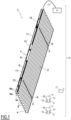
- This installation 100 comprises an opening, window or door, equipped with a screen 2 belonging to a screening device 1, in accordance with a first embodiment of the invention, in the example a screening device 1 of the type Venetian blind forming a slatted blind.
- the concealment device 1 may be, in particular, a pleated blind, a rolling shutter, a rolling gate, a gate or a door.
- the concealment device 1 is preferably placed outside the building.
- the concealment device 1 is arranged inside the building.
- the concealment device 1 comprises blades 3, in particular orientable.
- the concealment device 1 further comprises a load bar 4.
- the screen 2 is formed of the blades 3 and of the load bar 4.
- the load bar 4 makes it possible to exert a tension on the screen 2.
- the load bar 4 is fixed at a lower end of the screen 2, in particular in an assembled configuration of the concealment device 1 in the installation 100.
- the screen 2 comprises a final blade replacing the load bar 4, the latter can be weighted.
- the dimming device 1 comprises drive cords 5 configured to allow vertical movement of the slats 3 and the load bar 4.
- the drive cords 5 can also be called laces.
- the blades 3 respectively comprise openings, not shown, for the passage of each drive cord 5.
- the concealment device 1 further comprises orientation cords 6 configured to allow the orientation of the slats 3.
- the orientation cords 6 are also called ladders.
- each blade 3 of the screen 2 rests on a part of orientation cord 6, in particular horizontal and which can be called a bar, connecting two strands of orientation cord 6, in particular vertical.
- the orientation cords 6 make it possible to guarantee a regular vertical spacing of the blades 3 of the screen 2.
- the orientation of the slats 3 makes it possible, in particular, to adjust the brightness inside a room of the building.
- the concealment device 1 comprises two slides. Each of the slides is arranged along one side of the screen 2 of the concealment device 1. The slides are configured to cooperate with the slats 3 of the screen 2, so as to guide the slats 3, during deployment and folding screen 2.
- the guiding of the blades 3 is carried out by two cables.
- Each of the cables is arranged along one side of the screen 2 of the concealment device 1.
- the occultation device 1 comprises a motorized drive device 7.
- the motorized drive device 7 comprises at least one electromechanical actuator 8.
- the electromechanical actuator 8 is configured to drive, in other words drives, the screen 2 in displacement.
- the electromechanical actuator 8 makes it possible to lower or raise the blades 3 and the load bar 4, in other words to deploy or fold the screen 2, according to a vertical movement.
- the electromechanical actuator 8 also makes it possible to orient the blades 3.
- the occultation device 1 further comprises a rail 9, inside which is arranged the motorized drive device 7, in particular the electromechanical actuator 8, in particular in an assembled configuration of the occultation device 1.
- the rail 9 is arranged, in other words is configured to be arranged, above the screen 2, in particular in the assembled configuration of the concealment device 1.
- the rail 9 is arranged above the opening of the building, or else in the upper part of the opening of the building.
- the rail 9 comprises at least one bottom wall 9a and two side walls 9b.
- the rail 9 has a U-shaped section.
- the motorized drive device 7 further comprises a plurality of winders.
- the reels are configured to wind and unwind the drive cords 5, so as to drive the vertical movement of the blades 3 and the load bar 4.
- the motorized drive device 7 comprises two winders, not visible on the figure 1 .
- the number of winders is not limiting and may be different, in particular greater than two.
- the reels are arranged inside the rail 9.
- the drive cords 5 are connected, on the one hand, to the load bar 4 and, on the other hand, to the reels.
- each drive cord 5 is connected to the load bar 4 and the upper end of each drive cord 5 is connected to one of the reels.
- the motorized drive device 7 comprises tilting devices 13, generally referred to as “tilters”. Each reel is respectively arranged inside a rocker 13. This is why the reels are not visible to the figure 1 .
- rockers 13 are arranged, in other words are configured to be arranged, inside the rail 9, in particular in the assembled configuration of the concealment device 1.
- the motorized drive device 7 comprises two rockers 13.
- the number of rockers is not limiting and may be different, in particular strictly greater than two. In the case where the number of rockers is greater than or equal to two, the electromechanical actuator can be placed between two of the rockers.
- each rocker 13 is arranged on either side of the electromechanical actuator 8.
- each rocker 13 is arranged near one end of the rail 9, in the longitudinal direction thereof.
- the rockers 13 are configured to drive in rotation, over a range of limited angle of rotation value, the orientation cords 6, so as to orient the blades 3.
- the motor drive device 7, in particular the electromechanical actuator 8, is controlled by a control unit.
- the control unit is configured to control, i.e. controls, the motorized drive device 7, in particular the electromechanical actuator 8.
- the control unit can be, for example, a local control unit 14 or a central control unit 15.
- the local control unit 14 can be connected, in a wired or wireless connection, with the central control unit 15.
- the central control unit 15 can control the local control unit 14, as well as other units similar local control units distributed throughout the building.
- the motorized drive device 7 is preferably configured to execute the displacement commands, in particular for ascent or descent and, possibly, orientation, of the screen 2 of the concealment device 1, which can be issued, in particular , by the local control unit 14 or the central control unit 15.
- the installation 100 and, more particularly, the concealment device 1 comprises either the local control unit 14, or the central control unit 15, or the local control unit 14 and the central control unit 15 .
- Means for controlling the electromechanical actuator 8, allowing the movement of the screen 2 of the screening device 1 as well as the orientation of the blades 3 of the screen 2, comprise at least one electronic control unit 19 illustrated in figure 3 And 4 .
- the electronic control unit 19 is able to put an electric motor 18 of the electromechanical actuator 8 into operation and, in particular, to allow the supply of electric energy to the electric motor 18.
- the electric motor 18 can be of the electronically commutated brushless type, also called “BLDC” (acronym of the Anglo-Saxon term BrushLess Direct Current) or “synchronous with permanent magnets”, of the asynchronous type or of the direct current type.
- BLDC electronically commutated brushless type
- synchronous with permanent magnets of the asynchronous type or of the direct current type.
- the electronic control unit 19 is integrated into the electromechanical actuator 8.
- the electronic control unit 19 controls, in particular, the electric motor 18, so as to open or close the screen 2, as well as so as to orient the blades 3 of the screen 2, as described above.
- the electronic control unit 19 comprises a printed circuit board 42, visible to figure 4 And 5 and which supports various electronic components necessary for controlling the electric motor 18, including those mentioned below.
- the electronic control unit 19 may comprise several printed circuit boards.
- the electronic control unit 19 comprises at least one communication module 49, in particular for receiving control orders, the control orders being transmitted by an order transmitter, such as the local control unit 14 or control unit 15, these commands being intended to control the motorized drive device 7.
- the communication module 49 of the electronic control unit 19 is of the wired type, in other words allows the reception and, possibly, the transmission of control commands transmitted by wired means.
- the electronic control unit 19, the local control unit 14 and/or the central control unit 15 can be in communication with a weather station, not shown, located inside the building or remote to the building. outside the building, including, in particular, one or more sensors that can be configured to determine, for example, a temperature, a luminosity or even a wind speed, in the case where the weather station is remote outside the building.
- the electronic control unit 19, the local control unit 14 and/or the central control unit 15 can also be in communication with a server 27, so as to control the electromechanical actuator 8 according to data made available remotely via a communication network, in particular an Internet network that can be connected to the server 27.
- a communication network in particular an Internet network that can be connected to the server 27.
- the electronic control unit 19 can be controlled from the local 14 or central 15 control unit.
- the local 14 or central 15 control unit is provided with a control keyboard.
- the control keyboard of the local 14 or central 15 control unit comprises one or more selection elements 50 and, optionally, one or more display elements 51.
- the selection elements can be push buttons or sensitive keys
- the display elements can be light-emitting diodes, an LCD display (acronym of the Anglo-Saxon term “Liquid Crystal Display”) or TFT (acronym of the Anglo-Saxon term “Thin Film Transistor”).
- the selection and display elements can also be produced by means of a touch screen.
- the local 14 or central 15 control unit comprises at least one communication module 48.
- the communication module 48 of the local 14 or central 15 control unit is configured to transmit, in other words sends, control commands, in particular by wired means.
- the communication module 48 of the local 14 or central 15 control unit can also be configured to receive, in other words receives, control commands, in particular via the same means.
- the communication module 48 of the local 14 or central 15 control unit is hereinafter called the first communication module.
- the module of communication 49 of the electronic control unit 19 is subsequently called the second communication module.
- the first communication module 48 of the local 14 or central 15 control unit is configured to communicate, in other words communicates, with the second communication module 49 of the electronic control unit 19.
- the first communication module 48 of the local 14 or central 15 control unit exchanges control commands with the second communication module 49 of the electronic control unit 19, either unidirectionally or bidirectionally.
- the local control unit 14 is a control point, which can be fixed or mobile.
- a fixed control point can be a control box intended to be fixed on a facade of a wall of the building or on a face of the fixed frame of a window or a door.
- a nomadic control point can be a remote control, a smart phone or a tablet.
- the local 14 or central 15 control unit further comprises a controller 52.
- the control means of the electromechanical actuator 8 comprise hardware and/or software means.
- the hardware means may comprise at least one microcontroller 29, as illustrated in figure 4 .
- the motorized drive device 7, in particular the electronic control unit 19, is preferably configured to execute movement control commands, in particular deployment or folding of the screen 2 of the concealment device 1 , as well as the orientation of the slats 3. These commands can be issued, in particular, by the local control unit 14 or by the central control unit 15.
- the motorized drive device 7 can be controlled by the user, for example by receiving a control command corresponding to a press on the or one of the selection elements 50 of the local control unit 14 or center 15.
- the motorized drive device 7 can also be controlled automatically, for example by receiving a control command corresponding to at least one signal coming from at least one sensor, not shown, and/or to a signal coming from a clock, not shown.
- the sensor and/or the clock can be integrated in the local control unit 14 or in the central control unit 15.
- the sensor and/or the clock can also be considered as corresponding to a control unit, in particular a local control unit 14.
- the electromechanical actuator 8 includes, among other things, the electric motor 18 and the electronic control unit 19.
- the electric motor 18 comprises a stator 182, a rotor 184 and a rotation shaft 186.
- the rotation shaft 186 is integral with the rotor 184.
- the rotation shaft 186 is configured to be driven in rotation, in other words is driven in rotation, around an axis of rotation X.
- the rotation shaft 186 protrudes at the two opposite ends of the electromechanical actuator 8 and constitutes an output shaft for this electromechanical actuator 8.
- the rotation shaft 186 is axially limited to the length of the electric motor 18 and connected to two output shafts of the electromechanical actuator 8 which protrude respectively at each of the ends of the latter, or even at a output shaft which protrudes only at one end of it.
- stator 182 and the rotor 184 are positioned coaxially around the axis of rotation X.
- the rotation shaft 186 is integrated or coupled to the rotor 184.
- the axis of rotation X is also the axis of rotation of the reels, in a mounted configuration of the motor drive device 7.
- the electromechanical actuator 8 makes it possible to move the screen 2 of the screening device 1, in particular according to a vertical movement, as well as to orient the blades of the screen 2.
- the electromechanical actuator 8 further comprises an electrical power cable 10.
- the electromechanical actuator 8 is configured to be supplied, in other words is supplied, with electrical energy by a main electrical power source 54, via the electrical power cable 10.
- the main electrical power source 54 can be a mains electrical power supply network or a battery, which can be recharged, for example, by a photovoltaic panel or a charger, not shown.
- the electromechanical actuator 8 further comprises a casing 17, in particular tubular.
- the electric motor 18 and the electronic control unit 19 are housed, in other words mounted, inside the casing 17, in particular in an assembled configuration of the electromechanical actuator 8.
- the casing 17 of the electromechanical actuator 8 comprises a plurality of sections, including at least three sections designated by the references 17A, 17B, 17C. He's from parallelepipedic shape and, more particularly, has a section of generally rectangular shape.
- the housing 17 of the electromechanical actuator 8 is cylindrical in shape with a circular section.
- the electromechanical actuator 8 further comprises at least one reducer 12.
- the reducer 12 comprises at least one reduction stage.
- the reduction stage may be an epicyclic type gear train.
- the type and number of reduction stages of the reducer are not limiting.
- the reduction stages can be, for example, two or three in number.
- Each end of the rotation shaft 186 carries a sleeve 187 for coupling to a drive shaft 11 of one of the winders.
- Each winder is thus driven in rotation, at one of the rockers 13, by one of the drive shafts 11 coupled with the output shaft 186 of the electromechanical actuator 8.
- the electromechanical actuator 8 further comprises a brake 46, as illustrated in picture 3 .
- the brake 46 can be a spring brake, a cam brake, a magnetic brake or an electromagnetic brake.
- the reducer 12 and the brake 46 are also housed in the casing 17 of the electromechanical actuator 8.
- the reducer 12 and the brake 46 are arranged outside the casing 17 of the electromechanical actuator 8.
- the electromechanical actuator 8 further comprises an end-of-travel detection device 21.
- the screen 2 comprises the plurality of blades 3, including a first blade 3h.
- the first blade 3h faces the bottom wall 9a of the rail 9, in particular in the assembled configuration of the screening device 1.
- the first blade 3h of the screen 2 corresponds to the upper blade 3 of the screen 2.
- a high position in particular a safety position, corresponds to pressing the first slat 3h of the screen 2 against an element of the end-of-travel detection device 21.
- the end-of-travel detection device 21 makes it possible, in particular, to determine when the upper end-of-travel position of the screen 2 has been reached.
- the end-of-travel detection device 21 is generally called a “mushroom”.
- a high limit position in particular for operation, corresponds to a predetermined high limit position, in particular programmed by means of the electronic control unit 19 and determined by means of a counting device 35.
- a bottom end-of-travel position corresponds to a predetermined bottom end-of-travel position, in particular programmed by means of the electronic control unit 19 and determined by means of the counting device 35, or when of the load bar 4 against a threshold of the opening of the building, or even to the complete deployment of the screen 2.
- the counting device 35 can be of the magnetic type.
- Such a counting device 35 comprises at least one wheel, which can be assembled on the rotation shaft 186 of the electric motor 18, and Hall effect sensors, which are not shown in detail.
- the type of counting device 35 is not limiting and may be different, in particular of the optical type or of the time type and produced through the microcontroller 29 of the electronic control unit 19.
- the end-of-travel detection device 21 comprises a member 22, movable inside a casing 17D formed by a part of the casing 17, in the one-piece example with the part 17A of the casing 17, and, possibly , an elastic return member 23 formed by a coil spring.
- the housing 17D of the end-of-travel detection device 21 can be formed by a part of the casing 17 attached to the part 17A of the casing 17 and fixed to the latter, for example by means of fastening by screwing or by elastic snap-fastening.
- the housing 17D of the end-of-travel detection device 21 is cylindrical and has an interior section of generally circular shape.
- the housing 17D of the end-of-travel detection device 21 is of parallelepiped shape.
- the elastic return member 23 may be different from a coil spring, for example a block of elastically deformable material.
- the member 22 is movable in translation along an axis A22 radial to the axis of rotation X.
- the member 22 is provided with a rectilinear rod 22A which is engaged in a hollow tube 17E, formed by a part of the casing 17 and which is centered on axis A22.
- the translational movement of member 22 along axis A22 is guided by the cooperation of shapes of parts 17E and 22A.
- the member 22 comprises a head 22B projecting from the casing 17D and intended to receive the first blade 3h in support, when the screen 2 reaches its upper end-of-travel position. To do this, the housing 17D and the member 22 are engaged from above in a slot, not shown, formed in the bottom wall 9a of the rail 9. When it is pushed back by the first blade 3h along the axis A22, the member 22 actuates a switch 43 carried by the printed circuit board 42. This allows the electronic control unit 19 to detect that the screen 2 is in the upper limit position.
- the casing 17 is made at least in part from a metallic material.
- the material of the housing of the electromechanical actuator is not limiting and can be different. It may, in particular, be a plastic material.
- the electronic control unit 19 is configured to control, in other words control, the electric motor 18 in a first mode of operation, called control, normal or use, where it supplies electrical energy to the electric motor 18 according to the upward or downward movements of screen 2, as well as orientation movements of slats 3 of screen 2.
- the electronic control unit 19 is also configured to control, in other words control, the electric motor 18 in a second mode of operation, in particular learning, configuration, programming or adjustment, which implements the counting 35 to determine and memorize one or more end positions of the screen 2.
- the electromechanical actuator 8 further comprises a tilt control device 25.
- the tilt control device 25 is configured to switch, in other words toggle, the electronic control unit 19 between the first and second operating modes.
- the tilting control device 25 is based on a magnetic detection technology, more reliable than the purely mechanical tilting control devices of the prior art, which makes it possible to know precisely when the electronic control unit 19 must switch between the first and second modes of operation.
- the tilting control device 25 is adjacent to the end-of-travel detection device 21.
- the tilting control device 25 can be inserted in the same slot made in the bottom wall 9a of the rail 9 as that of the end-of-travel detection device 21 or in an adjacent slot made in the bottom wall 9a of the rail 9 to that of the end-of-travel detection device 21, while being accessible from below this rail 9.
- the tilting control device 25 is positioned in a manner comparable to the purely mechanical devices of the prior art, so that its incorporation into the concealment device 1 in accordance with the invention does not fundamentally change the working habits of an operator accustomed to equipment already present on the market and comprising a purely mechanical tilting control device.
- the tilting control device 25 comprises a flap 26, visible in perspective from two different angles at the figure 6 .
- the shutter 26 is pivotally mounted, around an axis A25, in a housing 17F, formed by a part of the casing 17, in the one-piece example with the part 17A of the casing 17.
- the housing 17F of the tilting control device 25 may be formed by a part of the casing 17 attached to the part 17A of the casing 17 and fixed to the latter, for example by means of fixing elements by screwing or snap-fastening.
- Housing 17F may also be referred to as the first housing and housing 17D may also be referred to as the second housing.
- axis A25 of articulation of flap 26 with respect to housing 17F is parallel to axis of rotation X, in particular in the assembled configuration of electromechanical actuator 8.
- the axis A25 can be oriented differently, in particular be perpendicular to the axis of rotation X.
- the flap 26 is made of a non-magnetic material.
- the flap 26 comprises a first panel 262 and a second panel 264.
- first and second panels 262, 264 each extend along a plane P262, P264.
- the planes P262, P264 define between them an angle ⁇ 26 around an axis A26 of the flap 26 which coincides with the axis A25 in the mounted configuration of the flap 26 in the housing 17F.
- Note B17 an edge, called “free", of the housing 17F, opposite the part 17A of the housing 17. This edge B17 delimits an access opening to the internal volume of the housing 17F, in which is housed the shutter 26.
- this edge B17 has a generally rectangular shape, with rounded corners, which corresponds to the section of the housing 17F in its part farthest from the part 17A of the casing 17.
- the axis A25 is parallel to the small sides of the edge B17 and is arranged at equal distance from these small sides.
- the inserts A) and B) represent two stable operating positions of the tilt control device 25.
- an outer surface S264 of the second panel 264 of the flap 26 is flush with the edge B17 in a first, so-called extreme, position of the flap 26 shown in figures 2 to 4 and on insert A) of the figure 5 .
- an outer surface S262 of the first panel 262 of the flap 26 is flush with this same edge B17 in a second position, called extreme, of the flap 26 shown on the insert B) of the figure 5 .
- the flap 26 can take all the intermediate positions between the first position and the second position, by rotating around the axis A25.
- the sum of the angles ⁇ 26 and ⁇ 26 is equal to 180°.
- the first panel 262 is provided, on its outer surface S262, with a first recessed housing 263.
- this first recessed housing 263 makes it possible to receive the tip of a tool, such as a screwdriver, when an operator exerts on the first panel 262 a pivoting force around the axes A25, A26, as represented by the arrow F1 on insert B) of the figure 5 , so as to tilt the flap 26 from its second position to its first position.
- a tool such as a screwdriver
- the second panel 264 is provided, on its external surface S264, with a second recessed housing 265.
- this second recessed housing 265 makes it possible to receive the end of a tool, such as a screwdriver, when an operator exerts on the second panel 264 a pivoting force around the axes A25, A26, as represented by the arrow F2 on insert A) of the figure 5 , so as to tilt the flap 26 from its first position to its second position.
- a tool such as a screwdriver
- first and second panels 262, 264 have no first and second recessed housings 263, 265.
- the flap 26, in particular the second panel 264, comprises a housing 266, in which is arranged a permanent magnet 27, which belongs to the tilting control device 25.
- the permanent magnet 27 is completely received in the housing 266.
- part of the permanent magnet 27 may project from the housing 266.
- the tilting control device 25 comprises a magnetic sensor 28, in particular Hall effect.
- This magnetic sensor 28 is mounted inside the casing 17, near the casing 17F, more precisely near an interior surface of this casing 17F.
- This magnetic sensor 28 is supported by the printed circuit board 42, or by another support, which also belongs to the electronic control unit 19.
- the magnetic sensor 28 is able to signal to the microcontroller 29 that the tilting control device 25 has been actuated, due to the application of one of the forces represented by the arrows F1, F2.
- the internal shape of the box 17F is compatible with the pivoting of the flap 26, in particular of the second panel 264, between its first and second positions represented on the two inserts A, B of the figure 5 .
- the inner surface of the housing 17F comprises a section 172 in the form of a cylinder with a circular section centered on the axis A25 and whose radius is greater than or equal to the largest dimension of the second panel 264 measured radially to the axis A26.
- the flap 26 includes at least one retaining tab in position 268 of the flap 26.
- the flap 26, in particular the first panel 262, comprises a single retaining tab at position 268.
- the housing 17F comprises a first stop and a second stop.
- the first stop is configured to cooperate, in other words cooperates, with the retaining tab in position 268, when the flap 26 is in the first position.
- the second stop is configured to cooperate, in other words cooperates, with the retaining tab in position 268, when the flap 26 is in the second position.
- the housing 17F in particular its inner surface, comprises, on the one hand, a notch 174 defining the first abutment of the housing 17F and, on the other hand, a re-entrant corner 176 and a recess 178 defining the second abutment of the housing 17F.
- the retaining tab in position 268 is configured to cooperate, in other words cooperates, with the notch 174 in the first position of the flap 26 and with the re-entrant corner 176 and the recess 178 in the second position of this flap 26.
- the retaining tab in position 268 is elastically deformable.
- position retaining tab 268 includes a free end 268A.
- the position represented on insert A of the figure 5 is a stable position.
- the permanent magnet 27 does not risk being moved accidentally around the axis A25. No parasitic movement of the permanent magnet 27 around the axis A25 therefore risks being detected by the magnetic sensor 28.
- the retaining tab in position 268 further comprises a bead 268B.
- the free end 268A of the retaining tab in position 268 is engaged in the re-entrant corner 176 and the bead 268B of the retaining tab in position 268 is engaged in the recess 178.
- the position represented on the insert B) of the figure 5 is also a stable position.
- the permanent magnet 27 does not risk being moved accidentally around the axis A25. No parasitic movement of the permanent magnet 27 around the axis A25 therefore risks being detected by the magnetic sensor 28.
- the shutter 26 can be described as "bistable", because the two positions represented on the inserts A) and B) of the figure 5 are stable positions, in which the flap 26 is immobilized in rotation around the axis A25 by pressing the retaining tab in position 268 on the internal surface of the housing 17F, more particularly at the level of the concave internal reliefs 174, 176, 178.
- the flap 26 comprises a plurality of retaining tabs in position 268.
- the flap 26 can be equipped with a first retaining lug in position 268, configured to bear, in other words bearing, on the housing 17F, when the latter is in its first position and with a second retaining lug in position 268, configured to bear, in other words bearing, on the housing 17F, when it is in its second position, the second retaining lug in position 268 being different from the first retaining lug in position 268.
- the first retaining tab at position 268 is configured to cooperate, i.e. cooperates, with the notch 174.
- the second retaining tab at position 268 is configured to cooperate, i.e. cooperates, with the recess 178.
- the position of the permanent magnet 27 can be identified by the magnetic sensor 28, for example by detecting the distance and/or the relative orientation(s) of the South pole or of the North pole of the permanent magnet 27 with respect to the sensor. magnetic 28.
- This position of the permanent magnet 27 detected by the magnetic sensor 28 can be stored in a memory 47, in particular non-volatile, of the electronic control unit 19, in particular of the microcontroller 29, in the form of a parameter representative of this position.
- This parameter can be binary, for example equal to 0 or 1, to represent either the position of insert A) or the position of insert B) of the figure 5 .
- this parameter can be proportional and correspond to a distance or an angle value measured between the magnetic sensor 28 and the South or North pole of the permanent magnet 27.
- the electromechanical actuator 8 further comprises a mechanical member 126.
- the mechanical member 26 is configured to deliver, in other words delivers, sound information, when the shutter 26 pivots between its first position and its second position, and/or vice versa.
- the mechanical member 126 is an elastic return element, in particular a spring.
- the mechanical member 126 is interposed between the flap 26, which is comparable to the flap 26 of the first embodiment, and a part 17F1, in particular the bottom, of the box 17F.
- the shutter 26 and the box 17F belong to the tilt control device 25.
- the mechanical member 126 is housed, in other words is configured to be housed, inside the casing 17F, in particular in the assembled configuration of the electromechanical actuator 8.
- the flap 26 further comprises two retaining lugs 269.
- the mechanical member 126 is mounted, in other words is configured to be mounted, on the two retaining lugs 269 of the flap 26, in particular in the assembled configuration of electromechanical actuator 8.
- the mechanical member 126 comes into abutment, in other words is configured to come into abutment, against the part 17F1 of the housing 17F, when the flap 26 pivots between its first position and its second position, and/or vice versa.
- the mechanical member 126 when tilting the flap 26 between its first and second positions, or vice versa, defined as in the first embodiment, the mechanical member 126 is compressed and then suddenly relaxes, making a "click" noise which is perceived by the user.
- the user is informed by the sound information delivered by the mechanical member 126 that the flap 26 has actually changed position, from its first position to its second position, or vice versa.
- the mechanical member 126 can deliver such information when the flap 26 pivots from its first position to its second position, from its second position to its first position or in both cases.
- the mechanical member 126 is metallic, for example made of steel.
- the mechanical member 126 can be made of another material, in particular composite.
- the mechanical member 126 is in the form of a loop.
- the mechanical member 126 comprises a rectilinear part 126A intended to be mounted on the two retaining lugs 269 of the flap 26, like a hinge.
- the mechanical member 126 comprises two curved ends 126B, 126C, between which is defined a support portion of the mechanical member 126 against the part 17F1 of the housing 17F.
- the mechanical member 126 may have a different shape or be replaced by another mechanical member, such as, for example, a clip or a tongue, capable of delivering sound information to the user when the flap 26 pivots between its first and second positions, or vice versa.
- This method is implemented by means of the electronic control unit 19 and, in particular, of the microcontroller 29.
- the method includes, initially, a first step 1001 of powering up the electromechanical actuator 8.
- a first value V1 of the parameter representative of the position of the permanent magnet 27 detected by the magnetic sensor 28 has been stored in the memory 47 of the electronic control unit 19.
- This storage of the first value V1 could be implemented, in particular, during the last previous power-up of the electromechanical actuator 8.
- This first value V1 is stored in memory 47, including when the electrical power supply to electromechanical actuator 8 is stopped.
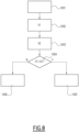
- the method comprises a second step 1002 of reading the first value V1, in the memory 47 of the electronic control unit 19.
- the second reading step 1002 can be implemented following the first step 1001 of powering up the electromechanical actuator 8.
- the storage of the first value V1 is implemented during a step of powering up the electromechanical actuator 8 prior to the present step of powering up 1001.
- the method comprises a third step 1003 of detecting the position of the permanent magnet 27 by the magnetic sensor 28.
- a second value V2 of the same parameter than that of the first value V1 is determined during this third step 1003 of detection. Then, this second value V2 is stored in the memory 47 of the electronic control unit 19.
- the third step 1003 of detection can be implemented following the first step 1001 of powering up the electromechanical actuator 8.
- the order of the second and third steps 1002, 1003 can be reversed or they can be executed simultaneously.
- the method comprises a fourth step 1004 of comparing the first value V1, read during the second step 1002 of reading, with the second value V2, determined during the third step 1003 of detection.
- the method comprises a first step 1005 of operating the electronic control unit 19 in the first operating mode and a second step 1006 of operating the electronic control unit 19 in the second operating mode.
- the method implements implements the first step 1005 of putting the electronic control unit 19 into operation in the first mode of operation.
- the tilting control device 25 has not been actuated.
- the first step 1005 of putting the electromechanical actuator 8 into operation is executed.
- the method implements implements the second step 1006 of putting the electronic control unit 19 into operation in the second mode of operation.
- the tilting control device 25 has been actuated, passing from one of the positions shown in figure 5 to the other of these positions.
- the second step 1006 of putting into operation, in other words of adjustment, of the actuator electromechanical 8 is executed.
- the electromechanical actuator 8 can be controlled in the second operating mode by the electronic control unit 19, in particular in an operating mode making it possible to adjust at least one of the end-of-travel positions.
- the tilting control device can be easily integrated into the electromechanical actuator.
- the retaining lug in the position of the shutter relative to the housing guarantees bistable operation of the tilting control device.
- the tilting control device makes it possible to reliably control the tilting of the electronic control unit between at least its two operating modes.
- the fact of mounting the permanent magnet on the flap makes it possible to produce the tilting control device in a compact form and guarantees reliable detection of its activation by an operator.
- the motorized drive device 7 comprises, in addition to a plurality of first reels of the drive cords 5, a plurality of second reels of the orientation cords 6.
- the cords drive 5 are connected, on the one hand, to the load bar 4 and, on the other hand, to the first winders.
- the orientation cords 6 are connected, on the one hand, to the load bar 4 and to the slats 3 and, on the other hand, to the second winders.
- the lower end of each drive cord 5 is connected to the load bar 4 and the upper end of each drive cord 5 is connected to one of the first winders, in particular in the assembled configuration of the concealment device 1 in the installation 100.
- each orientation cord 6 is connected to the load bar 4 and the upper end of each orientation cord 6 is connected to one of the second reels, in particular in the assembled configuration of the screening device 1 in the installation 100.
- the first and second reels are arranged inside the rail 9.
- the motorized drive device 7 comprises two chains for driving and orienting the slats 3 of the screen 2, replacing the drive cords 5 and the orientation cords 6.
- each chain is arranged inside one of the wings, arranged along one side of the screen 2 of the concealment device 1.
- the second communication module 49 of the electronic unit of control 19 is configured to receive, in other words receives, and, possibly, to transmit, in other words transmits, control commands transmitted by wireless means, in particular, radio control commands.
- the first communication module 48 of the local 14 or central 15 control unit is configured to send, in other words sends, and, optionally, to receive, in other words receives, control commands, in particular by means wireless, for example radio.
- the magnetic sensor 28 can be different from a Hall effect sensor. It may be an inductive sensor or a magnetoresistive sensor, which may be based, for example, on a so-called “GMR” technology (acronym of the English expression “Giant Magneto Resistance”).
- a play is visible between the free end 268A of the retaining tab in position 268 and the edge of the notch 174 or the edge of the inside corner 176 and between the bead 268B of the retaining tab in position 268 and the edge of the recess 178.
- at least one of the parts 268A, 268B of the retaining lug in position 268 can be in contact with the edge of one of these concave internal reliefs 174, 176, 178 in the first and/or in the second position of the flap 26.
- the switching control device 25 can be configured to switch the electronic control unit 19 to another mode of operation.
- This other mode of operation of the electronic control unit 19 can be in addition to or in replacement of the second mode of operation, called "parameterization" of one or more end-of-travel positions of the screen 2.
- the predetermined sequence of shutter 26 switchings to enter one of the operating modes can be defined according to the number of successive switchings and/or a duration of each switching of the shutter 26.
Abstract
Un actionneur électromécanique comprend un moteur électrique, une unité électronique de contrôle (19), et un dispositif de commande de basculement (25) pour basculer l'unité électronique de contrôle (19) entre des premier et deuxième modes de fonctionnement. Le dispositif de commande de basculement (25) comprend un volet (26), pivotant par rapport à un boîtier (17F) entre des première et deuxième positions, un aimant permanent (27), monté sur le volet (26), et un capteur magnétique (28) pour détecter une position de l'aimant permanent (27). Le volet (26) comprend une patte de retenue en position (268) du volet (26), maintenue en position par rapport au boîtier (17F) dans chacune des première et deuxième positions du volet (26), de sorte que chacune des première et deuxième positions du volet (26) est stable.An electromechanical actuator includes an electric motor, an electronic control unit (19), and a toggle control device (25) for toggling the electronic control unit (19) between first and second modes of operation. The tilt control device (25) includes a flap (26), pivotable relative to a housing (17F) between first and second positions, a permanent magnet (27), mounted on the flap (26), and a sensor magnet (28) to detect a position of the permanent magnet (27). The flap (26) includes a position retaining tab (268) of the flap (26), held in position relative to the housing (17F) in each of the first and second positions of the flap (26), such that each of the first and second position of the flap (26) is stable.
Description
La présente invention concerne un actionneur électromécanique d'un dispositif d'occultation, autrement dit un actionneur électromécanique pour un dispositif d'occultation.The present invention relates to an electromechanical actuator of a dimming device, in other words an electromechanical actuator for a dimming device.
La présente invention concerne également un dispositif d'occultation comprenant un rail et un écran. L'écran est entraîné en déplacement par un tel actionneur électromécanique disposé à l'intérieur du rail.The present invention also relates to a screening device comprising a rail and a screen. The screen is driven in displacement by such an electromechanical actuator arranged inside the rail.
La présente invention concerne, en outre, un procédé de commande d'un tel actionneur électromécanique.The present invention further relates to a method for controlling such an electromechanical actuator.
De manière générale, la présente invention concerne le domaine des dispositifs d'occultation comprenant un dispositif d'entraînement motorisé mettant en mouvement un écran, entre au moins une première position et au moins une deuxième position.In general, the present invention relates to the field of screening devices comprising a motorized drive device that sets a screen in motion between at least a first position and at least a second position.
Un dispositif d'entraînement motorisé comprend un actionneur électromécanique d'un élément mobile de protection solaire ou de fermeture, tel qu'un store, en particulier à lames, un volet, une porte, une grille, un rideau ou tout autre matériel équivalent, appelé par la suite écran.A motorized drive device comprises an electromechanical actuator for a mobile sun protection or closing element, such as a blind, in particular a slatted blind, a shutter, a door, a grille, a curtain or any other equivalent material, hereafter called screen.
Un type particulier de dispositif d'occultation est celui des stores vénitiens dans lesquels un store est formé de lames dont le déplacement en hauteur et, éventuellement, l'orientation, peuvent être commandés au moyen d'un actionneur électromécanique. Avec ce type de matériel, il est connu d'équiper l'actionneur électromécanique d'un dispositif de détection de l'atteinte d'une position de fin de course haute de l'écran, ce dispositif de détection pouvant comprendre un organe mobile qui reçoit en appui une lame supérieure du store, comme décrit dans le document
D'autre part, un actionneur électromécanique doit pouvoir être commandé dans un mode de fonctionnement normal, où il entraîne l'écran entre des positions de fin de course haute et basse et un mode de fonctionnement d'apprentissage qui permet de définir ces positions de fin de course haute et basse. Une unité électronique de contrôle est généralement utilisée à cet effet et il est connu d'utiliser un dispositif mécanique pour commander le basculement de cette unité électronique de contrôle entre ces deux modes de fonctionnement. Des dispositifs mécaniques de ce type sont connus des documents
Ces dispositifs mécaniques comprennent un nombre de pièces relativement important, dont des pignons. Ils sont complexes à installer et d'une fiabilité perfectible. D'un autre côté, les installateurs ont l'habitude d'agir sur de tels dispositifs mécaniques dont ils connaissent généralement l'emplacement et qu'ils ont l'habitude de manipuler sans précaution particulière. Par ailleurs, remplacer un dispositif mécanique par un interrupteur magnétique s'avère complexe du fait de l'encombrement des interrupteurs magnétiques connus, qui seraient difficiles à intégrer dans un actionneur électromécanique de taille habituelle pour le marché des dispositifs d'occultation. En outre, un interrupteur magnétique n'est généralement pas stable en position, ce qui peut s'avérer problématique. En effet, les vibrations induites lors du fonctionnement d'un dispositif d'occultation risquent de faire basculer un tel interrupteur entre ses deux positions.These mechanical devices comprise a relatively large number of parts, including pinions. They are complex to install and of perfectible reliability. On the other hand, installers are used to working on such mechanical devices which they generally know the location and are used to handling without special precautions. Furthermore, replacing a mechanical device with a magnetic switch proves to be complex due to the size of the known magnetic switches, which would be difficult to integrate into an electromechanical actuator of the usual size for the occultation device market. Also, a magnetic switch is generally not stable in position, which can be problematic. Indeed, the vibrations induced during the operation of a screening device risk causing such a switch to switch between its two positions.
C'est à ces problèmes qu'entend plus particulièrement remédier l'invention en proposant un actionneur électromécanique d'un dispositif d'occultation dont un dispositif de commande de basculement de son unité électronique de contrôle, entre des premier et deuxième modes de fonctionnement, est d'une construction simple, fiable et compacte et qui est stable en position.It is these problems that the invention more particularly intends to remedy by proposing an electromechanical actuator for a concealment device including a control device for switching its electronic control unit between first and second modes of operation, is of simple, reliable and compact construction and is stable in position.
On connaît également le document
A cet effet, la présente invention concerne, selon un premier aspect, un actionneur électromécanique d'un dispositif d'occultation,
l'actionneur électromécanique comprenant au moins :
- un moteur électrique,
- une unité électronique de contrôle, l'unité électronique de contrôle étant configurée pour commander le moteur électrique dans un premier mode de fonctionnement et au moins dans un deuxième mode de fonctionnement,
- un carter, dans lequel sont logés le moteur électrique et l'unité électronique de contrôle,
- un arbre de sortie, l'arbre de sortie étant monté rotatif autour d'un axe de rotation, et
- un dispositif de commande de basculement, le dispositif de commande de basculement étant configuré pour basculer l'unité électronique de contrôle entre les premier et deuxièmes modes de fonctionnement.
the electromechanical actuator comprising at least:
- an electric motor,
- an electronic control unit, the electronic control unit being configured to control the electric motor in a first operating mode and at least in a second operating mode,
- a casing, in which the electric motor and the electronic control unit are housed,
- an output shaft, the output shaft being rotatably mounted about an axis of rotation, and
- a switch control device, the switch control device being configured to switch the electronic control unit between the first and second modes of operation.
Le dispositif de dispositif de commande de basculement comprend :
- un boîtier,
- un volet, le volet étant monté pivotant autour d'un axe par rapport au boîtier, entre une première position et une deuxième position,
- un aimant permanent, l'aimant permanent étant monté sur le volet, et
- un capteur magnétique, le capteur magnétique étant configuré pour détecter une position de l'aimant permanent.
- a housing,
- a flap, the flap being pivotally mounted about an axis relative to the housing, between a first position and a second position,
- a permanent magnet, the permanent magnet being mounted on the flap, and
- a magnetic sensor, the magnetic sensor being configured to detect a position of the permanent magnet.
Selon l'invention, le volet comprend au moins une patte de retenue en position du volet, la ou l'une des pattes de retenue en position étant maintenue en position par rapport au boîtier dans chacune des première et deuxième positions du volet, de sorte que chacune des première et deuxième positions du volet est stable.According to the invention, the flap comprises at least one position-retaining tab of the flap, the or one of the position-retaining tabs being held in position relative to the housing in each of the first and second positions of the flap, so that each of the first and second positions of the flap is stable.
Ainsi, le dispositif de commande de basculement peut être facilement intégré à l'actionneur électromécanique. La patte de retenue en position du volet par rapport au boîtier garantit un fonctionnement bistable du dispositif de commande de basculement.Thus, the tilting control device can be easily integrated into the electromechanical actuator. The retaining lug in the position of the shutter relative to the housing guarantees bistable operation of the tilting control device.
De cette manière, le dispositif de commande de basculement permet de piloter de façon fiable le basculement de l'unité électronique de contrôle entre ses au moins deux modes de fonctionnement.In this way, the tilting control device makes it possible to reliably control the tilting of the electronic control unit between its at least two operating modes.
En outre, le fait de monter l'aimant permanent sur le volet permet de réaliser le dispositif de commande de basculement sous une forme compacte et garantit une détection fiable de son activation par un opérateur.In addition, the fact of mounting the permanent magnet on the flap makes it possible to produce the tilting control device in a compact form and guarantees reliable detection of its activation by an operator.
Selon des aspects avantageux mais non obligatoires de l'invention, un tel actionneur électromécanique peut incorporer une ou plusieurs des caractéristiques suivantes, prises selon toute combinaison techniquement admissible :
- La même patte de retenue en position est en appui contre le boîtier, lorsque le volet est dans la première position ou dans la deuxième position.
- Le boîtier comprend :
- une première butée, la première butée étant configurée pour coopérer avec la ou l'une des pattes de retenue en position, lorsque le volet est dans la première position, et
- une deuxième butée, la deuxième butée étant configurée pour coopérer avec la ou l'une des pattes de retenue en position, lorsque le volet est dans la deuxième position.
- Le volet est une pièce monobloc en matériau amagnétique.
- Le capteur magnétique est un capteur à effet Hall.
- Le volet comprend deux panneaux, chacun des deux panneaux étant affleurant avec un bord du boîtier dans l'une des première et deuxième positions du volet.
- L'actionneur électromécanique comprend, en outre, un dispositif de détection de fin de course, le dispositif de détection de fin de course étant configuré pour détecter l'atteinte d'une position de fin de course haute d'un écran du dispositif d'occultation entraîné en déplacement par l'actionneur électromécanique.
- Le dispositif de commande de basculement est adjacent au dispositif de détection de fin de course, le long d'un axe parallèle à l'axe de rotation.
- L'actionneur électromécanique comprend, en outre, un organe mécanique, l'organe mécanique étant configuré pour délivrer une information sonore, lorsque le volet pivote entre sa première position et sa deuxième position, et/ou inversement.
- L'organe mécanique est un élément de rappel élastique, l'organe mécanique étant interposé entre le volet et une partie du boîtier.
- The same position-retaining lug bears against the housing when the shutter is in the first position or in the second position.
- The box includes:
- a first stop, the first stop being configured to cooperate with the or one of the retaining lugs in position, when the shutter is in the first position, and
- a second abutment, the second abutment being configured to cooperate with the or one of the retaining lugs in position, when the shutter is in the second position.
- The flap is a one-piece piece of non-magnetic material.
- The magnetic sensor is a Hall effect sensor.
- The flap comprises two panels, each of the two panels being flush with an edge of the housing in one of the first and second positions of the flap.
- The electromechanical actuator further comprises an end-of-travel detection device, the end-of-travel detection device being configured to detect the reaching of a high end-of-travel position of a screen of the dimming driven in displacement by the electromechanical actuator.
- The tilt control device is adjacent to the end of stroke detection device, along an axis parallel to the axis of rotation.
- The electromechanical actuator further comprises a mechanical member, the mechanical member being configured to deliver sound information, when the shutter pivots between its first position and its second position, and/or vice versa.
- The mechanical member is an elastic return element, the mechanical member being interposed between the flap and a part of the housing.
La présente invention concerne, selon un deuxième aspect, un dispositif d'occultation, le dispositif d'occultation comprenant au moins :
- un rail,
- un écran, et
- un actionneur électromécanique conforme à l'invention et tel que mentionné ci-dessus, l'actionneur électromécanique étant disposé à l'intérieur du rail, l'écran étant entraîné en déplacement par l'actionneur électromécanique.
- a rail,
- a screen, and
- an electromechanical actuator according to the invention and as mentioned above, the electromechanical actuator being arranged inside the rail, the screen being driven in displacement by the electromechanical actuator.
La présente invention concerne, selon un troisième aspect, un procédé de commande d'un actionneur électromécanique d'un dispositif d'occultation conforme à l'invention et tel que mentionné ci-dessus.The present invention relates, according to a third aspect, to a method for controlling an electromechanical actuator of a screening device according to the invention and as mentioned above.
Selon l'invention, le procédé comprend au moins les étapes suivantes :
- lecture dans une mémoire de l'unité électronique de contrôle d'une première valeur d'un paramètre représentatif d'une position de l'aimant permanent détectée par le capteur magnétique,
- détection d'une position de l'aimant permanent, au moyen du capteur magnétique, en déterminant une deuxième valeur du même paramètre représentatif de la position de l'aimant permanent, et
- comparaison de la première valeur, lue lors de l'étape de lecture, avec la deuxième valeur, déterminée lors de l'étape de détection.
- reading in a memory of the electronic control unit of a first value of a parameter representative of a position of the permanent magnet detected by the magnetic sensor,
- detection of a position of the permanent magnet, by means of the magnetic sensor, by determining a second value of the same parameter representative of the position of the permanent magnet, and
- comparison of the first value, read during the reading step, with the second value, determined during the detection step.
Si, lors de l'étape de comparaison, la première valeur, lue à l'étape de lecture, est déterminée comme étant identique à la deuxième valeur, déterminée à l'étape de détection, alors le procédé met en œuvre une première étape de mise en fonctionnement de l'unité électronique de contrôle dans le premier mode de fonctionnement.If, during the comparison step, the first value, read at the reading step, is determined as being identical to the second value, determined at the detection step, then the method implements a first step of operating the electronic control unit in the first mode of operation.
En outre, si, lors de l'étape de comparaison, la première valeur, lue à l'étape de lecture, est déterminée comme étant différente de la deuxième valeur, déterminée à l'étape de détection, alors le procédé met en œuvre une deuxième étape de mise en fonctionnement de l'unité électronique de contrôle dans le deuxième mode de fonctionnement.Furthermore, if, during the comparison step, the first value, read at the reading step, is determined as being different from the second value, determined at the detection step, then the method implements a second step of putting the electronic control unit into operation in the second mode of operation.
D'autres particularités et avantages de l'invention apparaîtront encore dans la description ci-après, donnée à titre d'exemple non limitatif et faite en référence aux dessins annexés, dans lesquels :
- [
Fig 1 ] lafigure 1 est une vue schématique en perspective d'un dispositif d'occultation conforme à un premier mode de réalisation de l'invention ; - [
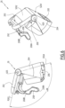
Fig 2 ] lafigure 2 est une vue schématique en perspective d'un actionneur électromécanique du dispositif d'occultation illustré à lafigure 1 ; - [
Fig 3 ] lafigure 3 est une vue schématique en coupe axiale de l'actionneur électromécanique illustré à lafigure 2 , selon le plan III représenté à lafigure 2 ; - [
Fig 4 ] lafigure 4 est une vue schématique en coupe transversale et en perspective de l'actionneur électromécanique illustré auxfigures 2 et3 , selon le plan IV représenté à lafigure 2 ; - [
Fig 5 ] lafigure 5 représente, sur deux inserts A) et B), une vue schématique en coupe transversale de l'actionneur électromécanique illustré auxfigures 2 à 4 , correspondant au détail V à lafigure 4 , l'insert A illustrant une première position d'un volet d'un dispositif de commande de basculement correspondant à un premier mode de fonctionnement d'une unité électronique de contrôle de l'actionneur électromécanique et l'insert B illustrant une deuxième position du volet du dispositif de commande de basculement correspondant à un deuxième mode de fonctionnement de l'unité électronique de contrôle de l'actionneur électromécanique ; - [
Fig 6 ] lafigure 6 représente une vue schématique en perspective du volet appartenant au dispositif de commande de basculement illustré auxfigures 2 à 5 , selon deux angles différents ; - [
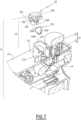
Fig 7 ] lafigure 7 est une vue schématique en coupe partielle et en perspective d'un actionneur électromécanique conforme à un deuxième mode de réalisation, cette coupe étant prise selon un plan comparable au plan VII représenté à lafigure 4 , un volet et un organe mécanique étant représentés en configuration éclatée ; et - [
Fig 8 ] lafigure 8 est un schéma blocs d'un algorithme d'un procédé de commande de l'actionneur électromécanique, tel qu'illustré auxfigures 2 à 7 , conforme à un mode de réalisation de l'invention.
- [
Fig 1 ] therefigure 1 is a schematic perspective view of a concealment device according to a first embodiment of the invention; - [
Fig 2 ] therefigure 2 is a schematic perspective view of an electromechanical actuator of the concealment device illustrated infigure 1 ; - [
Fig.3 ] therepicture 3 is a schematic view in axial section of the electromechanical actuator shown inpicture 2picture 2 - [
Fig 4 ] therefigure 4 is a schematic cross-sectional and perspective view of the electromechanical actuator illustrated infigure 2 And3 , according to plan IV shown infigure 2 ; - [
Fig.5 ] therefigure 5 represents, on two inserts A) and B), a schematic cross-sectional view of the electromechanical actuator illustrated infigures 2 to 4 , corresponding to detail V atfigure 4 , insert A illustrating a first position of a flap of a tilting control device corresponding to a first mode of operation of an electronic control unit of the electromechanical actuator and insert B illustrating a second position of the shutter of the tilting control device corresponding to a second mode of operation of the electronic control unit of the electromechanical actuator; - [
Fig 6 ] therefigure 6 shows a schematic perspective view of the shutter belonging to the tilting control device illustrated infigures 2 to 5 , from two different angles; - [
Fig 7 ] therefigure 7 is a schematic view in partial section and in perspective of an electromechanical actuator according to a second embodiment, this section being taken along a plane comparable to plane VII shown infigure 4 , a flap and a mechanical member being shown in an exploded configuration; And - [
Fig.8 ] therefigure 8 is a block diagram of an algorithm of a method for controlling the electromechanical actuator, as illustrated infigures 2 to 7 , in accordance with one embodiment of the invention.
On décrit tout d'abord, en référence à la
En variante, non représentée, le dispositif d'occultation 1 peut être, notamment, un store plissé, un volet roulant, un portail roulant, une grille ou une porte.Alternatively, not shown, the
Le dispositif d'occultation 1 est, préférentiellement, disposé à l'extérieur du bâtiment.The
En variante, le dispositif d'occultation 1 est disposé à l'intérieur du bâtiment.As a variant, the
Le dispositif d'occultation 1 comprend des lames 3, en particulier orientables. Le dispositif d'occultation 1 comprend, en outre, une barre de charge 4. Ici, l'écran 2 est formé des lames 3 et de la barre de charge 4. La barre de charge 4 permet d'exercer une tension sur l'écran 2.The
En pratique, la barre de charge 4 est fixée au niveau d'une extrémité inférieure de l'écran 2, en particulier dans une configuration assemblée du dispositif d'occultation 1 dans l'installation 100.In practice, the
En variante, non représentée, l'écran 2 comprend une lame finale en remplacement de la barre de charge 4, celle-ci pouvant être lestée.Alternatively, not shown, the
Le dispositif d'occultation 1 comprend des cordons d'entraînement 5 configurés pour permettre un déplacement vertical des lames 3 et de la barre de charge 4. Les cordons d'entraînement 5 peuvent également être appelés des lacettes.The dimming
En pratique, les lames 3 comprennent respectivement des ouvertures, non représentées, de passage de chaque cordon d'entraînement 5.In practice, the blades 3 respectively comprise openings, not shown, for the passage of each
Dans l'exemple de réalisation illustré à la
Avantageusement, dans la configuration assemblée du dispositif d'occultation 1 dans l'installation 100, chaque lame 3 de l'écran 2 repose sur une partie de cordon d'orientation 6, en particulier horizontale et pouvant être appelée barreau, reliant deux brins de cordon d'orientation 6, en particulier verticaux.Advantageously, in the assembled configuration of the
Ainsi, les cordons d'orientation 6 permettent de garantir un espacement vertical régulier des lames 3 de l'écran 2.Thus, the
L'orientation des lames 3 permet, notamment, d'ajuster la luminosité à l'intérieur d'une pièce du bâtiment.The orientation of the slats 3 makes it possible, in particular, to adjust the brightness inside a room of the building.
Lors de la remontée de l'écran 2 et, en particulier, de la barre de charge 4, les lames 3 se superposent sur la barre de charge 4, de sorte à former un empilement.During the ascent of the
Dans un exemple de réalisation, non représenté, le dispositif d'occultation 1 comprend deux coulisses. Chacune des coulisses est disposée le long d'un côté de l'écran 2 du dispositif d'occultation 1. Les coulisses sont configurées pour coopérer avec les lames 3 de l'écran 2, de sorte à guider les lames 3, lors du déploiement et du repli de l'écran 2.In an exemplary embodiment, not shown, the
Dans un autre exemple de réalisation, également non représenté, le guidage des lames 3 est réalisé par deux câbles. Chacun des câbles est disposé le long d'un côté de l'écran 2 du dispositif d'occultation 1.In another exemplary embodiment, also not shown, the guiding of the blades 3 is carried out by two cables. Each of the cables is arranged along one side of the
Le dispositif d'occultation 1 comprend un dispositif d'entraînement motorisé 7.The
Le dispositif d'entraînement motorisé 7 comprend au moins un actionneur électromécanique 8. L'actionneur électromécanique 8 est configuré pour entraîner, autrement dit entraîne, en déplacement l'écran 2. En particulier, l'actionneur électromécanique 8 permet de faire descendre ou monter les lames 3 et la barre de charge 4, autrement dit de déployer ou de replier l'écran 2, selon un mouvement vertical. L'actionneur électromécanique 8 permet, en outre, d'orienter les lames 3.The motorized drive device 7 comprises at least one
Le dispositif d'occultation 1 comprend, en outre, un rail 9, à l'intérieur duquel est disposé le dispositif d'entraînement motorisé 7, notamment l'actionneur électromécanique 8, en particulier dans une configuration assemblée du dispositif d'occultation 1.The
Le rail 9 est disposé, autrement dit est configuré pour être disposé, au-dessus de l'écran 2, en particulier dans la configuration assemblée du dispositif d'occultation 1.The
De manière générale, le rail 9 est disposé au-dessus de l'ouverture du bâtiment, ou encore en partie supérieure de l'ouverture du bâtiment.In general, the
Avantageusement, le rail 9 comprend au moins une paroi de fond 9a et deux parois latérales 9b.Advantageously, the
Dans le mode de montage illustré à la
Avantageusement, le dispositif d'entraînement motorisé 7 comprend, en outre, une pluralité d'enrouleurs. Les enrouleurs sont configurés pour enrouler et dérouler les cordons d'entraînement 5, de sorte à entraîner le déplacement vertical des lames 3 et de la barre de charge 4.Advantageously, the motorized drive device 7 further comprises a plurality of winders. The reels are configured to wind and unwind the
Ici, le dispositif d'entraînement motorisé 7 comprend deux enrouleurs, non visibles sur la
Le nombre d'enrouleurs n'est pas limitatif et peut être différent, en particulier supérieur à deux.The number of winders is not limiting and may be different, in particular greater than two.
Préférentiellement, les enrouleurs sont disposés à l'intérieur du rail 9.Preferably, the reels are arranged inside the
Les cordons d'entraînement 5 sont reliés, d'une part, à la barre de charge 4 et, d'autre part, aux enrouleurs.The
En pratique, dans la configuration assemblée du dispositif d'occultation 1 dans l'installation 100, l'extrémité inférieure de chaque cordon d'entraînement 5 est reliée à la barre de charge 4 et l'extrémité supérieure de chaque cordon d'entraînement 5 est reliée à l'un des enrouleurs.In practice, in the assembled configuration of the
Avantageusement, le dispositif d'entraînement motorisé 7 comprend des dispositifs de basculement 13, généralement dénommés « basculateurs ». Chaque enrouleur est respectivement disposé à l'intérieur d'un basculateur 13. C'est pourquoi les enrouleurs ne sont pas visibles à la
En outre, les basculateurs 13 sont disposés, autrement dit sont configurés pour être disposés, à l'intérieur du rail 9, en particulier dans la configuration assemblée du dispositif d'occultation 1.In addition, the
Dans l'exemple de réalisation illustré à la
Le nombre de basculateurs n'est pas limitatif et peut être différent, en particulier strictement supérieur à deux. Dans le cas où le nombre de basculateurs est supérieur ou égal à deux, l'actionneur électromécanique peut être disposé entre deux des basculateurs.The number of rockers is not limiting and may be different, in particular strictly greater than two. In the case where the number of rockers is greater than or equal to two, the electromechanical actuator can be placed between two of the rockers.
Ici, les basculateurs 13 sont disposés de part et d'autre de l'actionneur électromécanique 8. Préférentiellement, chaque basculateur 13 est disposé au voisinage d'une extrémité du rail 9, suivant la direction longitudinale de celui-ci.Here, the
Les basculateurs 13 sont configurés pour entraîner en rotation, sur une plage de valeur d'angle de rotation limitée, les cordons d'orientation 6, de sorte à orienter les lames 3.The
Le dispositif d'entraînement motorisé 7, en particulier l'actionneur électromécanique 8, est commandé par une unité de commande. Autrement dit, l'unité de commande est configurée pour commander, c'est-à-dire commande, le dispositif d'entraînement motorisé 7, en particulier l'actionneur électromécanique 8.The motor drive device 7, in particular the
L'unité de commande peut être, par exemple, une unité de commande locale 14 ou une unité de commande centrale 15.The control unit can be, for example, a
L'unité de commande locale 14 peut être reliée, en liaison filaire ou non filaire, avec l'unité de commande centrale 15. L'unité de commande centrale 15 peut piloter l'unité de commande locale 14, ainsi que d'autres unités de commande locales similaires et réparties dans le bâtiment.The
Le dispositif d'entraînement motorisé 7 est, de préférence, configuré pour exécuter les commandes de déplacement, notamment de montée ou descente et, éventuellement, d'orientation, de l'écran 2 du dispositif d'occultation 1, pouvant être émises, notamment, par l'unité de commande locale 14 ou l'unité de commande centrale 15.The motorized drive device 7 is preferably configured to execute the displacement commands, in particular for ascent or descent and, possibly, orientation, of the
L'installation 100 et, plus particulièrement, le dispositif d'occultation 1 comprend soit l'unité de commande locale 14, soit l'unité de commande centrale 15, soit l'unité de commande locale 14 et l'unité de commande centrale 15.The
Des moyens de commande de l'actionneur électromécanique 8, permettant le déplacement de l'écran 2 du dispositif d'occultation 1 ainsi que l'orientation des lames 3 de l'écran 2, comprennent au moins une unité électronique de contrôle 19 illustrée aux
Avantageusement, le moteur électrique 18 peut être de type sans balais à commutation électronique, appelé également « BLDC » (acronyme du terme anglo-saxon BrushLess Direct Current) ou « synchrone à aimants permanents », de type asynchrone ou de type à courant continu.Advantageously, the
Avantageusement, l'unité électronique de contrôle 19 est intégrée à l'actionneur électromécanique 8.Advantageously, the
Ainsi, l'unité électronique de contrôle 19 commande, notamment, le moteur électrique 18, de sorte à ouvrir ou fermer l'écran 2, ainsi que de sorte à orienter les lames 3 de l'écran 2, comme décrit précédemment. L'unité électronique de contrôle 19 comprend une carte de circuit imprimé 42, visible aux
En variante, non représentée, l'unité électronique de contrôle 19 peut comprendre plusieurs cartes de circuit imprimé.Alternatively, not shown, the
Avantageusement, l'unité électronique de contrôle 19 comprend au moins un module de communication 49, en particulier de réception d'ordres de commande, les ordres de commande étant émis par un émetteur d'ordres, tel que l'unité de commande locale 14 ou centrale 15, ces ordres étant destinés à commander le dispositif d'entraînement motorisé 7.Advantageously, the
Avantageusement, le module de communication 49 de l'unité électronique de contrôle 19 est de type filaire, autrement dit permet la réception et, éventuellement, l'émission d'ordres de commande transmis par des moyens filaires.Advantageously, the
Avantageusement, l'unité électronique de contrôle 19, l'unité de commande locale 14 et/ou l'unité de commande centrale 15 peuvent être en communication avec une station météorologique, non représentée, disposée à l'intérieur du bâtiment ou déportée à l'extérieur du bâtiment, incluant, notamment, un ou plusieurs capteurs pouvant être configurés pour déterminer, par exemple, une température, une luminosité ou encore une vitesse de vent, dans le cas où la station météorologique est déportée à l'extérieur du bâtiment.Advantageously, the
L'unité électronique de contrôle 19, l'unité de commande locale 14 et/ou l'unité de commande centrale 15 peuvent également être en communication avec un serveur 27, de sorte à contrôler l'actionneur électromécanique 8 suivant des données mises à disposition à distance par l'intermédiaire d'un réseau de communication, en particulier un réseau internet pouvant être relié au serveur 27.The
L'unité électronique de contrôle 19 peut être commandée à partir de l'unité de commande locale 14 ou centrale 15. L'unité de commande locale 14 ou centrale 15 est pourvue d'un clavier de commande. Le clavier de commande de l'unité de commande locale 14 ou centrale 15 comprend un ou plusieurs éléments de sélection 50 et, éventuellement, un ou plusieurs éléments d'affichage 51.The
A titre d'exemples nullement limitatifs, les éléments de sélection peuvent être des boutons poussoirs ou des touches sensitives, les éléments d'affichage peuvent être des diodes électroluminescentes, un afficheur LCD (acronyme du terme anglo-saxon « Liquid Crystal Display ») ou TFT (acronyme du terme anglo-saxon « Thin Film Transistor »). Les éléments de sélection et d'affichage peuvent être également réalisés au moyen d'un écran tactile.By way of non-limiting examples, the selection elements can be push buttons or sensitive keys, the display elements can be light-emitting diodes, an LCD display (acronym of the Anglo-Saxon term "Liquid Crystal Display") or TFT (acronym of the Anglo-Saxon term "Thin Film Transistor"). The selection and display elements can also be produced by means of a touch screen.
Avantageusement, l'unité de commande locale 14 ou centrale 15 comprend au moins un module de communication 48.Advantageously, the local 14 or central 15 control unit comprises at least one
Ainsi, le module de communication 48 de l'unité de commande locale 14 ou centrale 15 est configuré pour émettre, autrement dit émet, des ordres de commande, en particulier par des moyens filaires.Thus, the
En outre, le module de communication 48 de l'unité de commande locale 14 ou centrale 15 peut également être configuré pour recevoir, autrement dit reçoit, des ordres de commande, en particulier par l'intermédiaire des mêmes moyens.Furthermore, the
Le module de communication 48 de l'unité de commande locale 14 ou centrale 15 est appelé par la suite premier module de communication. En outre, le module de communication 49 de l'unité électronique de contrôle 19 est appelé par la suite deuxième module de communication.The
Le premier module de communication 48 de l'unité de commande locale 14 ou centrale 15 est configuré pour communiquer, autrement dit communique, avec le deuxième module de communication 49 de l'unité électronique de contrôle 19.The
Ainsi, le premier module de communication 48 de l'unité de commande locale 14 ou centrale 15 échange des ordres de commande avec le deuxième module de communication 49 de l'unité électronique de contrôle 19, soit de manière monodirectionnelle, soit de manière bidirectionnelle.Thus, the
Avantageusement, l'unité de commande locale 14 est un point de commande, pouvant être fixe ou nomade. Un point de commande fixe peut être un boîtier de commande destiné à être fixé sur une façade d'un mur du bâtiment ou sur une face du cadre dormant d'une fenêtre ou d'une porte. Un point de commande nomade peut être une télécommande, un téléphone intelligent ou une tablette.Advantageously, the
Avantageusement, l'unité de commande locale 14 ou centrale 15 comprend, en outre, un contrôleur 52.Advantageously, the local 14 or central 15 control unit further comprises a
Les moyens de commande de l'actionneur électromécanique 8 comprennent des moyens matériels et/ou logiciels.The control means of the
A titre d'exemple nullement limitatif, les moyens matériels peuvent comprendre au moins un microcontrôleur 29, tel qu'illustré à la
Le dispositif d'entraînement motorisé 7, en particulier l'unité électronique de contrôle 19, est, de préférence, configuré pour exécuter des ordres de commande de déplacement, notamment de déploiement ou de repli de l'écran 2 du dispositif d'occultation 1, ainsi que d'orientation des lames 3. Ces ordres de commande peuvent être émis, notamment, par l'unité de commande locale 14 ou par l'unité de commande centrale 15.The motorized drive device 7, in particular the
Le dispositif d'entraînement motorisé 7 peut être contrôlé par l'utilisateur, par exemple par la réception d'un ordre de commande correspondant à un appui sur le ou l'un des éléments de sélection 50 de l'unité de commande locale 14 ou centrale 15.The motorized drive device 7 can be controlled by the user, for example by receiving a control command corresponding to a press on the or one of the
Le dispositif d'entraînement motorisé 7 peut également être contrôlé automatiquement, par exemple par la réception d'un ordre de commande correspondant à au moins un signal provenant d'au moins un capteur, non représenté, et/ou à un signal provenant d'une horloge, non représentée. Le capteur et/ou l'horloge peuvent être intégrés à l'unité de commande locale 14 ou à l'unité de commande centrale 15.The motorized drive device 7 can also be controlled automatically, for example by receiving a control command corresponding to at least one signal coming from at least one sensor, not shown, and/or to a signal coming from a clock, not shown. The sensor and/or the clock can be integrated in the
Le capteur et/ou l'horloge peuvent également être considérés comme correspondant à une unité de commande, en particulier une unité de commande locale 14.The sensor and/or the clock can also be considered as corresponding to a control unit, in particular a
On décrit à présent, plus en détail et en référence aux
L'actionneur électromécanique 8 comprend, entre autres, le moteur électrique 18 et l'unité électronique de contrôle 19.The
Ici, le moteur électrique 18 comprend un stator 182, un rotor 184 et un arbre de rotation 186. L'arbre de rotation 186 est solidaire du rotor 184. L'arbre de rotation 186 est configuré pour être entraîné en rotation, autrement dit est entraîné en rotation, autour d'un axe de rotation X. Ici, l'arbre de rotation 186 dépasse aux deux extrémités opposées de l'actionneur électromécanique 8 et constitue un arbre de sortie pour cet actionneur électromécanique 8.Here, the
En variante, non représentée, l'arbre de rotation 186 est limité axialement à la longueur du moteur électrique 18 et connecté à deux arbres de sortie de l'actionneur électromécanique 8 qui dépassent respectivement à chacune des extrémités de celui-ci, voire à un arbre de sortie qui ne dépasse qu'à une seule extrémité de celui-ci.Alternatively, not shown, the
Ici, le stator 182 et le rotor 184 sont positionnés de manière coaxiale autour de l'axe de rotation X. En outre, l'arbre de rotation 186 est intégré ou accouplé au rotor 184.Here, the
L'axe de rotation X est également l'axe de rotation des enrouleurs, dans une configuration montée du dispositif d'entraînement motorisé 7.The axis of rotation X is also the axis of rotation of the reels, in a mounted configuration of the motor drive device 7.
L'actionneur électromécanique 8 permet de déplacer l'écran 2 du dispositif d'occultation 1, en particulier selon un mouvement vertical, ainsi que d'orienter les lames de l'écran 2.The
Avantageusement, l'actionneur électromécanique 8 comprend, en outre, un câble d'alimentation électrique 10.Advantageously, the
L'actionneur électromécanique 8 est configuré pour être alimenté, autrement dit est alimenté, en énergie électrique par une source d'alimentation électrique principale 54, par l'intermédiaire du câble d'alimentation électrique 10.The
Avantageusement, la source d'alimentation électrique principale 54 peut être un réseau d'alimentation électrique du secteur ou une batterie, pouvant être rechargée, par exemple, par un panneau photovoltaïque ou un chargeur, non représenté.Advantageously, the main
L'actionneur électromécanique 8 comprend, en outre, un carter 17, en particulier tubulaire.The
Le moteur électrique 18 et l'unité électronique de contrôle 19 sont logés, autrement dit montés, à l'intérieur du carter 17, en particulier dans une configuration assemblée de l'actionneur électromécanique 8.The
Ici, le carter 17 de l'actionneur électromécanique 8 comprend une pluralité de tronçons, dont au moins trois tronçons désignés par les références 17A, 17B, 17C. Il est de forme parallélépipédique et, plus particulièrement, présente une section de forme globalement rectangulaire.Here, the
En variante, non représentée, le carter 17 de l'actionneur électromécanique 8 est de forme cylindrique à section circulaire.Alternatively, not shown, the
Avantageusement, l'actionneur électromécanique 8 comprend, en outre, au moins un réducteur 12.Advantageously, the
Le réducteur 12 comprend au moins un étage de réduction. L'étage de réduction peut être un train d'engrenages de type épicycloïdal.The
Le type et le nombre d'étages de réduction du réducteur ne sont pas limitatifs. Les étages de réduction peuvent être, par exemple, au nombre de deux ou trois.The type and number of reduction stages of the reducer are not limiting. The reduction stages can be, for example, two or three in number.
Chaque extrémité de l'arbre de rotation 186 porte une douille 187 d'accouplement à un arbre d'entraînement 11 de l'un des enrouleurs.Each end of the
Chaque enrouleur est ainsi entraîné en rotation, au niveau de l'un des basculateurs 13, par l'un des arbres d'entraînement 11 couplé avec l'arbre de sortie 186 de l'actionneur électromécanique 8.Each winder is thus driven in rotation, at one of the
Avantageusement, l'actionneur électromécanique 8 comprend, en outre, un frein 46, comme illustré à la
A titre d'exemples nullement limitatifs, le frein 46 peut être un frein à ressort, un frein à came, un frein magnétique ou un frein électromagnétique.By way of non-limiting examples, the
Ici, le réducteur 12 et le frein 46 sont également logés dans le carter 17 de l'actionneur électromécanique 8.Here, the
En variante, non représentée, le réducteur 12 et le frein 46 sont disposés à l'extérieur du carter 17 de l'actionneur électromécanique 8.Alternatively, not shown, the
Avantageusement, l'actionneur électromécanique 8 comprend, en outre, un dispositif de détection de fin de course 21.Advantageously, the
L'écran 2 comprend la pluralité de lames 3, dont une première lame 3h. La première lame 3h fait face à la paroi de fond 9a du rail 9, en particulier dans la configuration assemblée du dispositif d'occultation 1. Autrement dit, la première lame 3h de l'écran 2 correspond à la lame 3 supérieure de l'écran 2.The
Dans le cas d'un store à lames, une position haute, en particulier de sécurité, correspond à une mise en appui de la première lame 3h de l'écran 2 contre un élément du dispositif de détection de fin de course 21.In the case of a slatted blind, a high position, in particular a safety position, corresponds to pressing the
Le dispositif de détection de fin de course 21 permet, notamment, de déterminer l'atteinte de la position de fin de course haute de l'écran 2.The end-of-
Le dispositif de détection de fin de course 21 est généralement appelé « champignon ».The end-of-
Une position de fin de course haute, en particulier de fonctionnement, correspond à une position de fin de course haute prédéterminée, en particulier programmée au moyen de l'unité électronique de contrôle 19 et déterminée au moyen d'un dispositif de comptage 35.A high limit position, in particular for operation, corresponds to a predetermined high limit position, in particular programmed by means of the
En outre, une position de fin de course basse correspond à une position de fin de course basse prédéterminée, en particulier programmée au moyen de l'unité électronique de contrôle 19 et déterminée au moyen du dispositif de comptage 35, ou à la mise en appui de la barre de charge 4 contre un seuil de l'ouverture du bâtiment, ou encore au déploiement complet de l'écran 2.In addition, a bottom end-of-travel position corresponds to a predetermined bottom end-of-travel position, in particular programmed by means of the
Ici, le dispositif de comptage 35 peut être de type magnétique. Un tel dispositif de comptage 35 comprend au moins une roue, pouvant être assemblée sur l'arbre de rotation 186 du moteur électrique 18, et des capteurs à effet Hall, qui ne sont pas représentés en détail.Here, the
Par ailleurs, le type de dispositif de comptage 35 n'est pas limitatif et peut être différent, en particulier de type optique ou de type temporel et réalisé au travers du microcontrôleur 29 de l'unité électronique de contrôle 19.Furthermore, the type of
Avantageusement, le dispositif de détection de fin de course 21 comprend un organe 22, mobile à l'intérieur d'un boîtier 17D formé par une partie du carter 17, dans l'exemple monobloc avec la partie 17A du carter 17, et, éventuellement, un organe de rappel élastique 23 formé par un ressort hélicoïdal.Advantageously, the end-of-
En variante, non représentée, le boîtier 17D du dispositif de détection de fin de course 21 peut être formé par une partie du carter 17 rapportée sur la partie 17A du carter 17 et fixée sur celle-ci, par exemple au moyen d'éléments de fixation par vissage ou par encliquetage élastique.As a variant, not shown, the
Ici, le boîtier 17D du dispositif de détection de fin de course 21 est cylindrique et présente une section intérieure de forme globalement circulaire.Here, the
En variante, non représentée, le boîtier 17D du dispositif de détection de fin de course 21 est de forme parallélépipédique.Alternatively, not shown, the
En variante, non représentée, l'organe de rappel élastique 23 peut être différent d'un ressort hélicoïdal, par exemple un bloc de matériau élastiquement déformable.Alternatively, not shown, the
L'organe 22 est mobile en translation selon un axe A22 radial à l'axe de rotation X. L'organe 22 est pourvu d'une tige rectiligne 22A qui est engagée dans un tube creux 17E, formé par une partie du carter 17 et qui est centré sur l'axe A22. Le mouvement de translation de l'organe 22 selon l'axe A22 est guidé par la coopération de formes des parties 17E et 22A.The
L'organe 22 comprend une tête 22B en saillie du boîtier 17D et destinée à recevoir en appui la première lame 3h, lorsque l'écran 2 parvient dans sa position de fin de course haute. Pour ce faire, le boîtier 17D et l'organe 22 sont engagés par le dessus dans une lumière, non représentée, ménagée dans la paroi de fond 9a du rail 9. Lorsqu'il est repoussé par la première lame 3h le long de l'axe A22, l'organe 22 actionne un interrupteur 43 porté par la carte de circuit imprimé 42. Ceci permet à l'unité électronique de contrôle 19 de détecter que l'écran 2 est en position de fin de course haute.The
Dans un exemple de réalisation, le carter 17 est réalisé au moins en partie dans un matériau métallique.In an exemplary embodiment, the
La matière du carter de l'actionneur électromécanique n'est pas limitative et peut être différente. Il peut, en particulier, s'agir d'une matière plastique.The material of the housing of the electromechanical actuator is not limiting and can be different. It may, in particular, be a plastic material.
L'unité électronique de contrôle 19 est configurée pour commander, autrement dit commande, le moteur électrique 18 dans un premier mode de fonctionnement, dit de commande, normal ou d'usage, où elle alimente en énergie électrique le moteur électrique 18 en fonction des mouvements de montée ou de descente de l'écran 2, ainsi que des mouvements d'orientation des lames 3 de l'écran 2.The
L'unité électronique de contrôle 19 est également configurée pour commander, autrement dit commande, le moteur électrique 18 dans un deuxième mode de fonctionnement, en particulier d'apprentissage, de configuration, de programmation ou de réglage, qui met en œuvre le dispositif de comptage 35 pour déterminer et mémoriser une ou plusieurs positions de fin de course de l'écran 2.The
Lors de la mise en service du dispositif d'occultation 1 et au cours de sa durée d'utilisation, il est nécessaire de faire basculer l'unité électronique de contrôle 19 entre les premier et deuxième modes de fonctionnement.During the commissioning of the
L'actionneur électromécanique 8 comprend, en outre, un dispositif de commande de basculement 25. Le dispositif de commande de basculement 25 est configuré pour basculer, autrement dit bascule, l'unité électronique de contrôle 19 entre les premier et deuxième modes de fonctionnement.The
Le dispositif de commande de basculement 25 est basé sur une technologie de détection magnétique, plus fiable que les dispositifs de commande de basculement purement mécaniques de l'art antérieur, qui permet de savoir précisément quand l'unité électronique de contrôle 19 doit basculer entre les premier et deuxième modes de fonctionnement.The tilting
Avantageusement, le long d'un axe A17, illustré à la
Ainsi, le dispositif de commande de basculement 25 peut être inséré dans la même lumière ménagée dans la paroi de fond 9a du rail 9 que celle du dispositif de détection de fin de course 21 ou dans une lumière adjacente ménagée dans la paroi de fond 9a du rail 9 à celle du dispositif de détection de fin de course 21, tout en étant accessible par le dessous de ce rail 9.Thus, the tilting
A cet égard, le dispositif de commande de basculement 25 est positionné d'une façon comparable aux dispositifs purement mécaniques de l'art antérieur, de sorte que son incorporation dans le dispositif d'occultation 1 conforme à l'invention ne change pas fondamentalement les habitudes de travail d'un opérateur habitué aux matériels déjà présents sur le marché et comprenant un dispositif de commande de basculement purement mécanique.In this respect, the tilting
Le dispositif de commande de basculement 25 comprend un volet 26, visible en perspective sous deux angles différents à la
En variante, non représentée, le boîtier 17F du dispositif de commande de basculement 25 peut être formé par une partie du carter 17 rapportée sur la partie 17A du carter 17 et fixée sur celle-ci, par exemple au moyen d'éléments de fixation par vissage ou par encliquetage élastique.Alternatively, not shown, the
Le boîtier 17F peut également être appelé premier boîtier et le boîtier 17D peut également être appelé deuxième boîtier.
Avantageusement, l'axe A25 d'articulation du volet 26 par rapport au boîtier 17F est parallèle à l'axe de rotation X, en particulier dans la configuration assemblée de l'actionneur électromécanique 8.Advantageously, axis A25 of articulation of
En variante, non représentée, l'axe A25 peut être orienté différemment, notamment être perpendiculaire à l'axe de rotation X.Alternatively, not shown, the axis A25 can be oriented differently, in particular be perpendicular to the axis of rotation X.
Avantageusement, le volet 26 est réalisé dans un matériau amagnétique.Advantageously, the
Avantageusement, le volet 26 comprend un premier panneau 262 et un deuxième panneau 264.Advantageously, the
Ici, les premier et deuxième panneaux 262, 264 s'étendent chacun selon un plan P262, P264.Here, the first and
Les plans P262, P264 définissent entre eux un angle α26 autour d'un axe A26 du volet 26 qui est confondu avec l'axe A25 en configuration montée du volet 26 dans le boîtier 17F.The planes P262, P264 define between them an angle α26 around an axis A26 of the
On note B17 un bord, dit « libre », du boîtier 17F, opposé à la partie 17A du carter 17. Ce bord B17 délimite une ouverture d'accès au volume interne du boîtier 17F, dans lequel est logé le volet 26.Note B17 an edge, called "free", of the
Ici, ce bord B17 a une forme globalement rectangulaire, avec des coins arrondis, ce qui correspond à la section du boîtier 17F dans sa partie la plus éloignée de la partie 17A du carter 17. Dans l'exemple des figures, l'axe A25 est parallèle aux petits côtés du bord B17 et est disposé à égale distance de ces petits côtés.Here, this edge B17 has a generally rectangular shape, with rounded corners, which corresponds to the section of the
Comme le montre la
Avantageusement, une surface externe S264 du deuxième panneau 264 du volet 26 est affleurante avec le bord B17 dans une première position, dite extrême, du volet 26 représentée aux
Le volet 26 peut prendre toutes les positions intermédiaires entre la première position et la deuxième position, en tournant autour de l'axe A25.The
Le passage de la première position du volet 26 représentée sur l'insert A) à la deuxième position représentée sur l'insert B) a lieu par basculement du volet 26 autour des axes A25 et A26 confondus, sur un secteur angulaire dont on note β26 l'angle au sommet.The passage from the first position of the
Ici et de manière nullement limitative, la somme des angles α26 et β26 est égale à 180°.Here and in no way limiting, the sum of the angles α26 and β26 is equal to 180°.
Avantageusement, le premier panneau 262 est pourvu, sur sa surface externe S262, d'un premier logement en creux 263.Advantageously, the
Ainsi, ce premier logement en creux 263 permet de recevoir la pointe d'un outil, tel qu'un tournevis, lorsqu'un opérateur exerce sur le premier panneau 262 un effort de pivotement autour des axes A25, A26, comme représenté par la flèche F1 sur l'insert B) de la
De la même façon, le deuxième panneau 264 est pourvu, sur sa surface externe S264, d'un deuxième logement en creux 265.In the same way, the
Ainsi, ce deuxième logement en creux 265 permet de recevoir l'extrémité d'un outil, tel qu'un tournevis, lorsqu'un opérateur exerce sur le deuxième panneau 264 un effort de pivotement autour des axes A25, A26, comme représenté par la flèche F2 sur l'insert A) de la
En variante, non représentée, les premier et deuxième panneaux 262, 264 sont dépourvus de premier et deuxième logements en creux 263, 265.Alternatively, not shown, the first and
Avantageusement, le volet 26, en particulier le deuxième panneau 264, comprend un logement 266, dans lequel est disposé un aimant permanent 27, qui appartient au dispositif de commande de basculement 25.Advantageously, the
Ici, l'aimant permanent 27 est complètement reçu dans le logement 266.Here, the
En variante, non représentée, une partie de l'aimant permanent 27 peut être en saillie du logement 266.Alternatively, not shown, part of the
D'autre part, le dispositif de commande de basculement 25 comprend un capteur magnétique 28, en particulier à effet Hall. Ce capteur magnétique 28 est monté à l'intérieur du carter 17, à proximité du boîtier 17F, plus précisément à proximité d'une surface intérieure de ce boîtier 17F. Ce capteur magnétique 28 est supporté par la carte de circuit imprimé 42, ou par un autre support, qui appartient également à l'unité de contrôle électronique 19.On the other hand, the tilting
Lorsque le volet 26 passe de sa première position à sa deuxième position, ou inversement, le déplacement de l'aimant permanent 27 induit par le pivotement du volet 26, en particulier du deuxième panneau 264, autour de l'axe A25 est détecté par le capteur magnétique 28.When the
Ainsi, le capteur magnétique 28 est en mesure de signaler au microcontrôleur 29 que le dispositif de commande de basculement 25 a été actionné, du fait de l'application de l'un des efforts représentés par les flèches F1, F2.Thus, the
La forme intérieure du boîtier 17F est compatible avec le pivotement du volet 26, en particulier du deuxième panneau 264, entre ses première et deuxième positions représentées sur les deux inserts A, B de la
A cet effet, la surface intérieure du boîtier 17F comprend un tronçon 172 en forme de cylindre à section circulaire centré sur l'axe A25 et dont le rayon est supérieur ou égal à la plus grande dimension du deuxième panneau 264 mesuré radialement à l'axe A26.For this purpose, the inner surface of the
Le volet 26 comprend au moins une patte de retenue en position 268 du volet 26.The
Ici, le volet 26, en particulier le premier panneau 262, comprend une seule patte de retenue en position 268.Here, the
Avantageusement, le boîtier 17F comprend une première butée et une deuxième butée. La première butée est configurée pour coopérer, autrement dit coopère, avec la patte de retenue en position 268, lorsque le volet 26 est dans la première position. En outre, la deuxième butée est configurée pour coopérer, autrement dit coopère, avec la patte de retenue en position 268, lorsque le volet 26 est dans la deuxième position.Advantageously, the
Ici, le boîtier 17F, en particulier sa surface intérieure, comprend, d'une part, une encoche 174 définissant la première butée du boîtier 17F et, d'autre part, un coin rentrant 176 et un renfoncement 178 définissant la deuxième butée du boîtier 17F.Here, the
Ainsi, la patte de retenue en position 268 est configurée pour coopérer, autrement dit coopère, avec l'encoche 174 dans la première position du volet 26 et avec le coin rentrant 176 et le renfoncement 178 dans la deuxième position de ce volet 26.Thus, the retaining tab in
Ici, la patte de retenue en position 268 est élastiquement déformable.Here, the retaining tab in
Ici, la patte de retenue en position 268 comprend une extrémité libre 268A.Here,
D'une part, dans la première position du volet 26, l'extrémité libre 268A de la patte de retenue en position 268 est engagée dans l'encoche 174.On the one hand, in the first position of the
En outre, au moyen d'une déformation élastique de la patte de retenue en position 268, qui est alors en appui contre un bord de l'encoche 174, son extrémité libre 268A peut être extraite de l'encoche 174.In addition, by means of an elastic deformation of the retaining tab in
Dans ces conditions, lorsque le volet 26 est dans sa première position représentée à l'insert A) de la
Ainsi, la position représentée sur l'insert A de la
De cette manière, l'aimant permanent 27 ne risque pas d'être déplacé de façon accidentelle autour de l'axe A25. Aucun mouvement parasite de l'aimant permanent 27 autour de l'axe A25 ne risque donc d'être détecté par le capteur magnétique 28.In this way, the
Ici, la patte de retenue en position 268 comprend, en outre, un bourrelet 268B.Here, the retaining tab in
D'autre part, dans la deuxième position du volet 26, l'extrémité libre 268A de la patte de retenue en position 268 est engagée dans le coin rentrant 176 et le bourrelet 268B de la patte de retenue en position 268 est engagé dans le renfoncement 178.On the other hand, in the second position of the
En outre, au moyen d'une déformation élastique de la patte de retenue en position 268, qui est alors en appui contre un bord du renfoncement 178, le bourrelet 268B peut sortir du renfoncement 178.In addition, by means of an elastic deformation of the retaining tab in
Dans ces conditions, lorsque le volet 26 est dans sa deuxième position représentée à l'insert B) de la
Ainsi, la position représentée sur l'insert B) de la
De cette manière, l'aimant permanent 27 ne risque pas d'être déplacé de façon accidentelle autour de l'axe A25. Aucun mouvement parasite de l'aimant permanent 27 autour de l'axe A25 ne risque donc d'être détecté par le capteur magnétique 28.In this way, the
Par conséquent, le volet 26 peut être qualifié de « bistable », car les deux positions représentées sur les inserts A) et B) de la
Compte tenu du caractère bistable du volet 26, aucune fausse détection d'une activation du dispositif de commande de basculement 25 par l'opérateur ne risque de se produire.Given the bistable nature of the
Avantageusement, c'est la même patte de retenue en position 268 qui est susceptible de venir en appui contre la surface interne du boîtier 17F dans les première et deuxième positions du volet 26.Advantageously, it is the same retaining lug in
Ceci est avantageux en termes de fabrication et d'inertie du volet 26.This is advantageous in terms of manufacture and inertia of the
En variante, non représentée, le volet 26, comprend une pluralité de pattes de retenue en position 268.Alternatively, not shown, the
Dans un tel cas, le volet 26 peut être équipé d'une première patte de retenue en position 268, configurée pour prendre appui, autrement dit prenant appui, sur le boîtier 17F, lorsque celui-ci est dans sa première position et d'une deuxième patte de retenue en position 268, configurée pour prendre appui, autrement dit prenant appui, sur le boîtier 17F, lorsqu'il est dans sa deuxième position, la deuxième patte de retenue en position 268 étant différente de la première patte de retenue en position 268. La première patte de retenue en position 268 est configurée pour coopérer, autrement dit coopère, avec l'encoche 174. En outre, la deuxième patte de retenue en position 268 est configurée pour coopérer, autrement dit coopère, avec le renfoncement 178. Ces deux pattes de retenue en position 268 rendent alors stables, à elles deux, les deux positions du volet 26 en venant en appui respectivement contre une première butée et contre une deuxième butée, comparables aux reliefs internes concaves 174, 176, 178.In such a case, the
La position de l'aimant permanent 27 peut être repérée par le capteur magnétique 28, par exemple en détectant la distance et/ou l'orientation relative(s) du pôle Sud ou du pôle Nord de l'aimant permanent 27 par rapport au capteur magnétique 28. Cette position de l'aimant permanent 27 détectée par le capteur magnétique 28 peut être stockée dans une mémoire 47, en particulier non volatile, de l'unité électronique de contrôle 19, en particulier du microcontrôleur 29, sous la forme d'un paramètre représentatif de cette position. Ce paramètre peut être binaire, par exemple égal à 0 ou 1, pour représenter soit la position de l'insert A) soit la position de l'insert B) de la
Dans le deuxième mode de réalisation, illustré partiellement à la
Dans le deuxième mode de réalisation, l'actionneur électromécanique 8 comprend, en outre, un organe mécanique 126. L'organe mécanique 26 est configuré pour délivrer, autrement dit délivre, une information sonore, lorsque le volet 26 pivote entre sa première position et sa deuxième position, et/ou inversement.In the second embodiment, the
Avantageusement, l'organe mécanique 126 est un élément de rappel élastique, en particulier un ressort.Advantageously, the
Avantageusement, l'organe mécanique 126 est interposé entre le volet 26, qui est comparable au volet 26 du premier mode de réalisation, et une partie 17F1, en particulier le fond, du boîtier 17F.Advantageously, the
Ici, le volet 26 et le boîtier 17F appartiennent au dispositif de commande de basculement 25.Here, the
Ainsi, l'organe mécanique 126 est logé, autrement dit est configuré pour être logé, à l'intérieur du boîtier 17F, en particulier dans la configuration assemblée de l'actionneur électromécanique 8.Thus, the
Avantageusement, le volet 26 comprend, en outre, deux pattes de maintien 269. En outre, l'organe mécanique 126 est monté, autrement dit est configuré pour être monté, sur les deux pattes de maintien 269 du volet 26, en particulier dans la configuration assemblée de l'actionneur électromécanique 8.Advantageously, the
Avantageusement, l'organe mécanique 126 vient en appui, autrement dit est configuré pour venir en appui, contre la partie 17F1 du boîtier 17F, lorsque le volet 26 pivote entre sa première position et sa deuxième position, et/ou inversement.Advantageously, the
Ainsi, lors du basculement du volet 26 entre ses première et deuxièmes positions, ou inversement, définies comme dans le premier mode de réalisation, l'organe mécanique 126 est comprimé et puis se détend brusquement en faisant un bruit de « clic » qui est perçu par l'utilisateur.Thus, when tilting the
De cette manière, l'utilisateur est informé par l'information sonore délivrée par l'organe mécanique 126 que le volet 26 a effectivement changé de position, de sa première position vers sa deuxième position, ou inversement.In this way, the user is informed by the sound information delivered by the
L'organe mécanique 126 peut délivrer une telle information lorsque le volet 26 pivote de sa première position vers sa deuxième position, de sa deuxième position vers sa première position ou dans les deux cas.The
Avantageusement, l'organe mécanique 126 est métallique, par exemple réalisé en acier.Advantageously, the
En variante, l'organe mécanique 126 peut être réalisé dans un autre matériau, notamment composite.Alternatively, the
Ici et comme illustré à la
En variante, non représentée, l'organe mécanique 126 peut avoir une forme différente ou être remplacé par un autre organe mécanique, tel que, par exemple, une agrafe ou une languette, capable de délivrer une information sonore à l'utilisateur lorsque le volet 26 pivote entre ses première et deuxième positions, ou inversement.Alternatively, not shown, the
On décrit à présent, en référence à la
Ce procédé est mis en œuvre au moyen de l'unité électronique de contrôle 19 et, en particulier, du microcontrôleur 29.This method is implemented by means of the
Avantageusement, le procédé comprend, initialement, une première étape 1001 de mise sous tension de l'actionneur électromécanique 8.Advantageously, the method includes, initially, a
Une première valeur V1 du paramètre représentatif de la position de l'aimant permanent 27 détectée par le capteur magnétique 28 a été stockée dans la mémoire 47 de l'unité électronique de contrôle 19.A first value V1 of the parameter representative of the position of the
Cette mémorisation de la première valeur V1 a pu être mise en œuvre, notamment, lors de la dernière mise sous tension précédente de l'actionneur électromécanique 8.This storage of the first value V1 could be implemented, in particular, during the last previous power-up of the
Cette première valeur V1 est mémorisée dans la mémoire 47, y compris lors d'un arrêt de l'alimentation en énergie électrique de l'actionneur électromécanique 8.This first value V1 is stored in
Le procédé comprend une deuxième étape 1002 de lecture de la première valeur V1, dans la mémoire 47 de l'unité électronique de contrôle 19.The method comprises a
Avantageusement, la deuxième étape 1002 de lecture peut être mise en œuvre suite à la première étape 1001 de mise sous tension de l'actionneur électromécanique 8.Advantageously, the
Dans ce cas, la mémorisation de la première valeur V1 est mise en œuvre lors d'une étape de mise sous tension de l'actionneur électromécanique 8 antérieure à la présente étape de mise sous tension 1001.In this case, the storage of the first value V1 is implemented during a step of powering up the
Le procédé comprend une troisième étape 1003 de détection de la position de l'aimant permanent 27 par le capteur magnétique 28. Une deuxième valeur V2 du même paramètre que celui de la première valeur V1 est déterminée lors de cette troisième étape 1003 de détection. Puis, cette deuxième valeur V2 est stockée dans la mémoire 47 de l'unité électronique de contrôle 19.The method comprises a
Avantageusement, la troisième étape 1003 de détection peut être mise en œuvre suite à la première étape 1001 de mise sous tension de l'actionneur électromécanique 8.Advantageously, the
L'ordre des deuxième et troisième étapes 1002, 1003 peut être inversé ou celles-ci peuvent être exécutées simultanément.The order of the second and
Le procédé comprend une quatrième étape 1004 de comparaison de la première valeur V1, lue lors de la deuxième étape 1002 de lecture, avec la deuxième valeur V2, déterminée lors de la troisième étape 1003 de détection.The method comprises a
Le procédé comprend une première étape 1005 de mise en fonctionnement de l'unité électronique de contrôle 19 dans le premier mode de fonctionnement et une deuxième étape 1006 de mise en fonctionnement de l'unité électronique de contrôle 19 dans le deuxième mode de fonctionnement.The method comprises a
Si, lors de la quatrième étape 1004 de comparaison, la première valeur V1, lue à la deuxième étape 1002 de lecture, est déterminée comme étant identique à la deuxième valeur V2, déterminée à la troisième étape 1003 de détection, alors le procédé met en œuvre la première étape 1005 de mise en fonctionnement de l'unité électronique de contrôle 19 dans le premier mode de fonctionnement.If, during the
Ainsi, si le résultat de cette comparaison est que la deuxième valeur V2 est égale à la première valeur V1, c'est-à-dire que la deuxième valeur V2 du paramètre détecté par le capteur magnétique 28 n'a pas changé depuis la dernière mise sous tension précédente de l'actionneur électromécanique 8, alors le dispositif de commande de basculement 25 n'a pas été actionné. Dans ce cas, la première étape 1005 de mise en fonctionnement, autrement dit de commande, de l'actionneur électromécanique 8 est exécutée.Thus, if the result of this comparison is that the second value V2 is equal to the first value V1, that is to say that the second value V2 of the parameter detected by the
Si, lors de la quatrième étape 1004 de comparaison, la première valeur V1, lue à la deuxième étape 1002 de lecture, est déterminée comme étant différente de la deuxième valeur V2, déterminée à la troisième étape 1003 de détection, alors le procédé met en œuvre la deuxième étape 1006 de mise en fonctionnement de l'unité électronique de contrôle 19 dans le deuxième mode de fonctionnement.If, during the
Ainsi, si la deuxième valeur V2 diffère de la première valeur V1, c'est-à-dire que la deuxième valeur V2 du paramètre détecté par le capteur magnétique 28 a changé depuis la dernière mise sous tension précédente de l'actionneur électromécanique 8, alors le dispositif de commande de basculement 25 a été actionné, en passant de l'une des positions représentées à la
De cette manière, l'actionneur électromécanique 8 peut être piloté dans le deuxième mode de fonctionnement par l'unité électronique de contrôle 19, en particulier dans un mode de fonctionnement permettant de régler l'une au moins des positions de fin de course.In this way, the
Grâce à la présente invention, quel que soit le mode de réalisation, le dispositif de commande de basculement peut être facilement intégré à l'actionneur électromécanique. La patte de retenue en position du volet par rapport au boîtier garantit un fonctionnement bistable du dispositif de commande de basculement.Thanks to the present invention, whatever the embodiment, the tilting control device can be easily integrated into the electromechanical actuator. The retaining lug in the position of the shutter relative to the housing guarantees bistable operation of the tilting control device.
De cette manière, le dispositif de commande de basculement permet de piloter de façon fiable le basculement de l'unité électronique de contrôle entre au moins ses deux modes de fonctionnement.In this way, the tilting control device makes it possible to reliably control the tilting of the electronic control unit between at least its two operating modes.
En outre, le fait de monter l'aimant permanent sur le volet permet de réaliser le dispositif de commande de basculement sous une forme compacte et garantit une détection fiable de son activation par un opérateur.In addition, the fact of mounting the permanent magnet on the flap makes it possible to produce the tilting control device in a compact form and guarantees reliable detection of its activation by an operator.
De nombreuses modifications peuvent être apportées aux exemples de réalisation décrits précédemment, sans sortir du cadre de l'invention défini par les revendications.Many modifications can be made to the embodiments described above, without departing from the scope of the invention defined by the claims.
Dans un autre exemple de réalisation, non représenté, le dispositif d'entraînement motorisé 7 comprend, outre une pluralité de premiers enrouleurs des cordons d'entraînement 5, une pluralité de deuxièmes enrouleurs des cordons d'orientation 6. Dans ce cas, les cordons d'entraînement 5 sont reliés, d'une part, à la barre de charge 4 et, d'autre part, aux premiers enrouleurs. Les cordons d'orientation 6 sont reliés, d'une part, à la barre de charge 4 et aux lames 3 et, d'autre part, aux deuxièmes enrouleurs. En pratique, l'extrémité inférieure de chaque cordon d'entraînement 5 est reliée à la barre de charge 4 et l'extrémité supérieure de chaque cordon d'entraînement 5 est reliée à l'un des premiers enrouleurs, en particulier dans la configuration assemblée du dispositif d'occultation 1 dans l'installation 100. L'extrémité inférieure de chaque cordon d'orientation 6 est reliée à la barre de charge 4 et l'extrémité supérieure de chaque cordon d'orientation 6 est reliée à l'un des deuxièmes enrouleurs, en particulier dans la configuration assemblée du dispositif d'occultation 1 dans l'installation 100. Préférentiellement, les premiers et deuxièmes enrouleurs sont disposés à l'intérieur du rail 9.In another exemplary embodiment, not shown, the motorized drive device 7 comprises, in addition to a plurality of first reels of the
Dans un autre exemple de réalisation, non représenté, le dispositif d'entraînement motorisé 7 comprend deux chaînes d'entraînement et d'orientation des lames 3 de l'écran 2, en remplacement des cordons d'entraînement 5 et des cordons d'orientation 6. Dans un tel cas, chaque chaîne est disposée à l'intérieur de l'une des coulisses, disposée le long d'un côté de l'écran 2 du dispositif d'occultation 1.In another exemplary embodiment, not shown, the motorized drive device 7 comprises two chains for driving and orienting the slats 3 of the
En variante, le deuxième module de communication 49 de l'unité électronique de contrôle 19 est configuré pour recevoir, autrement dit reçoit, et, éventuellement, pour émettre, autrement dit émet, des ordres de commande transmis par des moyens sans fil, en particulier, des ordres de commande radioélectriques. En outre, le premier module de communication 48 de l'unité de commande locale 14 ou centrale 15 est configuré pour émettre, autrement dit émet, et, éventuellement, pour recevoir, autrement dit reçoit, des ordres de commande, en particulier par des moyens sans fil, par exemple radioélectriques.As a variant, the
En variante, le capteur magnétique 28 peut être différent d'un capteur à effet Hall. Il peut s'agir d'un capteur inductif ou d'un capteur magnéto-résistif, pouvant être basé, par exemple, sur une technologie dite « GMR » (acronyme de l'expression anglo-saxonne « Giant Magnéto Résistance »).As a variant, the
Sur les inserts A) et B) de la
En variante, le dispositif de commande de basculement 25 peut être configuré pour basculer l'unité électronique de contrôle 19 dans un autre mode de fonctionnement. Cet autre mode de fonctionnement de l'unité électronique de contrôle 19 peut être en complément ou en remplacement du deuxième de fonctionnement, dit de « paramétrage » d'une ou plusieurs positions de fin de course de l'écran 2.As a variant, the switching
A titre d'exemples nullement limitatifs, l'unité électronique de contrôle 19 peut être basculée :
- dans un troisième mode de fonctionnement, où la ou les positions de fin de course de l'écran 2 sont réinitialisées. L'entrée dans ce troisième mode de fonctionnement peut être mise en œuvre, notamment, en exécutant une séquence prédéterminée de commutations du volet 26 entre ses première et deuxième positions, et/ou
- dans un quatrième mode de fonctionnement,
où l'écran 2 est entraîné en déplacement jusqu'à la position de fin de course haute, dite de sécurité, autrement dit à une mise en appui de la première lame 3h de l'écran 2contre l'organe 22 du dispositif de détection de fin decourse 21. L'entrée dans ce quatrième mode de fonctionnement peut être mise en œuvre, notamment, par une séquence prédéterminée de commutations du volet 26 entre ses première et deuxième positions, et/ou - dans un cinquième mode de fonctionnement, où un niveau de sensibilité d'une détection d'obstacle, lors de l'entraînement en déplacement de l'écran 2
par l'actionneur électromécanique 8, est réglé, voire la désactivation de la détection d'obstacle. L'entrée dans ce cinquième mode de fonctionnement peut être mise en œuvre, par exemple, par une séquence prédéterminée de commutations du volet 26 entre ses première et deuxième positions. La détection d'obstacle peut être mise en œuvre par l'unité électronique de contrôle 19, de manière temporelle, au moyen du microcontrôleur 29, et/ou au travers du dispositif de comptage 35, et/ou par une mesure d'un paramètre de fonctionnement du moteur électrique 18, telle qu'une mesure de courant traversant le moteur électrique 18 au moyen d'une résistance de shunt.
- in a third mode of operation, where the limit position(s) of the
screen 2 are reinitialized. Entry into this third mode of operation can be implemented, in particular, by executing a predetermined sequence of switchings of theflap 26 between its first and second positions, and/or - in a fourth mode of operation, where the
screen 2 is driven in displacement to the upper end-of-travel position, called safety, in other words to a pressing of thefirst blade 3h of thescreen 2 against themember 22 of the end-of-travel detection device 21. Entry into this fourth mode of operation can be implemented, in particular, by a predetermined sequence of switching of theflap 26 between its first and second positions, and/or - in a fifth mode of operation, where a level of sensitivity of an obstacle detection, during the drive in movement of the
screen 2 by theelectromechanical actuator 8, is set, or even the deactivation of the detection of obstacle. The entry into this fifth mode of operation can be implemented, for example, by a predetermined sequence of switchings of theflap 26 between its first and second positions. Obstacle detection can be implemented by theelectronic control unit 19, temporally, by means of themicrocontroller 29, and/or through thecounting device 35, and/or by a measurement of a parameter of operation of theelectric motor 18, such as a current measurement passing through theelectric motor 18 by means of a shunt resistor.
La séquence prédéterminée de commutations du volet 26 pour entrer dans l'un des modes de fonctionnement peut être définie en fonction du nombre de commutations successives et/ou d'une durée de chaque commutation du volet 26.The predetermined sequence of
En outre, les modes de réalisation et variantes envisagés peuvent être combinés pour générer de nouveaux modes de réalisation de l'invention, sans sortir du cadre de l'invention défini par les revendications.Furthermore, the embodiments and variants envisaged can be combined to generate new embodiments of the invention, without departing from the scope of the invention defined by the claims.
Claims (12)
et en ce que si, lors de de l'étape de comparaison (1004), la première valeur (V1), lue à l'étape de lecture (1002), est déterminée comme étant différente de la deuxième valeur (V2), déterminée à l'étape de détection (1003), alors le procédé met en œuvre une deuxième étape de mise en fonctionnement (1006) de l'unité électronique de contrôle (19) dans le deuxième mode de fonctionnement.Method for controlling an electromechanical actuator (8) of a screening device (1) according to any one of Claims 1 to 10, characterized in that the method comprises at least the following steps:
and in that if, during the comparison step (1004), the first value (V1), read at the reading step (1002), is determined to be different from the second value (V2), determined in the detection step (1003), then the method implements a second step of putting the electronic control unit (19) into operation (1006) in the second operating mode.
Applications Claiming Priority (1)
| Application Number | Priority Date | Filing Date | Title |
|---|---|---|---|
| FR2111630A FR3128732B1 (en) | 2021-11-02 | 2021-11-02 | Electromechanical actuator, concealment device comprising such an actuator and method of controlling such an actuator |
Publications (1)
| Publication Number | Publication Date |
|---|---|
| EP4174276A1 true EP4174276A1 (en) | 2023-05-03 |
Family
ID=79601949
Family Applications (1)
| Application Number | Title | Priority Date | Filing Date |
|---|---|---|---|
| EP22204639.3A Pending EP4174276A1 (en) | 2021-11-02 | 2022-10-31 | Electromechanical actuator, blackout device comprising such an actuator and method for controlling such an actuator |
Country Status (2)
| Country | Link |
|---|---|
| EP (1) | EP4174276A1 (en) |
| FR (1) | FR3128732B1 (en) |
Citations (7)
| Publication number | Priority date | Publication date | Assignee | Title |
|---|---|---|---|---|
| EP0844633A2 (en) | 1996-11-26 | 1998-05-27 | Alcatel | Device with end position switches for an electric motor-driven venetian blind |
| EP0951725A1 (en) | 1997-11-13 | 1999-10-27 | JOSEF STEHLE & SÖHNE GMBH | Limit switching device |
| EP2149668A2 (en) | 2008-07-30 | 2010-02-03 | Gerhard Geiger GmbH & Co. | End position adjustment device |
| EP2161818A1 (en) * | 2008-09-01 | 2010-03-10 | Window Automation Inustry Srl | Actuator for home-automation screen, tool and method for configuring such an actuator |
| US20170268293A1 (en) | 2016-03-17 | 2017-09-21 | Coulisse B.V. | Device for manually operating a motorized drive of a screen, such as a window covering, and method for saving setting values associated with different positions of the screen |
| EP3306027A1 (en) * | 2016-10-10 | 2018-04-11 | Somfy Activites Sa | Electromechanical actuator and blind with slats comprising such an actuator |
| WO2020099628A1 (en) | 2018-11-16 | 2020-05-22 | Somfy Activites Sa | Electromechanical actuator and blackout device comprising such an actuator |
-
2021
- 2021-11-02 FR FR2111630A patent/FR3128732B1/en active Active
-
2022
- 2022-10-31 EP EP22204639.3A patent/EP4174276A1/en active Pending
Patent Citations (7)
| Publication number | Priority date | Publication date | Assignee | Title |
|---|---|---|---|---|
| EP0844633A2 (en) | 1996-11-26 | 1998-05-27 | Alcatel | Device with end position switches for an electric motor-driven venetian blind |
| EP0951725A1 (en) | 1997-11-13 | 1999-10-27 | JOSEF STEHLE & SÖHNE GMBH | Limit switching device |
| EP2149668A2 (en) | 2008-07-30 | 2010-02-03 | Gerhard Geiger GmbH & Co. | End position adjustment device |
| EP2161818A1 (en) * | 2008-09-01 | 2010-03-10 | Window Automation Inustry Srl | Actuator for home-automation screen, tool and method for configuring such an actuator |
| US20170268293A1 (en) | 2016-03-17 | 2017-09-21 | Coulisse B.V. | Device for manually operating a motorized drive of a screen, such as a window covering, and method for saving setting values associated with different positions of the screen |
| EP3306027A1 (en) * | 2016-10-10 | 2018-04-11 | Somfy Activites Sa | Electromechanical actuator and blind with slats comprising such an actuator |
| WO2020099628A1 (en) | 2018-11-16 | 2020-05-22 | Somfy Activites Sa | Electromechanical actuator and blackout device comprising such an actuator |
Also Published As
| Publication number | Publication date |
|---|---|
| FR3128732A1 (en) | 2023-05-05 |
| FR3128732B1 (en) | 2023-11-10 |
Similar Documents
| Publication | Publication Date | Title |
|---|---|---|
| EP4008876A1 (en) | Electromechanical actuator and closing, concealment or sun-protection system including such an electromechanical actuator | |
| EP3216963B1 (en) | Tilt and turn window for a building and home-automation installation comprising such a tilt and turn window | |
| EP4174276A1 (en) | Electromechanical actuator, blackout device comprising such an actuator and method for controlling such an actuator | |
| EP3969715B1 (en) | Electromechanical actuator and closure, covering or solar protection installation comprising such an electromechanical actuator | |
| EP4256164A2 (en) | Electromechanical actuator, covering device and closure, covering or solar protection installation comprising such an electromechanical actuator or such a covering device | |
| WO2022090174A1 (en) | Method for controlling the operation of a shading device, and associated shading device | |
| EP4136309A1 (en) | Darkening device | |
| WO2018073289A1 (en) | Method for controlling the operation of a motorised drive device of a sliding window for a building | |
| EP4077859A1 (en) | Electromechanical actuator for blackout or sun-shading device and blackout or sun-shading installation comprising such an actuator | |
| EP4056801B1 (en) | Electromechanical actuator and blackout device comprising such an actuator | |
| WO2022233708A1 (en) | Accessory of an electromechanical actuator of a shading device, electromechanical actuator comprising such an accessory, and associated shading device | |
| WO2022207133A1 (en) | Electromechanical actuator and closure, covering or solar protection installation comprising such an electromechanical actuator | |
| WO2021250044A1 (en) | Electromechanical actuator for a shuttering device and shuttering device comprising such an electromechanical actuator | |
| EP3190253B1 (en) | Tilt and turn window for a building and a home-automation installation comprising such a tilt and turn window | |
| WO2022002955A1 (en) | Shading device comprising a motorised drive device | |
| WO2022101296A1 (en) | Method for controlling the operation of a shading device and associated shading device | |
| WO2022263552A1 (en) | Occulting device | |
| FR3130871A1 (en) | Electromechanical actuator, concealment device comprising such an actuator and method of assembling such an actuator | |
| EP4290745A1 (en) | Electromechanical actuator and concealment device comprising such an actuator | |
| WO2022148734A1 (en) | Motorised drive device for a shading device, associated shading device and method for controlling operation | |
| EP4345243A1 (en) | Darkening device | |
| EP4230835A1 (en) | Electromechanical actuator and concealment device comprising such an electromechanical actuator | |
| FR3135295A1 (en) | Electrical wiring accessory to an electrical supply network of an electromechanical actuator for a concealment device and associated concealment device | |
| FR3139592A1 (en) | Motorized drive device for a concealment device and associated concealment device |
Legal Events
| Date | Code | Title | Description |
|---|---|---|---|
| PUAI | Public reference made under article 153(3) epc to a published international application that has entered the european phase |
Free format text: ORIGINAL CODE: 0009012 |
|
| STAA | Information on the status of an ep patent application or granted ep patent |
Free format text: STATUS: THE APPLICATION HAS BEEN PUBLISHED |
|
| AK | Designated contracting states |
Kind code of ref document: A1 Designated state(s): AL AT BE BG CH CY CZ DE DK EE ES FI FR GB GR HR HU IE IS IT LI LT LU LV MC ME MK MT NL NO PL PT RO RS SE SI SK SM TR |
|
| STAA | Information on the status of an ep patent application or granted ep patent |
Free format text: STATUS: REQUEST FOR EXAMINATION WAS MADE |
|
| 17P | Request for examination filed |
Effective date: 20231025 |
|
| RBV | Designated contracting states (corrected) |
Designated state(s): AL AT BE BG CH CY CZ DE DK EE ES FI FR GB GR HR HU IE IS IT LI LT LU LV MC ME MK MT NL NO PL PT RO RS SE SI SK SM TR |
|
| GRAP | Despatch of communication of intention to grant a patent |
Free format text: ORIGINAL CODE: EPIDOSNIGR1 |
|
| STAA | Information on the status of an ep patent application or granted ep patent |
Free format text: STATUS: GRANT OF PATENT IS INTENDED |
|
| RIC1 | Information provided on ipc code assigned before grant |
Ipc: H02K 11/33 20160101ALI20240318BHEP Ipc: H02K 11/28 20160101ALI20240318BHEP Ipc: E06B 9/88 20060101ALI20240318BHEP Ipc: E06B 9/68 20060101ALI20240318BHEP Ipc: E06B 9/322 20060101AFI20240318BHEP |