EP4173987A1 - Verschlussanordnung für einen behälter und behälter mit einer verschlussanordnung - Google Patents
Verschlussanordnung für einen behälter und behälter mit einer verschlussanordnung Download PDFInfo
- Publication number
- EP4173987A1 EP4173987A1 EP22207149.0A EP22207149A EP4173987A1 EP 4173987 A1 EP4173987 A1 EP 4173987A1 EP 22207149 A EP22207149 A EP 22207149A EP 4173987 A1 EP4173987 A1 EP 4173987A1
- Authority
- EP
- European Patent Office
- Prior art keywords
- closure assembly
- ring member
- lid
- collar
- container
- Prior art date
- Legal status (The legal status is an assumption and is not a legal conclusion. Google has not performed a legal analysis and makes no representation as to the accuracy of the status listed.)
- Granted
Links
- 230000008878 coupling Effects 0.000 claims abstract description 84
- 238000010168 coupling process Methods 0.000 claims abstract description 84
- 238000005859 coupling reaction Methods 0.000 claims abstract description 84
- 230000003993 interaction Effects 0.000 claims description 51
- 238000005520 cutting process Methods 0.000 claims description 22
- 238000000926 separation method Methods 0.000 claims description 15
- 239000012528 membrane Substances 0.000 claims description 14
- 239000005022 packaging material Substances 0.000 claims description 12
- 238000007789 sealing Methods 0.000 claims description 4
- 230000007246 mechanism Effects 0.000 claims description 3
- 238000004026 adhesive bonding Methods 0.000 claims description 2
- 230000015572 biosynthetic process Effects 0.000 claims description 2
- 238000000034 method Methods 0.000 claims description 2
- 238000000465 moulding Methods 0.000 claims description 2
- 230000008569 process Effects 0.000 claims description 2
- 230000009471 action Effects 0.000 claims 1
- 235000013305 food Nutrition 0.000 description 9
- 239000000463 material Substances 0.000 description 8
- 239000002657 fibrous material Substances 0.000 description 5
- 230000002441 reversible effect Effects 0.000 description 5
- 230000008901 benefit Effects 0.000 description 4
- 239000004033 plastic Substances 0.000 description 4
- 229920003023 plastic Polymers 0.000 description 4
- 235000013336 milk Nutrition 0.000 description 3
- 239000008267 milk Substances 0.000 description 3
- 210000004080 milk Anatomy 0.000 description 3
- 241000227653 Lycopersicon Species 0.000 description 2
- 235000007688 Lycopersicon esculentum Nutrition 0.000 description 2
- XAGFODPZIPBFFR-UHFFFAOYSA-N aluminium Chemical compound [Al] XAGFODPZIPBFFR-UHFFFAOYSA-N 0.000 description 2
- 229910052782 aluminium Inorganic materials 0.000 description 2
- 230000000712 assembly Effects 0.000 description 2
- 238000000429 assembly Methods 0.000 description 2
- 239000004715 ethylene vinyl alcohol Substances 0.000 description 2
- 239000011888 foil Substances 0.000 description 2
- 235000015203 fruit juice Nutrition 0.000 description 2
- 230000002427 irreversible effect Effects 0.000 description 2
- 235000015067 sauces Nutrition 0.000 description 2
- 235000014101 wine Nutrition 0.000 description 2
- 239000004698 Polyethylene Substances 0.000 description 1
- 230000004913 activation Effects 0.000 description 1
- 239000011111 cardboard Substances 0.000 description 1
- 230000001419 dependent effect Effects 0.000 description 1
- 239000012530 fluid Substances 0.000 description 1
- 239000007788 liquid Substances 0.000 description 1
- 238000004519 manufacturing process Methods 0.000 description 1
- 239000007769 metal material Substances 0.000 description 1
- 230000004048 modification Effects 0.000 description 1
- 238000012986 modification Methods 0.000 description 1
- 238000004806 packaging method and process Methods 0.000 description 1
- 239000011087 paperboard Substances 0.000 description 1
- -1 polyethylene Polymers 0.000 description 1
- 229920000573 polyethylene Polymers 0.000 description 1
- 150000003839 salts Chemical class 0.000 description 1
Images


Classifications
-
- B—PERFORMING OPERATIONS; TRANSPORTING
- B65—CONVEYING; PACKING; STORING; HANDLING THIN OR FILAMENTARY MATERIAL
- B65D—CONTAINERS FOR STORAGE OR TRANSPORT OF ARTICLES OR MATERIALS, e.g. BAGS, BARRELS, BOTTLES, BOXES, CANS, CARTONS, CRATES, DRUMS, JARS, TANKS, HOPPERS, FORWARDING CONTAINERS; ACCESSORIES, CLOSURES, OR FITTINGS THEREFOR; PACKAGING ELEMENTS; PACKAGES
- B65D41/00—Caps, e.g. crown caps or crown seals, i.e. members having parts arranged for engagement with the external periphery of a neck or wall defining a pouring opening or discharge aperture; Protective cap-like covers for closure members, e.g. decorative covers of metal foil or paper
- B65D41/32—Caps or cap-like covers with lines of weakness, tearing-strips, tags, or like opening or removal devices, e.g. to facilitate formation of pouring openings
- B65D41/34—Threaded or like caps or cap-like covers provided with tamper elements formed in, or attached to, the closure skirt
- B65D41/3442—Threaded or like caps or cap-like covers provided with tamper elements formed in, or attached to, the closure skirt with rigid bead or projections formed on the tamper element and coacting with bead or projections on the container
- B65D41/3447—Threaded or like caps or cap-like covers provided with tamper elements formed in, or attached to, the closure skirt with rigid bead or projections formed on the tamper element and coacting with bead or projections on the container the tamper element being integrally connected to the closure by means of bridges
-
- B—PERFORMING OPERATIONS; TRANSPORTING
- B65—CONVEYING; PACKING; STORING; HANDLING THIN OR FILAMENTARY MATERIAL
- B65D—CONTAINERS FOR STORAGE OR TRANSPORT OF ARTICLES OR MATERIALS, e.g. BAGS, BARRELS, BOTTLES, BOXES, CANS, CARTONS, CRATES, DRUMS, JARS, TANKS, HOPPERS, FORWARDING CONTAINERS; ACCESSORIES, CLOSURES, OR FITTINGS THEREFOR; PACKAGING ELEMENTS; PACKAGES
- B65D41/00—Caps, e.g. crown caps or crown seals, i.e. members having parts arranged for engagement with the external periphery of a neck or wall defining a pouring opening or discharge aperture; Protective cap-like covers for closure members, e.g. decorative covers of metal foil or paper
- B65D41/32—Caps or cap-like covers with lines of weakness, tearing-strips, tags, or like opening or removal devices, e.g. to facilitate formation of pouring openings
- B65D41/34—Threaded or like caps or cap-like covers provided with tamper elements formed in, or attached to, the closure skirt
-
- B—PERFORMING OPERATIONS; TRANSPORTING
- B65—CONVEYING; PACKING; STORING; HANDLING THIN OR FILAMENTARY MATERIAL
- B65D—CONTAINERS FOR STORAGE OR TRANSPORT OF ARTICLES OR MATERIALS, e.g. BAGS, BARRELS, BOTTLES, BOXES, CANS, CARTONS, CRATES, DRUMS, JARS, TANKS, HOPPERS, FORWARDING CONTAINERS; ACCESSORIES, CLOSURES, OR FITTINGS THEREFOR; PACKAGING ELEMENTS; PACKAGES
- B65D5/00—Rigid or semi-rigid containers of polygonal cross-section, e.g. boxes, cartons or trays, formed by folding or erecting one or more blanks made of paper
- B65D5/42—Details of containers or of foldable or erectable container blanks
- B65D5/72—Contents-dispensing means
- B65D5/74—Spouts
- B65D5/746—Spouts formed separately from the container
- B65D5/747—Spouts formed separately from the container with means for piercing or cutting the container wall or a membrane connected to said wall
- B65D5/748—Spouts formed separately from the container with means for piercing or cutting the container wall or a membrane connected to said wall a major part of the container wall or membrane being left inside the container after the opening
-
- B—PERFORMING OPERATIONS; TRANSPORTING
- B65—CONVEYING; PACKING; STORING; HANDLING THIN OR FILAMENTARY MATERIAL
- B65D—CONTAINERS FOR STORAGE OR TRANSPORT OF ARTICLES OR MATERIALS, e.g. BAGS, BARRELS, BOTTLES, BOXES, CANS, CARTONS, CRATES, DRUMS, JARS, TANKS, HOPPERS, FORWARDING CONTAINERS; ACCESSORIES, CLOSURES, OR FITTINGS THEREFOR; PACKAGING ELEMENTS; PACKAGES
- B65D55/00—Accessories for container closures not otherwise provided for
- B65D55/02—Locking devices; Means for discouraging or indicating unauthorised opening or removal of closure
- B65D55/06—Deformable or tearable wires, strings, or strips; Use of seals, e.g. destructible locking pins
- B65D55/08—Annular elements encircling container necks
- B65D55/0818—Destructible or permanently removable bands, e.g. adhesive
-
- B—PERFORMING OPERATIONS; TRANSPORTING
- B65—CONVEYING; PACKING; STORING; HANDLING THIN OR FILAMENTARY MATERIAL
- B65D—CONTAINERS FOR STORAGE OR TRANSPORT OF ARTICLES OR MATERIALS, e.g. BAGS, BARRELS, BOTTLES, BOXES, CANS, CARTONS, CRATES, DRUMS, JARS, TANKS, HOPPERS, FORWARDING CONTAINERS; ACCESSORIES, CLOSURES, OR FITTINGS THEREFOR; PACKAGING ELEMENTS; PACKAGES
- B65D55/00—Accessories for container closures not otherwise provided for
- B65D55/16—Devices preventing loss of removable closure members
-
- B—PERFORMING OPERATIONS; TRANSPORTING
- B65—CONVEYING; PACKING; STORING; HANDLING THIN OR FILAMENTARY MATERIAL
- B65D—CONTAINERS FOR STORAGE OR TRANSPORT OF ARTICLES OR MATERIALS, e.g. BAGS, BARRELS, BOTTLES, BOXES, CANS, CARTONS, CRATES, DRUMS, JARS, TANKS, HOPPERS, FORWARDING CONTAINERS; ACCESSORIES, CLOSURES, OR FITTINGS THEREFOR; PACKAGING ELEMENTS; PACKAGES
- B65D85/00—Containers, packaging elements or packages, specially adapted for particular articles or materials
- B65D85/70—Containers, packaging elements or packages, specially adapted for particular articles or materials for materials not otherwise provided for
- B65D85/72—Containers, packaging elements or packages, specially adapted for particular articles or materials for materials not otherwise provided for for edible or potable liquids, semiliquids, or plastic or pasty materials
-
- B—PERFORMING OPERATIONS; TRANSPORTING
- B65—CONVEYING; PACKING; STORING; HANDLING THIN OR FILAMENTARY MATERIAL
- B65D—CONTAINERS FOR STORAGE OR TRANSPORT OF ARTICLES OR MATERIALS, e.g. BAGS, BARRELS, BOTTLES, BOXES, CANS, CARTONS, CRATES, DRUMS, JARS, TANKS, HOPPERS, FORWARDING CONTAINERS; ACCESSORIES, CLOSURES, OR FITTINGS THEREFOR; PACKAGING ELEMENTS; PACKAGES
- B65D2401/00—Tamper-indicating means
- B65D2401/15—Tearable part of the closure
- B65D2401/20—Frangible elements completely enclosed in closure skirt
-
- B—PERFORMING OPERATIONS; TRANSPORTING
- B65—CONVEYING; PACKING; STORING; HANDLING THIN OR FILAMENTARY MATERIAL
- B65D—CONTAINERS FOR STORAGE OR TRANSPORT OF ARTICLES OR MATERIALS, e.g. BAGS, BARRELS, BOTTLES, BOXES, CANS, CARTONS, CRATES, DRUMS, JARS, TANKS, HOPPERS, FORWARDING CONTAINERS; ACCESSORIES, CLOSURES, OR FITTINGS THEREFOR; PACKAGING ELEMENTS; PACKAGES
- B65D2401/00—Tamper-indicating means
- B65D2401/15—Tearable part of the closure
- B65D2401/30—Tamper-ring remaining connected to closure after initial removal
Definitions
- the present invention relates to a closure assembly for a container, in particular a container filled or fillable with a pourable product, even more particular a container filled or fillable with a pourable food product.
- the present invention also relates to a container having a closure assembly.
- liquid or pourable food products such as fruit juice, UHT (ultra-high-temperature treated) milk, wine, tomato sauce, etc.
- containers such as packages made of sterilized packaging material, bottles, cans and the like.
- a closure assembly being provided with a collar delimiting a pouring outlet allowing the outpouring of the pourable product from the container and a lid configured to selectively open and close the pouring outlet and being connected to the collar when closing the pouring outlet.
- the closure assembly typically also comprises a ring member surrounding the collar and, prior to the first removal of the lid, the ring member and the lid are connected to one another by means of coupling bridges, which rupture during the first removal of the lid from the collar.
- the lost connection between the ring element and the lid by means of the ruptured coupling bridges provides a tamper-evidence.
- the need is felt to provide a closure assembly, which guarantees that the lid remains coupled to the container with the pouring outlet being open and to provide a reliable tamper-evidence.
- the need is felt to provide a closure assembly, which allows to fasten and loosen the lid to the collar by means of a rotation and to guarantee that the lid remains coupled to the container with the pouring outlet being open and providing for a reliable tamper-evidence.
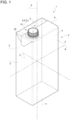
- Number 1 indicates as a whole a container, such as a bottle, a package, a can or the like, comprising a main body 2 and a closure assembly 3 coupled or coupleable to main body 2.
- container 1 is filled or fillable with a pourable product, in particular a pourable food product, even more particular a sterilized and/or a sterile-processed pourable food product, such as fruit juice, milk (e.g. ultra-high-temperature treated milk), wine, tomato sauce, sugar, salt and others.
- a pourable product in particular a pourable food product, even more particular a sterilized and/or a sterile-processed pourable food product, such as fruit juice, milk (e.g. ultra-high-temperature treated milk), wine, tomato sauce, sugar, salt and others.
- containers 1 in particular main bodies 2, obtained from a web of packaging material having a multilayer structure, although this is in no way intended to limit the scope of protection as defined by the accompanying claims.
- the web of packaging material comprises at least a layer of fibrous material, such as e.g. a paper or cardboard layer, and at least two layers of heat-seal plastic material, e.g. polyethylene, interposing the layer of fibrous material in between one another.
- a layer of fibrous material such as e.g. a paper or cardboard layer
- heat-seal plastic material e.g. polyethylene
- the web of packaging material also comprises a layer of gas- and light-barrier material, e.g. aluminum foil or ethylene vinyl alcohol (EVOH) film, in particular being arranged between one of the layers of the heat-seal plastic material and the layer of fibrous material.
- a layer of gas- and light-barrier material e.g. aluminum foil or ethylene vinyl alcohol (EVOH) film
- EVOH ethylene vinyl alcohol
- the web of packaging material also comprises a further layer of heat-seal plastic material being interposed between the layer of gas- and light-barrier material and the layer of fibrous material.
- main body 2 defines a sealed package, in particular a sealed carton package, having a designated pour opening surface area (not shown and known as such), and closure assembly 3 is fitted to main body 2 about the designated pour opening surface area.
- closure assembly(ies) 3 is(are) applied to main body(ies) 2 prior, during or after formation, filling and sealing of main body(ies) 2 by means of a molding process and/or adhesive bonding and/or ultrasonic bonding.
- closure assembly(ies) 3 can be applied onto the web of packaging material prior to arranging the web of packaging material within or during advancement of the web of packaging material within a packaging machine for forming, filling and sealing main body(ies) 2 from the web of packaging material.
- main body 2 extends along a longitudinal axis A, a first transversal axis B and a second transversal axis C.
- longitudinal axis A is perpendicular to first transversal axis B and second transversal axis C and first transversal axis B and second transversal axis C are perpendicular to one another.
- the extension of main body 2 along longitudinal axis A is larger than the extension of main body 2 along first transversal axis B and second transversal axis C.
- main body 2 is parallelepiped-shaped.
- main body 2 comprises a first wall portion 4, in particular being transversal, even more particular perpendicular, to longitudinal axis A, from which main body 2 extends along longitudinal axis A.
- first wall portion 4 defines a support surface of container 1, in particular main body 2, which, in use, can be put in contact with a support, such as e.g. a shelf, when, in use, being e.g. exposed within a sales point or when being stored.
- a support such as e.g. a shelf
- first wall portion 4 defines a bottom wall portion.
- main body 2 also comprises a plurality of lateral walls 5 being (fixedly) connected to first wall portion 4 and extending, in particular substantially parallel to longitudinal axis A, from first wall portion 4.
- main body 2 also comprises a second wall portion 6 opposite to first wall portion 4 and being (fixedly) connected to lateral walls 5.
- lateral walls 5 are interposed between first wall portion 4 and second wall portion 6.
- second wall portion 6 defines a top wall portion.
- first wall portion 4 and second wall portion 6 may be parallel to one another.
- first wall portion 4 and second wall portion 6 could be inclined with respect to one another.
- second wall portion 6 comprises the designated pour opening surface area.
- the designated pour opening surface area of main body 2 comprises a pouring hole allowing for the outflow of the pourable product from main body 2.
- the designated pour opening surface area also comprises a separation membrane sealing the pouring hole.
- the separation membrane is configured to retain the pourable product within main body 2 when being intact and to be at least partially (and non-reversibly) openable and/or rupturable and/or cuttable and/or piercable so as to allow the outflow of the pourable product from main body 2 through at least a portion of the pouring hole.
- the separation membrane is configured to allow the outflow of the pourable product after its loss of integrity and to protect the pourable product from the outer environment prior to its cutting and/or opening and/or rupturing and/or piercing.
- the separation membrane comprises a gas- and light-barrier material, e.g. aluminum foil or ethylene vinyl alcohol (EVOH) film.
- a gas- and light-barrier material e.g. aluminum foil or ethylene vinyl alcohol (EVOH) film.
- the separation membrane is defined by a portion of the web of packaging material, in particular a portion of the layers of the web of packaging material being different from the layer of fibrous material.
- closure assembly 3 comprises and/or is formed from a polymeric material.
- closure assembly 3 could comprise and/or is formed from a metallic material.
- closure assembly 3 comprises at least:
- closure assembly 3 also comprises:
- coupling element 13 is connected to lid 10 and first ring member 11 or second ring member 12 in a non-rupturable manner and/or separation resistant manner. This means that upon a normal use of closure assembly 3 coupling element 13 remains connected to lid 10 and first ring member 11 or second ring member 12.
- the respective connections between lid 10 and first ring member 11 or second ring member 12 are designed to resist an acting force, which exceeds the forces that typically act during a normal use of closure assembly 3.
- coupling element 13 is string-shaped.
- coupling element 13 could have any other shape (e.g. being an endless coupling element) and/or closure assembly 3 comprises more than one coupling element 13 and/or coupling clement 13 comprises different portions being connected to lid 10 and/or first ring member 11 and/or second ring member 12.
- each first coupling bridge 14 is arranged in a respective non-ruptured configuration when being connected to first ring member 11 and second ring member 12 and a respective ruptured configuration when being ruptured (i.e. the respective first coupling bridge 14 is disconnected from first ring member 11 and/or second ring member 12.
- each second coupling bridge 15 is arranged in a respective non-ruptured configuration when being connected to second ring member 12 and lid 10 and a respective ruptured configuration when being ruptured (i.e. the respective second coupling bridge 15 is disconnected from second ring member 12 and/or lid 10).
- each first coupling bridge 14 and each second coupling bridge 15 is the respective initial configuration (i.e. a user handling container 1 for the first time, finds first coupling bridges and second coupling bridges 15 in their non-ruptured configuration) and the control from the respective non-ruptured configuration to the respective ruptured configuration is irreversible.
- first coupling bridges 14 and second coupling bridges 15 are designed to define at least an initial state of closure assembly 3 in which first coupling bridges 14 and second coupling bridges 15 are arranged in the respective non-ruptured configuration (i.e. first coupling bridges 14 and second coupling bridges 15 are connected to respectively first ring member 11 and second ring member 12 and to lid 10 and second ring member 12).
- closure assembly 3 when being in the initial state is intact (i.e. no manipulation or use of closure assembly 3 has been initiated or tried).
- the state of closure assembly 3 corresponds to the one in which closure assembly 3 was applied to main body 2.
- closure assembly 3 is arranged in a manipulated state with first coupling bridges 14 and second coupling bridges 15 being arranged in the respective ruptured configurations (i.e. lid 10 is disconnected from second ring member 12 by means of second coupling bridges 15 (while still being connected by means of coupling element 13) and first ring member 11 and second ring member 12 are disconnected from one another).
- each first coupling bridge 14 is designed to rupture at a force being equal or larger than a first rupturing force and each second coupling bridge 15 is designed to rupture at a force being equal or larger than a second rupturing force.
- the first rupturing force is smaller than the second rupturing force.
- At least first ring member 14 acts as a tamper-evidence or in other words, first ring member 14 is designed as a tamper-evidence element.
- second ring member 15 acts as a tamper-evidence.
- closure assembly 3 is in an intermediate state with first coupling bridges 14 being arranged in the ruptured configuration ad second coupling bridges 15 being arranged in the non-ruptured configuration.
- closure assembly 3 is at first controlled from the initial state to the intermediate state and then from the intermediate state to the manipulated state.
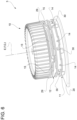
- closure assembly 3 also comprises a collar 16 delimiting and/or defining a pouring outlet 17 (of container 1), the pouring outlet 17 being configured to allow for the outflow of the pourable product from container 1.
- first ring member 11 and second ring member 12 are coupled to and surround collar 16; and lid 10 is connected and/or connectable to collar 16 and is configured to selectively close and open pouring outlet 17 for respectively impeding and allowing the outflow of the pourable product from container 1 through pouring outlet 17.
- first ring member 11 and second ring member 12 are coaxial to collar 16.
- first ring member 11 and/or second ring member 12 is/are coupled to collar 16 in a rotatable manner around respectively a rotation axis E and a rotation axis F, and in particular around collar 16.
- rotation axis E and rotation axis F being transversal to first transversal axis B and second transversal axis C.
- lid 10 and collar 16 are designed such that lid 10 can be fastened to and loosened from collar 16 by means of rotation (by means of respectively screwing and unscrewing) of lid 10 with respect to collar 16 around a rotation axis G.
- rotation axis G being transversal to first transversal axis B and second transversal axis C.
- lid 10 comprises an inner threaded portion 18, in particular arranged at an inner surface of lid 10
- collar 16 comprises an outer threaded portion 19, in particular arranged at an outer surface of collar 16.
- Inner threaded portion 18 and outer threaded portion 19 are configured to allow for selectively fastening and loosening lid 10 to and from collar 16 by means of a relative rotation between lid 10 and collar 16.
- closure assembly 3 further comprises a coupling base 20 carrying collar 16 and being configured to couple and/or connect (see Figures 4 to 6 ) and/or being coupled and/or connected to (see Figures 1 to 3 ) main body 2.
- coupling base 20 is configured to be fixed and/or is fixed to an outer surface of main body 2, in particular of second wall portion 6.
- coupling base 20 is arranged in the area of, even more particular at, the designated pour opening surface area.
- coupling base 20 comprises an opening, in particular a circular opening
- collar 16 surrounds the opening so that, in use, with the separation membrane being opened and/or cut and/or ruptured and/or pierced a fluid connection between the inside of main body 2 and pouring outlet 17 is established (i.e. the pourable product can flow out of container 1).
- At least a portion of coupling base 20 (substantially) has a plate-like configuration.
- collar 16 extends, in particular from coupling base 20, along, in particular parallel to, a longitudinal axis I, in particular longitudinal axis I being a central axis of collar 16.
- the opening of coupling base 20, collar 16 and the pouring hole are coaxial to one another.
- rotation axis G and longitudinal axis I are parallel, in particular coaxial, to one another.
- collar 16 has a circular shape, in particular a circular cross-sectional shape with respect to a sectional plane being orthogonal to longitudinal axis I.
- closure assembly 3 also comprises a cutting device 24 configured to rupture and/or pierce and/or cut and/or open the separation membrane and a control device configured to control cutting device 24 from a rest position to an operative position in which cutting device 24 is adapted to rupture and/or pierce and/or cut and/or open the separation membrane.
- cutting device 24 has an annular shape and is arranged within an inner space 25 of collar 16 when being arranged in the rest position and protrudes at least partially out of inner space 25 when being controlled in the operative position.
- cutting device 24 is arranged in the rest position with closure assembly 3 being arranged in the initial state and is arranged in the operative position with closure assembly 3 being arranged in the manipulated state.
- cutting device 24 is, in use, controlled by means of the control device from the rest configuration to the operative configuration during control of closure assembly 3 from the intermediate state to the manipulated state.
- cutting device 24 is in an axially raised position (with respect to longitudinal axis I) when being arranged in the rest position and with respect to the operative position.
- control device comprises control flaps 26, in particular connected to lid 10, interaction elements 27 connected to cutting device 24 and a cam mechanism 28 (see Figure 4 ; known as such and not described in detail) partially associated to cutting device 24 and partially associated to collar 16.
- control flaps 26 are configured to and/or protrude into inner space 25.
- control flaps 26 are connected to and protrude away from an inner surface portion of lid 10.
- control device is actuatable through rotation of control flaps 26 around a respective rotation axis, in particular by means of rotation of lid 10 around rotation axis G.
- rotation of control flaps 26 leads, in use, to a rototraslatory movement of cutting device 24, which is guided by means of cam mechanism 28.
- lid 10 is controllable in at least a first operative configuration (see Figures 1 , 2 , 5 and 6 ) in which lid 10 is coaxial to first ring member 11 and/or second ring member 12 and a second operative configuration (see Figures 3 and 7 ) in which lid 10 is transversally arranged with respect to first ring member 11 and/or second ring member 12.
- lid 10 is configured to close and open pouring outlet 17 with lid 10 being controlled in respectively the first operative configuration and the second operative configuration.
- lid 10 is controlled in the first operative configuration and the second operative configuration with lid 10 itself being respectively connected to and detached from collar 16.
- lid 10 is coaxial to collar 16 when being controlled in the first operative configuration and preferentially but not necessarily is transversal to collar 16 when being controlled in the second operative configuration.
- lid 10 when lid 10 is arranged in the first operative configuration lid 10 is connected to collar 16 and covers pouring outlet 17 and when lid 10 is arranged in the second operative configuration lid 10 is detached from collar 16 and clears pouring outlet 17.
- a ring portion 29 of lid 10 is parallel to and transversal to ring member 11 when being controlled in respectively the first operative configuration and the second operative configuration. This latter reflects the fact that lid 10 needs to be distanced and/or separated from first ring member 11 and/or second ring member 12 for allowing the outflow of the pourable product through pouring outlet 17 (see e.g. Figures 3 and 7 ).
- coupling element 13 is connected to ring portion 29.
- second ring member 12 is interposed between lid 10 and first ring member 11 with lid 10 being controlled in the first operative configuration.
- lid 10 is arranged in the first operative configuration with closure assembly 3 being controlled in the initial state.
- closure assembly 3 in particular lid 10, first ring member 11, second ring member 12, first coupling bridges 14 and second coupling bridges 15 are designed such that the first time lid 10 is controlled from the first operative configuration, closure assembly 3 is controlled from the initial state to the manipulated state, in particular from the initial state to the intermediate state and from the intermediate state to the manipulated state.
- lid 10 can be controlled between the first operative configuration and the second operative configuration a plurality of times.
- control device is configured to move cutting device 24 from the rest position to the operative position when, in use, closure assembly 3 is in the initial state and during control of lid 10 from the first operative configuration to the second operative configuration.
- control flaps 26 protrude into and are removed from inner space 25 with lid 10 being arranged in respectively the first operative configuration and the second operative configuration.
- lid 10 is configured to be controlled between the first operative configuration and the second operative configuration by means of a relative rotation of lid 10 around rotation axis G.
- inner threaded portion 18 and outer threaded portion 19 are configured to guide the control of lid 10 between the first operative configuration and the second operative configuration.
- lid 10 is controlled, in use, from the first operative configuration to the second operative configuration and from the second operative configuration to the first operative configuration by rotation of lid 10 around rotation axis G in, respectively, a first sense of rotation and a second sense of rotation opposite to the first sense of rotation.
- first ring member 11 and second ring member 12 are axially displaced (with respect to rotation axis G and/or longitudinal axis I) from one another.
- first ring member 11 is interposed between second ring member 12 and coupling base 20.
- closure assembly 3 further comprises:
- first rupturing device and the second rupturing device are activated during control of lid 10 from the first operative configuration to the second operative configuration, in particular by means of rotation of lid 10 around rotation axis G.
- the first rupturing device and the second rupturing device are configured such that first coupling bridges 14 rupture prior to second coupling bridges 15 during control of closure assembly 3 from the initial state to the manipulated state.
- the first rupturing device is activated, in use, during control of closure assembly 3 from the initial state to the intermediate state and the second rupturing device is activated, in use, during control of closure assembly 3 from the intermediate state to the manipulated state.
- the first rupturing device is configured to create a force which equals or is larger than the first rupturing force and which is lower than the second rupturing force
- the second rupturing device is configured to create a force, which equals or is larger than the second rupturing force.
- the first rupturing device comprises one or more first interaction elements 30 associated to and/or carried by collar 16 and one or more second interaction elements 31 associated to and/or carried by first ring member 11.
- each second interaction element 31 is configured to abut against one respective first interaction element 30 for actuating the non-reversible rupturing of first coupling bridges 14.
- each second interaction element 31 and the respective first interaction element 30 are designed such that the second interaction element 31 abuts, in use, against the respective first interaction element 30 upon a relative rotation of first ring member 11 (around rotation axis E and) with respect to collar 16.
- each second interaction element 31 and the respective first interaction element 30 are arranged such that each second interaction element 31 abuts, in use, against the respective first interaction element 30 within a relative angular movement of first ring member 11 with respect to first interaction elements 30 of at most 20°.
- first interaction elements 30 are connected to an outer surface of collar 26 and radially protrude away from collar 26.
- first interaction elements 30 are equally spaced around longitudinal axis I.
- second interaction elements 31 are connected to an inner surface of first ring member 11 facing the outer surface of collar 16 and radially protrude away from first ring member 11.
- second interaction elements 31 are equally spaced around rotation axis E.
- the second rupturing device comprises at least one first interaction member 32 associated to and/or carried by collar 16 and one or more second interaction members 33 associated to and/or carried by second ring member 12.
- each second interaction member 33 is configured to abut against at least one respective portion of first interaction member 32 for actuating the non-reversible rupturing of second coupling bridges 15.
- each second interaction member 33 and the respective first interaction member 32 are designed such that each second interaction element 33 abuts, in use, against at least a respective portion of first interaction member 32 upon a relative axial movement of second ring member 12 with respect to first interaction member 32 and/or collar 16.
- the relative axial movement is actuated by means of rotation of lid 10 around rotation axis G and the interaction between inner threaded portion 18 and outer threaded portion 19.
- second interaction members 33, first interaction member 32 and inner threaded portion 18 and outer threaded portion 19 are arranged such that second interaction members 33 abut, in use, against the respective portions of first interaction member 32 within a relative angular movement of lid 10 around rotation axis G of at least 20° and of at most 45°.
- first interaction member 32 is connected to the outer surface of collar 26 and radially protrudes away from collar 26.
- first interaction member 32 comprises a ring element connected to and surrounding collar 16 in a non-rotatable manner. Even more particular, the ring element is integral to collar 16.
- first interaction member 32 is axially displaced (with respect to longitudinal axis I and) with respect to first interaction elements 30.
- first interaction elements 30 are interposed between first interaction member 32 and coupling base 20.
- second interaction members 33 are connected to an inner surface of second ring member 12 facing the outer surface of collar 16 and radially protrude away from second ring member 12.
- second interaction members 33 are equally spaced around rotation axis F.
- second interaction members 33 are in the form of flaps protruding from the inner surface of second ring member 12.
- second ring member 12 comprises a recess 36 for hosting at least a portion of coupling element 13 and second ring member 12 and lid 10 are axially spaced from another such to host another portion of coupling element 13 with closure assembly 3 being in the first operative configuration.
- a user In use, a user needs to execute a first step of controlling, during which closure assembly 3 is controlled from the initial state to the manipulated state (prior to a step of outpouring of the pourable product from container 1) .
- closure assembly 3 is controlled such that first coupling bridges 14 and second coupling bridges 15 rupture, while lid 10 and second ring member 12 remain connected to one another by means of coupling element 13.
- first closure assembly 3 is controlled from the initial state to the intermediate state followed by the control of closure assembly 3 from the intermediate state to the manipulated state.
- first coupling bridges 14 rupture disconnecting first ring member 11 and second ring member 12 from one another and during the control from the intermediate state to the manipulated state second coupling bridges 15 rupture so that second ring member 12 and lid 10 remain connected to one another only by means of coupling element 13.
- the first rupturing device is activated followed by the activation of the second rupturing device.
- a second step of controlling is executed, during which lid 10 is controlled from the first operative configuration to the second operative configuration.
- lid 10 is (reversibly) controlled form the first operative configuration to the second operative configuration by means of rotation of lid 10 around rotation axis G and/or collar 16.
- control of lid 10 from the first operative configuration to the second operative configuration actuates (at first) the first rupturing device and (then) the second rupturing device for rupturing respectively the first coupling bridges 14 and the second coupling bridges 15.
- both first ring member 11 and second ring member 12 rotate around respectively rotation axis E and rotation axis F due the connection of lid 10 and second ring member 12 by means of coupling element 13 and second coupling bridges 15 and the connection of second ring member 12 and first ring member 11 by means of first coupling bridges 14.
- first ring member 11 results in a relative angular movement between each second interaction element 31 and the respective first interaction element 30 until each second interaction element 31 abuts against the respective first interaction element 30, leading to the establishment of the first rupturing force and the rupturing of first coupling bridges 14. This also means that any further rotation of lid 10 is not transferred to first ring member 11.
- second ring member 12 is (together with lid 10) also axially displaced, in particular due to the interaction between inner threaded portion 18 and outer threaded portion 19, resulting in a relative axial movement between second interaction members 33 and first interaction member 32 until each second interaction member 33 abuts against the respective portion of first interaction member 32, leading to the establishment of the second rupturing force and the rupturing of second coupling bridges 15.
- This also means that any further rotation of lid 10 is transferred to second ring member 12 by means of coupling element 13 only.
- second ring member 12 rotates around rotation axis F.
- cutting device 24 is activated for rupturing and/or cutting and/or piercing and/or opening the separation membrane.
- closure assembly 3 according to the present invention will be clear from the foregoing description.
- lid 10 is coupled to container 1 independently on whether lid 10 is controlled in the first operative configuration or the second operative configuration or any configuration intermediate to both.
- first ring member 11 clearly allows for a tamper evidence as additionally also the second coupling bridges 15 indicate a tampering.
- closure assemblies 3 can be realized relying on molds similar to the one known requiring only minor modifications.
- a further advantage resides in that coupling element 13 allows to control the relative position and the distance between lid 10 and second ring member 12 in a flexible manner.
Applications Claiming Priority (2)
| Application Number | Priority Date | Filing Date | Title |
|---|---|---|---|
| EP19200328 | 2019-09-30 | ||
| EP20196227.1A EP3805126B1 (de) | 2019-09-30 | 2020-09-15 | Verschlussanordnung für behälter und behälter mit verschlussanordnung |
Related Parent Applications (2)
| Application Number | Title | Priority Date | Filing Date |
|---|---|---|---|
| EP20196227.1A Division EP3805126B1 (de) | 2019-09-30 | 2020-09-15 | Verschlussanordnung für behälter und behälter mit verschlussanordnung |
| EP20196227.1A Division-Into EP3805126B1 (de) | 2019-09-30 | 2020-09-15 | Verschlussanordnung für behälter und behälter mit verschlussanordnung |
Publications (3)
| Publication Number | Publication Date |
|---|---|
| EP4173987A1 true EP4173987A1 (de) | 2023-05-03 |
| EP4173987C0 EP4173987C0 (de) | 2024-01-24 |
| EP4173987B1 EP4173987B1 (de) | 2024-01-24 |
Family
ID=68084725
Family Applications (3)
| Application Number | Title | Priority Date | Filing Date |
|---|---|---|---|
| EP23170960.1A Pending EP4234430A3 (de) | 2019-09-30 | 2020-09-15 | Verschlussanordnung für behälter und behälter mit verschlussanordnung |
| EP20196227.1A Active EP3805126B1 (de) | 2019-09-30 | 2020-09-15 | Verschlussanordnung für behälter und behälter mit verschlussanordnung |
| EP22207149.0A Active EP4173987B1 (de) | 2019-09-30 | 2020-09-15 | Verschlussanordnung für einen behälter und behälter mit einer verschlussanordnung |
Family Applications Before (2)
| Application Number | Title | Priority Date | Filing Date |
|---|---|---|---|
| EP23170960.1A Pending EP4234430A3 (de) | 2019-09-30 | 2020-09-15 | Verschlussanordnung für behälter und behälter mit verschlussanordnung |
| EP20196227.1A Active EP3805126B1 (de) | 2019-09-30 | 2020-09-15 | Verschlussanordnung für behälter und behälter mit verschlussanordnung |
Country Status (8)
| Country | Link |
|---|---|
| US (1) | US20220363447A1 (de) |
| EP (3) | EP4234430A3 (de) |
| JP (1) | JP2022550770A (de) |
| CN (2) | CN112572983A (de) |
| BR (1) | BR112022005864A2 (de) |
| ES (1) | ES2951519T3 (de) |
| MX (1) | MX2022002594A (de) |
| WO (1) | WO2021063669A1 (de) |
Families Citing this family (8)
| Publication number | Priority date | Publication date | Assignee | Title |
|---|---|---|---|---|
| EP4178868A1 (de) | 2020-07-10 | 2023-05-17 | Rosti Group AB | Mehrkomponentenverschluss |
| EP4166472B1 (de) | 2020-10-05 | 2024-04-03 | Tetra Laval Holdings & Finance S.A. | Behälter mit einer verschlussanordnung |
| DE102021112532A1 (de) | 2021-05-12 | 2022-11-17 | Bericap Holding Gmbh | Stegfreie, angebundene Verschlussvorrichtung |
| DE202021103289U1 (de) | 2021-06-03 | 2021-07-09 | Sig Technology Ag | Verschluss für einen Behälter mit besser kontrollierter Erstöffnung und verschiedene Anwendungsfälle dafür |
| EP4098574A1 (de) | 2021-06-03 | 2022-12-07 | SIG Combibloc Services AG | Verschluss für einen behälter mit kontrollierter erstöffnung |
| DE102021116173B3 (de) | 2021-06-22 | 2022-03-17 | Bericap Holding Gmbh | Bajonettverschluss |
| DE102021131389B3 (de) | 2021-11-30 | 2022-10-13 | Bericap Holding Gmbh | Verschlussvorrichtung mit Schneideinrichtung |
| DE102022110068B3 (de) | 2022-04-26 | 2023-03-02 | Bericap Holding Gmbh | Aseptische Verschlussvorrichtung |
Citations (7)
| Publication number | Priority date | Publication date | Assignee | Title |
|---|---|---|---|---|
| WO2002044050A1 (en) | 2000-11-28 | 2002-06-06 | Nisa, Trgovina In Storitve D.D. | Cap for bottle-like containers |
| JP2004307006A (ja) * | 2003-04-07 | 2004-11-04 | Toppan Printing Co Ltd | 封緘リング付キャップ |
| WO2007058440A1 (en) * | 2005-11-17 | 2007-05-24 | Sang Soo Yi | Ring cap |
| WO2009048273A2 (en) | 2007-10-10 | 2009-04-16 | Best Easy Cap Co., Ltd. | Container with anti-loss and anti-idle-rotation cap |
| EP2055640A1 (de) | 2007-11-05 | 2009-05-06 | Tetra Laval Holdings & Finance SA | Wiederverschließbare Öffnungsvorrichtung für Verpackungen von ausgießbaren Nahrungsmittelprodukten |
| US20120285921A1 (en) | 2010-01-25 | 2012-11-15 | Si-Joong Kwon | Container for preventing loss of stopper and idle rotation thereof |
| EP3715271A1 (de) | 2019-03-26 | 2020-09-30 | Tetra Laval Holdings & Finance S.A. | Öffnungsvorrichtung für eine verpackung, die ein rieselfähiges produkt enthält |
Family Cites Families (8)
| Publication number | Priority date | Publication date | Assignee | Title |
|---|---|---|---|---|
| EP0947433A1 (de) | 1998-04-03 | 1999-10-06 | Tetra Laval Holdings & Finance SA | Öffnungseinrichtung für Behälter mit fleissfähigem Lebensmittel |
| DE60121920T2 (de) * | 2001-05-29 | 2007-01-18 | Tetra Laval Holdings & Finance S.A. | Verschliessbare Öffnungs- und Ausgiessvorrichtung für versiegelte Lebensmittelbehälter |
| SI1730048T1 (sl) | 2004-04-02 | 2008-06-30 | Bormioli Rocco & Figlio Spa | Zapirka z dozirnim in odpirljivim varnostnim pokrovom, zlasti za steklenice z enkratnim doziranjem |
| JP4908225B2 (ja) * | 2004-09-30 | 2012-04-04 | テトラ ラバル ホールディングス アンド ファイナンス エス エイ | キャップ付き容器 |
| DE102010028518A1 (de) | 2010-05-04 | 2011-11-10 | Robert Bosch Gmbh | Verschlussvorrichtung |
| DE102016110047B3 (de) * | 2016-05-31 | 2017-05-04 | Sig Technology Ag | Ausgießelement für eine Verbundpackung sowie Verbundpackung mit einem Ausgießelement |
| IT201800010569A1 (it) | 2018-11-26 | 2020-05-26 | Easy Plast S R L | Dispositivo di apertura/chiusura per un contenitore per prodotti versabili |
| EP3689771A1 (de) | 2019-02-04 | 2020-08-05 | Tetra Laval Holdings & Finance S.A. | Tülle für eine verpackung und verpackung-tülle-anordnung |
-
2020
- 2020-09-15 JP JP2022519672A patent/JP2022550770A/ja active Pending
- 2020-09-15 EP EP23170960.1A patent/EP4234430A3/de active Pending
- 2020-09-15 MX MX2022002594A patent/MX2022002594A/es unknown
- 2020-09-15 WO PCT/EP2020/075747 patent/WO2021063669A1/en active Application Filing
- 2020-09-15 US US17/640,372 patent/US20220363447A1/en active Pending
- 2020-09-15 BR BR112022005864A patent/BR112022005864A2/pt unknown
- 2020-09-15 ES ES20196227T patent/ES2951519T3/es active Active
- 2020-09-15 EP EP20196227.1A patent/EP3805126B1/de active Active
- 2020-09-15 EP EP22207149.0A patent/EP4173987B1/de active Active
- 2020-09-25 CN CN202011025427.9A patent/CN112572983A/zh active Pending
- 2020-09-25 CN CN202022136937.5U patent/CN214421197U/zh active Active
Patent Citations (7)
| Publication number | Priority date | Publication date | Assignee | Title |
|---|---|---|---|---|
| WO2002044050A1 (en) | 2000-11-28 | 2002-06-06 | Nisa, Trgovina In Storitve D.D. | Cap for bottle-like containers |
| JP2004307006A (ja) * | 2003-04-07 | 2004-11-04 | Toppan Printing Co Ltd | 封緘リング付キャップ |
| WO2007058440A1 (en) * | 2005-11-17 | 2007-05-24 | Sang Soo Yi | Ring cap |
| WO2009048273A2 (en) | 2007-10-10 | 2009-04-16 | Best Easy Cap Co., Ltd. | Container with anti-loss and anti-idle-rotation cap |
| EP2055640A1 (de) | 2007-11-05 | 2009-05-06 | Tetra Laval Holdings & Finance SA | Wiederverschließbare Öffnungsvorrichtung für Verpackungen von ausgießbaren Nahrungsmittelprodukten |
| US20120285921A1 (en) | 2010-01-25 | 2012-11-15 | Si-Joong Kwon | Container for preventing loss of stopper and idle rotation thereof |
| EP3715271A1 (de) | 2019-03-26 | 2020-09-30 | Tetra Laval Holdings & Finance S.A. | Öffnungsvorrichtung für eine verpackung, die ein rieselfähiges produkt enthält |
Also Published As
| Publication number | Publication date |
|---|---|
| EP3805126A1 (de) | 2021-04-14 |
| JP2022550770A (ja) | 2022-12-05 |
| CN112572983A (zh) | 2021-03-30 |
| EP4234430A2 (de) | 2023-08-30 |
| US20220363447A1 (en) | 2022-11-17 |
| EP4173987C0 (de) | 2024-01-24 |
| BR112022005864A2 (pt) | 2022-06-21 |
| EP3805126B1 (de) | 2023-05-17 |
| MX2022002594A (es) | 2022-03-25 |
| EP4173987B1 (de) | 2024-01-24 |
| WO2021063669A1 (en) | 2021-04-08 |
| EP4234430A3 (de) | 2023-10-18 |
| CN214421197U (zh) | 2021-10-19 |
| ES2951519T3 (es) | 2023-10-23 |
Similar Documents
| Publication | Publication Date | Title |
|---|---|---|
| EP3805126B1 (de) | Verschlussanordnung für behälter und behälter mit verschlussanordnung | |
| EP3978387B1 (de) | Verschlussanordnung für behälter und behälter mit verschlussanordnung | |
| CN213009595U (zh) | 用于可倾倒产品的包装料的打开装置和含打开装置的包装 | |
| EP3798150A1 (de) | Verschlussanordnung für behälter und behälter mit verschlussanordnung | |
| US20230044435A1 (en) | Spout for a container and package-spout assembly | |
| US20230124456A1 (en) | Lid-spout assembly for a package and package having a lid-spout assembly | |
| RU2812027C1 (ru) | Укупорочный узел для контейнера и контейнер, имеющий укупорочный узел | |
| CN114981176A (zh) | 用于包装的壶嘴、用于包装的盖与壶嘴组件和具有壶嘴的包装 | |
| CN114981178A (zh) | 用于包装的壶嘴、用于包装的盖与壶嘴组件和具有壶嘴的包装 | |
| WO2024088804A1 (en) | Closure assembly for a container and container having a closure assembly | |
| EP4079652B1 (de) | Öffnungsvorrichtung für eine verpackung und verpackung mit einer öffnungsvorrichtung | |
| US20230115201A1 (en) | Lid assembly for a container, container having a lid assembly and method of coupling a lid assembly to a spout | |
| EP4159633B1 (de) | Öffnungsvorrichtung für eine verpackung und verpackung mit einer öffnungsvorrichtung | |
| WO2007128775A1 (en) | Pour spout fitment, attached to packaging material |
Legal Events
| Date | Code | Title | Description |
|---|---|---|---|
| PUAI | Public reference made under article 153(3) epc to a published international application that has entered the european phase |
Free format text: ORIGINAL CODE: 0009012 |
|
| STAA | Information on the status of an ep patent application or granted ep patent |
Free format text: STATUS: THE APPLICATION HAS BEEN PUBLISHED |
|
| STAA | Information on the status of an ep patent application or granted ep patent |
Free format text: STATUS: REQUEST FOR EXAMINATION WAS MADE |
|
| AC | Divisional application: reference to earlier application |
Ref document number: 3805126 Country of ref document: EP Kind code of ref document: P |
|
| AK | Designated contracting states |
Kind code of ref document: A1 Designated state(s): AL AT BE BG CH CY CZ DE DK EE ES FI FR GB GR HR HU IE IS IT LI LT LU LV MC MK MT NL NO PL PT RO RS SE SI SK SM TR |
|
| 17P | Request for examination filed |
Effective date: 20230403 |
|
| GRAP | Despatch of communication of intention to grant a patent |
Free format text: ORIGINAL CODE: EPIDOSNIGR1 |
|
| STAA | Information on the status of an ep patent application or granted ep patent |
Free format text: STATUS: GRANT OF PATENT IS INTENDED |
|
| TPAC | Observations filed by third parties |
Free format text: ORIGINAL CODE: EPIDOSNTIPA |
|
| RIC1 | Information provided on ipc code assigned before grant |
Ipc: B65D 55/16 20060101ALI20230602BHEP Ipc: B65D 41/34 20060101AFI20230602BHEP |
|
| INTG | Intention to grant announced |
Effective date: 20230623 |
|
| GRAJ | Information related to disapproval of communication of intention to grant by the applicant or resumption of examination proceedings by the epo deleted |
Free format text: ORIGINAL CODE: EPIDOSDIGR1 |
|
| STAA | Information on the status of an ep patent application or granted ep patent |
Free format text: STATUS: REQUEST FOR EXAMINATION WAS MADE |
|
| STAA | Information on the status of an ep patent application or granted ep patent |
Free format text: STATUS: EXAMINATION IS IN PROGRESS |
|
| INTC | Intention to grant announced (deleted) | ||
| 17Q | First examination report despatched |
Effective date: 20230821 |
|
| GRAP | Despatch of communication of intention to grant a patent |
Free format text: ORIGINAL CODE: EPIDOSNIGR1 |
|
| STAA | Information on the status of an ep patent application or granted ep patent |
Free format text: STATUS: GRANT OF PATENT IS INTENDED |
|
| TPAC | Observations filed by third parties |
Free format text: ORIGINAL CODE: EPIDOSNTIPA |
|
| TPAC | Observations filed by third parties |
Free format text: ORIGINAL CODE: EPIDOSNTIPA |
|
| GRAS | Grant fee paid |
Free format text: ORIGINAL CODE: EPIDOSNIGR3 |
|
| INTG | Intention to grant announced |
Effective date: 20231116 |
|
| RBV | Designated contracting states (corrected) |
Designated state(s): AL AT BE BG CH CY CZ DE DK EE ES FI FR GB GR HR HU IE IS IT LI LT LU LV MC MK MT NL NO PL PT RO RS SE SI SK SM TR |
|
| GRAA | (expected) grant |
Free format text: ORIGINAL CODE: 0009210 |
|
| STAA | Information on the status of an ep patent application or granted ep patent |
Free format text: STATUS: THE PATENT HAS BEEN GRANTED |
|
| AC | Divisional application: reference to earlier application |
Ref document number: 3805126 Country of ref document: EP Kind code of ref document: P |
|
| AK | Designated contracting states |
Kind code of ref document: B1 Designated state(s): AL AT BE BG CH CY CZ DE DK EE ES FI FR GB GR HR HU IE IS IT LI LT LU LV MC MK MT NL NO PL PT RO RS SE SI SK SM TR |
|
| REG | Reference to a national code |
Ref country code: GB Ref legal event code: FG4D |
|
| REG | Reference to a national code |
Ref country code: CH Ref legal event code: EP |
|
| REG | Reference to a national code |
Ref country code: IE Ref legal event code: FG4D |
|
| REG | Reference to a national code |
Ref country code: DE Ref legal event code: R096 Ref document number: 602020024928 Country of ref document: DE |
|
| U01 | Request for unitary effect filed |
Effective date: 20240215 |
|
| U07 | Unitary effect registered |
Designated state(s): AT BE BG DE DK EE FI FR IT LT LU LV MT NL PT SE SI Effective date: 20240226 |